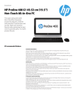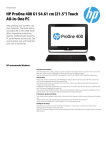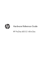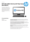
1
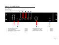
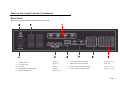
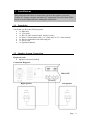
Sun-Tech OPERATION MANUAL PRO-ONE AV CONTROLLER Model: Operation Manual Version: 5.1 ST-PRO101 Page 1 ~ 24 Page 1 This device complies with Part 15 of the FCC Rules. Operation is subject to the following two conditions: (1) this device may not cause harmful interference, and (2) this device must accept any interference received, including interference that may cause undesired operation. Warning: Changes or modifications to this unit not expressly approved by the party responsible for compliance could void the user's authority to operate the equipment. NOTE: This equipment has been tested and found to comply with the limits for a Class B digital device, pursuant to Part 15 of the FCC Rules. These limits are designed to provide reasonable protection against harmful interference in a residential installation. This equipment generates, uses and can radiate radio frequency energy and, if not installed and used in accordance with the instructions, may cause harmful interference to radio communications. However, there is no guarantee that interference will not occur in a particular installation. If this equipment does cause harmful interference to radio or television reception, which can be determined by turning the equipment off and on, the user is encouraged to try to correct the interference by one or more of the following measures: Reorient or relocate the receiving antenna. Increase the separation between the equipment and receiver. Connect the equipment into an outlet on a circuit different from that to which the receiver is needed. Consult the dealer or an experienced radio/TV technician for help. Page 2 Welcome…… and thank you for purchasing this Sun-Tech PRO-ONE A/V Controller. This state of the art system includes everything you need to experience high quality digital video and audio in your multimedia learning environment. We have designed this system to be easy to set up, and even easier to operate. But please, review this manual before you operate your system; have it handy while you are setting the system up; and keep it available for future reference, or in the unlikely event that you encounter any unexpected problems. We have tried to keep this manual as simple as possible. It begins with a description of the important controls on the main unit and the software interface (only applicable to XCLASS Professional version). It then explains how to connect the speakers, computer, monitors, projector, IR output, and all external sources to the main unit. Finally, the detail instructions to operate the main unit and the software control interface in XCLASS Professional version. If you follow the instructions carefully, you can have the system up an operating in less than an hour. This system was designed to provide you with many years of reliable operation with minimum of care and maintenance. Every component in you system was in perfect working condition when it left out factory. If you experience any problem with the set up or operation of this system, please review the Trouble Shooting Guide at the end of this manual. Warnings, cautions and others CAUTION To reduce the risk of electrical shocks, fire, etc: 1. Do not remove screws, covers or cabinet. 2. Do not expose the appliance to rain or moisture. 3. Power off the unit before disconnecting the power cable. 4. Refer servicing to qualified service personnel only. BEFORE CONNECTING TO AC POWER, PLEASE MAKE SURE YOU HAVE SELECTED THE APPROPRIATE VOLTAGE SELECTION. FAILURE TO DO SO WILL PERMANENTLY DAMAGE YOUR UNIT. Notes. The appliance coupler is used as a disconnect device and shall be remain readily operable Page 3 Table of Contents Index to Parts and Controls Important Safeguards and Precautions Features of this System Important Information Regarding This Manual 1. Installations 1.1 1.2 1.3 1.4 1.5 1.6 Unpacking Speaker System Connection AV Equipments Input/Output Signal Connections Teacher PC and Laptop Connections Projector and Auxiliary Connections AC Power Connection 2. Basic System Setup and Operations 2.1 Voltage Selection 2.2 Basic Operations 2.3 Microphone Input and Control 3. Settings and Adjustments 3.1 Programming the Infrared Controller A. Additional Information A.1 Troubleshooting A.2 Technical Specifications 3 4~5 6 7 7 8 8 8~9 10 ~ 12 13 ~ 15 16 ~ 17 17 18 18 18 19 20 20 21 21 22 Page 4 Index to Parts and Controls Front Panel: Refer to the pages indicated in parentheses for details. 3 1 1. 2. 3. 4. 5. 4 5 6 7 2 Audio, Video Composite Inputs Power ON/OFF Indicator Infrared Receptor, Infrared Learning port Mic. Input Jack Mic. Volume Level Control 8 (page 12) (page 18) (page 20) (page 19) (page 19) 6. 7. 8. 9. Master Treble Level Control Master Bass Level Control Master Volume Level Control Power ON/OFF 9 (page 18) (page 18) (page 18) (page 18) Page 5 Index to Parts and Controls (Continued) Rear Panel: Refer to the pages indicated in parentheses for details. 2 3 1 1. 2. 3. 4. 5. Voltage Selector AC Power Plug Air Vents SPEAKER Output Terminals Infrared Output Jacks 6 4 (page 18) (page 17) (page 6) (page 8) (page 11, 17) 5 6. 7. 8. 9. 7 VGA Input/Output Terminals PRO-ONE Control Terminals Audio, Video Composite Outputs Audio, Video Composite Inputs 8 9 (page 14, 15, 17) (page 14) (page 11, 14, 17) (page 11, 14, 15) Page 6 Important Safeguards and Precautions Power Cord Protection To avoid any malfunction of the unit, and to protect against electric shock, fire or personal injury, please observer the following: Hold the plug firmly when connecting or disconnecting the AC power cord. Keep the AC power cord away from heating appliances. Never put any heavy object on the AC power cord. Do not attempt to repair or reconstruct the AC power cord in any way. Location and Handling Air vents are provided in the cabinet to prevent excessive heat inside the unit. Do not place this unit in closed space or anywhere blocking the vents. Do not place this unit in direct sunlight, or near heat sources. Keep this unit away from string magnetic objects. Do not insert or drop anything into this unit through the air vents as this could cause serious damage, possibly resulting in fire. Do not place any object containing water or other liquids on this unit. In the event that liquid should enter the cabinet, unplug this unit immediately and contact the retailer or service center immediately. Do not remove the cabinet. Touching parts inside the cabinet could result in electric shock and / or damage to the unit. Non-Use Periods When the unit is not being used, turn the unit off. When left unused for a long period of time, the unit should be unplugged from the household AC outlet. Stacking Place the unit in a horizontal position, and do not place anything heavy on top of it. Condensation Moisture may form inside the unit in the following conditions: In a steamy or very humid room. When the unit is suddenly moved from a cold environment to a warm one. If moisture forms inside this unit, it may not operate properly. In this case, turn on the power and wait about an hour for the moisture to evaporate. On Adjusting Volume Do not turn up the volume while listening to a portion with very low-level inputs or no audio signals. If you do, the speakers may be damaged when a peak level portion is played. Service Do not attempt to service the unit yourself. Page 7 Features of This System 7-channel A/V input 3-channel A/V output 1-channel microphone input 2-channel VGA input 1-channel VGA output with VGA connector x 2 (splitter) 50 W power amplifier with speaker outputs Programmable Infrared remote control (I/O) Mic volume, Master volume, treble and bass level control Power supply: 100-115/230V (user selectable) Rack Mountable Important Information Regarding This Manual The drawings about the front and rear panel used in this Operation Manual are purely for the purposes of explanation. The actual displays may slightly differ from what are shown here. Page 8 1. Installations This section describes how to connect the system to the speakers, projector, Teacher PC, Laptop computer and others AV equipments. Be sure to turn off the power of each component before making the connections. 1.1 Unpacking Check that you have the following items: 1 x Main unit 1 x VGA cable 1 x RS-232 cable (control cable, female to male) 2 x Stereo 3.5mm splitter cable (1 x 3.5mm male to 2 x 3.5mm female) 2 x Infrared transmitter with cable and jack 1 x Power cord 1 x Operation Manual 1.2 Speaker System Connection Required cords Speaker cord (not included) Connection Diagram: PRO-ONE Right Speaker Left Speaker Right Speaker Left Speaker Page 9 To avoid short-circuiting the speakers Make sure the stripped end of each speaker cord does not touch another speaker terminal or the stripped end of another speaker cord. Examples of poor connection of the speaker cord Stripped cords are touching each other due to excessive removal of insulation. Stripped speaker cord is touching another speaker terminal. Note: Be sure to match the speaker cord to the appropriate terminal on the components: + to + and - to -. If the cords are reversed, the sound will be distorted and will lack bass. Skill of connecting speaker wires: 1. Push down the Speaker terminal tab down to insert wire. 2. Push up the Speaker terminal tab to lock wire in the terminal. 3. Make sure the insulation is completely removed from the ends of the speaker wires at all connection points. Page 10 1.3 AV Equipments Input/Output Signal Connections Equipments mentioned in this section: DVD player Cassette Player VHS Player Digital Video Camera (DV Cam) Required cords Composite video cords (male to male) Composite audio cords (male to male) Infrared transmitter with cable and jack Note: The following table is the recommended. AV Input Channel AV Equipment Channel -3 DVD Player (Audio and Video) Channel- 4 VHS Player (Audio and Video) Channel- 5 Cassette Player (Audio only) Channel- 6 DV Camera (Audio and Video) Channel- 7 Visualizer (Audio and Video) *** CAUTION *** Since the order of these channels is hard coded into PRO-ONE and the control interface, YOU MUST CONNECT THE AV EQUIPMENTS TO THE CORRESPONDING CHANNELS. Fail to do so, may cause PRO-ONE malfunction. AV Output Channel Channel -1 Description Cassette Player (Audio) for recording. Page 11 Connection Diagram (1): Cassette Tape Player/Recorder Audio Left In Audio Right In PRO-ONE Point the Infrared transmitter towards those AV equipments. Infrared Transmitter Box Video Out Audio Left Out Audio Right Out Page 12 Connection Diagram (2): PRO-ONE Video Out Video Out Audio Left Out Audio Left Out Audio Right Out Audio Right Out DV Camera Visualizer Page 13 1.4 Teacher PC and Laptop Connections Equipments mentioned in this section: Teacher PC Laptop Computer (Optional) Required cords Composite video cords (male to male) Audio cable (1 x 3.5mm stereo male to 2 x composite male) Stereo 3.5mm splitter (1 x 3.5mm male to 2 x 3.5mm female) RS-232 Serial Cable (Straight-through) (female to male) VGA cable (male to male) Note: You would need additional cables, which are not mentioned above, to connect your laptop computer. Page 14 Teacher PC Connection Diagram: Label A B C D Description VGA signal output from the video card in the Teacher PC. Line Out from the sound card in the Teacher PC. (Optional) Composite video and audio signal input to the WinFast MPEG encoder card in the Teacher PC. Serial interface (COM1) of the Teacher PC. * *Note: Serial interface COM1 must be use in order to make PRO-ONE work properly. DO NOT USE COM2, THIS WILL NOT WORK! AV (Input) Channel Channel –1 (for Teacher PC use only) Channel –2 (for Laptop PC use only) AV (Output) Channel Channel -2 AV Equipment Teacher PC (Audio only) Laptop Computer (Audio only) AV Equipment (Optional) WinFast MPEG encoder card on Teacher PC. Page 15 Laptop Computer Connection Diagram: Laptop A B PRO-ONE Label A B Description VGA signal output from laptop computer* Line Out from the sound card in the laptop computer. *Note: Please make sure you have selected to output the video signal to the VGA output port at the back of the laptop computer. Audio Input Channel Channel -1 Channel -2 AV Equipment Teacher PC (Audio only) Laptop Computer (Audio only) Page 16 1.5 Projector and Auxiliary Connections Equipments mentioned in this section: Projector Required cords Composite video cords (male to male) Composite audio cords (male to male) Infrared transmitter with cable and jack VGA cable (male to male)* *Note: This VGA cable should come with your projector. AV Output Channel Channel -1 Channel -2 Channel -3 AV Equipment Projector –(video in) or Auxiliary Equipment* (Optional) WinFast MPEG encoder card on Teacher PC. Teacher sound card (Line-In port) *Note: The audio channels of output channel 1 are left unused, it can be connected to other equipment if necessary. Page 17 Projector Connection Diagram: Video In Composite Video In Point the Infrared transmitter towards the projector. PRO-ONE 1.6 AC Power Connection Notes Connecting to inappropriate power may damage the system or cause abnormal operation. (please refer to the voltage selection guide on page 18) Before connecting the AC power cord of this system to a wall outlet, connect the speakers and other component cables to the system. Page 18 2. Basic System Setup and Operations This section explains how to properly setup PRO-ONE to be used in different countries. Also, some basic function will be described. 2.1 Voltage Selection Before turning on the unit, please select the appropriate voltage setting for PRO-ONE. FAIL TO DO SO MAY CAUSE PERMEMNENT DAMAGE TO PRO-ONE. After powering up the unit, the red Power ON/OFF Indicator (refer to page 4) located on the front panel should be on. If not, please refer to our “Troubleshooting” section on page 21. 2.2 Basic Operations There are 3 knobs located on the front panel “Treble”, “Bass” and “VOL.”. They are all designed to provide a straightforward way to control the master output of PROONE. (please refer to the “Front Panel” view on page 4) Adjusting the master Volume, Treble and Bass levels: On the front panel: To increase the master volume level, turn the “VOL.” knob clockwise; to decrease it, turn the knob counterclockwise instead. To increase the master treble level, turn the “Treble” knob clockwise; to decrease it, turn the knob counterclockwise instead. To increase the master bass level, turn the “Bass” knob clockwise; to decrease it, turn the knob counterclockwise instead. Note: Additionally, a more sophisticated control over PRO-ONE reside in the XCLASS Control System software interface. For more detail, please refer to your XCLASS Operation Manual. Page 19 2.3 Microphone Input and Control A 6.3mm mono microphone jack named “Mic. In” is located on the front panel. Connect it with a microphone if you need. (please refer to the “Front Panel” view on page 4) Adjusting the microphone Volume: On the front panel: To increase the microphone volume level, turn the “Mic. Vol..” knob clockwise; to decrease it, turn the knob counterclockwise instead. Page 20 3. Settings and Adjustments This section explains how to use the “AV Infrared Learning Program” to program PRO-ONE in order to control other AV equipments. 3.1 Programming the Infrared Controller Before you start using your PRO-ONE AV control system, you have to “teach” PROONE how to control those AV devices. Since you may use it with various brands of AV equipments, we have integrated a programmable infrared controller into PROONE. PRO-ONE Infrared Learning System: Note: In the case below, we would demonstrate how to program PRO-ONE with the “PLAY” function of a DVD player which is connected to Channel -3. You would be able to program PRO-ONE with other functions and other devices by following the same procedures. 1. Before proceeding, please make sure you exit XCLASS Control System. 2. Open Windows Explorer and locate the file named “AV Learn.exe” located at “(XCLASS Teacher installation path)\AV Learn\AV Learn.exe” 3. Select the corresponding device channel number shown in the combo box; in this case you should select Channel – 3 for DVD 4. Point the DVD remote controller towards the “Infrared Learning Port” of PRO-ONE and keep the distance between them in about 10 to 15 cm. 5. Click the corresponding button on the learning software interface, for example “Play”. 6. Press the corresponding function button (“PLAY”) on the DVD remote controller within 1-2 seconds after step 5. 7. A “beep” sound will be heard after learning the code successfully. 8. Repeat the procedures above to program PRO-ONE for other functions and other AV equipments. 9. Close the “AV Learn” program and open XCLASS. 10. Click the buttons in the AV control panel to make sure the functions are learnt successfully. Remark: Please test all the function keys in XCLASS after the learning process. In case a key is not functioning as desired, please relearn that specific key button again. Page 21 A.1 Troubleshooting If you experience any of the following difficulties while using the system use this troubleshooting guide to help you remedy the problem. No power. (Power Indicator is off) Is the power cord firmly plugged into the power outlet? One of the safety mechanisms may be operating. In this case, unplug the player from the power outlet briefly and then plug it in again. If your problem persists, please contact our qualified service personnel. No picture. Check that the system is connected securely. The video connecting cord is damaged. Replace it with a new one. Make sure you connect the system to the video input connector of the projector. Make sure the projector is turned on. Make sure the infrared transmitter has a direct line-of-sight with the infrared receiver of the projector. There is no sound or only a very low-level sound is heard. Check that the speakers and components are connected securely Make sure that you have selected the correct source on the system. Make sure that you have not selected “Mute” from the XCLASS software interface. The protective device on the system has been activated because of a short circuit. Turn the system off, eliminate the short-circuit problem and turn on the power again. The audio connecting cord is damaged. Replace it with a new one. Severe hum or noise is heard. Check that the speakers and components are connected securely. Check that the connecting cords are away from a transformer or motor, and at least 3 meters away from a TV set or fluorescent light. The plugs and jacks are dirty. Wipe them with a cloth slightly moistened with alcohol. Severe high-pitch or “V” noise is heard. Check that the serial (RS-232) cable and PRO-ONE are connected securely. Check that the serial (RS-232) cable and “Teacher PC” are connected securely. Cannot control AV equipments. Check that the serial (RS-232) cable is connected to COM1 on Teacher PC. Check that the serial port on Teacher PC is enabled in the bios. Make sure you have programmed PRO-ONE to use the infrared code of that specific AV equipment. (please refer to the learning procedure on page 20) Page 22 General Infrared Control Power Amplifier Video Switch Audio Switch VGA Switch A.2 Specifications Slew rate: Bandwidth: Gain Matching: Input: Output: Cross-talk: Channels Isolation: Input: Output: Cross-talk: Channels Isolation: Voltage Gain: Bandwidth: Input: Output: Power: Total Harmonic Distortion (T.H.D.) Signal to Noise Ratio (SN ratio) Frequency Response: 1100V/μs 250MHz (@ -3dB) R to G to B: 0.10dB Input 1 to Input 2: 0.01dB 2-channel standard VGA signal Connectors: DB-15 (female) x 2 2-channel synchronized VGA signal Impedance: 75 ohms Connectors: DB-15 (female) x 2 -75 dB -80 dB 7-channel stereo inputs Connectors: Composite Stereo (female) x 7 3-channel synchronized outputs: (3 x channel without amplification) Connectors: Composite Stereo (female) x 3 -60 dB (@ VIN=1Vpp: f=3MHz) -75 dB 6 dB (@ 1MHz: VIN=1Vpp) 10MHz 7-channel composite inputs Connectors: Composite (female) x 7 3-channel composite outputs Connectors: Composite (female) x 3 50W + 50W (@ 8 ohms) <0.2% (@ 1kHz, 10W, 8 ohms) 75 dB 20 Hz – 20 kHz, ± 2dB Mic. Input Sensitivity: 20 mV Reception Frequency: 15 kHz – 50kHz (infrared) Reception Error: <5% Memory Size: 256 codes Transmission Range: >3 meters Power Requirements: Power Consumption: 100-115/ 230 V AC, 50/ 60 Hz 120 W With mounting bracket: 482 mm(W) x 87 mm(H) x 245 mm(D) Without mounting bracket: 440 mm(W) x 87 mm(H) x 245 mm(D) 6.5 lb 0 °C – 40 °C (32 °F – 104 °F) 5% - 90% -20 °C – 55 °C (-4 °F – 130 °F) See page 7 Dimensions Net Weight: Operating Temperature: Operating Humidity: Storage Temperature: Supplied accessories: Note: Designs and specifications are subjected to change without notice. Weight and dimensions are approximate. Illustrations may differ slightly from production models. Page 23 http://www.suntechgroup.com SUN-TECH International Group Limited Sun-Tech International Group Limited 22/F, 9 Chong Yip Street, Kwun Tong, Kowloon, Hong Kong Tel.852-27830868 Fax.852-27806644 Email: [email protected] Distributor: Page 24