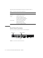
1
Sun Fire V210 and V240 Servers
Administration Guide
Sun Microsystems, Inc.
4150 Network Circle
Santa Clara, CA 95054 U.S.A.
650-960-1300
Part No. 816-4826-11
April 2003, Revision A
Send comments about this document to: [email protected]
Copyright 2002 Sun Microsystems, Inc., 4150 Network Circle, Santa Clara, CA 95054 U.S.A. All rights reserved.
This product or document is distributed under licenses restricting its use, copying, distribution, and decompilation. No part of this product or
document may be reproduced in any form by any means without prior written authorization of Sun and its licensors, if any. Third-party
software, including font technology, is copyrighted and licensed from Sun suppliers.
Parts of the product may be derived from Berkeley BSD systems, licensed from the University of California. UNIX is a registered trademark in
the U.S. and other countries, exclusively licensed through X/Open Company, Ltd.
Sun, Sun Microsystems, the Sun logo, AnswerBook2, docs.sun.com, and Solaris are trademarks, registered trademarks, or service marks of Sun
Microsystems, Inc. in the U.S. and other countries. All SPARC trademarks are used under license and are trademarks or registered trademarks
of SPARC International, Inc. in the U.S. and other countries. Products bearing SPARC trademarks are based upon an architecture developed by
Sun Microsystems, Inc. The Energy Star logo is a registered trademark of EPA.
The OPEN LOOK and Sun™ Graphical User Interface was developed by Sun Microsystems, Inc. for its users and licensees. Sun acknowledges
the pioneering efforts of Xerox in researching and developing the concept of visual or graphical user interfaces for the computer industry. Sun
holds a non-exclusive license from Xerox to the Xerox Graphical User Interface, which license also covers Sun’s licensees who implement OPEN
LOOK GUIs and otherwise comply with Sun’s written license agreements.
Federal Acquisitions: Commercial Software—Government Users Subject to Standard License Terms and Conditions.
DOCUMENTATION IS PROVIDED “AS IS” AND ALL EXPRESS OR IMPLIED CONDITIONS, REPRESENTATIONS AND WARRANTIES,
INCLUDING ANY IMPLIED WARRANTY OF MERCHANTABILITY, FITNESS FOR A PARTICULAR PURPOSE OR NON-INFRINGEMENT,
ARE DISCLAIMED, EXCEPT TO THE EXTENT THAT SUCH DISCLAIMERS ARE HELD TO BE LEGALLY INVALID.
Copyright 2002 Sun Microsystems, Inc., 4150 Network Circle, Santa Clara, CA 95054 Etats-Unis. Tous droits réservés.
Ce produit ou document est distribué avec des licences qui en restreignent l’utilisation, la copie, la distribution, et la décompilation. Aucune
partie de ce produit ou document ne peut être reproduite sous aucune forme, par quelque moyen que ce soit, sans l’autorisation préalable et
écrite de Sun et de ses bailleurs de licence, s’il y en a. Le logiciel détenu par des tiers, et qui comprend la technologie relative aux polices de
caractères, est protégé par un copyright et licencié par des fournisseurs de Sun.
Des parties de ce produit pourront être dérivées des systèmes Berkeley BSD licenciés par l’Université de Californie. UNIX est une marque
déposée aux Etats-Unis et dans d’autres pays et licenciée exclusivement par X/Open Company, Ltd.
Sun, Sun Microsystems, le logo Sun, AnswerBook2, docs.sun.com, et Solaris sont des marques de fabrique ou des marques déposées, ou
marques de service, de Sun Microsystems, Inc. aux Etats-Unis et dans d’autres pays. Toutes les marques SPARC sont utilisées sous licence et
sont des marques de fabrique ou des marques déposées de SPARC International, Inc. aux Etats-Unis et dans d’autres pays. Les produits portant
les marques SPARC sont basés sur une architecture développée par Sun Microsystems, Inc.
L’interface d’utilisation graphique OPEN LOOK et Sun™ a été développée par Sun Microsystems, Inc. pour ses utilisateurs et licenciés. Sun
reconnaît les efforts de pionniers de Xerox pour la recherche et le développement du concept des interfaces d’utilisation visuelle ou graphique
pour l’industrie de l’informatique. Sun détient une licence non exclusive de Xerox sur l’interface d’utilisation graphique Xerox, cette licence
couvrant également les licenciés de Sun qui mettent en place l’interface d’utilisation graphique OPEN LOOK et qui en outre se conforment aux
licences écrites de Sun.
Achats fédéraux : logiciel commercial - Les utilisateurs gouvernementaux doivent respecter les conditions du contrat de licence standard.
LA DOCUMENTATION EST FOURNIE “EN L’ETAT” ET TOUTES AUTRES CONDITIONS, DECLARATIONS ET GARANTIES EXPRESSES
OU TACITES SONT FORMELLEMENT EXCLUES, DANS LA MESURE AUTORISEE PAR LA LOI APPLICABLE, Y COMPRIS NOTAMMENT
TOUTE GARANTIE IMPLICITE RELATIVE A LA QUALITE MARCHANDE, A L’APTITUDE A UNE UTILISATION PARTICULIERE OU A
L’ABSENCE DE CONTREFAÇON.
Please
Recycle
Contents
1.
Introduction
1
Overview of the Servers
2
Sun Fire V210 Server
2
Sun Fire V240 Server
3
Features
3
Differences Between The Servers
Bezel Features
4
4
Server Status Indicators
5
▼
To Turn The Locator LED On
6
▼
To Turn The Locator LED Off
6
Front Panel Features
7
On/Standby Switch
7
Hard disk drives
9
DVD-ROM Drive
9
System Configuration Card (SCC)
10
Keyswitch (Sun Fire V240 server only)
Back Panel Features
I/O Ports
12
14
15
Network Status Indicators
15
Contents
iii
USB Ports
16
External SCSI Port
16
Power Supply Unit (PSU)
Optional Components
System Prompts
2.
17
18
19
Removing and Replacing Components
Replaceable Components
21
22
Avoiding Electrostatic Discharge
22
▼
To Avoid Electrostatic Discharge While Working On The Front Panel
▼
To Open The Front Bezel
Controlling Server Power
22
24
▼
To Power On Using the On/Standby Switch
▼
To Power Off Using The On/Standby Switch
24
25
Swapping the System Configuration Card Between Servers
▼
25
To Swap the System Configuration Card Between Servers
Removing and Replacing Hard Disk Drives
Removing A Hard Disk Drive
Installing A Hard Disk Drive
25
27
27
28
Installing a SCSI Hard Disk Drive With Solaris Running
Removing a SCSI Hard Disk Drive With Solaris Running
Removing And Replacing The DVD-ROM Drive
▼
To Replace The DVD-ROM Drive
29
30
32
33
Sun Fire V240 Server: Removing and Replacing a Power Supply Unit
3.
22
▼
To Remove a Power Supply Unit
34
▼
To Replace a Power Supply Unit
34
Sun™ Advanced Lights-Out Manager
34
37
Sun™ Advanced Lights-Out Manager 1.0 (ALOM)
38
Contents
iv
ALOM Management Ports
39
Setting the admin Password
Basic ALOM Functions
4.
39
40
▼
To Switch To The ALOM Prompt
▼
To Switch To The Server Console Prompt
Sun Management Center
Sun Management Center
40
40
41
42
How Sun Management Center Works
42
Other Sun Management Center Features
Using Sun Management Center
Hardware Diagnostic Suite
43
43
44
When to Run Hardware Diagnostic Suite
44
Requirements for Using Hardware Diagnostic Suite
5.
Sun VTS
SunVTS
47
48
SunVTS Software and Security
Using SunVTS
▼
48
49
To Find Out Whether SunVTS Is Installed
Installing SunVTS
Diagnostics
50
53
Overview Of Diagnostic Tools
54
Sun™ Advanced Lights-Out Manager
Status Indicators
POST Diagnostics
55
56
56
To Start POST Diagnostics
57
Controlling POST Diagnostics
58
▼
50
50
Viewing SunVTS Documentation
6.
44
Contents
v
OpenBoot Diagnostics
▼
59
To Start OpenBoot Diagnostics
60
Controlling OpenBoot Diagnostics Tests
OpenBoot Commands
▼
63
To Run OpenBoot Commands
66
Operating Environment Diagnostic Tools
Error and System Message Log Files
67
67
Solaris System Information Commands
▼
75
76
To View Recent Test Results
OpenBoot Configuration Variables
▼
67
To Run Solaris System Information Commands
Recent Diagnostic Test Results
▼
61
76
76
To View And Set OpenBoot Configuration Variables
Additional Diagnostic Tests for Specific Devices
77
78
Using the probe-scsi Command To Confirm That Hard Disk Drives Are
Active 78
Using the probe-ide Command To Confirm That the DVD or CD-ROM
Drive is Connected 79
Using the watch-net and watch-net-all Commands To Check the
Network Connections 79
Automatic Server Restart
80
Automatic System Recovery (ASR)
Auto-Boot Options
82
Error Handling Summary
Reset Scenarios
vi
81
82
83
▼
To Enable ASR
▼
To Disable ASR
83
84
Sun Fire V210 and V240 Servers Administration Guide • April 2003
Figures
FIGURE 1-1
The Sun Fire V210 Server 2
FIGURE 1-2
The Sun Fire V240 Server 3
FIGURE 1-3
Location of Status Indicators (Sun Fire V210 Server Shown)
FIGURE 1-4
Location Of Front Panel Features
FIGURE 1-5
Location Of Hard Disk Drive Service Indicators (Sun Fire V120 Server Shown)
FIGURE 1-6
Location Of The Keyswitch (Sun Fire V240 Server Only) 13
FIGURE 1-7
Keyswitch Positions (Sun Fire V240 Server Only) 13
FIGURE 1-8
I/O Ports On A Sun Fire V210 Server 14
FIGURE 1-9
I/O Ports On A Sun Fire V240 Server 15
FIGURE 1-10
Location Of Network Status Indicators
FIGURE 1-11
System Prompt Flow Diagram 19
FIGURE 2-1
Opening The Bezel on a Sun Fire V210 Server 23
FIGURE 2-2
Opening The Bezel on a Sun Fire V210 Server 23
FIGURE 2-3
Inserting a System Configuration Card (Sun Fire V210 Server Shown)
FIGURE 2-4
Inserting a Hard Disk Drive (Sun Fire V210 Server Shown)
FIGURE 2-5
Removing a DVD-ROM Drive (Sun Fire V240 Shown)
FIGURE 6-1
probe-scsi Output Message
FIGURE 6-2
probe-scsi-all Output Message
FIGURE 6-3
probe-ide Output Message
FIGURE 6-4
watch-net Diagnostic Output Message
5
7
9
15
26
28
33
78
78
79
80
Figures
vii
FIGURE 6-5
watch-net-all Diagnostic Output Message
80
Figures
viii
Tables
TABLE 1-1
Sun Fire V210 and V240 Server: Differences 4
TABLE 1-2
Server Status Indicators
TABLE 1-3
On/Standby Switch Actions and Results 8
TABLE 1-4
Explanation of Power States
TABLE 1-5
Hard Disk Drive Service Indicators 9
TABLE 1-6
OBP Configuration Parameters Stored On The System Configuration Card
TABLE 1-7
Keyswitch Position and Server Behaviours
TABLE 1-8
Network Link Indicators
TABLE 1-9
Network Speed Indicators 16
TABLE 1-10
Power Supply Unit Indicators 17
TABLE 1-11
Power Supply Unit Ready To Remove Indicator (Sun Fire V240 only) 17
TABLE 1-12
Optional Components
TABLE 3-1
What ALOM Monitors 38
TABLE 4-1
What Sun Management Center Monitors 42
TABLE 5-1
SunVTS Tests 49
TABLE 6-1
Summary of Diagnostic Tools 54
TABLE 6-2
What ALOM Monitors 56
TABLE 6-3
OpenBoot Configuration Variables
TABLE 6-4
Sample obdiag Menu 60
TABLE 6-5
Keywords for the test-args OpenBoot Configuration Variable
5
8
10
14
16
18
58
61
Tables
ix
TABLE 6-6
x
Using Solaris Information Display Commands 75
Sun Fire V210 and V240 Servers Administration Guide • April 2003
Preface
The Sun Fire V210 and V240 Servers Administration Guide is intended to be used by
experienced system administrators. As well as general descriptive information about
the Sun Fire V210 and V240 servers, it includes detailed instructions on the various
server administration tasks.
To use the information in this manual you must have a working knowledge of
computer network concepts and terms, and advanced knowledge of the Solaris™
operating environment.
Before You Read This Book
This book does not cover server installation and rackmounting. For detailed
information on those topics, refer to the Sun Fire V210 and V240 Servers Installation
Guide.
Before following any of the procedures described in this book, ensure you have read
the Sun Fire V210 and V240 Servers Compliance and Safety Manual.
Using UNIX Commands
This document does not contain information on basic UNIX® commands and
procedures such as shutting down the system, booting the system, and configuring
devices.
See one or more of the following for this information:
xi
■
■
xii
Solaris Handbook for Sun Peripherals
Other software documentation that you received with your system
Sun Fire V210 and V240 Servers Administration Guide • April 2003
Typographic Conventions
Typeface
Meaning
Examples
AaBbCc123
The names of commands, files,
and directories; on-screen
computer output
Edit your.login file.
Use ls -a to list all files.
% You have mail.
AaBbCc123
What you type, when contrasted
with on-screen computer output
% su
Password:
AaBbCc123
Book titles, new words or terms,
words to be emphasized.
Replace command-line variables
with real names or values.
Read Chapter 6 in the User’s Guide.
These are called class options.
You must be superuser to do this.
To delete a file, type rm filename.
Shell Prompts
Shell
Prompt
C shell
machine-name%
C shell superuser
machine-name#
Bourne shell and Korn shell
$
Bourne shell and Korn shell superuser
#
ALOM shell
sc>
OpenBoot PROM shell
ok
Preface
xiii
Related Documentation
Application
Title
Part Number
Unpacking
Sun Fire V210 and V240 Servers Quick
Start Guide
816-4824-xx
Installation
Sun Fire V210 and V240 Servers
Compliance and Safety Manual
Sun Fire V210 and V240 Servers
Installation Guide
817-1462-xx
Lights-Out Management
ALOM Online Help
817-0076-xx
Latest information
Sun Fire V210 and V240 Server Product
Notes
816-4828-xx
816-4825-xx
Read the Sun Fire V210 and V240 Servers Compliance and Safety Guide before
performing any of the procedures documented in this manual.
Accessing Sun Documentation Online
You can view, print, or purchase a broad selection of Sun documentation, including
localized versions, at:
http://www.sun.com/documentation
Sun Welcomes Your Comments
Sun is interested in improving its documentation and welcomes your comments and
suggestions. You can email your comments to Sun at:
[email protected]
Please include the part number (816-4826-xx) of your document in the subject line of
your email.
xiv
Sun Fire V210 and V240 Servers Administration Guide • April 2003
CHAPTER
1
Introduction
This chapter describes the Sun Fire V210 and V240 servers and gives an overview of
their main features. It contains the sections:
■
“Overview of the Servers” on page 2
■
“Bezel Features” on page 4
■
“Back Panel Features” on page 14
■
“Optional Components” on page 18
■
“System Prompts” on page 19
1
Overview of the Servers
FIGURE 1-1
The Sun Fire V210 Server
Sun Fire V210 Server
The Sun Fire V210 server is a commercial grade server in a 1 RU high package. It
uses the UltraSPARC IIIi processor and can be configured with either one or two
processors.
The Sun Fire V210 server is AC powered only. Server depth allows mounting in a
standard 800mm deep rack. Storage is provided by two hot-swappable disk drives,
together with an optional non hot-swappable slimline DVD drive. Built-in I/O
network functionality is provided by four Gigabit ethernet channels, one
ultra160SCSI multimode port, one general purpose asynchronous serial port and one
serial management port, and two independent OHCI USB hubs. I/O expansion is
provided via one PCI card slot, supporting both 33MHz and 66MHz cards.
2
Sun Fire V210 and V240 Servers Administration Guide • April 2003
FIGURE 1-2
The Sun Fire V240 Server
Sun Fire V240 Server
The Sun Fire V240 server is a commercial grade server in a 2 RU high package. It
uses the UltraSPARC IIIi processor and can be configured with either one or two
processors.
The Sun Fire V240 server is AC powered only. Server depth allows mounting in a
standard 800mm deep rack. Storage is provided by four hot-swappable disk drives,
together with an optional non hot-swappable slimline DVD drive. Built-in I/O
network functionality is provided by four Gigabit ethernet channels, one
ultra160SCSI multimode port, one general purpose asynchronous serial port and one
serial management port, and two independent OHCI USB hubs. I/O expansion is
provided via one PCI card slot supporting both 33MHz and 66MHz cards, and two
PCI card slots supporting 33MHz cards.
Features
The Sun Fire V210 and V240 servers share the features listed below.
■
One or two UltraSPARC™ IIIi processors
Chapter 1
Introduction
3
■
■
■
■
■
■
■
■
■
■
■
■
Four DIMM slots per processor
Four 10/100/1000Base-T Ethernet ports
One Ultra160 SCSI port for connecting external devices
One general purpose serial port
One serial management port
Two USB ports
One 10Base-T Ethernet server management port
PCI expansion
DVD-ROM drive
Hot swappable hard disk drives
System configuration card
Front and rear service indicators
Differences Between The Servers
TABLE 1-1
Sun Fire V210 and V240 Server: Differences
Sun Fire V210 server
Sun Fire V240 server
Height
1 RU high
2 RU high
PCI
1x64-bit 33/66 MHz 3.3V PCI
slot
1x64-bit 33/66 MHz 3.3V PCI
slot
2x64-bit 33 MHz 5V PCI slots
Hard disk drive bays
Two Ultra160 SCSI
Four Ultra160 SCSI
Power supply units
Single AC
Dual redundant AC
Keyswitch
None
Behind bezel
Bezel Features
The front bezel of the Sun Fire V210 and V240 server contains the server status LEDs
and a space for placing an identification label.
4
Sun Fire V210 and V240 Servers Administration Guide • April 2003
Locator
Service
Activity
FIGURE 1-3
Location of Status Indicators (Sun Fire V210 Server Shown)
Server Status Indicators
The server has three LED status indicators. They are located on the front bezel, and
repeated on the rear panel. A summary of the indicators is given in TABLE 1-2.
TABLE 1-2
Server Status Indicators
Indicator
LED Colour
LED State
Meaning
Activity
Green
On
The server is powered up and running the
Solaris operating environment.
Off
Either power is not present, or Solaris is not
running.
On
The server has detected a problem and
requires the attention of service personnel.
Off
The server has no detected faults.
On
Identifies the server from others in a rack.
Service
Required
Locator
Yellow
White
You can turn the Locator LED on and off either from the system console or the Sun
Advanced Light-Out Manager (ALOM) command–line interface (CLI).
Chapter 1
Introduction
5
▼
To Turn The Locator LED On
● Do one of the following:
■
As root, type:
# /usr/sbin/locator -n
■
At the ALOM command-line interface, type:
sc> setlocator on
▼
To Turn The Locator LED Off
● Do one of the following:
■
As root, type:
# /usr/sbin/locator -f
■
At the ALOM command-line interface, type:
sc> setlocator off
▼ To Display Locator LED Status
● Do one of the following:
■
As root, type:
# /usr/sbin/locator
■
At the ALOM command-line interface, type:
sc> showlocator
6
Sun Fire V210 and V240 Servers Administration Guide • April 2003
Front Panel Features
Access to the front panel is by opening the bezel, which you do by rotating it
forwards. It has no clips or locks to hold it closed, only the spring retention built into
its hinges.
The front panel contains the following:
■
On/Standby switch
■
Hard disk drive
■
DVD-ROM drive
■
System configuration card
■
Sun Fire V240 server only: keyswitch
Hard disk drive
DVD-ROM drive
System configuration card
FIGURE 1-4
On/Standby switch
Location Of Front Panel Features
On/Standby Switch
Access to the On/Standby switch is by opening the front bezel. The On/Standby
switch controls only the power state of the server, it does not isolate the server from its
electrical power source.
The On/Standby switch is a momentary switch and has two operation modes:
Chapter 1
Introduction
7
■
■
Press and immediately release
Press and hold down for more than 4 seconds
The results of these actions are summarised in TABLE 1-3.
TABLE 1-3
On/Standby Switch Actions and Results
Server Power State
Press and release
Press down for more than 4 seconds
On (with Solaris
running)
Software performs orderly
shutdown. Server enters
Standby state
Server enters Standby state
directly
On (with Solaris not
running)
No effect
Server enters Standby state
directly
Standby
Server enters On power state
Server enters On power state
Controlling Server Power
For information on connecting the server to a power source and powering on the
server, see the Sun Fire V210 and V240 Servers Installation Guide.
For information on controlling server power using software, see the ALOM Online
Help which is located on the Sun Fire V210 and V240 Servers Documentation CD.
The server immediately goes into Standby mode as soon as it is connected to a
power source. As long as it remains connected to the power source, the server stays
in either the Standby or On power state. An explanation of the power states is given
in TABLE 1-4.
TABLE 1-4
Explanation of Power States
Power State
Description
On
Server is connected to a power source and the power is enabled.
Standby
Server is connected to a power source but power is not enabled.
Off
Server is not connected to a power source. Power cable is
disconnected.
Note – The only way to remove power totally from the server is to disconnect the
power cable.
8
Sun Fire V210 and V240 Servers Administration Guide • April 2003
Hard disk drives
The Sun Fire V210 server has slots for up to two hard disk drives. The Sun Fire V240
server has slots for up to four. The slots accept any Sun LVD SCSI hard disk drive
conforming to the 1-inch SCA-2 form factor.
Each hard disk drive has two LED indicators associated with it. See TABLE 1-5 for a
summary of what the indicators mean.
Activity
Ready to remove
FIGURE 1-5
Location Of Hard Disk Drive Service Indicators (Sun Fire V120 Server Shown)
TABLE 1-5
Hard Disk Drive Service Indicators
Indicator
LED Colour
LED State
Component Status
Activity
Green
Flashing
Active SCSI transactions
Off
No activity
On
Ready to remove
Off
Not ready to remove
Ready to remove
Blue
For information on removing and replacing a hard disk drive, see “Removing and
Replacing Hard Disk Drives” on page 27.
DVD-ROM Drive
The Sun Fire V210 and V240 server contains a bay to accept an optional slimline
ATAPI DVD-ROM drive. The bay is located on the front panel and is accessed by
opening the bezel.
Chapter 1
Introduction
9
For information on DVD-ROM drive installation, see “Removing And Replacing The
DVD-ROM Drive” on page 32.
System Configuration Card (SCC)
The system configuration card is housed in a slot behind the front bezel, next to the
On/Standby switch (see FIGURE 1-4). The card contains unique network identity
information, including the MAC address and hostid (known as the idprom), and the
OpenBoot™ PROM configuration (also known as nvram).
The server attempts to access the SCC while booting.
■
If a properly formatted card is not present in the reader, the system will not boot.
■
If the content of the nvram section is invalid, the system will be initialized with
its default nvram configuration.
■
If the content of the idprom section is invalid, OBP displays a warning message
and the system will not auto-boot Solaris. However, you can boot the system from
the ok prompt using the boot command.
It is therefore essential that you store the SCC safely if you have to remove it from
the server, and replace it before restarting the system.
For more information, see “Swapping the System Configuration Card Between
Servers” on page 25.
TABLE 1-6
OBP Configuration Parameters Stored On The System Configuration Card
Parameter
Default
Description
diag-passes
1
Defines the number of times self-test
method(s) are performed
loca-mac-address?
true
If true, network drivers use their own
MAC address, not the server’s
fcode-debug?
false
If true, include name fields for plug-in
device FCodes
ttyb-rts-dtr-off
true
If true, operating system does not assert
ttyb and RTS and DTR
ttyb-ignore-cd
false
If true, operating system ignores carrierdetect on ttyb
ttya-rts-dtr-off
true
ttya-ignore-cd
10
If true, operating system ignores carrierdetect on ttya
Sun Fire V210 and V240 Servers Administration Guide • April 2003
TABLE 1-6
OBP Configuration Parameters Stored On The System Configuration Card
Parameter
Default
Description
silent-mode?
false
Suppress all messages if true and diagswitch? is false
scsi-initiator-id
7
scsi-id of the scsi controller
oem-logo?
false
If true, use custom OEM logo, otherwise,
use Sun logo
oem-banner?
false
If true, use custom OEM banner
ansi-terminal?
true
screen-#columns
80
Sets number of columns on screen
screen-#rows
34
Sets number of rows on screen
ttya-mode
9600,8,n,1,-
ttya (baud rate, #bits, parity, #stop,
handshake)
ttyb-mode
9600,8,n,1,-
ttyb (baud rate, #bits, parity, #stop,
handshake)
output-device
ttya
Power-on output device
input-device
ttya
Power-on input device
load-base
16384
Address
auto-boot?
true
If true, boot automatically after power on
or reset
boot-command
boot
Action following a boot command
diag-file
none
File from which to boot if diag-switch?
is true
diag-device
net
Device to boot from if diag-switch? is
true
boot-file
none
File to boot if diag-switch? is false
boot-device
disk net
Device(s) from which to boot if diagswitch? is false
use-nvramrc?
false
If true, execute commands in NVRAMRC
during server start-up
nvramrc
none
Command script to execute if usenvramrc? is true
security-mode
none
Firmware security level (options: none,
command, or full)
security-password
none
Firmware security password if securitymode is not none (never displayed) - do not
set this directly
Chapter 1
Introduction
11
TABLE 1-6
OBP Configuration Parameters Stored On The System Configuration Card
Parameter
Default
Description
security-#badlogins
none
Number of incorrect security password
attempts
diag-script
none
diag-level
max
Defines how diagnostic tests are run
(options are off, min, med, max)
diag-switch?
false
If true:
• Run in diagnostic mode
• After a boot request, boot diag-file
from diag-device
If false:
• Run in non diagnostic mode
• Following a boot request, boot bootfile from boot-device
error-resetrecovery
boot
Command to execute following a system
reset generated by an error
pcia-probe-list
Identifies number and order in which pci
slots are probed
Keyswitch (Sun Fire V240 server only)
The Sun Fire V240 server has a keyswitch that provides control over the following
aspects of the server’s operation:
■
■
■
Power state
Security level
Diagnostics level
Located behind the front bezel, it is a rotary switch with four positions, operated by
a key supplied with the server. The key is shipped in a clip on the back of the bezel.
12
Sun Fire V210 and V240 Servers Administration Guide • April 2003
Keyswitch
FIGURE 1-6
Location Of The Keyswitch (Sun Fire V240 Server Only)
The keyswitch has four positions, each of which forces the server into a different
mode of behaviour. The key has an integral pointer, which you need to tell
accurately which position the keyswitch is in. For a description of the behaviour
forced by each keyswitch position, see TABLE 1-7.
Normal
Forced standby
Locked
Diagnostics
FIGURE 1-7
Keyswitch Positions (Sun Fire V240 Server Only)
Chapter 1
Introduction
13
Keyswitch positions and the behaviours they force are given in TABLE 1-7.
TABLE 1-7
Keyswitch Position and Server Behaviours
Keyswitch position
Forced Server Behaviour
Normal
Normal operation
Diagnostics
Full POST during system boot
Locked
Disable on/standby switch
Write-protect ALOM Flash PROM
Write-protect OBP/POST Flash PROM
Disable suspension to OBP/Kadb
Forced Standby
Force server into Standby mode
Disable on/standby switch
Disable remote power control
Write-protect ALOM Flash PROM
Back Panel Features
The server’s I/O ports and power inlets are on the back panel.
Power inlet
SERIAL (10101)
NET MGT
FIGURE 1-8
14
SERIAL
MGT
Ethernet
I/O Ports On A Sun Fire V210 Server
Sun Fire V210 and V240 Servers Administration Guide • April 2003
USB
SCSI
Power inlet
SERIAL (10101)
NET MGT
FIGURE 1-9
SERIAL
MGT
Ethernet
USB
SCSI
I/O Ports On A Sun Fire V240 Server
I/O Ports
The I/O ports on the rear of the Sun Fire V210 and V240 are arranged as shown in
FIGURE 1-8 and FIGURE 1-9. For more information on the I/O ports, refer to the Sun
Fire V210 and V240 Server Installation Guide.
Network Status Indicators
Each network connector has two status indicators.
network link
FIGURE 1-10
network speed
Location Of Network Status Indicators
Chapter 1
Introduction
15
The network status indicators convey:
■
■
Network link
Network speed (does not apply to the NET MGT port)
For a summary of what the network link indicators mean, see TABLE 1-8.
TABLE 1-8
Network Link Indicators
LED Colour
LED State
Network Link Status
Green
On
Link is established.
Blinking
Link is transferring data.
Off
Link is not established.
For a summary of what the network speed indicators mean, see TABLE 1-9.
TABLE 1-9
Network Speed Indicators
LED Colour
LED State
Network Speed Status
Green
On
The network link is established and running at
its maximum supported speed.
Off
• If the network activity indicator is on, the
network link is established but not running
at its maximum supported speed.
• If the network activity indicator is off,
network link is not established.
USB Ports
The server has two USB ports for attaching supported USB devices.
The ports are USB1.1 compliant. They support device speeds of 1.5 Mbit/s and 12
Mbit/s, and a 5V supply is available at each connector to power the external device.
External SCSI Port
The SCSI port is a mulitmode Ultra 160SCSI interface. To operate at Ultra 160SCSI
speeds, it must be in LVD mode. If a single-ended device is connected to the server,
it automatically switches to single-ended mode.
16
Sun Fire V210 and V240 Servers Administration Guide • April 2003
Power Supply Unit (PSU)
The Sun Fire V210 server has one PSU and two associated status indicators. A
summary of the function of the indicators is given in TABLE 1-10.
TABLE 1-10
Power Supply Unit Indicators
LED Colour
LED State
Component Status
Green
On
Power is present and PSU is active.
Off
Either power is not present, or the PSU has shut down
due to an internal protection event.
On
The PSU has shut down due to an internal protection
event and requires service attention.
Off
The PSU is operating normally.
Amber
The Sun Fire V240 server has dual redundant PSUs. This server has an additional
LED indicator which tells you when a power supply unit is ready to be removed
with the server running. (The Sun Fire V210 server has a single PSU and does not
support this function.)
A summary of the function of this indicator is given in TABLE 1-11.
TABLE 1-11
Power Supply Unit Ready To Remove Indicator (Sun Fire V240 only)
LED Colour
LED State
Component Status
Blue
On
PSU is ready to be removed.
Off
The PSU is not ready for removal.
Caution – As long as an AC power cord remains connected to the server,
potentially dangerous voltages could be present within the server.
Chapter 1
Introduction
17
Optional Components
The following table lists the optional components that are available for the Sun Fire
V210 and V240 server.
TABLE 1-12
Optional Components
Component
Storage disk
Memory
Description
36 GB 10000 RPM 1-inch SCSI
256 MB
512 MB
1 GB
SSL daughter card
18
Order Number
X5244A
X7402A
X7403A
X7404A
X7405A
Removable media
Slimline internal DVD-ROM drive
X7410A
Rackmount kit
24-inch
X6967A
PCI Cards
High Speed Serial Interface
X1155A
Cauldron
X2222A
PGX 64 8/24-bit colour graphics PCI
Adapter Frame Buffer
X3768A
Jasper LVD 160 HBA
X6758A
ISP 2200F Sun Single Loop PCI FC-AL Host
Adapter
X6799A
Dual channel Differential Ultrawide SCSI
PCI Adapter
X6541A
SunFastEthernet FE/P
X1033A
Sun Quad FastEthernet QFE/P
X1034A
Gigabit Ethernet 2.0 GBE/P
X1141A
PGX-128 Colour Graphics Card
X3769A
Sun Dual Loop PCI FC-AL 2GB Host
Adapter
X6768A
SunFastEthernet
X1032A
10/100/1000 Ethernet-Cat5 PCI66 Adapter
X1150A
Gigabit Ethernet-Fiber PCI66 Adapter
X1151A
Sun PCI Pro
X2132A
Sun Fire V210 and V240 Servers Administration Guide • April 2003
System Prompts
The following default server prompts are used by the Sun Fire V210 and V240
servers:
■
ok—OpenBoot PROM (OBP) prompt
■
sc—Advanced Lights-Out Manager (ALOM) prompt
■
#—Solaris superuser (Bourne and Korn shell)
FIGURE 1-11 shows the relationship between the three prompts and how to change
from one to the other.
reset
sc>
reset
console,
break
break
sc>
#.
console
#.
go
ok
boot
go
Shutdown, halt, init 0
ok
#
console
#.
sc>
FIGURE 1-11
System Prompt Flow Diagram
Chapter 1
Introduction
19
20
Sun Fire V210 and V240 Servers Administration Guide • April 2003
CHAPTER
2
Removing and Replacing
Components
This chapter tells you how to remove and replace the components that are located
behind the server’s front bezel. The procedures documented in this chapter do not
require the attention of qualified service personnel.
Caution – Read the section, “Avoiding Electrostatic Discharge” on page 22, and
wear a properly grounded antistatic strap, before you carry out any of the
procedures in this section.
The chapter contains the following sections:
■
“Replaceable Components” on page 22
■
“Avoiding Electrostatic Discharge” on page 22
■
“Swapping the System Configuration Card Between Servers” on page 25
■
“Removing and Replacing Hard Disk Drives” on page 27
■
“Removing And Replacing The DVD-ROM Drive” on page 32
21
Replaceable Components
Open the bezel down to access these components:
■
System Configuration Card
■
Hard disk drives
■
DVD-ROM drive
Note – Access to any other component requires the removal of the server’s lid, and
involves procedures that must be carried out by trained personnel only.
Avoiding Electrostatic Discharge
▼
To Avoid Electrostatic Discharge While Working
On The Front Panel
1. Attach one end of the antistatic wrist strap to your wrist.
2. Attach the other end to a grounding stud on the rack or cabinet.
▼
To Open The Front Bezel
1. Ensure that you are properly grounded.
See “To Avoid Electrostatic Discharge While Working On The Front Panel” on
page 22.
22
Sun Fire V210 and V240 Servers Administration Guide • April 2003
2. Open the bezel by rotating it down on its hinges.
FIGURE 2-1
Opening The Bezel on a Sun Fire V210 Server
FIGURE 2-2
Opening The Bezel on a Sun Fire V210 Server
Note – Always grip the bezel at both ends to open it. Do not attempt to open it
using a single point of grip.
Chapter 2
Removing and Replacing Components
23
Controlling Server Power
Before you remove or replace a system configuration card or DVD-ROM drive, the
server must be powered down.
For detailed information on controlling server power with software, refer to the
ALOM Online Documentation which is contained on the Sun Fire V210 and V240
Servers Documentation CD.
▼
To Power On Using the On/Standby Switch
Caution – Never move the system when the system power is on. Movement can
cause catastrophic disk drive failure. Always power off the system before moving it.
1. Connect the server to an AC power source.
Once connected, the server automatically goes into Standby power mode.
2. Turn on power to any peripherals and external storage devices you have connected
to the server.
Read the documentation supplied with the device for specific instructions.
3. Open the front bezel.
4. Sun Fire V240 only: insert the system key into the keyswitch and set it to the
Normal or Diagnostics position.
5. Press the On/Standby switch.
6. Sun Fire V240 only:
a. Turn the key switch to the Locked position.
This prevents anyone from accidentally powering off the system.
b. Remove the system key from the keyswitch and store it in the clip on the back
of the bezel.
7. Close the front bezel.
24
Sun Fire V210 and V240 Servers Administration Guide • April 2003
▼
To Power Off Using The On/Standby Switch
Note – Applications running on the Solaris operating environment can be adversely
affected by a poorly executed system shutdown. Make sure you have gracefully shut
down any applications before powering off the system.
1. Notify users that the system will be powered down.
2. Back up the system files and data, if necessary.
3. Sun Fire V240 only: ensure that the keyswitch is in the Normal or Diagnostics
position.
4. Press and release the On/Standby switch behind the front bezel.
The system begins an orderly software system shutdown.
Note – Pressing and releasing the On/Standby switch initiates an orderly software
shutdown. Pressing and holding the switch for four seconds causes an immediate
hardware shutdown. Whenever possible, initiate an orderly shutdown. Forcing an
immediate hardware shutdown can corrupt the disk drive and cause loss of data.
5. Wait for the front panel green LED to go out.
6. Sun Fire V240 only: remove the system key from the keyswitch and store it in the
clip on the back of the front bezel.
7. Close the front bezel.
Swapping the System Configuration
Card Between Servers
▼
To Swap the System Configuration Card
Between Servers
1. Power down both servers.
See “Controlling Server Power” on page 24.
Chapter 2
Removing and Replacing Components
25
2. Open the front bezel on both servers.
See “To Open The Front Bezel” on page 22.
3. Remove the cable ties that secure the system configuration cards, and remove the
cards.
4. Insert the system configuration card from the old server into the new one.
5. Replace the cable tie on the new system.
6. Power on the new system.
Tie wrap
System configuration card
FIGURE 2-3
Inserting a System Configuration Card (Sun Fire V210 Server Shown)
Caution – Never remove the system configuration card while the server is booting
or running the Solaris operating environment. Either remove power from the server,
or put it into Standby mode, before removing or inserting the system configuration
card.
Caution – Do not handle the system configuration card unless you need to transfer
it to another system. If you need to handle it for this reason, avoid contact with the
gold terminals on the underside of the card.
26
Sun Fire V210 and V240 Servers Administration Guide • April 2003
Removing and Replacing Hard Disk
Drives
Caution – The server and hard disk drives contain electronic parts that are
extremely sensitive to static electricity. Wear a grounded antistatic wrist strap when
you carry out this procedure.
Removing A Hard Disk Drive
The hard disk drives are hot-pluggable modules. If more than one is fitted, you can
install or remove a hard disk drive without powering off the server or removing it
from the rack.
However, you do need to make sure that no system or application software is using
a hard disk drive when you remove it.
Note – If you intend to remove a hard disk drive with Solaris running, follow the
instructions in “Removing a SCSI Hard Disk Drive With Solaris Running” on
page 30 before performing the steps below.
1. Open the front bezel.
See “To Open The Front Bezel” on page 22.
2. Check that the blue indicator LED is lit on the hard disk drive.
The blue LED comes on when the hard disk drive is ready to remove.
3. Slide the catch at the front of the hard disk drive to the right.
This releases the handle on the front of the hard disk drive.
4. Pull the handle and remove the hard disk drive from the server by sliding it out
from its bay.
Chapter 2
Removing and Replacing Components
27
Installing A Hard Disk Drive
Caution – The server and hard disk drives contain electronic parts that are
extremely sensitive to static electricity. Wear a grounded antistatic wrist strap when
you carry out this procedure.
FIGURE 2-4
Inserting a Hard Disk Drive (Sun Fire V210 Server Shown)
5. Slide the catch on the front of the hard disk to the right.
This releases a handle on the front of the hard disk drive. The lever must be open
before you insert the hard disk drive. If it is not, the hard disk drive will not engage
with the server correctly.
6. Slide the hard disk drive into its bay at the front of the server.
Push it in firmly until the metal lever starts to close. This indicates that the hard disk
drive has engaged with its connector in the server.
7. Push the metal lever until the disk drive clicks into place.
8. Close the bezel.
If you have installed a hard disk drive with Solaris running, now perform the steps
in “Installing a SCSI Hard Disk Drive With Solaris Running” on page 29.
28
Sun Fire V210 and V240 Servers Administration Guide • April 2003
Installing a SCSI Hard Disk Drive With Solaris
Running
Before performing the instructions in this section, install the Hard Disk Drive by
following the instructions in “Installing A Hard Disk Drive” on page 28.
Use the instructions below in conjunction with the cfgadm(M) man page.
1. With the new Hard Disk Drive physically installed in the drive bay, log into the
system as root and run the format command to make the disk visible to the
Operating System.
Type the following command. (The sample output below is from a system containing
two Hard Disk Drives.)
# format
Searching for disks...done
AVAILABLE DISK SELECTIONS:
0. c0t0d0 <SUN36G cyl 24427 alt 2 hd 27 sec 107>
/pci@1f,0/pci@1/scsi@8/sd@0,0
1. c0t1d0 <SUN36G cyl 24427 alt 2 hd 27 sec 107>
/pci@1f,0/pci@1/scsi@8/sd@1,0
2. Get the label of the new Hard Disk Drive (this appears in the Ap_Id column of
the sample output).
Type:
# cfgadm -al
Ap_Id
c0
c0::dsk/c0t0d0
c1
c1::dsk/c1t0d0
c1::dsk/c1t1d0
c2
Type
scsi-bus
CD-ROM
scsi-bus
disk
unavailable
scsi-bus
Receptacle
connected
connected
connected
connected
connected
connected
Occupant
configured
configured
configured
configured
unconfigured
unconfigured
Condition
unknown
unknown
unknown
unknown
unknown
unknown
In the sample output above, the new disk is Disk 1.
3. Connect the new disk logically to the Operating System.
Type the following command, specifying the correct Ap_Id label for the disk you
have installed (in this sample command the Ap_Id label is for Disk 1):
# cfgadm -c configure c1::dsk/c1t1d0
Chapter 2
Removing and Replacing Components
29
4. Confirm that the disk is now connected and configured.
Type:
# cfgadm -al
Ap_Id
c0
c0::dsk/c0t0d0
c1
c1::dsk/c1t0d0
c1::dsk/c1t1d0
c2
Type
scsi-bus
CD-ROM
scsi-bus
disk
disk
scsi-bus
Receptacle
connected
connected
connected
connected
connected
connected
Occupant
configured
configured
configured
configured
configured
unconfigured
Condition
unknown
unknown
unknown
unknown
unknown
unknown
The disk is now available to be mounted for operation.
Removing a SCSI Hard Disk Drive With Solaris
Running
If you are removing a Hard Disk Drive while the Operating System is still running,
you must remove the drive logically from the Operating System before removing it
physically. Follow the instructions in this section, then remove the Hard Disk Drive
physically by following the instructions in “Removing A Hard Disk Drive” on
page 27.
Use the instructions below in conjunction with the cfgadm(M) man page.
1. Check that the Hard Disk Drive you want to remove is visible to the Operating
System.
Type:
# format
Searching for disks...done
AVAILABLE DISK SELECTIONS:
0. c0t0d0 <SUN36G cyl 24427 alt 2 hd 27 sec 107>
/pci@1f,0/pci@1/scsi@8/sd@0,0
1. c0t1d0 <SUN36G cyl 24427 alt 2 hd 27 sec 107>
/pci@1f,0/pci@1/scsi@8/sd@1,0
30
Sun Fire V210 and V240 Servers Administration Guide • April 2003
2. Get the correct Ap_Id label for the Hard Disk Drive that you want to remove.
Type:
# cfgadm -al
Ap_Id
c0
c0::dsk/c0t0d0
c1
c1::dsk/c1t0d0
c1::dsk/c1t1d0
c2
Type
scsi-bus
CD-ROM
scsi-bus
disk
disk
scsi-bus
Receptacle
connected
connected
connected
connected
connected
connected
Occupant
configured
configured
configured
configured
configured
unconfigured
Condition
unknown
unknown
unknown
unknown
unknown
unknown
Note – Before proceeding, you must remove the Hard Disk Drive from all of its
software mount positions and delete any swap areas in use on the disk. If the disk is
the system’s boot device, do not proceed further with these instructions. Do not
attempt to unconfigure the boot disk.
3. Unconfigure the Hard Disk Drive that you intend to remove.
Use the unconfigure command and specify the device you intend to remove. For
example, if it is Disk 1, type:
# cfgadm -c unconfigure c1::dsk/c1t1d0
4. Check that the device is now “unconfigured”.
Type:
# cfgadm -al
Ap_Id
c0
c0::dsk/c0t0d0
c1
c1::dsk/c1t0d0
c1::dsk/c1t1d0
c2
Type
scsi-bus
CD-ROM
scsi-bus
disk
unavailable
scsi-bus
Receptacle
connected
connected
connected
connected
connected
connected
Chapter 2
Occupant
configured
configured
configured
configured
unconfigured
unconfigured
Condition
unknown
unknown
unknown
unknown
unknown
unknown
Removing and Replacing Components
31
5. Confirm that the Hard Disk Drive you want to remove from the server is no longer
visible to the Operating System.
Type the following:
# format
Searching for disks...done
AVAILABLE DISK SELECTIONS:
0. c0t0d0 <SUN36G cyl 24427 alt 2 hd 27 sec 107>
/pci@1f,0/pci@1/scsi@8/sd@0,0
6. It is now safe to remove the Hard Disk Drive from the server without shutting
down the Operating System.
Removing And Replacing The DVDROM Drive
The DVD-ROM drive is not hot-swappable. The server must be powered down, and
the power cable removed from the back panel, before you remove or insert a DVDROM drive.
Class 1 Laser Product
Luokan 1 Laserlaite
Klasse 1 Laser Apparat
Laser Klasse 1
Caution – Follow the instructions in this section carefully. The DVD-ROM drive
contains a laser device. Do not attempt to open the DVD-ROM drive’s enclosure or
remove a DVD-ROM drive using any procedures other than those contained in this
section. If you do, you risk being exposed to radiation.
32
Sun Fire V210 and V240 Servers Administration Guide • April 2003
▼
To Replace The DVD-ROM Drive
1. Power down the server.
See “Controlling Server Power” on page 24.
2. Open the bezel.
See “To Open The Front Bezel” on page 22.
3. Unclip the catches that fasten the DVD-ROM drive to the chassis.
See FIGURE 2-5.
4. Pull the DVD-ROM drive towards you until it is free of its connectors and out of
the chassis.
5. Insert the new DVD-ROM drive.
6. Press it home firmly until the clips engage with the server’s chassis.
7. Close the bezel.
FIGURE 2-5
Removing a DVD-ROM Drive (Sun Fire V240 Shown)
Chapter 2
Removing and Replacing Components
33
Sun Fire V240 Server: Removing and
Replacing a Power Supply Unit
The Sun Fire V240 server has dual-redundant power supplies. You can swap one
power supply while the other is still running.
The Sun Fire V210 server has a single power supply. Swapping it requires the
attention of qualified service personnel. Refer to the Sun Fire V210 and V240 Servers
Parts Replacement Manual which is contained on the Sun Fire V210 and V240
Servers Documentation CD.
▼
To Remove a Power Supply Unit
1. At the ALOM prompt, type:
sc> removefru -y PSx
Where x is the power supply unit identifier, 0 or 1.
When the blue ok to remove LED lights on the back of the power supply unit,
remove it.
2. Pull down on the PSU lever.
3. Withdraw the PSU from the server’s chassis.
▼
To Replace a Power Supply Unit
1. Slide the PSU into the back of the server until it stops.
Do not push the PSU lever closed until the PSU is all the way in.
2. Press the PSU lever until it clicks home.
This engages the PSU with the power distribution board inside the server.
34
Sun Fire V210 and V240 Servers Administration Guide • April 2003
3. At the ALOM prompt, type:
sc> poweron PSx
Where x is the power supply unit identifier, 0 or 1.
Chapter 2
Removing and Replacing Components
35
36
Sun Fire V210 and V240 Servers Administration Guide • April 2003
CHAPTER
3
Sun™ Advanced Lights-Out
Manager
This chapter gives an overview of the Sun Advanced Lights-Out Manager (ALOM)
software. The chapter contains:
■
“Sun™ Advanced Lights-Out Manager 1.0 (ALOM)” on page 38
■
“ALOM Management Ports” on page 39
■
“Setting the admin Password” on page 39
■
“Basic ALOM Functions” on page 40
37
Sun™ Advanced Lights-Out Manager
1.0 (ALOM)
Both the Sun Fire V210 server and the Sun Fire V240 server are shipped with Sun™
Advanced Lights Out Manager (ALOM) 1.0 installed. The system console is directed
to ALOM by default and is configured to show server console information on
startup.
ALOM enables you to monitor and control your server over either a serial
connection (using the SERIAL MGT port), or Ethernet connection (using the NET
MGT port). For information on configuring an Ethernet connection, refer to the
ALOM Online Help.
Note – The ALOM serial port, labelled SERIAL MGT, is for server management
only. If you need a general purpose serial port, use the serial port labeled 10101.
ALOM can be configured to send email notification of hardware failures and other
events related to the server or to ALOM.
The ALOM circuitry uses standby power from the server. This means that:
■
ALOM is active as soon as the server is connected to a power source, and until
power is removed by unplugging the power cable.
■
ALOM firmware and software continue to be effective when the server operating
system goes offline.
See TABLE 3-1 for a list of the components monitered by ALOM and the information
it provides for each.
TABLE 3-1
38
What ALOM Monitors
Component
Information
Hard disk drives
Presence and status
System and CPU fans
Speed and status
CPUs
Presence, temperature and any thermal warning or
failure conditions
Power supplies
Presence and status
System temperature
Ambient temperature and any thermal warning or
failure conditions
Sun Fire V210 and V240 Servers Administration Guide • April 2003
TABLE 3-1
What ALOM Monitors
Component
Information
Server front panel
Keyswitch position and LED status
Voltage
Status and thresholds
SCSI and USB circuit breakers
Status
ALOM Management Ports
The default management port is labeled SERIAL MGT. This port uses an RJ-45
connector and is for server management only—it supports only ASCII connections to
an external console. Use this port when you first begin to operate the server.
Another serial port—labeled 10101— is available for general purpose serial data
transfer. This port uses a DB-9 connector. For information on pinouts, refer to the
Sun Fire V210 and V240 Server Installation Guide.
In addition, the server has one 10Base-T Ethernet management domain interface,
labelled NET MGT. To use this port, ALOM configuration is required. For
information, see the ALOM Online Help which is included on the Sun Fire V210 and
V240 Server Documentation CD.
Setting the admin Password
When you switch to the ALOM prompt after initial poweron, you will be logged in
as the admin user and prompted to set a password. You must set this password in
order to execute certain commands.
● If you are prompted to do so, set a password for the admin user.
The password must:
■
■
■
contain at least two alphabetic characters
contain at least one numeric or one special character
be at least six characters long
Once the password is set, the admin user has full permissions and can execute all
ALOM CLI commands.
Chapter 3
Sun™ Advanced Lights-Out Manager
39
Basic ALOM Functions
This section covers some basic ALOM functions. For comprehensive documentation,
refer to the ALOM Online Help which is included on the Sun Fire V210 and V240
Server Documentation CD.
▼
To Switch To The ALOM Prompt
1. Type the default keystroke sequence:
# #.
Note – When you switch to the ALOM prompt, you will be logged in with the
userid “admin”. See “Setting the admin Password” on page 39.
▼
To Switch To The Server Console Prompt
1. Type:
sc> console
More than one ALOM user can be connected to the server console stream at a time,
but only one user is permitted to type input characters to the console.
If another user is logged on and has write capability, you will see the message below
after issuing the console command:
sc> Console session already in use. [view mode]
To take console write capability away from another user, type:
sc> console -f
40
Sun Fire V210 and V240 Servers Administration Guide • April 2003
CHAPTER
4
Sun Management Center
This chapter describes SunMC. The chapter contains the sections:
■
“Sun Management Center” on page 42
■
“Hardware Diagnostic Suite” on page 44
41
Sun Management Center
Sun Management Center software provides enterprise-wide monitoring of Sun
servers and workstations, including their subsystems, components, and peripheral
devices. The system being monitored must be up and running, and you need to
install all the proper software components on various systems in your network.
Sun Management Center lets you monitor the following on the Sun Fire V210 and
V240 server.
TABLE 4-1
What Sun Management Center Monitors
Item Monitored
What Sun Management Center Monitors
Disk drives
Status
Fans
Status
CPUs
Temperature and any thermal warning or failure conditions
Power supply
Status
System temperature
Temperature and any thermal warning or failure conditions
How Sun Management Center Works
The Sun Management Center consists of three components:
■
■
■
Agent
Server
Monitor
You install agents on systems to be monitored. The agents collect system status
information from log files, device trees, and platform-specific sources, and report
that data to the server component.
The server component maintains a large database of status information for a wide
range of Sun platforms. This database is updated frequently, and includes
information about boards, tapes, power supplies, and disks as well as operating
system parameters like load, resource usage, and disk space. You can create alarm
thresholds and be notified when these are exceeded.
The monitor components present the collected data to you in a standard format. Sun
Management Center software provides both a standalone Java application and a
Web browser-based interface. The Java interface affords physical and logical views
of the system for highly-intuitable monitoring.
42
Sun Fire V210 and V240 Servers Administration Guide • April 2003
Other Sun Management Center Features
Sun Management Center software provides you with additional tools, which can
operate with management utilities made by other companies.
The tools are an informal tracking mechanism and the optional add-on, Hardware
Diagnostics Suite.
Informal Tracking
Sun Management Center agent software must be loaded on any system you want to
monitor. However, the product lets you informally track a supported platform even
when the agent software has not been installed on it. In this case, you do not have
full monitoring capability, but you can add the system to your browser, have Sun
Management Center periodically check whether it is up and running, and notify you
if it goes out of commission.
Hardware Diagnostic Suite
The Hardware Diagnostic Suite is a package which you can purchase as an add-on to
Sun Management Center. The suite lets you exercise a system while it is still up and
running in a production environment. See “Hardware Diagnostic Suite” on page 44
for more information.
Interoperability With Third-Party Monitoring Tools
If you administer a heterogeneous network and use a third-party network-based
system monitoring or management tool, you may be able to take advantage of Sun
Management Center software’s support for Tivoli Enterprise Console, BMC Patrol,
and HP Openview.
Using Sun Management Center
Sun Management Center software is aimed at system administrators who have large
data centers to monitor or other installations that have many computer platforms to
monitor. If you administer a smaller installation, you need to weigh Sun
Management Center software’s benefits against the requirement of maintaining a
significant database (typically over 700 Mbytes) of system status information.
The servers to be monitored must be running , Sun Management Center relies on the
Solaris operating environment for its operation.
Chapter 4
Sun Management Center
43
For detailed instructions, see the Sun Management Center Software User’s Guide.
Obtaining the Latest Information
For the latest information about this product, go to the Sun Management Center Web
site: http://www.sun.com/sunmanagementcenter.
Hardware Diagnostic Suite
The Sun Management Center features an optional Hardware Diagnostic Suite, which
you can purchase as an add-on. The Hardware Diagnostic Suite is designed to
exercise a production system by running tests sequentially.
Sequential testing means the Hardware Diagnostic Suite has a low impact on the
system. Unlike SunVTS, which stresses a system by consuming its resources with
many parallel tests (see “SunVTS” on page 48), the Hardware Diagnostic Suite lets
the server run other applications while testing proceeds.
When to Run Hardware Diagnostic Suite
The best use of the Hardware Diagnostic Suite is to disclose a suspected or
intermittent problem with a non-critical part on an otherwise functioning machine.
Examples might include questionable disk drives or memory modules on a machine
that has ample or redundant disk and memory resources.
In cases like these, the Hardware Diagnostic Suite runs unobtrusively until it
identifies the source of the problem. The machine under test can be kept in
production mode until and unless it must be shut down for repair. If the faulty part
is hot-pluggable or hot-swappable, the entire diagnose-and-repair cycle can be
completed with minimal impact to system users.
Requirements for Using Hardware Diagnostic
Suite
Since it is a part of Sun Management Center, you can only run Hardware Diagnostic
Suite if you have set up your data center to run Sun Management Center. This
means you have to dedicate a master server to run the Sun Management Center
server software that supports Sun Management Center software’s database of
44
Sun Fire V210 and V240 Servers Administration Guide • April 2003
platform status information. In addition, you must install and set up Sun
Management Center agent software on the systems to be monitored. Finally, you
need to install the console portion of Sun Management Center software, which
serves as your interface to the Hardware Diagnostic Suite.
Instructions for setting up Sun Management Center, as well as for using the
Hardware Diagnostic Suite, can be found in the Sun Management Center Software
User’s Guide.
Chapter 4
Sun Management Center
45
46
Sun Fire V210 and V240 Servers Administration Guide • April 2003
CHAPTER
5
Sun VTS
This chapter describes SunVTS. The chapter contains the following sections:
■
“SunVTS” on page 48
47
SunVTS
SunVTS is a software suite that performs system and subsystem stress testing. You
can view and control a SunVTS session over a network. Using a remote machine,
you can view the progress of a testing session, change testing options, and control all
testing features of another machine on the network.
You can run SunVTS software in three different test modes:
■
Connection mode verifies the presence of device controllers on all subsystems. This
typically takes no more than a few minutes and is a good way to “sanity check”
system connections.
■
Functional mode exercises only the specific subsystems you choose. This is the
default mode.
■
Auto Config mode automatically detects all subsystems and exercises them in one
of two ways:
■
■
Confidence testing – performs one pass of tests on all subsystems, and then
stops. For typical system configurations, this requires one or two hours.
Comprehensive testing – tests all subsystems repeatedly for up to 24 hours.
Since SunVTS software can run many tests in parallel and consume many system
resources, you should take care when using it on a production system. If you are
stress-testing a system using SunVTS software’s Comprehensive test mode, do not
run anything else on that system at the same time.
A server must be running the Solaris operating environment for SunVTS software to
be able to test it. Since SunVTS software packages are optional, they may not be
installed on your system. See “To Find Out Whether SunVTS Is Installed” on page 50
for instructions.
SunVTS Software and Security
During SunVTS software installation, you must choose between Basic or Sun
Enterprise Authentication Mechanism (SEAM) security. Basic security uses a local
security file in the SunVTS installation directory to limit the users, groups, and hosts
permitted to use SunVTS software. SEAM security is based on the standard network
authentication protocol Kerberos and provides secure user authentication, data
integrity and privacy for transactions over networks.
48
Sun Fire V210 and V240 Servers Administration Guide • April 2003
If your site uses SEAM security, you must have the SEAM client and server software
installed in your networked environment and configured properly in both Solaris
and SunVTS software. If your site does not use SEAM security, do not choose the
SEAM option during SunVTS software installation.
If you enable the wrong security scheme during installation, or if you improperly
configure the security scheme you choose, you may find yourself unable to run
SunVTS tests. For more information, see the SunVTS User’s Guide and the
instructions accompanying the SEAM software.
Using SunVTS
SunVTS, the Sun Validation and Test Suite, is an online diagnostics tool which you
can use to verify the configuration and functionality of hardware controllers,
devices, and platforms. It runs in the Solaris operating environment and presents the
following interfaces:
■
■
command line interface
serial (tty) interface
SunVTS software lets you view and control testing sessions on a remotely connected
server. Below is a list of some of the tests that are available:
TABLE 5-1
SunVTS Tests
SunVTS Test
Description
cputest
Tests the CPU
disktest
Tests the local disk drives
dvdtest
Tests the DVD-ROM drive
fputest
Tests the floating-point unit
nettest
Tests the Ethernet hardware on the system board and the
networking hardware on any optional PCI cards
netlbtest
Performs a loopback test to check that the Ethernet adapter can
send and receive packets
pmem
Tests the physical memory (read only)
sutest
Tests the server’s on-board serial ports
vmem
Tests the virtual memory (a combination of the swap partition and
the physical memory)
Chapter 5
Sun VTS
49
TABLE 5-1
▼
SunVTS Tests
SunVTS Test
Description
env6test
Tests the environmental devices
ssptest
Tests ALOM hardware devices
i2c2test
Tests I2C devices for correct operation
To Find Out Whether SunVTS Is Installed
● Type:
# pkginfo -l SUNWvts
If SunVTS software is loaded, information about the package will be displayed.
If SunVTS software is not loaded, you will see the following error message:
ERROR: information for “SUNWvts” was not found
Installing SunVTS
By default, SunVTS is not installed on the Sun Fire V210 and V240 servers. However,
it is available on the software supplement CD supplied with Solaris. For information
about downloading it from this CD, refer to the Sun Hardware Platform Guide for the
release of Solaris you are using.
To find out more about using SunVTS, refer to the SunVTS documentation that
corresponds to the Solaris release that you are running.
Viewing SunVTS Documentation
The SunVTS documents are included on the Software Supplement CD that is part of
each Solaris Media Kit release and is also accessible at http://docs.sun.com.
For further information, you can also consult the following SunVTS documents:
■
50
SunVTS User’s Guide describes how to install, configure, and run the SunVTS
diagnostic software.
Sun Fire V210 and V240 Servers Administration Guide • April 2003
■
SunVTS Quick Reference Card provides an overview of how to use the SunVTS
CDE interface.
■
SunVTS Test Reference Manual provides details about each individual SunVTS test.
Chapter 5
Sun VTS
51
52
Sun Fire V210 and V240 Servers Administration Guide • April 2003
CHAPTER
6
Diagnostics
This chapter describes the diagnostics tools available to the Sun Fire V210 and V240
servers. The chapter contains the sections:
■
“Overview Of Diagnostic Tools” on page 54
■
“Sun™ Advanced Lights-Out Manager” on page 55
■
“Status Indicators” on page 56
■
“POST Diagnostics” on page 56
■
“OpenBoot Diagnostics” on page 59
■
“OpenBoot Commands” on page 63
■
“Operating Environment Diagnostic Tools” on page 67
■
“Recent Diagnostic Test Results” on page 76
■
“OpenBoot Configuration Variables” on page 76
■
“Additional Diagnostic Tests for Specific Devices” on page 78
■
“Automatic Server Restart” on page 80
■
“Automatic System Recovery (ASR)” on page 81
53
Overview Of Diagnostic Tools
Sun provides a range of diagnostic tools for use with the Sun Fire V210 and V240
server.
Diagnostic tools are summarized in TABLE 6-1.
TABLE 6-1
Summary of Diagnostic Tools
Diagnostic Tool
Type
What It Does
Accessibility and Availability
Remote
Capability
ALOM
Hardware
and
Software
Monitors environmental
conditions, performs basic fault
isolation, and provides remote
console access
Can function on standby
power and without
operating system
Designed for
remote
access
LEDs
Hardware
Indicate status of overall system
and particular components
Accessed from system
chassis. Available anytime
power is available
Local, but
can be
viewed via
ALOM
POST
Firmware
Tests core components of system
Runs automatically on
startup. Available when the
operating system is not
running
Local, but
can be
viewed via
ALOM
OpenBoot
Diagnostics
Firmware
Tests system components,
focusing on peripherals and
I/O devices
Runs automatically or
interactively. Available
when the operating system
is not running
Local, but
can be
viewed via
ALOM
OpenBoot
commands
Firmware
Display various kinds of system
information
Available when the
operating system is not
running
Local, but
can be
accessed via
ALOM
Solaris
commands
Software
Display various kinds of system
information
Requires operating system
Local, but
can be
accessed via
ALOM
54
Sun Fire V210 and V240 Servers Administration Guide • April 2003
TABLE 6-1
Summary of Diagnostic Tools (Continued)
Diagnostic Tool
Type
What It Does
Accessibility and Availability
Remote
Capability
SunVTS
Software
Exercises and stresses the system,
running tests in parallel
Requires operating system.
Optional package may
need to be installed
View and
control over
network
Sun
Management
Center
Software
Monitors both hardware
environmental conditions and
software performance of multiple
machines. Generates alerts for
various conditions
Requires operating system
to be running on both
monitored and master
servers. Requires a
dedicated database on the
master server
Designed for
remote
access
Hardware
Diagnostic
Suite
Software
Exercises an operational system
by running sequential tests. Also
reports failed FRUs
Separately purchased
optional add-on to Sun
Management Center.
Requires operating system
and Sun Management
Center
Designed for
remote
access
Sun™ Advanced Lights-Out Manager
Both the Sun Fire V210 server and the Sun Fire V240 server are shipped with Sun™
Advanced Lights Out Manager (ALOM) pre-installed.
ALOM enables you to monitor and control your server over either a serial
connection (using the SERIAL MGT port), or Ethernet connection (using the NET
MGT port).
ALOM can send email notification of hardware failures or other server events.
The ALOM circuitry uses standby power from the server. This means that:
■
ALOM is active as soon as the server is connected to a power source, and until
power is removed by unplugging the power cable.
■
ALOM continues to be effective when the server operating system goes offline.
Chapter 6
Diagnostics
55
See TABLE 6-2 for a list of the components monitered by ALOM and the information
it provides for each.
TABLE 6-2
What ALOM Monitors
Item Monitored
What ALOM Reveals
Hard disk drives
Presence and status
System and CPU fans
Speed and status
CPUs
Presence, temperature and any thermal warning or
failure conditions
Power supplies
Presence and status
System temperature
Ambient temperature and any thermal warning or
failure conditions
Server front panel
Keyswitch position and LED status
Voltages
Status and thresholds
SCSI and USB circuit breakers
For more information, see the ALOM Online Help which is included on the Sun Fire
V210 and V240 Server Documentation CD.
Status Indicators
For a summary of the server’s LED status indicators , see “Server Status Indicators”
on page 5.
POST Diagnostics
POST is a firmware program that is useful in determining if a portion of the system
has failed. POST verifies the core functionality of the system, including the CPU
module(s), motherboard, memory, and some on-board I/O devices, and generates
messages that can be useful in determining the nature of a hardware failure. POST
can be run even if the system is unable to boot.
56
Sun Fire V210 and V240 Servers Administration Guide • April 2003
POST detects most system faults and is located in the motherboard OpenBoot™
PROM. POST can be set to run by the OpenBoot program at power up by setting two
environment variables, the diag-switch? and the diag-level flag, which are
stored on the system configuration card.
POST runs automatically when the system power is applied, or following an
automatic system reset, if all of the following conditions apply:
■
■
■
diag-switch? is set to true (default is false)
diag-level is set to min, max or menus (default is min)
post-trigger matches the class of reset (default is power-on-reset)
If diag-level is set to min or max, POST performs an abbreviated or extended test,
respectively.
If diag-level is set to menus, a menu of all the tests executed at power up is
displayed.
POST diagnostic and error message reports are displayed on a console.
▼
To Start POST Diagnostics
1. Go to the OK prompt.
2. Type:
ok setenv diag-switch? true
3. Type:
ok setenv diag-level value
Where value is either min or max depending on the quantity of diagnostic
information you want to see.
4. Type:
ok reset-all
The system runs POST diagnostics if post-trigger is set to user-reset. Status and
error messages are displayed in the console window. If POST detects an error, it
displays an error message describing the failure.
Chapter 6
Diagnostics
57
5. When you have finished running POST, restore the value of diag-switch? to
false by typing:
ok setenv diag-switch? false
Resetting diag-switch? to false minimizes boot time.
Controlling POST Diagnostics
You control POST diagnostics (and other aspects of the boot process) by setting
OpenBoot configuration variables. Changes to OpenBoot configuration variables
generally take effect only after the machine is restarted. TABLE 6-3 lists the most
important and useful of these variables. You can find instructions for changing
OpenBoot configuration variables in “To View And Set OpenBoot Configuration
Variables” on page 77.
TABLE 6-3
OpenBoot Configuration
Variable
OpenBoot Configuration Variables
Description and Keywords
auto-boot
Determines whether the operating system automatically starts up. Default is true.
• true—Operating system automatically starts once firmware tests finish.
• false—System remains at ok prompt until you type boot.
diag-level
Determines the level or type of diagnostics executed. Default is min.
• off—No testing.
• min—Only basic tests are run.
• max—More extensive tests may be run, depending on the device.
diag-script
Determines which devices are tested by OpenBoot Diagnostics. Default is none.
• none—No devices are tested.
• normal—On-board (centerplane-based) devices that have self-tests are tested.
• all—All devices that have self-tests are tested.
diag-switch?
Toggles the system in and out of diagnostic mode. Default is false.
• true—Diagnostic mode: POST diagnostics and OpenBoot Diagnostics tests may run.
• false—Default mode: Do not run POST or OpenBoot Diagnostics tests.
58
Sun Fire V210 and V240 Servers Administration Guide • April 2003
TABLE 6-3
OpenBoot Configuration
Variable
post-trigger
obdiag-trigger
OpenBoot Configuration Variables (Continued)
Description and Keywords
Specifies the class of reset event that causes power-on self-tests (or OpenBoot
Diagnostics tests) to run. These variables can accept single keywords as well as
combinations of the first three keywords separated by spaces. For details, see “To View
And Set OpenBoot Configuration Variables” on page 77.
• error-reset—A reset caused by certain non-recoverable hardware error
conditions. In general, an error reset occurs when a hardware problem corrupts system
state data and the machine becomes “confused.” Examples include CPU and system
watchdog resets, fatal errors, and certain CPU reset events (default).
• power-on-reset—A reset caused by pressing the Power button (default).
• user-reset—A reset initiated by the user or the operating system.
• all-resets—Any kind of system reset.
• none—No power-on self-tests (or OpenBoot Diagnostics tests) run.
input-device
Selects where console input is taken from. Default is ttya.
• ttya—From built-in SERIAL MGT port.
• ttyb—From built-in general purpose serial port (10101)
• keyboard—From attached keyboard that is part of a graphics terminal.
output-device
Selects where diagnostic and other console output is displayed. Default is ttya.
• ttya—To built-in SERIAL MGT port.
• ttyb—To built-in general purpose serial port (10101)
• screen—To attached screen that is part of a graphics terminal.1
1 – POST messages cannot be displayed on a graphics terminal. They are sent to ttya even when output-device is set to screen.
Note – These variables affect OpenBoot Diagnostics tests as well as POST
diagnostics.
Once POST diagnostics have finished running, POST reports back to the OpenBoot
firmware the status of each test it has run. Control then reverts back to the OpenBoot
firmware code.
If POST diagnostics do not uncover a fault, and your server still does not start up,
run OpenBoot Diagnostics tests.
OpenBoot Diagnostics
Like POST diagnostics, OpenBoot Diagnostics code is firmware-based and resides in
the Boot PROM.
Chapter 6
Diagnostics
59
▼
To Start OpenBoot Diagnostics
1. Type:
ok setenv diag-switch? true
ok setenv auto-boot? false
ok reset-all
2. Type:
ok obdiag
This command displays the OpenBoot Diagnostics menu. See TABLE 6-4.
TABLE 6-4
Sample obdiag Menu
obdiag
1 i2c@0,320
4 network@2,1
7 scsi@2,1
10 usb@a
2 ide@d
5 rtc@0,70
8 serial@0,2e8
11 usb@b
3 network@2
6 scsi@2
9 serial@0,3f8
12 flashprom@2,0
Commands: test test-all except help what setenv versions printenvs
exit
Note – If you have a PCI card installed in the server, then additional tests will
appear on the obdiag menu.
3. Type:
obdiag> test n
Where n represents the number corresponding to the test you want to run.
A summary of the tests is available. At the obdiag> prompt, type:
obdiag> help
60
Sun Fire V210 and V240 Servers Administration Guide • April 2003
Controlling OpenBoot Diagnostics Tests
Most of the OpenBoot configuration variables you use to control POST (see TABLE 6-3
on page 58) also affect OpenBoot Diagnostics tests.
■
Use the diag-level variable to control the OpenBoot Diagnostics testing level.
■
Use test-args to customize how the tests run.
By default, test-args is set to contain an empty string. You can modify testargs using one or more of the reserved keywords shown in TABLE 6-5.
TABLE 6-5
Keywords for the test-args OpenBoot Configuration Variable
Keyword
What It Does
bist
Invokes built-in self-test (BIST) on external and peripheral devices
debug
Displays all debug messages
iopath
Verifies bus/interconnect integrity
loopback
Exercises external loopback path for the device
media
Verifies external and peripheral device media accessibility
restore
Attempts to restore original state of the device if the previous
execution of the test failed
silent
Displays only errors rather than the status of each test
subtests
Displays main test and each subtest that is called
verbose
Displays detailed messages of status of all tests
callers=N
Displays backtrace of N callers when an error occurs
• callers=0 - displays backtrace of all callers before the error
errors=N
Continues executing the test until N errors are encountered
• errors=0 - displays all error reports without terminating testing
If you want to make multiple customizations to the OpenBoot Diagnostics testing,
you can set test-args to a comma-separated list of keywords, as in this example:
ok setenv test-args debug,loopback,media
Chapter 6
Diagnostics
61
The test and test-all Commands
You can also run OpenBoot Diagnostics tests directly from the ok prompt. To do this,
type the test command, followed by the full hardware path of the device (or set of
devices) to be tested. For example:
ok test /pci@x,y/SUNW,qlc@2
Note – Knowing how to construct an appropriate hardware device path requires
precise knowledge of the hardware architecture of the Sun Fire V210 and V240
system.
To customize an individual test, you can use test-args as follows:
ok test /usb@1,3:test-args={verbose,debug}
This affects only the current test without changing the value of the test-args
OpenBoot configuration variable.
You can test all the devices in the device tree with the test-all command:
ok test-all
If you specify a path argument to test-all, then only the specified device and its
children are tested. The following example shows the command to test the USB bus
and all devices with self-tests that are connected to the USB bus:
ok test-all /pci@9,700000/usb@1,3
62
Sun Fire V210 and V240 Servers Administration Guide • April 2003
What OpenBoot Diagnostics Error Messages Tell You
OpenBoot Diagnostics error results are reported in a tabular format that contains a
short summary of the problem, the hardware device affected, the subtest that failed,
and other diagnostic information. CODE EXAMPLE 6-1 displays a sample OpenBoot
Diagnostics error message.
Testing /pci@1e,600000/isa@7/flashprom@2,0
ERROR
:
unrecognized
DEVICE :
SUBTEST :
MACHINE :
SERIAL# :
DATE
:
CONTR0LS:
There is no POST in this FLASHPROM or POST header is
/pci@1e,600000/isa@7/flashprom@2,0
selftest:crc-subtest
Sun Fire V210
51347798
03/05/2003 15:17:31 GMT
diag-level=max test-args=errors=1
Error: /pci@1e,600000/isa@7/flashprom@2,0 selftest failed, return code = 1
Selftest at /pci@1e,600000/isa@7/flashprom@2,0 (errors=1) .............
failed
Pass:1 (of 1) Errors:1 (of 1) Tests Failed:1 Elapsed Time: 0:0:0:1
CODE EXAMPLE 6-1
OpenBoot Diagnostics Error Message
OpenBoot Commands
OpenBoot commands are commands you type from the ok prompt. OpenBoot
commands which can provide useful diagnostic information are:
■
■
■
probe-scsi and probe-scsi-all
probe-ide
show-devs
probe-scsi and probe-scsi-all
The probe-scsi and probe-scsi-all commands diagnose problems with the
SCSI devices.
Chapter 6
Diagnostics
63
Caution – If you used the halt command or the Stop-A key sequence to reach the
ok prompt, then issuing the probe-scsi or probe-scsi-all command can hang
the system.
The probe-scsi command communicates with all SCSI devices connected to onboard SCSI controllers. The probe-scsi-all command additionally accesses
devices connected to any host adapters installed in PCI slots.
For any SCSI device that is connected and active, the probe-scsi and probescsi-all commands display its loop ID, host adapter, logical unit number, unique
World Wide Name (WWN), and a device description that includes type and
manufacturer.
The following is sample output from the probe-scsi command.
{1} ok
Target
Unit
Target
Unit
Target
Unit
Target
Unit
probe-scsi
0
0
Disk
1
0
Disk
2
0
Disk
3
0
Disk
CODE EXAMPLE 6-2
SEAGATE ST336605LSUN36G 0238
SEAGATE ST336605LSUN36G 0238
SEAGATE ST336605LSUN36G 0238
SEAGATE ST336605LSUN36G 0238
sample probe-scsi Command Output
The following is sample output from the probe-scsi-all command.
{1} ok probe-scsi-all
/pci@1c,600000/scsi@2,1
Target 4
Unit 0
Removable Read Only device
XM6201TASUN32XCD1103
/pci@1c,600000/scsi@2
Target 0
Unit 0
Disk
SEAGATE
Target 1
Unit 0
Disk
SEAGATE
Target 2
Unit 0
Disk
SEAGATE
Target 3
Unit 0
Disk
SEAGATE
64
TOSHIBA
ST336605LSUN36G 0238
ST336605LSUN36G 0238
ST336605LSUN36G 0238
ST336605LSUN36G 0238
Sun Fire V210 and V240 Servers Administration Guide • April 2003
CODE EXAMPLE 6-3
sample probe-scsi-all Command Output
probe-ide
The probe-ide command communicates with all Integrated Drive Electronics (IDE)
devices connected to the IDE bus. This is the internal system bus for media devices
such as the DVD drive.
Caution – If you used the halt command or the Stop-A key sequence to reach the
ok prompt, then issuing the probe-ide command can hang the system.
The following is sample output from the probe-ide command.
{1} ok probe-ide
Device 0 ( Primary Master )
Removable ATAPI Model: DV-28E-B
Device 1 ( Primary Slave )
Not Present
Device 2 ( Secondary Master )
Not Present
Device 3 ( Secondary Slave )
Not Present
CODE EXAMPLE 6-4
sample probe-ide Command Output
Chapter 6
Diagnostics
65
show-devs Command
The show-devs command lists the hardware device paths for each device in the
firmware device tree. CODE EXAMPLE 6-5 shows some sample output.
/pci@1d,700000
/pci@1c,600000
/pci@1e,600000
/pci@1f,700000
/memory-controller@1,0
/SUNW,UltraSPARC-IIIi@1,0
/memory-controller@0,0
/SUNW,UltraSPARC-IIIi@0,0
/virtual-memory
/memory@m0,0
/aliases
/options
/openprom
/chosen
/packages@0,320//packages/terminal-emulator
/packages/disk-label
/packages/deblocker
/packages/SUNW,builtin-drivers ...
CODE EXAMPLE 6-5
▼
show-devs Command Output (truncated)
To Run OpenBoot Commands
1. Halt the system to reach the ok prompt.
How you do this depends on the system’s condition. If possible, you should warn
users before you shut the system down.
2. Type the appropriate command at the console prompt.
66
Sun Fire V210 and V240 Servers Administration Guide • April 2003
Operating Environment Diagnostic
Tools
If a system passes OpenBoot Diagnostics tests, it normally attempts to boot its
multiuser operating environment. For most Sun systems, this means the Solaris
operating environment. Once the server is running in multiuser mode, you have
access to the software-based diagnostic tools, SunVTS and Sun Management Center.
These tools allow you to monitor the server, exercise it, and isolate faults.
Note – If you set the auto-boot OpenBoot configuration variable to false, the
operating system does not boot following completion of the firmware-based tests.
In addition to the tools mentioned above, you can refer to error and system message
log files, and Solaris system information commands.
Error and System Message Log Files
Error and other system messages are saved in the /var/adm/messages file.
Messages are logged to this file from many sources, including the operating system,
the environmental control subsystem, and various software applications.
Solaris System Information Commands
The following Solaris commands display data that you can use when assessing the
condition of a Sun Fire V210 and V240 server:
■
■
■
■
■
prtconf
prtdiag
prtfru
psrinfo
showrev
This section describes the information these commands give you. More information
on using these commands is contained in the appropriate man page.
Chapter 6
Diagnostics
67
prtconf
The prtconf command displays the Solaris device tree. This tree includes all the
devices probed by OpenBoot firmware, as well as additional devices, like individual
disks, that only the operating environment software “knows” about. The output of
prtconf also includes the total amount of system memory. CODE EXAMPLE 6-6 shows
an excerpt of prtconf output (truncated to save space).
# prtconf
System Configuration: Sun Microsystems
Memory size: 1024 Megabytes
System Peripherals (Software Nodes):
sun4u
SUNW,Sun-Fire-V240
packages (driver not attached)
SUNW,builtin-drivers (driver not attached)
deblocker (driver not attached)
disk-label (driver not attached)
terminal-emulator (driver not attached)
dropins (driver not attached)
kbd-translator (driver not attached)
obp-tftp (driver not attached)
SUNW,i2c-ram-device (driver not attached)
SUNW,fru-device (driver not attached)
ufs-file-system (driver not attached)
chosen (driver not attached)
openprom (driver not attached)
client-services (driver not attached)
options, instance #0
aliases (driver not attached)
memory (driver not attached)
virtual-memory (driver not attached)
SUNW,UltraSPARC-IIIi (driver not attached)
memory-controller, instance #0
SUNW,UltraSPARC-IIIi (driver not attached)
memory-controller, instance #1 ...
CODE EXAMPLE 6-6
prtconf Command Output (truncated)
The prtconf command’s -p option produces output similar to the OpenBoot
show-devs command. This output lists only those devices compiled by the system
firmware.
68
Sun Fire V210 and V240 Servers Administration Guide • April 2003
prtdiag
The prtdiag command displays a table of diagnostic information that summarizes
the status of system components.
Chapter 6
Diagnostics
69
The display format used by the prtdiag command can vary depending on what
version of the Solaris operating environment is running on your system. Following
is an excerpt of some of the output produced by prtdiag on a healthy Sun Fire
70
Sun Fire V210 and V240 Servers Administration Guide • April 2003
V240 server running Solaris 8, PSR1.
# prtdiag
System Configuration: Sun Microsystems
System clock frequency: 160 MHZ
Memory size: 1GB
sun4u Sun Fire V240
==================================== CPUs ====================================
E$
CPU
CPU
Temperature
Fan
CPU Freq
Size
Impl.
Mask
Die
Ambient
Speed
Unit
--- -------- ---------- ------ ---- -------- -------- -------MB/P0
960 MHz 1MB
US-IIIi
2.0
MB/P1
960 MHz 1MB
US-IIIi
2.0
================================= IO Devices =================================
Bus
Freq
Brd Type MHz
Slot
Name
Model
--- ---- ---- ---------- ---------------------------- -------------------0
pci
66
2 network-SUNW,bge (network)
0
pci
66
2 scsi-pci1000,21.1 (scsi-2)
0
pci
66
2 scsi-pci1000,21.1 (scsi-2)
0
pci
66
2 network-SUNW,bge (network)
0
pci
33
7 isa/serial-su16550 (serial)
0
pci
33
7 isa/serial-su16550 (serial)
0
pci
33
7 isa/rmc-comm-rmc_comm (seria+
0
pci
33
13 ide-pci10b9,5229.c4 (ide)
============================ Memory Configuration ============================
Segment Table:
----------------------------------------------------------------------Base Address
Size
Interleave Factor Contains
----------------------------------------------------------------------0x0
512MB
1
GroupID 0
0x1000000000
512MB
1
GroupID 0
Memory Module Groups:
-------------------------------------------------ControllerID
GroupID Labels
-------------------------------------------------0
0
MB/P0/B0/D0,MB/P0/B0/D1
Memory Module Groups:
-------------------------------------------------ControllerID
GroupID Labels
-------------------------------------------------1
0
MB/P1/B0/D0,MB/P1/B0/D1
Chapter 6
Diagnostics
71
CODE EXAMPLE 6-7
prtdiag Command Output
In addition to the information in CODE EXAMPLE 6-7, prtdiag with the verbose
option (-v) also reports on front panel status, disk status, fan status, power supplies,
hardware revisions, and system temperatures.
System Temperatures (Celsius):
------------------------------Device
Temperature
Status
--------------------------------------CPU0
59
OK
CPU2
64
OK
DBP0
22
OK
CODE EXAMPLE 6-8
prtdiag Verbose Output
In the event of an overtemperature condition, prtdiag reports an error in the Status
column.
System Temperatures (Celsius):
------------------------------Device
Temperature
Status
--------------------------------------CPU0
62
OK
CPU1
102
ERROR
CODE EXAMPLE 6-9
prtdiag Overtemperature Indication Output
Similarly, if there is a failure of a particular component, prtdiag reports a fault in
the appropriate Status column.
Fan Status:
----------Bank
---CPU0
CPU1
CODE EXAMPLE 6-10
72
RPM
----4166
0000
Status
-----[NO_FAULT]
[FAULT]
prtdiag Fault Indication Output
Sun Fire V210 and V240 Servers Administration Guide • April 2003
prtfru
The Sun Fire V210 and V240 system maintains a hierarchical list of all FRUs in the
system, as well as specific information about various FRUs.
The prtfru command can display this hierarchical list, as well as data contained in
the serial electrically-erasable programmable read-only memory (SEEPROM) devices
located on many FRUs. CODE EXAMPLE 6-11 shows an excerpt of a hierarchical list of
FRUs generated by the prtfru command with the -l option.
# prtfru -l
/frutree
/frutree/chassis (fru)
/frutree/chassis/MB?Label=MB
/frutree/chassis/MB?Label=MB/system-board (container)
/frutree/chassis/MB?Label=MB/system-board/SC?Label=SC
/frutree/chassis/MB?Label=MB/system-board/SC?Label=SC/sc (fru)
/frutree/chassis/MB?Label=MB/system-board/BAT?Label=BAT
/frutree/chassis/MB?Label=MB/system-board/BAT?Label=BAT/battery
(fru)
/frutree/chassis/MB?Label=MB/system-board/P0?Label=P0
/frutree/chassis/MB?Label=MB/system-board/P0?Label=P0/cpu (fru)
/frutree/chassis/MB?Label=MB/system-board/P0?Label=
P0/cpu/F0?Label=F0
CODE EXAMPLE 6-11
prtfru -l Command Output (truncated)
CODE EXAMPLE 6-12 shows an excerpt of SEEPROM data generated by the prtfru
command with the -c option.
# prtfru -c
/frutree/chassis/MB?Label=MB/system-board (container)
SEGMENT: SD
/SpecPartNo: 885-0092-02
/ManR
/ManR/UNIX_Timestamp32: Wednesday April 10 11:34:49 BST 2002
/ManR/Fru_Description: FRUID,INSTR,M’BD,0CPU,0MB,ENXU
/ManR/Manufacture_Loc: HsinChu, Taiwan
/ManR/Sun_Part_No: 3753107
/ManR/Sun_Serial_No: abcdef
/ManR/Vendor_Name: Mitac International
/ManR/Initial_HW_Dash_Level: 02
/ManR/Initial_HW_Rev_Level: 01
CODE EXAMPLE 6-12
prtfru -c Command Output
Chapter 6
Diagnostics
73
Data displayed by the prtfru command varies depending on the type of FRU. In
general, it includes:
■
■
■
■
FRU description
Manufacturer name and location
Part number and serial number
Hardware revision levels
psrinfo
The psrinfo command displays the date and time each CPU came online. With the
verbose (-v) option, the command displays additional information about the CPUs,
including their clock speed. The following is sample output from the psrinfo
command with the -v option.
# psrinfo -v
Status of processor 0 as of: 09/20/02 11:35:49
Processor has been on-line since 09/20/02 11:30:53.
The sparcv9 processor operates at 960 MHz,
and has a sparcv9 floating point processor.
Status of processor 1 as of: 09/20/02 11:35:49
Processor has been on-line since 09/20/02 11:30:52.
The sparcv9 processor operates at 960 MHz,
and has a sparcv9 floating point processor.
CODE EXAMPLE 6-13
psrinfo -v Command Output
showrev
The showrev command displays revision information for the current hardware and
software. CODE EXAMPLE 6-14 shows sample output of the showrev command.
# showrev
Hostname: griffith
Hostid: 830f8192
Release: 5.8
Kernel architecture: sun4u
Application architecture: sparc
Hardware provider: Sun_Microsystems
Domain:
Kernel version: SunOS 5.8 Generic 108528-16 August 2002
CODE EXAMPLE 6-14
74
showrev Command Output
Sun Fire V210 and V240 Servers Administration Guide • April 2003
When used with the -p option, this command displays installed patches.
CODE EXAMPLE 6-15 shows a partial sample output from the showrev command with
the -p option.
Patch:
Patch:
Patch:
Patch:
Patch:
Patch:
Patch:
Patch:
109729-01
109783-01
109807-01
109809-01
110905-01
110910-01
110914-01
108964-04
Obsoletes:
Obsoletes:
Obsoletes:
Obsoletes:
Obsoletes:
Obsoletes:
Obsoletes:
Obsoletes:
CODE EXAMPLE 6-15
▼
Requires:
Requires:
Requires:
Requires:
Requires:
Requires:
Requires:
Requires:
Incompatibles:
Incompatibles:
Incompatibles:
Incompatibles:
Incompatibles:
Incompatibles:
Incompatibles:
Incompatibles:
Packages:
Packages:
Packages:
Packages:
Packages:
Packages:
Packages:
Packages:
SUNWcsu
SUNWcsu
SUNWcsu
SUNWcsu
SUNWcsu
SUNWcsu
SUNWcsu
SUNWcsr
showrev -p Command Output
To Run Solaris System Information Commands
1. Decide what kind of system information you want to display.
For more information, see “Solaris System Information Commands” on page 67.
2. Type the appropriate command at a console prompt.
See TABLE 6-6 for a summary of the commands.
TABLE 6-6
Using Solaris Information Display Commands
Command
What It Displays
What to Type
Notes
prtconf
System configuration
information
/usr/sbin/prtconf
—
prtdiag
Diagnostic and configuration
information
/usr/platform/sun4u/
sbin/prtdiag
Use the -v option for
additional detail.
prtfru
FRU hierarchy and SEEPROM
memory contents
/usr/sbin/prtfru
Use the -l option to display
hierarchy. Use the -c option
to display SEEPROM data.
psrinfo
Date and time each CPU came
online; processor clock speed
/usr/sbin/psrinfo
Use the -v option to obtain
clock speed and other data.
showrev
Hardware and software revision
information
/usr/bin/showrev
Use the -p option to show
software patches.
Chapter 6
Diagnostics
75
Recent Diagnostic Test Results
Summaries of the results from the most recent power-on self-test (POST) and
OpenBoot Diagnostics tests are saved across power cycles.
▼
To View Recent Test Results
1. Go to the ok prompt.
2. Do either of the following:
● To see a summary of the most recent POST results, type:
ok show-post-results
● To see a summary of the most recent OpenBoot Diagnostics test results, type:
ok show-obdiag-results
This produces a system-dependent list of hardware components, along with an
indication of which components passed and which failed POST or OpenBoot
Diagnostics tests.
OpenBoot Configuration Variables
Switches and diagnostic configuration variables stored in the IDPROM determine
how and when power-on self-test (POST) diagnostics and OpenBoot Diagnostics
tests are performed. This section explains how to access and modify OpenBoot
configuration variables. For a list of important OpenBoot configuration variables, see
TABLE 6-3.
Changes to OpenBoot configuration variables usually take effect upon the next
reboot.
76
Sun Fire V210 and V240 Servers Administration Guide • April 2003
▼
To View And Set OpenBoot Configuration
Variables
1. Halt the server to reach the ok prompt.
● To display the current values of all OpenBoot configuration variables, use the
printenv command.
The following example shows a short excerpt of this command’s output.
ok printenv
Variable Name
Value
diag-level
diag-switch?
min
false
Default Value
min
false
● To set or change the value of an OpenBoot configuration variable, use the setenv
command:
ok setenv diag-level max
diag-level =
max
● To set OpenBoot configuration variables that accept multiple keywords, separate
keywords with a space.
Chapter 6
Diagnostics
77
Additional Diagnostic Tests for Specific
Devices
Using the probe-scsi Command To Confirm
That Hard Disk Drives Are Active
The probe-scsi command transmits an inquiry to SCSI devices connected to the
system’s internal SCSI interface. If a SCSI device is connected and active, the
command displays the unit number, device type, and manufacturer name for that
device.
FIGURE 6-1
probe-scsi Output Message
ok probe-scsi
Target 0
Unit 0
Disk
Target 1
Unit 0
Disk
SEAGATE ST336605LSUN36G 4207
SEAGATE ST336605LSUN36G 0136
The probe-scsi-all command transmits an inquiry to all SCSI devices connected
to both the system’s internal and its external SCSI interfaces. FIGURE 6-2 shows
sample output from a server with no externally connected SCSI devices but
containing two 36 GB Hard Disk Drives, both of them active.
FIGURE 6-2
probe-scsi-all Output Message
ok probe-scsi-all
/pci@1f,0/pci@1/scsi@8,1
/pci@1f,0/pci@1/scsi@8
Target 0
Unit 0
Disk
SEAGATE ST336605LSUN36G 4207
Target 1
Unit 0
Disk
SEAGATE ST336605LSUN36G 0136
78
Sun Fire V210 and V240 Servers Administration Guide • April 2003
Using the probe-ide Command To Confirm That
the DVD or CD-ROM Drive is Connected
The probe-ide command transmits an inquiry command to internal and external
IDE devices connected to the system’s on-board IDE interface. The following sample
output reports a DVD drive installed (as Device 0) and active in a server.
FIGURE 6-3
probe-ide Output Message
ok probe-ide
Device 0 ( Primary Master )
Removable ATAPI Model: DV-28E-B
Device 1 ( Primary Slave )
Not Present
Device 2 ( Secondary Master )
Not Present
Device 3 ( Secondary Slave )
Not Present
Using the watch-net and watch-net-all
Commands To Check the Network Connections
The watch-net diagnostics test monitors Ethernet packets on the primary network
interface. The watch-net-all diagnostics test monitors Ethernet packets on the
primary network interface and on any additional network interfaces connected to
the system board. Good packets received by the system are indicated by a period (.).
Errors such as the framing error and the cyclic redundancy check (CRC) error are
indicated with an X and an associated error description.
Chapter 6
Diagnostics
79
Start the watch-net diagnostic test by typing the watch-net command at the ok
prompt. For the watch-net-all diagnostic test, type watch-net-all at the ok
prompt.
FIGURE 6-4
watch-net Diagnostic Output Message
{0} ok watch-net
Internal loopback test -- succeeded.
Link is -- up
Looking for Ethernet Packets.
‘.’ is a Good Packet. ‘X’ is a Bad Packet.
Type any key to stop.................................
FIGURE 6-5
watch-net-all Diagnostic Output Message
{0} ok watch-net-all
/pci@1f,0/pci@1,1/network@c,1
Internal loopback test -- succeeded.
Link is -- up
Looking for Ethernet Packets.
‘.’ is a Good Packet. ‘X’ is a Bad Packet.
Type any key to stop.
Automatic Server Restart
Note – Automatic Server Restart is not the same as Automatic System Recovery
(ASR), which the Sun Fire V210 and V240 servers also support.
Automatic Server Restart is a component of ALOM. It monitors the Solaris operating
environment while it is running and, by default, syncs the filesystems and restarts
the server if it hangs.
ALOM uses a watchdog process to monitor the kernel only. ALOM will not restart
the server if a process hangs and the kernel is still running. The ALOM watchdog
parameters for the watchdog patting interval and watchdog timeout are not user
configurable.
80
Sun Fire V210 and V240 Servers Administration Guide • April 2003
If the kernel hangs and the watchdog times out, ALOM reports and logs the event
and performs one of three user configurable actions.
■
xir: this is the default action and will cause the server to sync the filesystems and
restart. In the event of the sync hanging, ALOM will fallback to a hard reset after
15 minutes.
■
Reset: this is a hard reset and results in a rapid system recovery but diagnostic
data regarding the hang is not stored, and filesystem damage may result.
■
None - this will result in the system being left in the hung state indefinitely after
the watchdog timeout has been reported.
For more information, see the sys_autorestart section of the ALOM Online Help
that is contained on the Sun Fire V210 and V240 Server Documentation CD.
Automatic System Recovery (ASR)
Note – Automatic System Recovery (ASR) is not the same as Automatic Server
Restart, which the Sun Fire V210 and V240 servers also support.
Automatic System Recovery (ASR) consists of self-test features and an autoconfiguring capability to detect failed hardware components and unconfigure them.
By doing this, the server is able to resume operating after certain non-fatal hardware
faults or failures have occured.
If a component is one that is monitored by ASR, and the server is capable of
operating without it, the server will automatically reboot if that component should
develop a fault or fail.
ASR monitors the following components:
■
Memory modules
If a fault is detected during the power-on sequence, the faulty component is
disabled. If the system remains capable of functioning, the boot sequence continues.
If a fault occurs on a running server, and it is possible for the server to run without
the failed component, the server automatically reboots. This prevents a faulty
hardware component from keeping the entire system down or causing the system to
crash repeatedly.
To support such a degraded boot capability, the OpenBoot firmware uses the 1275
Client Interface (via the device tree) to mark a device as either failed or disabled, by
creating an appropriate status property in the device tree node. The Solaris
operating environment will not activate a driver for any subsystem so marked.
Chapter 6
Diagnostics
81
As long as a failed component is electrically dormant (not causing random bus
errors or signal noise, for example), the system will reboot automatically and resume
operation while a service call is made.
Note – ASR is not enabled until you activate it.
Auto-Boot Options
The auto-boot? setting controls whether or not the firmware automatically boots
the operating system after each reset. The default setting is true.
The auto-boot-on-error? setting controls whether the system will attempt a
degraded boot when a subsystem failure is detected. Both the auto-boot? and
auto-boot-on-error? settings must be set to true to enable an automatic
degraded boot.
● To set the switches, type:
ok setenv auto-boot? true
ok setenv auto-boot-on-error? true
Note – The default setting for auto-boot-on-error? is false. Therefore, the
system will not attempt a degraded boot unless you change this setting to true. In
addition, the system will not attempt a degraded boot in response to any fatal nonrecoverable error, even if degraded booting is enabled. For examples of fatal nonrecoverable errors, see “Error Handling Summary” on page 82.
Error Handling Summary
Error handling during the power-on sequence falls into one of the following three
cases:
82
■
If no errors are detected by POST or OpenBoot Diagnostics, the system attempts
to boot if auto-boot? is true.
■
If only non-fatal errors are detected by POST or OpenBoot Diagnostics, the
system attempts to boot if auto-boot? is true and auto-boot-on-error? is
true.
Sun Fire V210 and V240 Servers Administration Guide • April 2003
Note – If POST or OpenBoot Diagnostics detects a non-fatal error associated with
the normal boot device, the OpenBoot firmware automatically unconfigures the
failed device and tries the next-in-line boot device, as specified by the boot-device
configuration variable.
■
If a fatal error is detected by POST or OpenBoot Diagnostics, the system will not
boot regardless of the settings of auto-boot? or auto-boot-on-error?. Fatal
non-recoverable errors include the following:
■
■
■
■
■
All CPUs failed
All logical memory banks failed
Flash RAM cyclical redundancy check (CRC) failure
Critical field-replaceable unit (FRU) PROM configuration data failure
Critical application-specific integrated circuit (ASIC) failure
Reset Scenarios
Three OpenBoot configuration variables, diag-switch?, obdiag-trigger, and
post-trigger, control how the system runs firmware diagnostics in response to
system reset events.
The standard system reset protocol bypasses POST and OpenBoot Diagnostics unless
diag-switch? is set to true. The default setting for this variable is false. Because
ASR relies on firmware diagnostics to detect faulty devices, diag-switch? must
be set to true for ASR to run. For instructions, see “To Enable ASR” on page 83.
To control which reset events, if any, automatically initiate firmware diagnostics, use
obdiag-trigger and post-trigger. For detailed explanations of these variables
and their uses, see “Controlling POST Diagnostics” on page 58 and “Controlling
OpenBoot Diagnostics Tests” on page 61.
▼
To Enable ASR
1. At the system ok prompt, type:
ok setenv diag-switch? true
ok setenv auto-boot? true
ok setenv auto-boot-on-error? true
Chapter 6
Diagnostics
83
2. Set the obdiag-trigger variable to power-on-reset, error-reset, or userreset. For example, type:
ok setenv obdiag-trigger user-reset
3. Type:
ok reset-all
The system permanently stores the parameter changes and boots automatically if the
OpenBoot variable auto-boot? is set to true (its default value).
Note – To store parameter changes, you can also power cycle the system using the
front panel Power button.
▼
To Disable ASR
1. At the system ok prompt, type:
ok setenv diag-switch? false
2. Type:
ok reset-all
The system permanently stores the parameter change.
Note – To store parameter changes, you can also power cycle the system using the
front panel Power button.
84
Sun Fire V210 and V240 Servers Administration Guide • April 2003
SYMBOLS
/var/adm/messages file, 67
A
agents, Sun Management Center, 42
auto-boot? variable, 58
B
BIST, See built-in self-test
BMC Patrol, See third-party monitoring tools
built-in self-test
test-args variable and, 61
C
central processing unit, See CPU
clock speed (CPU), 74
CPU
displaying information about, 74
diag-switch? variable, 58
disk drive
caution, 24
E
electrostatic discharge (ESD) precautions, 22
error messages
OpenBoot Diagnostics, interpreting, 63
exercising the system
with Hardware Diagnostic Suite, 44
with SunVTS, 48
F
Fibre Channel-Arbitrated Loop (FC-AL)
diagnosing problems in devices, 63
FRU
hardware revision level, 74
hierarchical list of, 73
manufacturer, 74
part number, 74
FRU data
contents of IDPROM, 74
D
device paths, hardware, 62, 66
device tree
defined, 42
Solaris, displaying, 68
diag-level, 57
diag-level variable, 58, 61
diagnostic tests
bypassing, 59
diagnostic tools
summary of (table), 54
diagnostics
obdiag, 60
POST, 56
probe-ide, 79
probe-scsi and probe-scsi-all, 78
SunVTS, 49
watch-net and watch-net-all, 79
diag-script variable, 58
diag-switch?, 57
H
hard disk drive
installing, 29
removing, 30
hardware device paths, 62, 66
Hardware Diagnostic Suite, 43
about exercising the system with, 44
hardware revision, displaying with showrev, 74
host adapter (probe-scsi), 64
HP Openview, See third-party monitoring tools
I
IDE bus, 65
input-device variable, 59
installation
CD-ROM drive, 32
85
hard disk drives, 29
Integrated Drive Electronics, See IDE bus
intermittent problem, 44
interpreting error messages
OpenBoot Diagnostics tests, 63
L
log files, 42, 67
logical unit number (probe-scsi), 64
logical view (Sun Management Center), 42
loop ID (probe-scsi), 64
M
message
POST, 57
moving the system, precautions, 24
overtemperature condition
determining with prtdiag, 72
P
patches, installed
determining with showrev, 75
physical view (Sun Management Center), 42
POST
limitations of message display, 59
messages, 57
post-trigger variable, 59
probe-ide command (OpenBoot), 65
probe-scsi and probe-scsi-all commands
(OpenBoot), 63
processor speed, displaying, 74
prtconf command (Solaris), 68
prtdiag command (Solaris), 69
prtfru command (Solaris), 73
psrinfo command (Solaris), 74
O
obdiag-trigger variable, 59
OBP parameters
diag-level, 57
diag-switch?, 57
OpenBoot commands
probe-ide, 65
probe-scsi and probe-scsi-all, 63
show-devs, 66
OpenBoot configuration variables
purpose of, 58
table of, 58
OpenBoot diagnostics, 60
OpenBoot Diagnostics tests
error messages, interpreting, 63
hardware device paths in, 62
running from the ok prompt, 62
test command, 62
test-all command, 62
OpenBoot PROM. See OBP
output message
watch-net all diagnostic, 80
watch-net diagnostic, 80
output-device variable, 59
R
removal
CD-ROM, 33
hard disk drives, 27, 28, 30
reset events, kinds of, 59
revision, hardware and software
displaying with showrev, 74
S
SCSI devices
diagnosing problems in, 63
SEAM (Sun Enterprise Authentication
Mechanism), 48
show-devs command (OpenBoot), 66
showrev command (Solaris), 74
software revision, displaying with showrev, 74
Solaris commands
prtconf, 68
prtdiag, 69
prtfru, 73
psrinfo, 74
86
showrev, 74
stress testing, See also exercising the system, 48
Sun Enterprise Authentication Mechanism, See
SEAM
Sun Management Center
tracking systems informally with, 43
SunVTS
exercising the system with, 48
system configuration card, 57
system control switch
Diagnostics position, 24
Locked position, 24
Normal position, 24
system memory
determining amount of, 68
T
test command (OpenBoot Diagnostics tests), 62
test-all command (OpenBoot Diagnostics
tests), 62
test-args variable, 61
keywords for (table), 61
third-party monitoring tools, 43
Tivoli Enterprise Console, See third-party
monitoring tools
tree, device, 42
U
Universal Serial Bus (USB) devices
running OpenBoot Diagnostics self-tests on, 62
W
watch-net all diagnostic
output message, 80
watch-net diagnostic
output message, 80
World Wide Name (probe-scsi), 64
87
88
Sun Fire V210 and V240 Servers Administration Guide • April 2003