1
Sun StorEdge™ T3 Single
Storage Array Design and
Installation
By Mark Garner - Enterprise Engineering
Sun BluePrints™ OnLine - September 2000
http://www.sun.com/blueprints
Sun Microsystems, Inc.
901 San Antonio Road
Palo Alto, CA 94303 USA
650 960-1300
fax 650 969-9131
Part No.: 806-6638-10
Revision 01, September 2000
Copyright 2000 Sun Microsystems, Inc. 901 San Antonio Road, Palo Alto, California 94303 U.S.A. All rights reserved.
This product or document is protected by copyright and distributed under licenses restricting its use, copying, distribution, and decompilation.
No part of this product or document may be reproduced in any form by any means without prior written authorization of Sun and its licensors,
if any. Third-party software, including font technology, is copyrighted and licensed from Sun suppliers.
Parts of the product may be derived from Berkeley BSD systems, licensed from the University of California. UNIX is a registered trademark in
the U.S. and other countries, exclusively licensed through X/Open Company, Ltd.
Sun, Sun Microsystems, the Sun logo, Sun BluePrints, Sun StorEdge, Sun Management Center, SunSolve, and Solaris are trademarks or
registered trademarks of Sun Microsystems, Inc. in the U.S. and other countries.
PostScript logo is a trademark or registered trademark of Adobe Systems, Incorporated, which may be registered in certain jurisdictions.
RESTRICTED RIGHTS: Use, duplication, or disclosure by the U.S. Government is subject to restrictions of FAR 52.227-14(g)(2)(6/87) and
FAR 52.227-19(6/87), or DFAR 252.227-7015(b)(6/95) and DFAR 227.7202-3(a).
DOCUMENTATION IS PROVIDED “AS IS” AND ALL EXPRESS OR IMPLIED CONDITIONS, REPRESENTATIONS AND WARRANTIES,
INCLUDING ANY IMPLIED WARRANTY OF MERCHANTABILITY, FITNESS FOR A PARTICULAR PURPOSE OR NONINFRINGEMENT, ARE DISCLAIMED, EXCEPT TO THE EXTENT THAT SUCH DISCLAIMERS ARE HELD TO BE LEGALLY INVALID.
Copyright 1999 Sun Microsystems, Inc., 901 San Antonio Road, Palo Alto, Californie 94303 Etats-Unis. Tous droits réservés.
Ce produit ou document est protégé par un copyright et distribué avec des licences qui en restreignent l’utilisation, la copie, la distribution, et la
décompilation. Aucune partie de ce produit ou document ne peut être reproduite sous aucune forme, par quelque moyen que ce soit, sans
l’autorisation préalable et écrite de Sun et de ses bailleurs de licence, s’il y en a. Le logiciel détenu par des tiers, et qui comprend la technologie
relative aux polices de caractères, est protégé par un copyright et licencié par des fournisseurs de Sun.
Des parties de ce produit pourront être dérivées des systèmes Berkeley BSD licenciés par l’Université de Californie. UNIX est une marque
déposée aux Etats-Unis et dans d’autres pays et licenciée exclusivement par X/Open Company, Ltd.
Sun, Sun Microsystems, le logo Sun, Sun BluePrints, Sun StorEdge, Sun Management Center, SunSolve, et Solaris sont des marques de fabrique
ou des marques déposées, ou marques de service, de Sun Microsystems, Inc. aux Etats-Unis et dans d’autres pays.
L’interface d’utilisation graphique OPEN LOOK et Sun™ a été développée par Sun Microsystems, Inc. pour ses utilisateurs et licenciés. Sun
reconnaît les efforts de pionniers de Xerox pour la recherche et le développement du concept des interfaces d’utilisation visuelle ou graphique
pour l’industrie de l’informatique. Sun détient une licence non exclusive de Xerox sur l’interface d’utilisation graphique Xerox, cette licence
couvrant également les licenciés de Sun qui mettent en place l’interface d’utilisation graphique OPEN LOOK et qui en outre se conforment aux
licences écrites de Sun.
CETTE PUBLICATION EST FOURNIE "EN L’ETAT" ET AUCUNE GARANTIE, EXPRESSE OU IMPLICITE, N’EST ACCORDEE, Y COMPRIS
DES GARANTIES CONCERNANT LA VALEUR MARCHANDE, L’APTITUDE DE LA PUBLICATION A REPONDRE A UNE UTILISATION
PARTICULIERE, OU LE FAIT QU’ELLE NE SOIT PAS CONTREFAISANTE DE PRODUIT DE TIERS. CE DENI DE GARANTIE NE
S’APPLIQUERAIT PAS, DANS LA MESURE OU IL SERAIT TENU JURIDIQUEMENT NUL ET NON AVENU.
Please
Recycle
Sun StorEdge™ T3 Single Storage
Array Design and Installation
This article provides a roadmap for the configuration of a single Sun StorEdge™ T3
Storage Array. It addresses:
■
■
■
■
■
Prerequisites
Storage Layout Design
Implementation
Configuration
Basic Management
A subsequent article will address the configuration of dual Sun StorEdge T3 Arrays.
All of the information presented in this article is covered in greater detail in the Sun
StorEdge T3 Array documentation.
The best practices covered in this article are:
■
■
■
■
Layout of storage for manageability;
Use of VERITAS Volume Manager for maintainability;
Wide Thin striping for performance;
Basic Systems Management for availability.
A future article will cover Sun™ Management Center with particular emphasis on
the Sun StorEdge T3 Arrays.
Prerequisites
The physical prerequisites are listed below. Each is explained in the paragraphs that
follow.
■
Physical Configuration
■
Height: 5.25
1
■
■
■
■
Power
■
■
■
■
One 7+1 (Raid 5) volume with 1 hot spare for performance (Wide Thin
Striping) and availability
Volume Manager
■
■
One TCP/IP address
Volume Layout
■
■
One 10BaseT ethernet connection between the Sun StorEdge T3 Array and the
local area network
One Fibre Channel (FC-AL) connection between the Sun StorEdge T3 Array
and the host
IP Addresses
■
■
2 x 100-120 or 200-240VAC (450W) electrical supplies from independent sources
1540 BTU/hr. cooling
Physical Connections
■
■
Width: 17.5
Depth: 18.5 + 4 inches front and back for cooling
Weight: 67lb
Install VERITAS Volume Manager for maintainability
Systems Management
■
Install Sun StorEdge Component Manager for manageability
Physical Configuration
The Sun StorEdge T3 Storage Array features hardware RAID. There are currently
two supported Sun StorEdge T3 Array configurations:
■
Single Array
■
Dual Arrays (fully redundant)
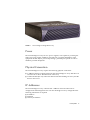
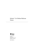
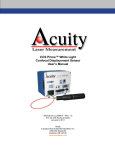
The Single Array configuration is shown in FIGURE 1.
2
Sun StorEdge™ T3 Single Storage Array Design and Installation • September 2000
FIGURE 1
Sun StorEdge T3 Single Disk Array
Power
The Sun StorEdge T3 Array has two power supplies, each capable of powering the
entire array. Each supply should be powered from a separate distribution. New
equipment should only be powered up during a planned quiet period in order to
minimize possible disruptions.
Physical Connection
The Sun StorEdge T3 Array requires the following physical connections:
■
■
A 10BaseT ethernet connection between the Sun StorEdge T3 Array and the local
area network to allow administration of the array.
A Fibre Channel (FC-AL) connection between the Sun StorEdge T3 Array and the
host for data access.
IP Addresses
The Sun StorEdge T3 Array controller has a 10BaseT network connection for
configuration and management. For each Sun StorEdge T3 Array configuration the
following information is required.
■
■
■
IP Address
Netmask
Gateway IP Address
Prerequisites
3
Systems Management
The Sun StorEdge T3 Array are supplied with Sun StorEdge Component Manager
software. This software will need to be installed on an appropriate host, such as a
systems management server or a systems administration server. It will be used to
monitor and manage the Sun StorEdge T3 Array and can route alerts to E-mail.
Some planning should be undertaken as to where the software will be installed and
where the alerts are to be sent.
The Sun StorEdge T3 Array can be configured to forward SNMP traps. If this is
applicable the destination TCP/IP address or machine name should be defined in
preparation for implementation.
Storage Layout Design
Volume Layout
A Sun StorEdge T3 Array controller can present a maximum of 2 LUNs (Logical Unit
Numbers), for example, c0t0d0, c0t0d1. The drives within the Sun StorEdge T3 Array
can be configured in to one or two volumes. A volume is restricted to be a minimum
of 2 disks.
The RAID 5 performance of the Sun StorEdge T3 Array is comparable to RAID 1 for
most workloads except small random write operations where RAID 1 performance is
approximately 20% better. Therefore, for most applications, a 7 + 1 disk (RAID 5), 1
disk hot spare configuration is recommended. In a high availability environment or
where the application mandates relatively small file systems, a Volume Manager
must be employed to break up the 112GB of usable space, assuming 18.2GB drives.
The Sun StorEdge T3 Array can also be ordered with 36.4GB drives.
Volume Manager
The disk space that results from the 7 + 1 configuration above is in the region of
112GB (assuming 18.2GB disks). This is difficult to manage as a single file system.
Partitioning the disk works well only if future requirements can be predicted. Since
this is rarely true, it adds no more value than leaving the disk as one slice, and it
could be argued that partitioning makes maintenance more difficult.
4
Sun StorEdge™ T3 Single Storage Array Design and Installation • September 2000
The best practice is to use VERITAS volume manager. This allows the disk to be
broken down into sub-disks, each of which can have a specific function, for example,
Index, Data, Logs and Archive. As the sub-disks are spread over all 8 physical disks,
I/O will be distributed evenly. VERITAS will allow the volumes to be grown or
reduced in size dynamically. All of which means a much more manageable,
maintainable, and available system.
Implementation
The Sun StorEdge T3 Array can be configured one of two ways.
1. Serial connection (mainly for use by service personnel)
2. Telnet configuration (uses rarp to assign an initial IP address)
The two methods are described below, followed by a common set of configuration
commands.
▼
Serial Connection
The serial connection is not required for administration tasks. However it will prove
useful if the Sun StorEdge T3 Array boot messages need to be observed. The cable
required for connection to the Sun StorEdge T3 Array does not ship with the array
but can be ordered as part number F370-4119.
1. Connect to the Sun StorEdge T3 Array from a Solaris™ Operating Environment
host, serial cable connected to port B, by entering:
% tip –9600 /dev/ttyb
Ensure the connection is made at 9600 baud, 8 bits (default) and no parity (default).
2. If /etc/remote is unmodified from its installation configuration, you can also
enter:
% tip hardwire
If you are configuring the Sun StorEdge T3 Array using the serial connection skip
the next section and proceed to the “Sun StorEdge T3 Array Configuration“section.
Implementation
5
▼
Telnet Configuration
The configuration method given below uses the local files on a single host. It could
also be achieved via a distributed naming service such as NIS.
Note – You must be root to perform these procedures.
1. Edit /etc/ethers.
Edit the /etc/ethers file and enter the Ethernet MAC address and the name that
you have chosen for the Sun StorEdge T3 Array disk tray. For example, to add a
machine named blueprint with a MAC address of 00:20:f2:00:09:07, you
would enter:
00:20:f2:00:09:07
blueprint
Note – The Ethernet MAC address of each Sun StorEdge T3 Array is recorded on a
pull out tab located at the front left hand side of the array behind the removable
front cover.
2. Edit /etc/hosts.
Edit the /etc/hosts file and enter the IP address that has been assigned to the Sun
StorEdge T3 Array disk tray. For example, to add a machine named blueprint
with an IP address of 10.0.1.182, you would enter:
10.0.1.182
blueprint
3. View /etc/netconfig.
The file /etc/netconfig should be viewed to confirm that a “-“exists for
<nametoaddr_libs> of the inet (udp, tcp, rawip) transports. This is the default.
The example following shows the correct configuration. If the configuration is not
correct, use a text editor to correct the file.
6
Sun StorEdge™ T3 Single Storage Array Design and Installation • September 2000
#
# The "Network Configuration" File.
#
# Each entry is of the form:
#
#
<network_id> <semantics> <flags> <protofamily> <protoname> \
#
<device> <nametoaddr_libs>
#
# The "-" in <nametoaddr_libs> for inet family transports indicates
# redirection to the name service switch policies for "hosts" and
# "services". The "-" may be replaced by nametoaddr libraries that
# comply with the SVr4 specs, in which case the name service switch
# will not be used for netdir_getbyname, netdir_getbyaddr,
# gethostbyname, gethostbyaddr, getservbyname, and getservbyport.
# There are no nametoaddr_libs for the inet family in Solaris anymore.
#
udp
tpi_clts
v
inet
udp
/dev/udp
tcp
tpi_cots_ord v
inet
tcp
/dev/tcp
rawip
tpi_raw
inet
/dev/rawip
ticlts
tpi_clts
v
loopback /dev/ticlts
straddr.so
ticotsord tpi_cots_ord v
loopback /dev/ticotsord straddr.so
ticots
tpi_cots
v
loopback /dev/ticots
straddr.so
4. Edit /etc/nsswitch.conf
The default configuration is to use NIS for hosts and ethers address resolution. The
following lines appear in /etc/nsswitch.conf:
hosts: nis [NOTFOUND=return] files
ethers: nis [NOTFOUND=return] files
If NIS is not to be used during the initial setup, edit the file so that the local files are
referenced as follows, ensure the information is added to the naming service later:
hosts: nis files [NOTFOUND=return]
ethers: nis files [NOTFOUND=return]
5. Start the RARP daemon (rarpd).
The default configuration results in the RARP daemon not being started at boot time
by the script /etc/rc3.d/S15nfs.server.
a. To check if rarpd is running enter the following command:
# pgrep rarpd
Implementation
7
b. If rarpd is not running it can be started by entering the following command:
# /usr/sbin/in.rarpd –a &
This command does not need to be executed on subsequent reboots; once the Sun
StorEdge T3 Array has acquired its IP address, it is stored permanently.
6. Ensure that the partner group cables are not connected to the Sun StorEdge T3
Array.
7. Power ON the Sun StorEdge T3 Array.
Once the Sun StorEdge T3 Array has booted it can be contacted using TELNET and
specifying the host name of the Sun StorEdge T3 Array.
Sun StorEdge T3 Array Configuration
In the previous section we provided instructions on connecting to the Sun StorEdge
T3 Array. This section provides instructions on configuring the following items on
the Sun StorEdge T3 Array.
■
■
■
■
■
■
■
Root Password
IP configuration
Time
Firmware revision confirmation
Volume creation
Device creation
Filesystem creation
Note – All procedures assume you are already connected to the Sun StorEdge T3
Array using one of the procedures described in the previous section.
▼
Root Password
Set the root password of the Sun StorEdge T3 Array with the passwd command.
:/:<1> passwd
Note – Initially there is no root password set on the Sun StorEdge T3 Array. To log
on, use the username root and press return when prompted for the password.
8
Sun StorEdge™ T3 Single Storage Array Design and Installation • September 2000
▼
IP Configuration
Set the IP address, gateway and netmask on the Sun StorEdge T3 Array using the
set ip, set gateway, set netmask, and set hostname commands, as shown
below.
Note – You do not need to use the set ip command if you have already set the IP
address previously using RARP.
:/:<2> set ip www.xxx.yyy.zzz
:/:<3> set gateway www.vvv.uuu.ttt
:/:<4> set netmask aaa.bbb.ccc.ddd
:/:<5> set hostname hostname
▼
Time Settings
1. Set the date on the Sun StorEdge T3 Array using the date command.
hostname:/:<6>date yyyymmddHHMM.SS
2. Set the time zone as an offset from Greenwich Mean Time (GMT), also know as
Universal Time Coordinated (UTC) using the tzset command with the
appropriate off-set substituted, for example -0800.
hostname:/:<7>tzset –0800
The above command would be issued if the Sun StorEdge T3 Array were located on
the West Coast of the United States of America.
▼
Confirm Firmware Revisions
Use the ver and fru list commands to list the version and patches on the Sun
StorEdge T3 Array.
hostname:/:<8>ver
hostname:/:<9>fru list
Check http://www.sunsolve.sun.com to make sure you have the latest
versions. Note that SunSolveSM has a specific Storage Product Patches page
(PatchPro Interactive) where Storage Product, Operating System and disk drive type
can be entered to produce a list of relevant patches.
Sun StorEdge T3 Array Configuration
9
▼
Volume Creation
Use the procedure below to create a 7 + 1 disk (RAID 5) volume with 1 hot spare.
1. Telnet to the Sun StorEdge T3 Array, if you are not already connected, and log in
as root.
2. Unmount and remove the original volume using the vol unmount and vol
remove commands.
WARNING: The vol remove command will destroy any data on the volume
hostname:/:<1>vol unmount v0
hostname:/:<2>vol remove v0
3. Create a 7+1 (RAID 5) disk using the vol add command.
hostname:/:<3>vol add v0 data u1d1-8 raid 5 standby u1d9
4. Initialize and mount the volume using the vol init and vol mount commands.
hostname:/:<4>vol init v0 data rate 16
hostname:/:<5>vol mount v0
▼
Device Configuration
On operating environments prior to the Solaris 8 Operating Environment new
devices must be manually configured on the host.
1. The system must be rebooted with the –r flag.
{0} ok boot –r
On the Solaris 8 Operating Environment the new devices will be automatically
recognized and configured by the devfseventd and devfsadmd daemons.
2. The format and vxdctl commands are then executed as follows to complete the
configuration.
a. Label the volume that has been created on the Sun StorEdge T3 Array using the
format command. This will allow VERITAS Volume Manager to recognize the
new device.
b. If VERITAS Volume Manager is being used, and is already configured use the
vxdctl command to add the new device to its configuration.
# vxdctl enable
Instructions for configuring a new installation of VERITAS Volume Manager appear
later in the “Creating Disk Groups” section.
10
Sun StorEdge™ T3 Single Storage Array Design and Installation • September 2000
▼
File System Creation
VERITAS Volume Manager
If VERITAS Volume Manager is not being used, skip this section and proceed to the
next section, “Creating the File System.”
The Sun StorEdge T3 Array hardware is designed for high availability. To
complement this feature VERITAS Volume Manager should be used. The Volume
Manager will allow maintenance operations such as file system extension without
needing to take the file system off-line.
Configure the volumes within VERITAS Volume Manager by creating a disk group
and a volume as described in the following sections.
▼ Creating a Disk Group
If you have just installed VERITAS Volume Manager on the host, you must now
configure VERITAS Volume Manager using the vxinstall command, as shown
below. Refer to the VERITAS Volume Manager for Solaris Operating Environment
Installation Guide for more information of vxinstall.
# vxinstall
This configures VERITAS and allows disks to be added to the rootdg disk group. At
least one disk must belong to the rootdg disk group.
If VERITAS Volume Manager is already installed and configured on the host, add
the disks to a disk group using the vxdiskadd command.
# vxdiskadd target
where target can be c2 or c2t3 or c2t3d4 or c2 c3t5d1 or all
▼ Creating a Volume
Once the disk has been added to a disk group, a volume can be created from that
disk. Volume Manager will automatically select the disks comprising a volume
unless they are specified. Use the vxassist make command to create a volume
from a specific disk.
# vxassist make volume_name length diskname
For example,
# vxassist make data01 3g disk01
Sun StorEdge T3 Array Configuration
11
The above command will create a concatenated volume. To create a Striped
(RAID-0), RAID-5 or Mirrored (RAID-1) volumes see the vxassist man pages and
VERITAS Volume Manager Command Line Interface Administrator’s Guide. In this
instance, the Sun StorEdge T3 Array’s hardware takes care of the RAID-5 functions,
so a concatenated volume is the correct choice.
▼ Disabling VERITAS Volume Manager Hot Relocation
Although not strictly applicable to this configuration, as the Sun StorEdge T3 Array
hardware will handle hardware and data resilience, disabling hot relocation and
enabling hot sparing within VERITAS Volume Manager is very strongly
recommended.
Hot relocation attempts to relocate each subdisk of a failed disk. This can have
unpredictable and possibly undesirable results, for example both plexes of a mirror
on the same physical disk, as VERITAS will place the sub disks wherever it can find
free space within the pool of hot relocation spares.
Hot sparing in contrast substitutes a failed disk with an entire spare disk from the
pool of hot spares. This yields predictable results and more importantly a less
complex recovery procedure.
Hot relocation is enabled by default and can be disabled and hot sparing enabled by
editing the file /etc/rc2.d/S95vxvm-recover so that the last 10 lines of
/etc/rc2.d/S95vxvm-recover look as follows:
# start the watch daemon. This sends E-mail to the administrator
# any problems are found. To change the address used for sending
# problem reports, change the argument to vxrelocd.
# vxrelocd root &
# to enable hot sparing instead of hot relocation.
# (comment out vxrelocd before uncommenting vxspare)
vxsparecheck root &
exit 0
To enable the changes above without rebooting the machine stop the vxrelocd
daemon using the kill command and start the vxsparecheck daemon manually.
Execute the commands below to specify hot spares:
# /etc/vx/bin/vxdisksetup –i disk device name
# vxdg –g disk group name adddisk hotspare=disk device name
# vxedit –g disk group name set spare=on hotspare
▼ Creating the File System
When the volume has been created on the Sun StorEdge T3 Array a file system can
be created and mounted by the host.
12
Sun StorEdge™ T3 Single Storage Array Design and Installation • September 2000
1. Use format to partition the volume on the Sun StorEdge T3 Array unless a
volume has been created via VERITAS Volume Manager. Then create and mount
the file system, example commands are shown below.
# newfs –v /dev/rdsk/c5t1d0s2
# mount /dev/dsk/c5t1d0s2 /mnt
or if using VERITAS Volume Manager the paths will be as follows:
# newfs –v /dev/vx/rdsk/data01
# mount /dev/vx/dsk/data01 /mnt
2. Create directories for the permanent mount points and edit /etc/vfstab to
include the new file systems.
3. Complete the configuration by following the information in the “Management“
section.
Management
/etc/syslog.conf
Edit the /etc/syslog.conf file on the Sun StorEdge T3 Array so that the Sun
StorEdge T3 Array system events are logged to a suitable management host. An
example syslog.conf file is shown following.
# syslog.conf
# facility.level action
# messages to local syslog file
*.notice /syslog
# messages to syslog on another host
*.warn @remotehost
# messages sent as SNMP traps
*.warn | snmp_trap 10.1.6.201
1. Use FTP from either the Sun StorEdge T3 Array or on a host to transfer the
syslog.conf file to the host.
Management
13
2. Edit the syslog.conf file then FTP the file back to the Sun StorEdge T3 Array.
/etc/hosts
If you need to reference the management host in the file
/etc/syslog.conf by hostname rather than IP address, then the /etc/hosts file
on the Sun StorEdge T3 Array should be edited using the method described in the
previous section.
Sun StorEdge Component Manager
The Sun StorEdge T3 Array includes the Sun StorEdge Component Manager
software. The Sun StorEdge Component Manager Installation Guide and Release Notes
should be followed to install the Sun StorEdge Component Manager. The following
points should be noted from the installation of Component Manager 2.0 but should
be verified against later versions:
1. The directory /dev/es should exist prior to installation. If it does not, create the
directory and change the permissions to 755, as shown below.
# mkdir /dev/es
# chmod 755 /dev/es
2. If the Solaris 2.6 Operating Environment is being run then the SUNWses package
must be installed prior to the Sun StorEdge Component Manager installation.
a. Install all patches recommended by the Installation Guide and Release Notes.
b. Check for later patches at http://sunsolve.sun.com. Download and install the
appropriate patches.
c. Edit /etc/opt/SUNWesm/mo/hosts to add the IP address and name of the Sun
StorEdge T3 Arrays to be managed.
3. If you are using NIS, and Sun StorEdge Component Manager is installed on a
host that is not included in the NIS host tables, edit the file /etc/
nsswitch.conf so that the line referring to hosts looks as follows:
hosts: nis file [NOTFOUND=return]
If this is not done Component Manager will fail to start.
4. After the installation and startup of Sun StorEdge Component Manager, the
Management Console can be started with the esm_gui command.
# /usr/opt/SUNWesm/bin/esm_gui &
14
Sun StorEdge™ T3 Single Storage Array Design and Installation • September 2000
5. Configure Sun StorEdge Component Manager to route status messages to e-mail
addresses and Log files.
a. Select the Configuration tab on the main screen of the Sun StorEdge
Component Manager Management Console.
b. Enter the required e-mail addresses and Log file names.
6. To display a physical view of the Sun StorEdge T3 Array that graphically shows
the status of each FRU (Field Replaceable Unit) plus additional configuration and
status information, click on the FRU’s icon.
The component icons are found by double-clicking on Sun StorEdge Component
Manager in the Navigation pane.
References
Sun StorEdge T3 Administrator’s Guide
Sun StorEdge T3 Installation, Operation and Service Manual
VERITAS Volume Manager Command Line Interface for Solaris Administrator’s Guide
VERITAS Volume Manager for Solaris Installation Guide
Author’s Bio: Mark Garner
Mark Garner is a Systems Engineer for Enterprise Engineering at Sun Microsystems. Prior to joining
Sun, Mark spent three years as a Systems Architect specializing in Email and Office Automation
architectures and before this over eight years in systems administration. While at Sun Mark has focused
on the design and implementation of mission critical business and Internet application’s infrastructure
principally to provide for high availability and scalability.
References
15