1
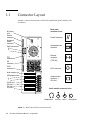
Sun™ Ultra™ 60 Reference Manual Sun Microsystems, Inc. 901 San Antonio Road Palo Alto, CA 94303-4900 U.S.A. 650-960-1300 Part No.: 805-1762-11 Revision A, August 2001 Send comments about this document to: [email protected] Copyright 2001 Sun Microsystems, Inc., 901 San Antonio Road, Palo Alto, CA 94303-4900 U.S.A. All rights reserved. This product or document is distributed under licenses restricting its use, copying, distribution, and decompilation. No part of this product or document may be reproduced in any form by any means without prior written authorization of Sun and its licensors, if any. Third-party software, including font technology, is copyrighted and licensed from Sun suppliers. Parts of the product may be derived from Berkeley BSD systems, licensed from the University of California. UNIX is a registered trademark in the U.S. and other countries, exclusively licensed through X/Open Company, Ltd. Sun, Sun Microsystems, the Sun logo, AnswerBook2, docs.sun.com, and Solaris are trademarks, registered trademarks, or service marks of Sun Microsystems, Inc. in the U.S. and other countries. All SPARC trademarks are used under license and are trademarks or registered trademarks of SPARC International, Inc. in the U.S. and other countries. Products bearing SPARC trademarks are based upon an architecture developed by Sun Microsystems, Inc. The Energy Star logo is a registered trademark of EPA. The OPEN LOOK and Sun™ Graphical User Interface was developed by Sun Microsystems, Inc. for its users and licensees. Sun acknowledges the pioneering efforts of Xerox in researching and developing the concept of visual or graphical user interfaces for the computer industry. Sun holds a non-exclusive license from Xerox to the Xerox Graphical User Interface, which license also covers Sun’s licensees who implement OPEN LOOK GUIs and otherwise comply with Sun’s written license agreements. Federal Acquisitions: Commercial Software—Government Users Subject to Standard License Terms and Conditions. DOCUMENTATION IS PROVIDED “AS IS” AND ALL EXPRESS OR IMPLIED CONDITIONS, REPRESENTATIONS AND WARRANTIES, INCLUDING ANY IMPLIED WARRANTY OF MERCHANTABILITY, FITNESS FOR A PARTICULAR PURPOSE OR NON-INFRINGEMENT, ARE DISCLAIMED, EXCEPT TO THE EXTENT THAT SUCH DISCLAIMERS ARE HELD TO BE LEGALLY INVALID. Copyright 2001 Sun Microsystems, Inc., 901 San Antonio Road, Palo Alto, CA 94303-4900 Etats-Unis. Tous droits réservés. Ce produit ou document est distribué avec des licences qui en restreignent l’utilisation, la copie, la distribution, et la décompilation. Aucune partie de ce produit ou document ne peut être reproduite sous aucune forme, par quelque moyen que ce soit, sans l’autorisation préalable et écrite de Sun et de ses bailleurs de licence, s’il y en a. Le logiciel détenu par des tiers, et qui comprend la technologie relative aux polices de caractères, est protégé par un copyright et licencié par des fournisseurs de Sun. Des parties de ce produit pourront être dérivées des systèmes Berkeley BSD licenciés par l’Université de Californie. UNIX est une marque déposée aux Etats-Unis et dans d’autres pays et licenciée exclusivement par X/Open Company, Ltd. Sun, Sun Microsystems, le logo Sun, AnswerBook2, docs.sun.com, et Solaris sont des marques de fabrique ou des marques déposées, ou marques de service, de Sun Microsystems, Inc. aux Etats-Unis et dans d’autres pays. Toutes les marques SPARC sont utilisées sous licence et sont des marques de fabrique ou des marques déposées de SPARC International, Inc. aux Etats-Unis et dans d’autres pays. Les produits portant les marques SPARC sont basés sur une architecture développée par Sun Microsystems, Inc. L’interface d’utilisation graphique OPEN LOOK et Sun™ a été développée par Sun Microsystems, Inc. pour ses utilisateurs et licenciés. Sun reconnaît les efforts de pionniers de Xerox pour la recherche et le développement du concept des interfaces d’utilisation visuelle ou graphique pour l’industrie de l’informatique. Sun détient une licence non exclusive de Xerox sur l’interface d’utilisation graphique Xerox, cette licence couvrant également les licenciés de Sun qui mettent en place l’interface d’utilisation graphique OPEN LOOK et qui en outre se conforment aux licences écrites de Sun. LA DOCUMENTATION EST FOURNIE “EN L’ETAT” ET TOUTES AUTRES CONDITIONS, DECLARATIONS ET GARANTIES EXPRESSES OU TACITES SONT FORMELLEMENT EXCLUES, DANS LA MESURE AUTORISEE PAR LA LOI APPLICABLE, Y COMPRIS NOTAMMENT TOUTE GARANTIE IMPLICITE RELATIVE A LA QUALITE MARCHANDE, A L’APTITUDE A UNE UTILISATION PARTICULIERE OU A L’ABSENCE DE CONTREFAÇON. Contents Preface xi How This Book Is Organized Related Documents 1. xi xii Back Panel Connectors 1-1 1.1 Connector Layout 1-2 1.2 Serial Connectors 1-3 1.3 Parallel Connector 1.4 Keyboard/Mouse Connector 1.5 Media Independent Interface (MII) Connector 1.6 1.7 1-4 1-5 1.5.1 MII Cable-Type Connectivity 1.5.2 External Cable Lengths 1.5.3 External Transceivers 1-7 1-7 1-7 Twisted-Pair Ethernet (TPE) Connector 1.6.1 TPE Cable-Type Connectivity 1.6.2 External UTP-5 Cable Lengths SCSI Connector 1-6 1-8 1-8 1-9 1-9 1.7.1 SCSI Implementation 1-10 1.7.2 SCSI Cabling Procedure 1-14 Contents iii 1.7.3 2. 3. 4. SCSI-2 (Fast/Wide SCSI) External Devices 1.8 Audio Ports 1.9 Audio Specifications 1.10 Graphics Card 13W3 Video Connector 1-16 1-18 Modem Setup Specifications 2-1 2.1 Setting Up the Modem 2-1 2.2 Serial Port Speed Change 2.3 Recommendations 1-19 2-2 2-2 2.3.1 Cable 2-2 2.3.2 Modem Switch Settings (AT Commands) Motherboard Jumpers Identifying Jumpers 3.2 Flash PROM Jumpers 3.3 Serial Port Jumpers System Specifications 2-3 3-1 3.1 3-3 3-4 3-5 4-1 4.1 Power Specifications 4.2 Environmental Specifications 4.3 Physical Specifications 4.4 Memory Mapping 4.5 1-15 4-1 4-2 4-3 4-4 4.4.1 DIMM Installation Guidelines 4.4.2 DIMM Banks and Slots PCI Card Slot Specifications 4-4 4-4 4-6 4.5.1 Locating the PCI Card Slots 4-6 4.5.2 PCI Card Slot Operating Frequencies 4-8 Contents iv Figures FIGURE 1-1 Back Panel Switches and Connectors FIGURE 1-2 DB-25 Serial Connectors 1-3 FIGURE 1-3 DB-25 Parallel Connector 1-4 FIGURE 1-4 DIN-8 Keyboard/Mouse Connector 1-5 FIGURE 1-5 40-Pin Miniature-D MII Connector FIGURE 1-6 RJ-45 TPE Connector FIGURE 1-7 68-Pin SCSI Connector FIGURE 1-8 Configuration for the SCSI Bus FIGURE 1-9 SCSI Subassembly Functional Block Diagram FIGURE 1-10 Connecting External Mass Storage Devices FIGURE 1-11 Audio Port Locations 1-16 FIGURE 1-12 13W3 Video Connector 1-19 FIGURE 3-1 Jumper Locations on the Motherboard 3-2 FIGURE 3-2 Identifying Jumper Pins FIGURE 4-1 Ultra 60 System Enclosure Physical Dimensions 4-3 FIGURE 4-2 Map of DIMM Banks and Slots on Motherboard FIGURE 4-3 PCI Card Slot Locations on the System Unit Back Panel FIGURE 4-4 PCI Card Slot Locations on the Motherboard 4-7 1-2 1-6 1-8 1-9 1-11 1-13 1-15 3-3 4-5 4-6 Figures vii viii Sun Ultra 60 Reference Manual • August 2001 Tables TABLE 1-1 RS-423/RS-232 Serial Connector Pinouts 1-3 TABLE 1-2 Parallel Connector Pinouts 1-4 TABLE 1-3 Keyboard/Mouse Connector Pinouts TABLE 1-4 MII Connector Pinouts TABLE 1-5 MII External Cable Lengths TABLE 1-6 MII Connectivity: Supported Transceivers TABLE 1-7 TPE Connector Pinouts 1-8 TABLE 1-8 TPE UTP-5 Cable Lengths 1-9 TABLE 1-9 68-Pin SCSI Connector Pinouts 1-9 TABLE 1-10 SCSI Target Devices 1-12 TABLE 1-11 Determining SCSI Bus Length 1-14 TABLE 1-12 Audio Port Signals 1-16 TABLE 1-13 Audio Port Functions TABLE 1-14 1-5 1-6 1-7 1-7 1-17 Audio Inputs and Output 1-18 TABLE 1-15 Internal Monaural Speaker Specifications 1-18 TABLE 1-16 13W3 Video Connector Pinouts TABLE 3-1 User-Configurable Jumpers 3-3 TABLE 3-2 Flash PROM Jumper Settings 3-4 TABLE 3-3 Serial Port Jumper Settings TABLE 4-1 Power Specifications 1-19 3-5 4-1 Tables ix TABLE 4-2 Power Supply Outputs 4-1 TABLE 4-3 Environmental Specifications: Operating TABLE 4-4 Environmental Specifications: Nonoperating 4-2 TABLE 4-5 Dimensions and Weight 4-3 TABLE 4-6 DIMM Banks and Slots TABLE 4-7 PCI Card Slot Operating Frequencies 4-2 4-4 4-8 Tables x Preface The Sun Ultra 60 Reference Manual contains information about the use and maintenance of an Ultra™ 60 system. It also includes information about configuring system communitations settings. The revision of the Sun Ultra 60 Reference Manual provided here is the latest version of the document, and includes information that may be different from that contained in the reference documentation originally shipped with the Sun Ultra 60 system. How This Book Is Organized Chapter 1, “Back Panel Connectors,” shows the location of each back panel connector and gives the pinouts for each connector. Chapter 2, “Modem Setup Specifications,” gives modem settings for Ultra 60 systems used in specific network telecommunication applications. Chapter 3, “Motherboard Jumpers,” gives the locations and pin definitions of userconfigurable motherboard jumpers. Chapter 4, “System Specifications,” gives system requirements about power and environment, and also gives system dimension, weight, memory mapping, and peripheral component interconnect (PCI) card slot specifications. xi Related Documents The following documents contain topics that relate to the information in the Sun Ultra 60 Reference Manual. TABLE P-1 Related Documents Application Title Part Number Installation Sun Ultra 60 Installation Guide 805-1707 Service Sun Ultra 60 Service Manual 805-1709 Accessing Sun Documentation Online A broad selection of Sun system documentation is located at: http://www.sun.com/products-n-solutions/hardware/docs A complete set of Solaris documentation and many other titles are located at: http://docs.sun.com Ordering Sun Documentation Fatbrain.com, an Internet professional bookstore, stocks select product documentation from Sun Microsystems, Inc. For a list of documents and how to order them, visit the Sun Documentation Center on Fatbrain.com at: http://www.fatbrain.com/documentation/sun xii Sun Ultra 60 Reference Manual • August 2001 Sun Welcomes Your Comments Sun is interested in improving its documentation and welcomes your comments and suggestions. You can email your comments to Sun at: [email protected] Please include the part number (805-1762-11) of your document in the subject line of your email. Preface xiii xiv Sun Ultra 60 Reference Manual • August 2001 CHAPTER 1 Back Panel Connectors This chapter contains specifications for the back panel connectors on the Ultra 60 system. 1-1 1.1 Connector Layout FIGURE 1-1 shows the locations of Ultra 60 system back panel switches and connectors. Back panel connector icons: AC power inlet Parallel connector Parallel connector Keyboard/ mouse connector Keyboard/mouse connector Serial connectors B A Ethernet connector (TPE, MII) TPE connector MII connector SCSI connector SCSI connector Audio module slot UPA graphics slots 0 1 Graphics/video connector — UPA slot PCI66 slot 1 PCI slot 2 PCI slot 3 PCI slot 4 Audio module connector icons: Headphones FIGURE 1-1 1-2 Back Panel Switches and Connectors Sun Ultra 60 Reference Manual • August 2001 Line Out Line In Microphone 1.2 Serial Connectors 13 1 25 14 13 1 25 14 B A FIGURE 1-2 DB-25 Serial Connectors TABLE 1-1 RS-423/RS-232 Serial Connector Pinouts Pin Function I/O Signal Description 1 none none Not connected 2 TxD O Transmit Data 3 RxD I Receive Data 4 RTS O Ready To Send 5 CTS I Clear To Send 6 DSR I Data Set Ready 7 Gnd 8 DCD I Data Carrier Detect 9–14 none none Not connected 15 TRxC I Transmit Clock 16 none none Not connected 17 RTxC I Receive Clock 18–19 none none Not connected 20 DTR O Data Terminal Ready 21-23 none none Not connected 24 TxC O Transmit Clock 25 none none Not connected Signal Ground Note: For information about serial port jumpers on the Ultra 60 system motherboard, see Section 4.1, “Identifying Jumpers,” and Section 4.3, “Serial Port Jumpers.” Chapter 1 Back Panel Connectors 1-3 1.3 Parallel Connector 13 1 25 1-4 14 FIGURE 1-3 DB-25 Parallel Connector TABLE 1-2 Parallel Connector Pinouts Pin Description Pin Description 1 Data_Strobe_L 14 AFXN_L 2 Data0 15 ERROR_L 3 Data1 16 RESET_L 4 Data2 17 IN_L 5 Data3 18 Ground 6 Data4 19 Ground 7 Data5 20 Ground 8 Data6 21 Ground 9 Data7 22 Ground 10 ACK_L 23 Ground 11 BUSY 24 Ground 12 PERROR 25 Ground 13 SELECT_L Sun Ultra 60 Reference Manual • August 2001 1.4 Keyboard/Mouse Connector 7 8 5 6 4 2 3 1 FIGURE 1-4 DIN-8 Keyboard/Mouse Connector TABLE 1-3 Keyboard/Mouse Connector Pinouts Pin Description Pin Description 1 Ground 5 Keyboard_Data_ Out_L 2 Ground 6 Keyboard_Data_ In_L 3 Power 7 Poweron_L 4 Mouse_Data_In_L 8 Power Note – All signals are standard TTL levels. The +5V supply is fuse-protected. Chapter 1 Back Panel Connectors 1-5 1.5 1-6 Media Independent Interface (MII) Connector 20 1 40 21 FIGURE 1-5 40-Pin Miniature-D MII Connector TABLE 1-4 MII Connector Pinouts Pin Function Pin Function 1 +5V 18 COL 2 MDIO 19 CRS 3 MDC 20 +5V 4 RXD<3> 21 +5V 5 RXD<2> 22 Signal Ground 6 RXD<1> 23 Signal Ground 7 RXD<0> 24 Signal Ground 8 RX_DV 25 Signal Ground 9 RX_CLK 26 Signal Ground 10 RX_ER 27 Signal Ground 11 TX_ER 28 Signal Ground 12 TX_CLK 29 Signal Ground 13 TX_EN 30 Signal Ground 14 TXD<0> 31 Signal Ground 15 TXD<1> 32 Signal Ground 16 TXD<2> 33 Signal Ground 17 TXD<3> 34 Signal Ground 35 Ground 38 Signal Ground 36 Ground 39 Signal Ground 37 Ground 40 +5V Sun Ultra 60 Reference Manual • August 2001 1.5.1 MII Cable-Type Connectivity The following types of Ethernet cables can be connected to the 40-pin MII connector when using specific interface conversion devices: ■ ■ ■ 1.5.2 Shielded twisted-pair (STP) Unshielded twisted-pair (UTP) Fiber (connected to an external transceiver) External Cable Lengths TABLE 1-5 MII External Cable Lengths Maximum Length (Metric) Maximum Length (English) All external MII 0.5 meter 20 inches UTP-5, “data grade” 10BASE-T 100 meters* 109 yards* UTP-5, “data grade” 100BASE-T 100 meters* 109 yards* Cable Type Application(s) 40-conductor (20 signal-ground STP) * IEEE 802.3 1.5.3 External Transceivers TABLE 1-6 MII Connectivity: Supported Transceivers Cable Type Transceiver Model and Application Transceiver Manufacturer Thick coaxial-cable Ethernet XF467A, MII to AUI, 10BASE-5 Sun MII-to-AUI UTP-3, “voice grade” CT4-1030, 100BASE-T4 Canary Communications Fiber 6211 Micro, Fast Ethernet, 100BASE-FX Transcast Corporation Fiber CFX-107X, Fast Ethernet, 100BASE-FX Canary Communications Chapter 1 Back Panel Connectors 1-7 1.6 Twisted-Pair Ethernet (TPE) Connector 8 1.6.1 1 FIGURE 1-6 RJ-45 TPE Connector TABLE 1-7 TPE Connector Pinouts Pin Description Pin Description 1 Transmit Data + 5 Common Mode Termination 2 Transmit Data - 6 Receive Data - 3 Receive Data + 7 Common Mode Termination 4 Common Mode Termination 8 Common Mode Termination TPE Cable-Type Connectivity The following types of twisted-pair Ethernet cables can be connected to the 8-pin TPE connector: ■ For 10BASE-T applications, UTP cable: ■ ■ ■ ■ 1-8 Category 3 (UTP-3, “voice grade”) Category 4 (UTP-4) Category 5 (UTP-5, “data grade”) For 100BASE-T applications, UTP-5, “data grade” cable Sun Ultra 60 Reference Manual • August 2001 1.6.2 External UTP-5 Cable Lengths TABLE 1-8 TPE UTP-5 Cable Lengths Cable Type Application(s) Maximum Length (Metric) Maximum Length (English) UTP-5, “data grade” 10BASE-T 100 meters* 109 yards* UTP-5, “data grade” 100BASE-T 100 meters* 109 yards* * IEEE 802.3 1.7 SCSI Connector 34 68 1 35 FIGURE 1-7 68-Pin SCSI Connector TABLE 1-9 68-Pin SCSI Connector Pinouts Pin Signal Name Pin Signal Name 1 Ground 35 -DB<12> 2 Ground 36 -DB<13> 3 Ground 37 -DB<14> 4 Ground 38 -DB<15> 5 Ground 39 -PAR<1> 6 Ground 40 -DB<0> 7 Ground 41 -DB<1> 8 Ground 42 -DB<2> 9 Ground 43 -DB<3> 10 Ground 44 -DB<4> 11 Ground 45 -DB<5> 12 Ground 46 -DB<6> Chapter 1 Back Panel Connectors 1-9 TABLE 1-9 68-Pin SCSI Connector Pinouts Pin Signal Name Pin Signal Name 13 Ground 47 -DB<7> 14 Ground 48 -PAR<0> 15 Ground 49 Ground 16 Ground 50 TERM.DIS 17 TERMPWR 51 TERMPWR 18 TERMPWR 52 TERMPWR 19 Not connected 53 Reserved 20 Ground 54 Ground 21 Ground 55 -ATN 22 Ground 56 Ground 23 Ground 57 -BSY 24 Ground 58 -ACK 25 Ground 59 -RST 26 Ground 60 -MSG 27 Ground 61 -SEL 28 Ground 62 -CD 29 Ground 63 -REQ 30 Ground 64 -IO 31 Ground 65 -DB<8> 32 Ground 66 -DB<9> 33 Ground 67 -DB<10> 34 Ground 68 -DB<11> Note – All signals shown in 1.7.1 TABLE 1-9 are active low. SCSI Implementation The Ultra 60 implements a small computer system interface (SCSI) Fast-20 (UltraSCSI) parallel interface bus. The UltraSCSI provides the following: ■ 1-10 Efficient peer-to-peer I/O bus devices Sun Ultra 60 Reference Manual • August 2001 ■ Mechanical, electrical, and timing specification definition that support transfer rates of 20 or 40 Mbytes per second (corresponding to the data path width of an 8-bit, or 16-bit bus, respectively). ■ Peak bandwidth of 40 Mbytes per second (with implemented 16-bit bus width). The internal SCSI bus is terminated at each end. One set of terminators is located close to the CD-ROM drive connector on the CD-ROM SCSI card. A second set of terminators is located close to the 68-pin external SCSI connector. FIGURE 1-8 shows the SCSI bus configuration. CD-ROM drive (8-bit) T Disk 1 (UltraSCSI) Disk 0 (UltraSCSI) Host adapter (UltraSCSI) T T SCSI bus External to chassis Internal SCSI bus FIGURE 1-8 1.7.1.1 External devices (UltraSCSI) Configuration for the SCSI Bus Host Adapter The host adapter is a Symbios Logic PCI-SCSI I/O processor IC. The host adapter and all target devices comply with the Fast-20 single-ended drivers and receivers characteristics. The electrical characteristics of the output buffers include: ■ Vol (output low) equals 0 to 0.5 Vdc with Iol at 48 mA (signal asserted) ■ Voh (out high) equals 2.5 to 3.7 Vdc (signal negated) ■ trise (rising slew rate) equals 520 mV per nanosecond maximum (0.7 to 2.3 Vdc) ■ tfall (falling slew rate) equals 520 mV per nanosecond maximum (2.3 to 0.7 Vdc) Chapter 1 Back Panel Connectors 1-11 The Fast-20 electrical characteristics for the host adapter and target device include: 1.7.1.2 ■ Vil (input low) equals 1.0 Vdc maximum (signal true) ■ Vih (input high) equals 1.9 Vdc minimum (signal false) ■ Iil (input low current) equals +/- 20 µA at Vi equals 0.5 Vdc ■ Iih (input high current) equals +/- 20 µA at Vi equals 2.7 Vdc ■ Minimum input hysteresis equals 0.3 Vdc Supported Target Devices The SCSI subsystem supports a maximum of four internal devices, including the host adapter. The CD-ROM drive is a narrow device. A unipack with one drive or a six-pack, accommodating six drives, can be used as external devices. TABLE 1-10 lists the target devices supported by the SCSI subsystem. TABLE 1-10 1.7.1.3 SCSI Target Devices Target Device Comment Internal disks Up to two 3.5-inch x 1.6-inch disks (4.2, or 9.1-Gbyte). All internal disks are UltraSCSI-compliant. Internal CD-ROM drive Optional 644-Mbyte SunCD 12X speed; photo CD compatible. Headphone jack with volume control. CD-ROM drive is a narrow SCSI device. Internal tape drive(s) Refer to product guide. External SPARCstorage UniPack Refer to product guide. External SPARCstorage SixPack .Refer to product guide. External Cables External UltraSCSI-compliant SCSI cables have an impedance of 90 ohm (+/- 6 ohm) and are required for UltraSCSI interface. Sun’s implimentation of UltraSCSI requires that the total SCSI bus length be limited to no more than approximately 20 feet (6 meters) with up to 12 Sun compensated devices. Due to the considerably short bus length, an approximale 32-inch (0.8-meter) UltraSCSI-compliant external cable is supported (part number 530-2883) in addition to an approximale 6.5-foot (2-meter) UltraSCSI-compliant external cable (part number 530-2884). 1-12 Sun Ultra 60 Reference Manual • August 2001 1.7.1.4 Internal SCSI Subassembly The internal SCSI subassembly consists of two cable assemblies and two SCSI cards. The SCSI subassembly is attached to the motherboard using an insulation displacement connector (IDC) receptacle attached to a 80-conductor cable. In addition to the SCSI signals, the 80-conductor cable carries diskette drive and system LED signals to the SCSI backplane card. The IDC receptacle mates with a right angle plug that is mounted on the motherboard. The 80-conductor cable attaches on the other end to the SCSI backplane card with another IDC connector. The SCSI backplane card incorporates two SCA-2 connectors for mounting the hard drives, a four-circuit power connector to supply 5 Vdc and 12 Vdc power to the hard drives, a 34-pin diskette drive signal connector, and a green, right-angle LED. A 68-conductor cable exits the SCSI backplane card, carrying 27 SCSI signals and the Termpower to the internal CD-ROM drive (or tape drive). The SCSI backplane card houses the CD-ROM drive connector and three SCSI bus terminators. The Termpower is routed through the SCSI subassembly to connect to the terminators on the SCSI backplane card in support of the multi-host configuration. FIGURE 1-9 functionally shows the internal SCSI subassembly. 68-pin external SCSI connector 68-pin cable IDC connector CD-ROM drive connector SCA-2 connector SCSI bus terminator (3) IDC connector Motherboard SCA-2 connector (2) Drive power Diskette signal SCSI controller IDC connector 80-conductor cable Test edge connector IDC receptacle connector SCSI bus Board-mounted right-angle IDC plug FIGURE 1-9 SCSI Subassembly Functional Block Diagram Chapter 1 Back Panel Connectors 1-13 1.7.1.5 SCSI ID Selection The motherboard host adapter is assigned the SCSI identification of 7 for both ports. The two internal drives attached to the SCA-2 connectors have a SCSI identification of 0 and 1, while the CD-ROM has an identification of 6. 1.7.2 SCSI Cabling Procedure 1. Count the number of SCSI devices on the system SCSI bus. Be sure to count the host adapter as a SCSI device. 2. Determine the total SCSI bus length. TABLE 1-11 Determining SCSI Bus Length SCSI Implementation Bus Width Data Transfer Rate, Mbytes/s Number of Devices SCSI Bus Length SCSI-2, Fast 8 bits 10 1–8 6.0 meters SCSI-2, Fast/Wide 16 bits 20 1–8 6.0 meters SCSI-3 Parallel Interface, Fast-20 Wide (UltraSCSI) (WideUltra) 16 bits 40 1–4 3.0 meters2 SCSI-3 Parallel Interface, Fast-20 Wide (UltraSCSI) (WideUltra) 16 bits 40 5–81 1.5 meters2 1. The maximum number of single-ended/differential SCSI devices is 16. 2. The effective internal SCSI bus length of the Ultra 60 system unit is 0.9 meter. 3. Verify the cable type used to connect external SCSI devices. You must use Fast-20 SCSI cable(s). 4. Ensure that the total SCSI cable length does not exceed the permissible total SCSI bus length. An Ultra 60 system enables the use of a single 0.8 meter (32 inch) Fast-20 SCSI cable to a single external SCSI-3 parallel interface, Fast-20 Wide (UltraSCSI, WideUltra) device or device cluster. 1-14 Sun Ultra 60 Reference Manual • August 2001 1.7.3 SCSI-2 (Fast/Wide SCSI) External Devices If you connect SCSI-2 (Fast/Wide SCSI, 20 Mbytes data transfer rate) external devices to an Ultra 60 system, follow these cabling and configuration guidelines to ensure proper device addressing and operation: ■ If all external mass storage devices use 68-pin connectors, connect all non-Sun devices to the Ultra 60 system first and follow them with Sun devices. Sun devices use autotermination. ■ If external mass storage devices consist of 68-pin Sun devices and 50-pin devices, connect the Sun 68-pin devices to the Ultra 60 system first and terminate the daisy chain with the 50-pin device and its terminator. ■ The total SCSI bus length for all SCSI devices (internal and external) is 6.0 meters (19.7 feet). See FIGURE 1-10 for a summary of cabling and configuration guidelines. Sun device Non-Sun device Ultra 60 system 68—68 68—68 68—68 Sun device Non-Sun device Ultra 60 system Sun device 50-pin device T 68—50 68—68 FIGURE 1-10 Adapter cable 68—68 Terminator Connecting External Mass Storage Devices Chapter 1 Back Panel Connectors 1-15 1.8 Audio Ports Audio Module Connector Icons: Headphones FIGURE 1-11 Line Out Line In Microphone Audio Port Locations All audio ports use EIA standard 3.5-mm/0.125-inch jacks. TABLE 1-12 1-16 Audio Port Signals Plug Headphones Line Out Line In Microphone Tip Left Channel Left Channel Left Channel Left Channel Ring (Center) Right Channel Right Channel Right Channel Right Channel Shield Ground Ground Ground Ground Sun Ultra 60 Reference Manual • August 2001 TABLE 1-13 Audio Port Functions Port Function Headphones Connects stereophonic headphones for private listening of audio output Line Out Connects the system audio output to an external stereophonic amplifier Line In Connects external stereophonic audio sources such as a compact disc player or cassette tape player to the system Microphone Connects the SunMicrophone II (or other suitable microphone1) to the system 1. The Ultra 60 system microphone port accepts stereophonic input; however, the Sun Microphone II is a monophonic device. Note also that the older SunMicrophone is not compatible with the Ultra 60 system. Chapter 1 Back Panel Connectors 1-17 1.9 Audio Specifications The microphone input specifications are designed for the SunMicrophone II or equivalent. TABLE 1-14 Stereo I/Os Specifications Line In 3.3V peak (nominal), 9.2 kΩ input impedance Frequency Response 20 Hz–17 kHz +/- 1 dB Microphone Input 35 mV peak (nominal), 2.21 kΩ input impedance Headphones Output 0.84V peak (nominal), 9Ω output impedance; headphone impedance may vary from 9Ω to 1 kΩ. Line Out 1.4V peak (nominal), 220Ω output impedance TABLE 1-15 1-18 Audio Inputs and Output Internal Monaural Speaker Specifications Speaker Specifications Power Output 1W average, 2W peak Distortion 0.02%, typical at 1 kHz Impedance 16Ω +/- 15% Frequency Response 170 Hz–20 kHz +/- 6 dB Sun Ultra 60 Reference Manual • August 2001 1.10 Graphics Card 13W3 Video Connector 1 A1 6 FIGURE 1-12 5 10 A2 A3 13W3 Video Connector The graphics card for your system provides the 13W3 video connector for transmitting video output signals from the system unit to the monitor. TABLE 1-16 13W3 Video Connector Pinouts Pin Function I/O Level A1 Red O Analog A2 Green O Analog A3 Blue O Analog 1 Serial Read 2 Vert Sync O TTL 3 Sense <0> I TTL 4 Ground 5 Comp Sync O TTL 6 Horiz Sync O TTL 7 Serial Write 8 Sense <1> I TTL 9 Sense <2> I TTL 10 Ground TTL GND TTL GND Chapter 1 Back Panel Connectors 1-19 1-20 Sun Ultra 60 Reference Manual • August 2001 CHAPTER 2 Modem Setup Specifications 2.1 Setting Up the Modem Any modem compatible with CCITT V.24 can be connected to the Ultra 60 serial ports. Modems can be set up to function in one of three ways: ■ ■ ■ Dial out only Dial in only Bidirectional calls To set up your modem: 1. Become superuser and type admintool. % su Password: # admintool 2. Click Serial Port Manager. 3. Select Port a or Port b for your modem connection. 4. Click Edit. The Serial Port Manager: Modify Service window is displayed. 5. Choose the Expert level of detail. 6. From the Use Template menu, choose one of the following: ■ ■ ■ Modem - Dial-Out only Modem - Dial-In Only Modem - Bidirectional 7. Click Apply. 2-1 8. Set your modem auto-answer switch to one of the following: ■ ■ ■ 2.2 Off – Dial-Out Only On – Dial-In Only On – Bidirectional Serial Port Speed Change To change the speed of a serial port, you must edit the /etc/remote file as follows: 1. Become superuser, and type cd /etc. % su Password: # cd /etc 2. Type vi remote. 3. Type tip speed device-name. Typical speeds are 9600, 19200 to 38400 bps*. The device name is the serial port name — for example, /dev/tty[a,b] or /dev/term/[a,b]. Note – *The Ultra 60 serial ports are tested to a maximum of 460,000 bps. As of March 1997, Ultra 60 systems have not been tested with 56,000 bps V.34 modems. 4. Press Esc and type :wq to save your file change(s) and to exit from the vi text editor. 2.3 Recommendations 2.3.1 Cable For a modem-to-host (system) connection, use an RS-423/RS-232 straight-through cable with DB-25 male connectors at both ends. 2-2 Sun Ultra 60 Reference Manual • August 2001 2.3.2 Modem Switch Settings (AT Commands) These settings are guidelines to help you get started quickly. They may change depending on your site requirements and the modem you are using. ■ Enable transmit flow control (AT&H1) [suggested setting] (Required for sending binary/8-bit data.) ■ Set link rate to fixed (Will not track modem data rate, AT&Bn; n = menu choice in modem manual.) ■ Set display result codes (ATQ0) ■ Set verbal result codes (ATV1) ■ Set result code subset (ATXn; n = option choice) ■ Save settings in NVRAM (AT&W) For additional information about modem switch settings, refer to the manual that came with your modem. Chapter 2 Modem Setup Specifications 2-3 2-4 Sun Ultra 60 Reference Manual • August 2001 CHAPTER 3 Motherboard Jumpers The jumper settings in this chapter refer to the etchings on the motherboard. The jumpers are labeled with the letter “J” followed by a four-digit number (for example, J2702). 3-1 J2802 NVRAM/ TOD J2902 U1004 U1003 U1002 U1001 U0904 U0903 U0902 U0901 DIMM bank 1 U0804 U0803 U0802 U0801 DIMM bank 0 U0704 U0703 U0702 U0701 J0202 J2804 J2605 DIMM bank 2 Jumpers J3001J0102 J2801 J2604 J2702 DIMM bank 3 J2903 J2901 J2703 Top CPU Slot 1 (J0201) CPU Slot 0 (J0101) PCI 66 1 J1301 PCI 2 J1401 J1801 PCI 3 J1501 PCI 4 J1601 Bottom FIGURE 3-1 3-2 Jumper Locations on the Motherboard Sun Ultra 60 Reference Manual • August 2001 Front 3.1 Identifying Jumpers Jumpers are marked on the motherboard with part numbers. For example, the serial port jumpers are marked J2604 and J2605. Jumper pins are located immediately adjacent to the part number. Pin 1 is marked with an asterisk in the position shown in FIGURE 3-2. J X X X X Part number Pins 1 2 3 * Asterisk = Pin 1 FIGURE 3-2 Identifying Jumper Pins TABLE 3-1 User-Configurable Jumpers Jumper Functionality J2703 Flash PROM write protect/write enable J2605 J2604 Serial ports B & A RS-423/RS-232 J2804 Flash PROM boot control Chapter 3 Motherboard Jumpers 3-3 3.2 Flash PROM Jumpers The Ultra 60 system uses flash PROMs (programmable read-only memory). Flash PROMs enable: ■ Reprogramming of specific code blocks ■ Remote reprogramming of the PROM chip by a system administrator over a local area network The default shunt setting of J2703 is on pins 1 and 2 (write protect). This disables the flash PROM chip from being reprogrammed. Placing the shunt on pins 2 and 3 (write enable) enables reprogramming of the flash PROM chip. Note – After reprogramming your system flash PROM, make sure you return the flash PROM write protect/enable jumper (J2703) to the write protect position to increase system security. 3-4 TABLE 3-2 Flash PROM Jumper Settings Jumper Pins 1 + 2 Select Pins 2 + 3 Select Default Jumper on Pins J2703 Write protect Write enable 1+2 Write protect/ write enable J2804 High half booting Normal booting 2+3 Boot control Sun Ultra 60 Reference Manual • August 2001 Name 3.3 Serial Port Jumpers The serial port jumpers on the motherboard enable you to configure the two DB-25 serial ports on the system unit back panel for either RS-423 or RS-232 signal levels. RS-423 levels are the default standard for North American users. RS-232 levels are required for telecommunication in nations of the European Community. TABLE 3-3 Serial Port Jumper Settings Jumper Pins 1 + 2 Select Pins 2 + 3 Select Default Jumper on Pins Signal Controlled J2604 RS-232 RS-423 2+3 RS232/RS423 SEL J2605 RS-232 RS-423 2+3 RS232/RS423 SEL Chapter 3 Motherboard Jumpers 3-5 3-6 Sun Ultra 60 Reference Manual • August 2001 CHAPTER 4 System Specifications 4.1 Power Specifications TABLE 4-1 Power Specifications Input/Output Specifications AC power input 100–240 volts AC nominal, 47–63 Hz DC power output 350 watts maximum TABLE 4-2 Power Supply Outputs Output DC Voltage (Volts) Maximum Current (Amperes) Voltage Regulation Range 1* 3.3 60 3.23 to 3.43 2 5 30 4.85 to 5.25 3* 12 6 11.65 to 12.60 4 -12 0.4 -12.6 to -11.4 5 2.5–3.5 25 +/-2% * The combined power of outputs 1 and 3 must be less than 300 watts. 4-1 4.2 Environmental Specifications The specifications in TABLE 4-3 comply with the International Electrotechnical Commission (IEC) Standards, 5th ed., 1990–1994. TABLE 4-3 Parameter Specification Standard Altitude 0 meters (0 feet) [sea level] to 3000 meters (9840 feet) IEC 68-2-13 Humidity 20% to 80% relative humidity (RH), wet bulb limit of 27°C IEC 68-2-02, 68-2-03 Shock 5.0G, 11 milliseconds, half sine pulse IEC 68-2-27 Vibration 0.2G, 5 to 500 to 5 Hz, 5 sweeps in 3 mutually perpendicular axes IEC 68-2-06 Temperature without removable tape media 10°C to 40°C (50°F to 104°F) IEC 68-2-01, 68-2-02 Temperature with removable tape media 10°C to 35°C (50°F to 95°F) IEC 68-2-01, 68-2-02 TABLE 4-4 4-2 Environmental Specifications: Operating Environmental Specifications: Nonoperating Parameter Specification Standard Altitude 0 to 12,000 meters (0 to 39,360 feet) IEC 68-2-13 Humidity 5%-93% relative humidity (RH) at 40°C (104°F) IEC 68-2-03 Shock 30G peak, 11 milliseconds, half sine pulse IEC 68-2-27 Vibration 1.0G, 5 to 500 to 5 Hz, 5 sweeps in 3 mutually perpendicular axes IEC 68-2-06 Temperature -20°C to 60°C (-4°F to 140°F) IEC 68-2-01, 68-2-02 Sun Ultra 60 Reference Manual • August 2001 4.3 Physical Specifications Top of system 450 mm / 17.7 in. Front panel Back panel Sun microsystems Removable side panel Bottom of system 498 mm / 19.6 in. 190 mm / 7.5 in. Front panel FIGURE 4-1 Ultra 60 System Enclosure Physical Dimensions TABLE 4-5 Dimensions and Weight Height Width Depth Weight 450 mm (17.7 in.) 190 mm (7.5 in.) 498 mm (19.6 in.) 18.1 kg (39.9 lb)* *This weight is an approximation for a system equipped with four dual in-line memory modules (DIMMs), two CPU modules, two UPA graphics cards, and one hard disk drive. Chapter 4 System Specifications 4-3 4.4 Memory Mapping 4.4.1 DIMM Installation Guidelines 4.4.2 ■ Ultra 60 dual in-line memory modules (DIMMs) are installed and mapped in banks of four DIMMs. ■ DIMM sizes of 16-, 32-, 64-, and 128-Mbytes are supported. Therefore, the minimum capacity for a bank of four DIMMs is 64 Mbytes and the maximum capacity is 512 Mbytes. ■ You must install each bank with four DIMMs of the same memory size and speed. ■ If DIMMs of different memory size are installed together in a bank of four, the system might not function properly. ■ A minimum of four DIMMs must be installed in a bank of four slots in order for the system to boot. DIMM Banks and Slots TABLE 4-6 lists the DIMM banks and slots, and FIGURE 4-2 shows the banks on the motherboard. Bank 3 (the bank closest to the top of the system) is the default location for the four factory-installed DIMMs. TABLE 4-6 4-4 DIMM Banks and Slots Bank Slots 3 U1001, U1002, U1003, U1004 2 U0901, U0902, U0903, U0904 1 U0801, U0802, U0803, U0804 0 U0701, U0702, U0703, U0704 Sun Ultra 60 Reference Manual • August 2001 J2802 NVRAM/ TOD Back panel U1004 U1003 U1002 U1001 DIMM bank 2 U0904 U0903 U0902 U0901 DIMM bank 1 U0804 U0803 U0802 U0801 DIMM bank 0 U0704 U0703 U0702 U0701 J0202 J2804 J2605 DIMM banks J2902 J3001J0102 J2801 J2604 J2702 DIMM bank 3 J2903 J2901 J2703 Top Front CPU Slot 1 (J0201) CPU Slot 0 (J0101) PCI 66 1 J1301 PCI 2 J1401 J1801 PCI 3 J1501 PCI 4 J1601 Bottom FIGURE 4-2 Map of DIMM Banks and Slots on Motherboard Chapter 4 System Specifications 4-5 4.5 PCI Card Slot Specifications The Ultra 60 system uses the peripheral component interconnect (PCI) local bus architecture to connect PCI accessory cards (printed circuit boards). PCI cards plug into Ultra 60 system PCI slots. PCI cards come in different physical sizes, operate at different frequencies, and provide many different types of functionality. 4.5.1 Locating the PCI Card Slots PCI66 slot 1 PCI slot 2 PCI slot 3 PCI slot 4 FIGURE 4-3 4-6 PCI Card Slot Locations on the System Unit Back Panel Sun Ultra 60 Reference Manual • August 2001 J2802 NVRAM/ TOD U1004 U1003 U1002 U1001 DIMM bank 2 U0904 U0903 U0902 U0901 DIMM bank 1 U0804 U0803 U0802 U0801 DIMM bank 0 U0704 U0703 U0702 U0701 J0202 J2804 J2605 Back panel J2902 J3001J0102 J2801 J2604 J2702 DIMM bank 3 J2903 J2901 J2703 Top Front CPU Slot 1 (J0201) CPU Slot 0 (J0101) PCI 66 1 J1301 PCI slots PCI 2 J1401 J1801 PCI 3 J1501 PCI 4 J1601 Bottom FIGURE 4-4 PCI Card Slot Locations on the Motherboard Chapter 4 System Specifications 4-7 4.5.2 PCI Card Slot Operating Frequencies TABLE 4-7 PCI Card Slot Operating Frequencies Operating Frequency or Frequencies Input/Output Signaling Level PCI66 Slot 1 (J1301) 66 MHz 33 MHz 3.3 volts 3.3 volts PCI Slot 2 (J1401) 33 MHz 5.0 volts PCI Slot 3 (J1501) 33 MHz 5.0 volts PCI Slot 4 (J1601) 33 MHz 5.0 volts PCI Card Slot ■ ■ ■ All Ultra 60 system PCI card slots operate at 32-bit or 64-bit bus widths. Most PCI cards operate at 33 MHz. Cards designed to operate at 66 MHz must be installed in the PCI66 slot. Note – If you install a 33 MHz PCI card in PCI66 slot 1, refer to the card manufacturer’s documentation and verify that the card will operate with an I/O signaling level of 3.3 volts. 4-8 Sun Ultra 60 Reference Manual • August 2001