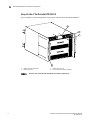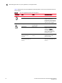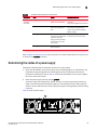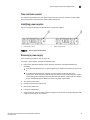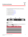
1
5 53-1002177-05 10 May 2012 Brocade DCX 8510-4 Backbone Hardware Reference Manual ® Copyright © 2011-2012 Brocade Communications Systems, Inc. All Rights Reserved. Brocade, Brocade Assurance, the B-wing symbol, BigIron, DCX, Fabric OS, FastIron, MLX, NetIron, SAN Health, ServerIron, TurboIron, VCS, and VDX are registered trademarks, and AnyIO, Brocade One, CloudPlex, Effortless Networking, ICX, NET Health, OpenScript, and The Effortless Network are trademarks of Brocade Communications Systems, Inc., in the United States and/or in other countries. Other brands, products, or service names mentioned may be trademarks of their respective owners. Notice: This document is for informational purposes only and does not set forth any warranty, expressed or implied, concerning any equipment, equipment feature, or service offered or to be offered by Brocade. Brocade reserves the right to make changes to this document at any time, without notice, and assumes no responsibility for its use. This informational document describes features that may not be currently available. Contact a Brocade sales office for information on feature and product availability. Export of technical data contained in this document may require an export license from the United States government. The authors and Brocade Communications Systems, Inc. shall have no liability or responsibility to any person or entity with respect to any loss, cost, liability, or damages arising from the information contained in this book or the computer programs that accompany it. The product described by this document may contain “open source” software covered by the GNU General Public License or other open source license agreements. To find out which open source software is included in Brocade products, view the licensing terms applicable to the open source software, and obtain a copy of the programming source code, please visit http://www.brocade.com/support/oscd. Brocade Communications Systems, Incorporated Corporate and Latin American Headquarters Brocade Communications Systems, Inc. 130 Holger Way San Jose, CA 95134 Tel: 1-408-333-8000 Fax: 1-408-333-8101 E-mail: [email protected] Asia-Pacific Headquarters Brocade Communications Systems China HK, Ltd. No. 1 Guanghua Road Chao Yang District Units 2718 and 2818 Beijing 100020, China Tel: +8610 6588 8888 Fax: +8610 6588 9999 E-mail: [email protected] European Headquarters Brocade Communications Switzerland Sàrl Centre Swissair Tour B - 4ème étage 29, Route de l'Aéroport Case Postale 105 CH-1215 Genève 15 Switzerland Tel: +41 22 799 5640 Fax: +41 22 799 5641 E-mail: [email protected] Asia-Pacific Headquarters Brocade Communications Systems Co., Ltd. (Shenzhen WFOE) Citic Plaza No. 233 Tian He Road North Unit 1308 – 13th Floor Guangzhou, China Tel: +8620 3891 2000 Fax: +8620 3891 2111 E-mail: [email protected] Document History Title Publication number Summary of changes Date Brocade DCX 8510-4 Backbone Hardware Reference Manual 53-1002177-01 New document. April 2011 Title Publication number Summary of changes Date Brocade DCX 8510-4 Backbone Hardware Reference Manual 53-1002177-02 Updated filler panel graphics, CP replacement procedures to 7.0, data transmission range information, and rack kit measurement. June 2011 Brocade DCX 8510-4 Backbone Hardware Reference Manual 53-1002177-03 Updated power supply requirements data, power supply replacement information, ISL trunking totals, inter-chassis link information, and CP blade slot numbering. July 2011 Brocade DCX 8510-4 Backbone Hardware Reference Manual 53-1002177-04 Added new blades, FC8-32E, FC848E and enhanced ICL capability. December 2011 Brocade DCX 8510-4 Backbone Hardware Reference Manual 53-1002177-05 Added Preparing for WWN card replacement section. Corrected CR16-4 core blade power draw. May 2012 Brocade DCX 8510-4 Backbone Hardware Reference Manual 53-1002177-05 iii iv Brocade DCX 8510-4 Backbone Hardware Reference Manual 53-1002177-05 Contents About This Document In this chapter . . . . . . . . . . . . . . . . . . . . . . . . . . . . . . . . . . . . . . . . . . . xv How this document is organized . . . . . . . . . . . . . . . . . . . . . . . . . . . . xv Supported hardware and software . . . . . . . . . . . . . . . . . . . . . . . . . . xvi What’s new in this document . . . . . . . . . . . . . . . . . . . . . . . . . . . . . . . xvi Document conventions . . . . . . . . . . . . . . . . . . . . . . . . . . . . . . . . . . . . xvi Text formatting . . . . . . . . . . . . . . . . . . . . . . . . . . . . . . . . . . . . . . . xvi Command syntax conventions . . . . . . . . . . . . . . . . . . . . . . . . . xvii Command examples . . . . . . . . . . . . . . . . . . . . . . . . . . . . . . . . . xvii Notes, cautions, and warnings . . . . . . . . . . . . . . . . . . . . . . . . . xvii Notice to the reader . . . . . . . . . . . . . . . . . . . . . . . . . . . . . . . . . . . . . xviii Additional information. . . . . . . . . . . . . . . . . . . . . . . . . . . . . . . . . . . . xviii Brocade resources . . . . . . . . . . . . . . . . . . . . . . . . . . . . . . . . . . . xviii Other industry resources . . . . . . . . . . . . . . . . . . . . . . . . . . . . . . . xix Getting technical help . . . . . . . . . . . . . . . . . . . . . . . . . . . . . . . . . . . . . xix Document feedback . . . . . . . . . . . . . . . . . . . . . . . . . . . . . . . . . . . . . . .xx Chapter 1 Brocade DCX 8510-4 Backbone Overview In this chapter . . . . . . . . . . . . . . . . . . . . . . . . . . . . . . . . . . . . . . . . . . . . 1 Brocade DCX 8510-4 features . . . . . . . . . . . . . . . . . . . . . . . . . . . . . . . 1 Brocade DCX 8510-4 hardware components . . . . . . . . . . . . . . . . . . . 2 Port side of the Brocade DCX 8510-4 . . . . . . . . . . . . . . . . . . . . . 4 Nonport side of the Brocade DCX 8510-4 . . . . . . . . . . . . . . . . . . 6 Brocade DCX 8510-4 blades . . . . . . . . . . . . . . . . . . . . . . . . . . . . . . . . 7 High availability . . . . . . . . . . . . . . . . . . . . . . . . . . . . . . . . . . . . . . . . . . . 8 Reliability . . . . . . . . . . . . . . . . . . . . . . . . . . . . . . . . . . . . . . . . . . . . . . . . 8 Serviceability . . . . . . . . . . . . . . . . . . . . . . . . . . . . . . . . . . . . . . . . . . . . . 9 Software features . . . . . . . . . . . . . . . . . . . . . . . . . . . . . . . . . . . . . . . . . 9 Security . . . . . . . . . . . . . . . . . . . . . . . . . . . . . . . . . . . . . . . . . . . . . . . . 10 Network manageability . . . . . . . . . . . . . . . . . . . . . . . . . . . . . . . . . . . . 11 Chapter 2 Installation of the Brocade DCX 8510-4 In this chapter . . . . . . . . . . . . . . . . . . . . . . . . . . . . . . . . . . . . . . . . . . . 13 Time and items required. . . . . . . . . . . . . . . . . . . . . . . . . . . . . . . . . . . 13 Brocade DCX 8510-4 Backbone Hardware Reference Manual 53-1002177-05 v Preparing for Brocade DCX 8510-4 installation . . . . . . . . . . . . . . . . 14 Unpacking and installing the Brocade DCX 8510-4 . . . . . . . . . . . . . 16 Items included with the Brocade DCX 8510-4 . . . . . . . . . . . . . . . . . 17 Providing power to the Brocade DCX 8510-4 . . . . . . . . . . . . . . . . . . 18 Port numbering . . . . . . . . . . . . . . . . . . . . . . . . . . . . . . . . . . . . . . . . . . 18 Chassis slots . . . . . . . . . . . . . . . . . . . . . . . . . . . . . . . . . . . . . . . . . . . . 19 Cable management. . . . . . . . . . . . . . . . . . . . . . . . . . . . . . . . . . . . . . . 19 High density cabling. . . . . . . . . . . . . . . . . . . . . . . . . . . . . . . . . . . 20 Installing inter-chassis link (QSFP) cables (optional). . . . . . . . . 21 Chapter 3 Logging In and Configuring the Brocade DCX 8510-4 In this chapter . . . . . . . . . . . . . . . . . . . . . . . . . . . . . . . . . . . . . . . . . . . 23 Configuring the Brocade DCX 8510-4 . . . . . . . . . . . . . . . . . . . . . . . . 23 Establishing a serial connection to the Brocade DCX 8510-4 . . . . . 24 Logging in to the serial console port . . . . . . . . . . . . . . . . . . . . . . . . . 25 Configuring the IP addresses . . . . . . . . . . . . . . . . . . . . . . . . . . . . . . . 26 Logging off the serial console port and disconnecting the serial cable . . . . . . . . . . . . . . . . . . . . . . . . . . . . . . . . . . . . . . . . . . . . . 27 Establishing an Ethernet connection to the Brocade DCX 8510-4 . . . . . . . . . . . . . . . . . . . . . . . . . . . . . . . . . . . . . 27 Customizing a switch name . . . . . . . . . . . . . . . . . . . . . . . . . . . . . . . . 28 Customizing a chassis name . . . . . . . . . . . . . . . . . . . . . . . . . . . . . . . 28 Setting the domain ID . . . . . . . . . . . . . . . . . . . . . . . . . . . . . . . . . . . . . 29 Setting the date and time. . . . . . . . . . . . . . . . . . . . . . . . . . . . . . . . . . 29 Setting the date . . . . . . . . . . . . . . . . . . . . . . . . . . . . . . . . . . . . . . 29 Setting the time zone. . . . . . . . . . . . . . . . . . . . . . . . . . . . . . . . . . 30 Synchronizing local time . . . . . . . . . . . . . . . . . . . . . . . . . . . . . . . 31 Verifying the PID mode . . . . . . . . . . . . . . . . . . . . . . . . . . . . . . . . . . . . 31 Determining installed software licenses . . . . . . . . . . . . . . . . . . . . . . 32 Installing transceivers and attaching cables. . . . . . . . . . . . . . . . . . . 32 Installing SFP+ and mSFP transceivers and cables . . . . . . . . . 32 Installing QSFP transceivers and cables . . . . . . . . . . . . . . . . . . 33 Managing cables . . . . . . . . . . . . . . . . . . . . . . . . . . . . . . . . . . . . . . . . . 35 Verifying correct operation and backing up the configuration . . . . . 36 Powering off the Brocade DCX 8510-4 . . . . . . . . . . . . . . . . . . . . . . . 36 Chapter 4 Monitoring System Components In this chapter . . . . . . . . . . . . . . . . . . . . . . . . . . . . . . . . . . . . . . . . . . . 39 Monitoring overview . . . . . . . . . . . . . . . . . . . . . . . . . . . . . . . . . . . . . . 39 vi Brocade DCX 8510-4 Backbone Hardware Reference Manual 53-1002177-05 Determining the status of a port, application, or encryption blade . . . . . . . . . . . . . . . . . . . . . . . . . . . . . . . . . . . . . . . . . 44 Blade illustrations . . . . . . . . . . . . . . . . . . . . . . . . . . . . . . . . . . . .44 Determining the status of a control processor blade (CP8) . . . . . . . 50 Determining the status of a core switch blade (CR16-4) . . . . . . . . . 51 Determining the status of a power supply. . . . . . . . . . . . . . . . . . . . . 53 Determining the status of a blower assembly. . . . . . . . . . . . . . . . . . 54 Determining the status of a WWN card . . . . . . . . . . . . . . . . . . . . . . . 55 Chapter 5 Removal and Replacement Procedures In this chapter . . . . . . . . . . . . . . . . . . . . . . . . . . . . . . . . . . . . . . . . . . . 59 Introduction . . . . . . . . . . . . . . . . . . . . . . . . . . . . . . . . . . . . . . . . . . . . . 59 ESD precautions . . . . . . . . . . . . . . . . . . . . . . . . . . . . . . . . . . . . . . . . . 59 Chassis door removal and replacement . . . . . . . . . . . . . . . . . . . . . . 60 Time and items required . . . . . . . . . . . . . . . . . . . . . . . . . . . . . . . 60 Removing a chassis door . . . . . . . . . . . . . . . . . . . . . . . . . . . . . . 60 Replacing a chassis door. . . . . . . . . . . . . . . . . . . . . . . . . . . . . . . 60 Vertical cable management fingers removal and replacement. . . . 61 Time and items required . . . . . . . . . . . . . . . . . . . . . . . . . . . . . . . 61 Removing a cable management finger assembly . . . . . . . . . . . 61 Replacing a cable management finger assembly . . . . . . . . . . . 62 Port, application, and encryption blade removal and replacement . . . . . . . . . . . . . . . . . . . . . . . . . . . . . . . . . . . . . . . . . . . . 62 Time and items required . . . . . . . . . . . . . . . . . . . . . . . . . . . . . . . 62 Removing a blade . . . . . . . . . . . . . . . . . . . . . . . . . . . . . . . . . . . . 63 Replacing a blade . . . . . . . . . . . . . . . . . . . . . . . . . . . . . . . . . . . .64 Blade filler panel removal and replacement . . . . . . . . . . . . . . . . . . . 65 Removing a filler panel . . . . . . . . . . . . . . . . . . . . . . . . . . . . . . . . 65 Replacing a filler panel . . . . . . . . . . . . . . . . . . . . . . . . . . . . . . . . 66 Control processor blade (CP8) removal and replacement . . . . . . . . 66 Time and items required . . . . . . . . . . . . . . . . . . . . . . . . . . . . . . . 67 Faulty CP blade indicators. . . . . . . . . . . . . . . . . . . . . . . . . . . . . . 67 Recording critical Brocade DCX 8510-4 information. . . . . . . . . 68 Removing a control processor blade (CP8) . . . . . . . . . . . . . . . . 69 Replacing a control processor blade (CP8) . . . . . . . . . . . . . . . . 70 Verifying operation of the new CP blade. . . . . . . . . . . . . . . . . . . 71 Completing the replacement. . . . . . . . . . . . . . . . . . . . . . . . . . . . 75 Core switch blade (CR16-4) removal and replacement . . . . . . . . . . 76 Time and items required . . . . . . . . . . . . . . . . . . . . . . . . . . . . . . . 76 Faulty core switch blade indicators . . . . . . . . . . . . . . . . . . . . . . 76 Removing a core switch blade (CR16-4) . . . . . . . . . . . . . . . . . . 77 Replacing a core switch blade (CR16-4) . . . . . . . . . . . . . . . . . . 78 Brocade DCX 8510-4 Backbone Hardware Reference Manual 53-1002177-05 vii Power supply removal and replacement . . . . . . . . . . . . . . . . . . . . . . 78 Time and items required . . . . . . . . . . . . . . . . . . . . . . . . . . . . . . . 79 Identifying power supplies. . . . . . . . . . . . . . . . . . . . . . . . . . . . . . 79 Removing a power supply . . . . . . . . . . . . . . . . . . . . . . . . . . . . . . 79 Replacing a power supply . . . . . . . . . . . . . . . . . . . . . . . . . . . . . . 80 Blower assembly removal and replacement . . . . . . . . . . . . . . . . . . . 80 Time and items required . . . . . . . . . . . . . . . . . . . . . . . . . . . . . . . 81 Removing a blower assembly . . . . . . . . . . . . . . . . . . . . . . . . . . . 81 Replacing a blower assembly . . . . . . . . . . . . . . . . . . . . . . . . . . . 82 WWN card removal and replacement . . . . . . . . . . . . . . . . . . . . . . . . 82 Time and items required . . . . . . . . . . . . . . . . . . . . . . . . . . . . . . . 83 Verifying the need for replacement . . . . . . . . . . . . . . . . . . . . . . 83 Preparing for the WWN card replacement . . . . . . . . . . . . . . . . . 83 Removing the WWN bezel (logo plate) and WWN card . . . . . . . 83 Replacing the WWN card and WWN bezel (logo plate) . . . . . . . 85 Transceiver removal and replacement . . . . . . . . . . . . . . . . . . . . . . . 85 Time and items required . . . . . . . . . . . . . . . . . . . . . . . . . . . . . . . 85 Removing an SFP+ transceiver . . . . . . . . . . . . . . . . . . . . . . . . . . 86 Replacing an SFP+ transceiver . . . . . . . . . . . . . . . . . . . . . . . . . . 87 Removing and replacing an mSFP optical transceiver . . . . . . . 87 Inter-chassis link (QSFP) cable removal and replacement. . . . . . . . 88 Time and items required . . . . . . . . . . . . . . . . . . . . . . . . . . . . . . . 90 Removing an ICL cable . . . . . . . . . . . . . . . . . . . . . . . . . . . . . . . . 90 Replacing an ICL cable . . . . . . . . . . . . . . . . . . . . . . . . . . . . . . . . 90 Possible ICL configurations . . . . . . . . . . . . . . . . . . . . . . . . . . . . . 91 Brocade DCX 8510-4 chassis removal and replacement. . . . . . . . . 94 Time and items required . . . . . . . . . . . . . . . . . . . . . . . . . . . . . . . 95 Faulty Brocade DCX 8510-4 chassis indicators. . . . . . . . . . . . . 95 Recording critical Brocade DCX 8510-4 and SAN information . . . . . . . . . . . . . . . . . . . . . . . . . . . . . . . . . . . . . . 96 Disconnecting from the network and fabric . . . . . . . . . . . . . . . . 99 Removing components from the chassis . . . . . . . . . . . . . . . . .100 Installing the replacement chassis. . . . . . . . . . . . . . . . . . . . . .100 Installing components into the new chassis . . . . . . . . . . . . . .101 Downloading the configuration . . . . . . . . . . . . . . . . . . . . . . . . .102 Verifying correct operation of the system. . . . . . . . . . . . . . . . .103 Reconnecting the system to the network and fabric . . . . . . . .104 Verifying correct configuration of the fabric . . . . . . . . . . . . . . .105 Cable routing table. . . . . . . . . . . . . . . . . . . . . . . . . . . . . . . . . . .106 Appendix A Specifications In this appendix . . . . . . . . . . . . . . . . . . . . . . . . . . . . . . . . . . . . . . . . .109 General specifications . . . . . . . . . . . . . . . . . . . . . . . . . . . . . . . . . . .109 System architecture . . . . . . . . . . . . . . . . . . . . . . . . . . . . . . . . . . . . .110 System size and weight . . . . . . . . . . . . . . . . . . . . . . . . . . . . . . . . . .111 System blade and FRU weights . . . . . . . . . . . . . . . . . . . . . . . . . . . .112 Facility requirements . . . . . . . . . . . . . . . . . . . . . . . . . . . . . . . . . . . .113 viii Brocade DCX 8510-4 Backbone Hardware Reference Manual 53-1002177-05 Environmental requirements . . . . . . . . . . . . . . . . . . . . . . . . . . . . . .113 Fibre Channel port specifications . . . . . . . . . . . . . . . . . . . . . . . . . .114 Power specifications . . . . . . . . . . . . . . . . . . . . . . . . . . . . . . . . . . . . .114 Power cords . . . . . . . . . . . . . . . . . . . . . . . . . . . . . . . . . . . . . . . . . . . .116 Power cord notice. . . . . . . . . . . . . . . . . . . . . . . . . . . . . . . . . . . .119 Power cord notice (Japan DENAN) . . . . . . . . . . . . . . . . . . . . . .119 Data transmission ranges . . . . . . . . . . . . . . . . . . . . . . . . . . . . . . . .119 Qualified cables for the FC8-64 port blade . . . . . . . . . . . . . . . . . . .120 Safety notices . . . . . . . . . . . . . . . . . . . . . . . . . . . . . . . . . . . . . . . . . .121 Regulatory compliance . . . . . . . . . . . . . . . . . . . . . . . . . . . . . . . . . . .121 FCC warning (US only) . . . . . . . . . . . . . . . . . . . . . . . . . . . . . . . .122 KCC statement (Republic of Korea) . . . . . . . . . . . . . . . . . . . . .122 VCCI statement (Japan) . . . . . . . . . . . . . . . . . . . . . . . . . . . . . . .122 BSMI statement (Taiwan) . . . . . . . . . . . . . . . . . . . . . . . . . . . . .122 CE statement . . . . . . . . . . . . . . . . . . . . . . . . . . . . . . . . . . . . . . .123 Canadian requirements. . . . . . . . . . . . . . . . . . . . . . . . . . . . . . .123 German statement. . . . . . . . . . . . . . . . . . . . . . . . . . . . . . . . . . .123 Laser compliance. . . . . . . . . . . . . . . . . . . . . . . . . . . . . . . . . . . .123 Regulatory compliance standards . . . . . . . . . . . . . . . . . . . . . .123 Environmental regulation compliance . . . . . . . . . . . . . . . . . . . . . . .124 China RoHS . . . . . . . . . . . . . . . . . . . . . . . . . . . . . . . . . . . . . . . .124 Appendix B Application and Encryption Blades In this appendix . . . . . . . . . . . . . . . . . . . . . . . . . . . . . . . . . . . . . . . . .129 Introduction . . . . . . . . . . . . . . . . . . . . . . . . . . . . . . . . . . . . . . . . . . . .129 FS8-18 blade . . . . . . . . . . . . . . . . . . . . . . . . . . . . . . . . . . . . . . . . . . .129 FX8-24 blade . . . . . . . . . . . . . . . . . . . . . . . . . . . . . . . . . . . . . . . . . . .130 Appendix C Diagnostics and Troubleshooting In this appendix . . . . . . . . . . . . . . . . . . . . . . . . . . . . . . . . . . . . . . . . .133 Introduction . . . . . . . . . . . . . . . . . . . . . . . . . . . . . . . . . . . . . . . . . . . .133 Obtaining chassis and component status . . . . . . . . . . . . . . . . . . . .134 Interpreting POST and boot results . . . . . . . . . . . . . . . . . . . . . . . . .134 POST . . . . . . . . . . . . . . . . . . . . . . . . . . . . . . . . . . . . . . . . . . . . . .134 Boot. . . . . . . . . . . . . . . . . . . . . . . . . . . . . . . . . . . . . . . . . . . . . . .135 Diagnostics . . . . . . . . . . . . . . . . . . . . . . . . . . . . . . . . . . . . . . . . . . . .135 Troubleshooting. . . . . . . . . . . . . . . . . . . . . . . . . . . . . . . . . . . . . . . . .136 Appendix D Port Numbering Template Index Brocade DCX 8510-4 Backbone Hardware Reference Manual 53-1002177-05 ix x Brocade DCX 8510-4 Backbone Hardware Reference Manual 53-1002177-05 Figures Figure 1 Port side of the Brocade DCX 8510-4 (sample configuration) . . . . . . . . . . . . . . . 4 Figure 2 Port side of the Brocade DCX 8510-4 with the port side exhaust kit installed (sample configuration) . . . . . . . . . . . . . . . . . . . . . . . . . . . . . . . . . . . . . . . . . . . . . . . 5 Figure 3 Nonport side of the Brocade DCX 8510-4 (sample configuration) . . . . . . . . . . . . 6 Figure 4 Cable design for the mSFP patch cables for the FC8-64 high density port blade . . . . . . . . . . . . . . . . . . . . . . . . . . . . . . . . . . . . . . . . . . . . . . . . . . . . . . . . 21 Figure 5 Configuration tasks. . . . . . . . . . . . . . . . . . . . . . . . . . . . . . . . . . . . . . . . . . . . . . . . . 24 Figure 6 FC8-64 port blade. . . . . . . . . . . . . . . . . . . . . . . . . . . . . . . . . . . . . . . . . . . . . . . . . . 44 Figure 7 FC8-32E port blade . . . . . . . . . . . . . . . . . . . . . . . . . . . . . . . . . . . . . . . . . . . . . . . . 45 Figure 8 FC8-48E port blade . . . . . . . . . . . . . . . . . . . . . . . . . . . . . . . . . . . . . . . . . . . . . . . . 45 Figure 9 FC16-32 port blade . . . . . . . . . . . . . . . . . . . . . . . . . . . . . . . . . . . . . . . . . . . . . . . . 46 Figure 10 FC16-48 port blade . . . . . . . . . . . . . . . . . . . . . . . . . . . . . . . . . . . . . . . . . . . . . . . . 46 Figure 11 FS8-18 encryption blade . . . . . . . . . . . . . . . . . . . . . . . . . . . . . . . . . . . . . . . . . . . . 47 Figure 12 FX8-24 extension blade . . . . . . . . . . . . . . . . . . . . . . . . . . . . . . . . . . . . . . . . . . . . . 47 Figure 13 Control processor blade (CP8). . . . . . . . . . . . . . . . . . . . . . . . . . . . . . . . . . . . . . . . 50 Figure 14 Core switch blade (CR16-4) . . . . . . . . . . . . . . . . . . . . . . . . . . . . . . . . . . . . . . . . . . 52 Figure 15 Power supply . . . . . . . . . . . . . . . . . . . . . . . . . . . . . . . . . . . . . . . . . . . . . . . . . . . . . . 54 Figure 16 Blower assembly . . . . . . . . . . . . . . . . . . . . . . . . . . . . . . . . . . . . . . . . . . . . . . . . . . . 55 Figure 17 WWN bezel (logo plate) for DCX 8510-4 . . . . . . . . . . . . . . . . . . . . . . . . . . . . . . . . 57 Figure 18 Removal and replacement of the chassis door . . . . . . . . . . . . . . . . . . . . . . . . . . 60 Figure 19 Removal and replacement of the vertical cable management finger assemblies . . . . . . . . . . . . . . . . . . . . . . . . . . . . . . . . . . . . . . . . . . . . . . . . . . 62 Figure 20 Removal and replacement of the port, application, or encryption blades (FC16-48 port blade shown) . . . . . . . . . . . . . . . . . . . . . . . . . . . . . . . . . . . . . . . . . 64 Figure 21 Removal and replacement of the blade filler panel . . . . . . . . . . . . . . . . . . . . . . . 66 Figure 22 Removal and replacement of the control processor blade (CP8) . . . . . . . . . . . . 70 Figure 23 Removal and replacement of the core switch blade (CR16-4) . . . . . . . . . . . . . . 78 Figure 24 Power supply identification . . . . . . . . . . . . . . . . . . . . . . . . . . . . . . . . . . . . . . . . . . 79 Figure 25 Removal and replacement of the power supply . . . . . . . . . . . . . . . . . . . . . . . . . . 80 Figure 26 Removal and replacement of the blower assembly . . . . . . . . . . . . . . . . . . . . . . . 82 Figure 27 Removal and replacement of the WWN bezel (logo plate) and WWN card . . . . 84 Figure 28 Optical transceiver (SFP+) extraction tool. . . . . . . . . . . . . . . . . . . . . . . . . . . . . . . 86 Figure 29 Optical transceiver with bail open . . . . . . . . . . . . . . . . . . . . . . . . . . . . . . . . . . . . . 87 Figure 30 Optical mSFP transceiver . . . . . . . . . . . . . . . . . . . . . . . . . . . . . . . . . . . . . . . . . . . . 88 Figure 31 QSFP cable and transceiver. . . . . . . . . . . . . . . . . . . . . . . . . . . . . . . . . . . . . . . . . . 90 Figure 32 QSFP transceiver (bail open) . . . . . . . . . . . . . . . . . . . . . . . . . . . . . . . . . . . . . . . . . 90 Brocade DCX 8510-4 Backbone Hardware Reference Manual 53-1002177-05 xi xii Figure 33 QSFP cable connections for Brocade DCX 8510 chassis (sample configuration) . . . . . . . . . . . . . . . . . . . . . . . . . . . . . . . . . . . . . . . . . . . . . . 92 Figure 34 DCX 8510 core/edge ICL topology . . . . . . . . . . . . . . . . . . . . . . . . . . . . . . . . . . . . 93 Figure 35 DCX 8510 full mesh ICL topology . . . . . . . . . . . . . . . . . . . . . . . . . . . . . . . . . . . . . 94 Figure 36 CR16-4 core blade . . . . . . . . . . . . . . . . . . . . . . . . . . . . . . . . . . . . . . . . . . . . . . . . 139 Figure 37 FC8-64 port blade. . . . . . . . . . . . . . . . . . . . . . . . . . . . . . . . . . . . . . . . . . . . . . . . . 140 Figure 38 FC8-32E port blade . . . . . . . . . . . . . . . . . . . . . . . . . . . . . . . . . . . . . . . . . . . . . . . 140 Figure 39 FC8-48E port blade . . . . . . . . . . . . . . . . . . . . . . . . . . . . . . . . . . . . . . . . . . . . . . . 140 Figure 40 FC16-32 port blade . . . . . . . . . . . . . . . . . . . . . . . . . . . . . . . . . . . . . . . . . . . . . . . 141 Figure 41 FC16-48 port blade . . . . . . . . . . . . . . . . . . . . . . . . . . . . . . . . . . . . . . . . . . . . . . . 141 Figure 42 FS8-18 encryption blade . . . . . . . . . . . . . . . . . . . . . . . . . . . . . . . . . . . . . . . . . . . 141 Figure 43 FX8-24 extension blade . . . . . . . . . . . . . . . . . . . . . . . . . . . . . . . . . . . . . . . . . . . . 142 Brocade DCX 8510-4 Backbone Hardware Reference Manual 53-1002177-05 Tables Table 1 Blades available for the Brocade DCX 8510-4. . . . . . . . . . . . . . . . . . . . . . . . . . . . 7 Table 2 Installation tasks, time, and items required . . . . . . . . . . . . . . . . . . . . . . . . . . . . . 14 Table 3 Port and application blade LED descriptions . . . . . . . . . . . . . . . . . . . . . . . . . . . . 48 Table 4 CP blade LED descriptions . . . . . . . . . . . . . . . . . . . . . . . . . . . . . . . . . . . . . . . . . . . 50 Table 5 CR blade LED descriptions. . . . . . . . . . . . . . . . . . . . . . . . . . . . . . . . . . . . . . . . . . . 52 Table 6 Power supply LED descriptions . . . . . . . . . . . . . . . . . . . . . . . . . . . . . . . . . . . . . . . 54 Table 7 Blower assembly LED descriptions . . . . . . . . . . . . . . . . . . . . . . . . . . . . . . . . . . . . 55 Table 8 Messages that may indicate WWN card failure . . . . . . . . . . . . . . . . . . . . . . . . . . 56 Table 9 Steps for upgrading through multiple versions of Fabric OS. . . . . . . . . . . . . . . . 72 Table 10 QSFP connector port LEDs . . . . . . . . . . . . . . . . . . . . . . . . . . . . . . . . . . . . . . . . . . . 89 Table 11 Critical information checklist . . . . . . . . . . . . . . . . . . . . . . . . . . . . . . . . . . . . . . . . . 96 Table 12 Cable routing table for Brocade DCX 8510-4 (64 ports shown) . . . . . . . . . . . . 106 Table 13 General specifications . . . . . . . . . . . . . . . . . . . . . . . . . . . . . . . . . . . . . . . . . . . . . 109 Table 14 System architecture . . . . . . . . . . . . . . . . . . . . . . . . . . . . . . . . . . . . . . . . . . . . . . . 110 Table 15 System size and weight . . . . . . . . . . . . . . . . . . . . . . . . . . . . . . . . . . . . . . . . . . . . 112 Table 16 System FRU weights . . . . . . . . . . . . . . . . . . . . . . . . . . . . . . . . . . . . . . . . . . . . . . . 112 Table 17 Environmental requirements . . . . . . . . . . . . . . . . . . . . . . . . . . . . . . . . . . . . . . . . 113 Table 18 Power specifications. . . . . . . . . . . . . . . . . . . . . . . . . . . . . . . . . . . . . . . . . . . . . . . 115 Table 19 Power demands per component . . . . . . . . . . . . . . . . . . . . . . . . . . . . . . . . . . . . . 115 Table 20 Power supply requirements . . . . . . . . . . . . . . . . . . . . . . . . . . . . . . . . . . . . . . . . . 116 Table 21 Power cord types (international) . . . . . . . . . . . . . . . . . . . . . . . . . . . . . . . . . . . . . 117 Table 22 Supported optics, speeds, cables, and distances . . . . . . . . . . . . . . . . . . . . . . . 120 Table 23 Qualified cables for mSFP connections for the FC8-64 high density port blade 120 Table 24 Regulatory compliance standards . . . . . . . . . . . . . . . . . . . . . . . . . . . . . . . . . . . . 124 Table 25 Environmental status and maintenance commands . . . . . . . . . . . . . . . . . . . . . 134 Table 26 Troubleshooting the Brocade DCX 8510-4 . . . . . . . . . . . . . . . . . . . . . . . . . . . . . 136 Table 27 External port to slotShow port mapping for core blades . . . . . . . . . . . . . . . . . . 139 Brocade DCX 8510-4 Backbone Hardware Reference Manual 53-1002177-05 xiii xiv Brocade DCX 8510-4 Backbone Hardware Reference Manual 53-1002177-05 About This Document In this chapter • How this document is organized . . . . . . . . . . . . . . . . . . . . . . . . . . . . . . . . . . xv • Supported hardware and software. . . . . . . . . . . . . . . . . . . . . . . . . . . . . . . . . xvi • What’s new in this document . . . . . . . . . . . . . . . . . . . . . . . . . . . . . . . . . . . . . xvi • Document conventions . . . . . . . . . . . . . . . . . . . . . . . . . . . . . . . . . . . . . . . . . . xvi • Notice to the reader . . . . . . . . . . . . . . . . . . . . . . . . . . . . . . . . . . . . . . . . . . . xviii • Additional information . . . . . . . . . . . . . . . . . . . . . . . . . . . . . . . . . . . . . . . . . . xviii • Getting technical help . . . . . . . . . . . . . . . . . . . . . . . . . . . . . . . . . . . . . . . . . . . xix • Document feedback . . . . . . . . . . . . . . . . . . . . . . . . . . . . . . . . . . . . . . . . . . . . xx How this document is organized This document is a hardware reference manual written for system administrators and technicians experienced with networking, Fibre Channel, and SAN technologies to help them install, set up, configure, operate, maintain, and troubleshoot the Brocade DCX 8510-4 Backbone (“Brocade DCX 8510-4”). This document presents information on setting up and operating the Brocade DCX 8510-4. It is organized in a loosely chronological order, beginning with an overview of the Brocade DCX 8510-4 and ending with removal and replacement procedures of field-replaceable units (FRUs). The document contains the following sections: • Chapter 1, “Brocade DCX 8510-4 Backbone Overview,” identifies the components of the Brocade DCX 8510-4 and provides a brief description of its features. • Chapter 2, “Installation of the Brocade DCX 8510-4,” describes how to install, set up, and power on the Brocade DCX 8510-4. • Chapter 3, “Logging In and Configuring the Brocade DCX 8510-4,” provides the initial configuration information required to get the Brocade DCX 8510-4 established in a fabric. • Chapter 4, “Monitoring System Components,” provides descriptions of the LEDs and their functions, and also lists Fabric OS commands required for monitoring the Brocade DCX 8510-4. • Chapter 5, “Removal and Replacement Procedures,” describes how to remove and replace each of the FRUs in the Brocade DCX 8510-4. • Appendix A, “Specifications,” provides information on the physical characteristics, environmental requirements, and regulatory certifications for the Brocade DCX 8510-4. • Appendix B, “Application and Encryption Blades,” provides information about application blades that are optionally available for the Brocade DCX 8510-4. Brocade DCX 8510-4 Backbone Hardware Reference Manual 53-1002177-05 xv Supported hardware and software • Appendix C, “Diagnostics and Troubleshooting,” provides methods for receiving system-wide or component-level status and interpreting POST and boot activities and diagnostic tests; it also includes troubleshooting tips. • Appendix D, “Port Numbering Template,” contains templates where you can record the port numbering sequence for the port blades. Supported hardware and software This document includes information specific to the Brocade DCX 8510-4 running Brocade Fabric OS version 7.0.0 and later. What’s new in this document The following information has been added: • Corrected maximum power draw for CR16-4 core blade. Refer to “Power demands per component.” Document conventions This section describes text formatting conventions and important notice formats used in this document. Text formatting The narrative-text formatting conventions that are used in this document are as follows: bold text Identifies command names Identifies GUI elements Identifies keywords and operands Identifies text to enter at the GUI or CLI italic text Provides emphasis Identifies variables Identifies paths and Internet addresses Identifies document titles code text Identifies CLI output Identifies syntax examples For readability, command names in the narrative portions of this guide are presented in mixed lettercase: for example, switchShow. In actual examples, command lettercase is often all lowercase. Otherwise, this manual specifically notes those cases in which a command is case-sensitive. xvi Brocade DCX 8510-4 Backbone Hardware Reference Manual 53-1002177-05 Document conventions Command syntax conventions Command syntax in this manual follows these conventions: command Commands are printed in bold. --option, option Command options are printed in bold. -argument, arg Arguments. [] Optional element. variable Variables are printed in italics. In the help pages, values are underlined or enclosed in angled brackets < >. ... Repeat the previous element, for example “member[;member...]” value Fixed values following arguments are printed in plain font. For example, --show WWN | Boolean. Elements are exclusive. Example: --show -mode egress | ingress Command examples This book describes how to perform configuration tasks using the Fabric OS command line interface, but does not describe the commands in detail. For complete descriptions of all Fabric OS commands, including syntax, operand description, and sample output, refer to the Fabric OS Command Reference. Notes, cautions, and warnings The following notices and statements are used in this manual. They are listed below in order of increasing severity of potential hazards. NOTE A note provides a tip, guidance, or advice, emphasizes important information, or provides a reference to related information. ATTENTION An Attention statement indicates potential damage to hardware or data. Brocade DCX 8510-4 Backbone Hardware Reference Manual 53-1002177-05 xvii Notice to the reader CAUTION A Caution statement alerts you to situations that can be potentially hazardous to you or cause damage to hardware, firmware, software, or data. DANGER A Danger statement indicates conditions or situations that can be potentially lethal or extremely hazardous to you. Safety labels are also attached directly to products to warn of these conditions or situations. Notice to the reader This document may contain references to the trademarks of the following corporations. These trademarks are the properties of their respective companies and corporations. These references are made for informational purposes only. Corporation Referenced Trademarks and Products Microsoft Corporation Windows, Windows NT, Internet Explorer Sun Microsystems, Inc. Sun, Solaris Netscape Communications Corporation Netscape Red Hat, Inc. Red Hat, Red Hat Network, Maximum RPM, Linux Undercover Velcro Industries B.V. Velcro Additional information This section lists additional Brocade and industry-specific documentation that you might find helpful. Brocade resources To get up-to-the-minute information, go to http://my.brocade.com to register at no cost for a user ID and password. White papers, online demonstrations, and data sheets are available through the Brocade website at: http://www.brocade.com/products-solutions/products/index.page xviii Brocade DCX 8510-4 Backbone Hardware Reference Manual 53-1002177-05 Getting technical help For additional Brocade documentation, visit the Brocade website: http://www.brocade.com Release notes are available on the MyBrocade website and are also bundled with the Fabric OS firmware. Other industry resources For additional resource information, visit the Technical Committee T11 website. This website provides interface standards for high-performance and mass storage applications for Fibre Channel, storage management, and other applications: http://www.t11.org For information about the Fibre Channel industry, visit the Fibre Channel Industry Association website: http://www.fibrechannel.org Getting technical help Contact your Brocade DCX 8510-4 supplier for hardware, firmware, and software support, including product repairs and part ordering. To expedite your call, have the following information available: 1. General information • • • • • • • • • Technical Support contract number, if applicable Model name Operating system version Error numbers and messages received supportSave command output Detailed description of the problem and specific questions Description of any troubleshooting steps already performed and results Serial console and Telnet session logs syslog message logs 2. Brocade DCX 8510-4 serial number The Brocade DCX 8510-4 serial number (Switch Serial No.) and corresponding bar code are provided on the serial number label, as shown here: *FT00X0054E9* FT00X0054E9 The serial number label is located on the port side of the chassis, on the lower right side and directly above the cable management comb. Brocade DCX 8510-4 Backbone Hardware Reference Manual 53-1002177-05 xix Document feedback In addition, the chassisShow command displays the Brocade DCX 8510-4 serial number, as well as information about the port and application blades, and other field-replaceable units (FRUs). 3. License ID Use the licenseIdShow command to display the license ID. 4. World Wide Name (WWN) Use the wwn command to display the switch WWN. If you cannot use the wwn command because the switch is inoperable, you can get the WWN from the same place as the serial number, except for the Brocade DCX 8510-4. For the Brocade DCX 8510-4, access the numbers on the WWN cards by removing the Brocade logo plate at the top of the nonport side of the chassis. Document feedback Because quality is our first concern at Brocade, we have made every effort to ensure the accuracy and completeness of this document. However, if you find an error or an omission, or you think that a topic needs further development, we want to hear from you. Forward your feedback to: [email protected] Provide the title and version number and as much detail as possible about your comment, including the topic heading and page number and your suggestions for improvement. xx Brocade DCX 8510-4 Backbone Hardware Reference Manual 53-1002177-05 Chapter Brocade DCX 8510-4 Backbone Overview 1 In this chapter • Brocade DCX 8510-4 features . . . . . . . . . . . . . . . . . . . . . . . . . . . . . . . . . . . . . 1 • Brocade DCX 8510-4 hardware components . . . . . . . . . . . . . . . . . . . . . . . . . 2 • Brocade DCX 8510-4 blades . . . . . . . . . . . . . . . . . . . . . . . . . . . . . . . . . . . . . . 7 • High availability . . . . . . . . . . . . . . . . . . . . . . . . . . . . . . . . . . . . . . . . . . . . . . . . . 8 • Reliability . . . . . . . . . . . . . . . . . . . . . . . . . . . . . . . . . . . . . . . . . . . . . . . . . . . . . . 8 • Serviceability . . . . . . . . . . . . . . . . . . . . . . . . . . . . . . . . . . . . . . . . . . . . . . . . . . . 9 • Software features . . . . . . . . . . . . . . . . . . . . . . . . . . . . . . . . . . . . . . . . . . . . . . . 9 • Security. . . . . . . . . . . . . . . . . . . . . . . . . . . . . . . . . . . . . . . . . . . . . . . . . . . . . . . 10 • Network manageability . . . . . . . . . . . . . . . . . . . . . . . . . . . . . . . . . . . . . . . . . . 11 Brocade DCX 8510-4 features The Brocade DCX 8510-4 is part of Brocade's industry-leading Backbone-class product line, a highly robust class of network switching platform that combines breakthrough performance, scalability, and energy efficiency with long-term investment. Brocade 8510 Backbones are the industry’s most powerful Fibre Channel switching infrastructure, providing the most reliable, scalable, high performance foundation for private cloud storage and highly virtualized environments. They are designed to increase business agility by adapting to dynamic growth and change, providing high availability access to information, and reducing infrastructure and administrative costs. Key features of the Brocade DCX 8510-4 include: • Up to 192 16 Gbps external ports in a single chassis, enabling high density SAN configurations with reduced footprint. • Support for 2, 4, 8, and 16 Gbps auto-sensing Fibre Channel ports. Trunking technology groups up to eight ports to create high performance 128-Gbps ISL trunks between switches. • The Brocade DCX 8510-4 also supports 10 Gbps FC-type SFPs in 16 Gbps port blades only and also supports 10 GbE SFPs in the FX8-24 application blade. The two types of SFPs are not interchangeable. • The 10 Gbps ports can be configured manually on only the first eight ports of the 16 Gbps port blades. • Support for many of the application, port blade, and control processor (CP) blades supported in the Brocade 8510-4 (with the exception of the Core Switch Blade), thereby providing flexible system configurations and fewer types of new blades. Brocade DCX 8510-4 Backbone Hardware Reference Manual 53-1002177-05 1 1 Brocade DCX 8510-4 hardware components • Beginning with Fabric OS v7.0.1, up to nine chassis can be connected with the use of 4x16 Gbps quad SFP (QSFP) inter-chassis links (ICLs). Fabric OS v7.0.0 permits up to six chassis to be linked. • Support for high-performance port blades running at 2, 4, 8, 10, or 16 Gbps, enabling flexible system configuration. • Redundant and hot-swappable control processor and core switch blades, power supplies, blower assemblies, and WWN cards that enable a high availability platform and enable nondisruptive software upgrades for mission-critical SAN applications. • Universal ports that self-configure as E_Ports, F_Ports, EX_Ports and M_Ports (mirror ports). 10 Gbps ports are E_Ports only. • Diagnostic port (D_Port) functionality. • In-flight data cryptographic (encryption/decryption) and data compression capabilities through the 16 Gbps port blades. • Fibre Channel over IP (FCIP) functionality through the FX8-24 blade. Brocade DCX 8510-4 hardware components The Brocade DCX 8510-4 features a modular and scalable mechanical construction that allows a wide range of flexibility in installation, fabric design, and maintenance. The chassis can be mounted with the cables facing the front of the equipment rack or to the rear, and consists of the following: • Up to four hot-swappable port blade assemblies that can be configured in a single chassis, delivering up to 192 16 Gbps Fibre Channel ports. • Two slots for control processor blades (CP8): - A single active CP8 blade can control all 192 ports in the chassis. - The standby CP8 blade assumes control of the Brocade DCX 8510-4 if the active CP fails. • Two slots for core switch blades (CR16-4): - CR16-4 blade interconnects all port blades. - Inter-chassis link (ICL) connectors to connect to as many as nine neighboring chassis under Fabric OS v7.0.1. Six chassis can be connected under Fabric OS v7.0.0. - Both CR16-4 blades are active. • Modular, hot-swappable port blades: - 64-port, 8-Gbps blades (FC8-64) - 32-port, 8-Gbps blades (FC8-32E) - 48-port, 8-Gbps blades (FC8-48E) - 32-port, 16-Gbps blades (FC16-32) - 48-port, 16-Gbps blades (FC16-48) • Modular, hot-swappable application blades: - FX8-24: 24-port (12 FC, 10 GbE, 2 10GbE) FCIP extension blade enabling long distance communication over existing IP infrastructure. 2 Brocade DCX 8510-4 Backbone Hardware Reference Manual 53-1002177-05 Brocade DCX 8510-4 hardware components 1 • Modular, hot-swappable encryption blades: - FS8-18: 16-port, up to 4 blades per chassis, supporting in-flight data cryptographic (encryption/decryption) and data-compression capabilities. • Modular, hot-swappable field-replaceable units (FRUs): - Two blower assemblies. - Two power supplies (100-240 VAC auto-sensing). - At 110 VAC (nominal): A minimum of two power supplies is required, regardless of the number of port or application blades. This configuration does not support high availability. 220 VAC (nominal) is recommended for efficiency. A second power supply is required to support high availability. Redundant AC primary power connections ensure high availability. Each power supply has its own connector, so the number of primary power connections is two for optimum efficiency and redundancy. Two WWN cards. Blades use small form-factor pluggable (SFP+ and mSFP) optical transceivers. SFP+ and mSFP transceivers support speeds of 2, 4, 8, 10, or 16 Gbps. NOTE The 8-Gbps SFP+s and mSFPs auto-negotiate at 2, 4, and 8 Gbps. The 16-Gbps SFP+s auto-negotiate at 4, 8, and 16 Gbps. The 10 Gbps speeds must be manually set and require special 10 Gbps SFP+ transceivers. - QSFP-based inter-chassis link (ICL) cabling running at 64 Gbps (four 16 Gbps clustered in a single quad connector and cable). • Blades that are serviced from the port side of the Brocade DCX 8510-4. Blowers, power supplies, and power cables that are serviced from the nonport side. • World Wide Name (WWN) cards on the nonport side, with WWN status LEDs located under the bezel. • Two vertical cable management finger assemblies and a redesigned chassis door for improved cable management. Brocade DCX 8510-4 Backbone Hardware Reference Manual 53-1002177-05 3 1 Brocade DCX 8510-4 hardware components Port side of the Brocade DCX 8510-4 NOTE Airflow in the Brocade DCX 8510-4 is from the nonport side to the left side and port side of the chassis (viewed from the port side) and out the exhaust vents. If you use the Port Side Exhaust Kit, the air vents are all on the port side of the chassis (see Figure 2). Figure 1 displays a sample configuration of the port side of the Brocade DCX 8510-4. 1 2 3 4 1 2 Port blade (FC16-32) Core switch blade (CR16-4) FIGURE 1 4 3 4 Control processor blade (CP8) Exhaust vent Port side of the Brocade DCX 8510-4 (sample configuration) Brocade DCX 8510-4 Backbone Hardware Reference Manual 53-1002177-05 Brocade DCX 8510-4 hardware components FIGURE 2 1 Port side of the Brocade DCX 8510-4 with the port side exhaust kit installed (sample configuration) Brocade DCX 8510-4 Backbone Hardware Reference Manual 53-1002177-05 5 1 Brocade DCX 8510-4 hardware components Nonport side of the Brocade DCX 8510-4 Figure 3 displays a sample configuration of the nonport side view of the Brocade DCX 8510-4. 1 2 3 4 1 2 WWN card bezel (logo plate) Power supply (2x) FIGURE 3 6 3 4 Blower assembly (2x) Label with serial number and WWN Nonport side of the Brocade DCX 8510-4 (sample configuration) Brocade DCX 8510-4 Backbone Hardware Reference Manual 53-1002177-05 Brocade DCX 8510-4 blades 1 Brocade DCX 8510-4 blades Table 1 summarizes the port, application, control processor, and core switch blades that are available for the Brocade DCX 8510-4. TABLE 1 Blades available for the Brocade DCX 8510-4 Description Name Function Brocade DCX 8510-4 control processor blade CP8 The CP8 blade contains the control plane for the chassis. There are two CP8 blades for redundancy. This control processor blade is compatible with the Brocade DCX 8510-8, Brocade DCX 8510-4, Brocade DCX, and Brocade DCX-4S. Brocade DCX 8510-4 core switch blade CR16-4 The CR16-4 blade contains the ASICs for switching between port blades. Every port blade connects to each core switch blade. There can be up to 192 16 Gbps (256 8 Gbps) total ports for port blades. Each core switch blade connects to 128 backplane ports. Core switch blades have additional front port connectivity to connect multiple chassis and backplane connections for the storage server blade. This core switch blade is compatible only with the Brocade DCX 8510-4. 64-port 8-Gbps port blade FC8-64 A 64-port Brocade port blade supporting 2, 4, and 8 Gbps port speeds with mSFPs. This port blade is compatible with the Brocade DCX 8510-8, Brocade DCX 8510-4, Brocade DCX, and Brocade DCX-4S. 32-port 8-Gbps port blade FC8-32E A 32-port Brocade port blade supporting 2, 4, and 8 Gbps Fibre Channel port speeds. This port blade is compatible with the Brocade DCX 8510-8 and Brocade DCX 8510-4. This blade requires Fabric OS v7.0.1 or later to run in this chassis. 48-port 8-Gbps port blade FC8-48E A 48-port Brocade port blade supporting 2, 4, and 8 Gbps Fibre Channel port speeds. This port blade is compatible with the Brocade DCX 8510-8 and Brocade DCX 8510-4. This blade requires Fabric OS v7.0.1 or later to run in this chassis. 32-port 16-Gbps port blade FC16-32 A 32-port Brocade port blade supporting 2, 4, 8, 10, and 16 Gbps Fibre Channel port speeds. The blade also supports port-based in-flight encryption/decryption and compression/decompression. This port blade is compatible with the Brocade DCX 8510-8 and Brocade DCX 8510-4. 48-port 16-Gbps port blade FC16-48 A 48-port Brocade port blade supporting 2, 4, 8, 10, and 16 Gbps Fibre Channel port speeds. The blade also supports port-based in-flight encryption/decryption and compression/decompression. This port blade is compatible with the Brocade DCX 8510-8 and Brocade DCX 8510-4. Storage encryption blade FS8-18 The FS8-18 blade enables data cryptographic (encryption/decryption) and data-compression capabilities for data-at-rest. It has 16 Fibre Channel optical SFP ports. This application blade is compatible with the Brocade DCX 8510-8, Brocade DCX 8510-4, Brocade DCX, and Brocade DCX-4S. FCIP extension blade FX8-24 The FX8-24 blade enables FCIP functionality over existing IP infrastructure. It has 12 FC ports, ten 1 GbE ports, and two 10 GbE ports available. This application blade is compatible with the Brocade DCX 8510-8, Brocade DCX 8510-4, Brocade DCX, and Brocade DCX-4S. Brocade DCX 8510-4 Backbone Hardware Reference Manual 53-1002177-05 7 1 High availability High availability The following features contribute to the Brocade DCX 8510-4 high-availability design: • • • • • • • Redundant, hot-swappable FRUs, including blades, power supplies, blowers, and WWN cards Enhanced data integrity on all data paths Fabric Shortest Path First (FSPF) rerouting around failed links Integration with Simple Network Management Protocol (SNMP) managers Automatic control processor failover Nondisruptive “hot” software code loads and activation Easy configuration, save, and restore The high-availability software architecture of the Brocade DCX 8510-4 provides a common framework for all applications that reside on the system, allowing global and local states to be maintained through any component failure. High-availability elements consist of the High Availability Manager, the heartbeat, the fault/health framework, the replicated database, initialization, and software upgrade. The High Availability Manager controls access to the standby control processor, facilitates software upgrades, prevents extraneous CP failover activity, closes and flushes streams, provides flow control and message buffering, and supports a centralized active and standby state. Reliability The Brocade DCX 8510-4 uses the following error detection and correction mechanisms to ensure reliability of data: • Error Detection and Correction over main control processor memory. • Error Detection and Correction mechanism, which checks for encoder errors and fault isolation (EDFI), such as cyclic redundancy checking (CRC), parity checking, checksum, and illegal address checking. • Power-on self-test (POST). • Dual control processors that enable hot, nondisruptive fast firmware upgrades. • One serial port and two Ethernet ports (on each control processor) for management and for service. Offline control processor diagnostics and remote diagnostics simplify troubleshooting. The standby control processor monitors diagnostics to ensure the system is operational should a failover be necessary. • Bus monitoring and control of blades and other field-replaceable units (FRUs). 8 Brocade DCX 8510-4 Backbone Hardware Reference Manual 53-1002177-05 Serviceability 1 Serviceability The Brocade DCX 8510-4 provides the following features to enhance and ensure serviceability: • Modular design with hot-swappable components. • Flash memory that stores two firmware images per control processor. • USB port on control processor blades for most tasks that formerly required an FTP/SCP server, including software and firmware upgrades. • Nonvolatile random-access memory (NVRAM), containing the OEM serial number, Brocade serial number, revision information, and part number information. • • • • • • • • • Background health-check daemon. Memory scrubber, self test, and bus ping to determine if a bus is not functioning. RASlog messages. SMI-S compliant. Hardware and software watchdog timers. Status LEDs. Predictive diagnostics analysis through Fabric Watch. SNMP (including version 3) integration with higher-layer managers. Cable management using vertical finger assemblies to accommodate the horizontal orientation of the blades. Software features The Fabric OS allows any Fibre Channel-compliant device to attach to the switches as long as it conforms to the device login, name service, and related Fibre Channel standards. Each operating environment requires that a Fibre Channel host bus adapter (HBA) be available with a standards-compliant driver for correct interface to the fabric. Fabric OS consists of a set of embedded applications running on top of an embedded Linux operating system kernel. Some of these applications include: • • • • • • • • • Name server Alias server Zone server Simple Network Management Protocol (SNMP) agent SMI-S compliant API Syslog auditing RCS (Reliable Commit Service) NTP Tasks to manage address assignment, routing, link initialization, fabric initialization, link shutdown, Brocade DCX 8510-4 shutdown, and the user interface Brocade DCX 8510-4 Backbone Hardware Reference Manual 53-1002177-05 9 1 Security Security The following list highlights some of the key security features available for the Brocade DCX 8510-4 and for other Brocade enterprise-class products running Fabric OS 7.0.1 or later. For details, contact your Brocade DCX 8510-4 supplier and refer to the Brocade White Paper, “The Growing Need for Security in Storage Area Networks.” • • • • • • • • • • • • • • • • • • • • • • • • • • • • • • • • • • 10 DH-CHAP SSHv2 (using AES, 3DES, RSA) HTTPS (using AES) SNPMv3 FC-SP Secure RPC Secure file copy (SCP) Telnet disable Telnet timeout IP filters (block listeners) Secure passwords (centralized control through RADIUS/CHAP) Multiple user accounts (MUAs). Up to 255. Role-based access controls (RBACs) Administrative domains/Virtual fabrics Boot PROM password reset Password hardening policies Up front login in Web Tools Login banner Monitoring of attempted security breaches (through audit logging) Monitoring of attempted security breaches (through Fabric Watch Security Class) Fibre Channel security policies: DCC and SCC Trusted Switch (FCS) for central security management Management access controls (SNMPv3, Telnet, FTP, serial port, front panel) Hardware-enforced zoning by WWN, domain/port ID, or both Default zoning RSCN suppression and aggregation Configurable RSCN suppression by port NTPv3 (to synchronize timestamps) Event auditing Change tracking Firmware change alerts in Fabric Manager Persistent port disable Persistent domain ID E_Port disable Brocade DCX 8510-4 Backbone Hardware Reference Manual 53-1002177-05 Network manageability 1 Network manageability The Brocade DCX 8510-4 has a single domain and is managed as a single element with the Brocade Network Advisor. The Brocade DCX 8510-4 responds to its own IP address and appears as a separate entity to the Telnet protocol and SNMP. All management interfaces, such as Telnet, Web Tools, standards-compliant SMI-S, and Management Server, support a “port N within blade M” naming scheme. The Brocade DCX 8510-4 supports SNMPv1 and SNPMv3. When SNMP devices send SNMP messages to a management console running SAN management software, the information is stored in a management information base (MIB). Fabric OS v7.0.0 and later supports the latest Fibre Alliance Fibre Channel Management (FCMGMT) and Storage Management Initiative (SMI) MIBs, which allow common information necessary for management software to provide information to a SAN administrator. Refer to the Fabric OS MIB Reference for additional MIB information. Brocade DCX 8510-4 Backbone Hardware Reference Manual 53-1002177-05 11 1 12 Network manageability Brocade DCX 8510-4 Backbone Hardware Reference Manual 53-1002177-05 Chapter 2 Installation of the Brocade DCX 8510-4 In this chapter • Time and items required . . . . . . . . . . . . . . . . . . . . . . . . . . . . . . . . . . . . . . . . . • Preparing for Brocade DCX 8510-4 installation . . . . . . . . . . . . . . . . . . . . . . • Unpacking and installing the Brocade DCX 8510-4 . . . . . . . . . . . . . . . . . . . • Items included with the Brocade DCX 8510-4. . . . . . . . . . . . . . . . . . . . . . . . • Providing power to the Brocade DCX 8510-4 . . . . . . . . . . . . . . . . . . . . . . . . • Port numbering . . . . . . . . . . . . . . . . . . . . . . . . . . . . . . . . . . . . . . . . . . . . . . . . • Chassis slots . . . . . . . . . . . . . . . . . . . . . . . . . . . . . . . . . . . . . . . . . . . . . . . . . . • Cable management . . . . . . . . . . . . . . . . . . . . . . . . . . . . . . . . . . . . . . . . . . . . . 13 14 16 17 18 18 19 19 Time and items required You can set up and install the Brocade DCX 8510-4 in the following ways: • As a standalone unit on a flat surface. • In a 19-in. Electronic Industries Association (EIA) cabinet, using a Brocade DCX 8510-4, DCX-4S Rack Mount Kit (either a 27-31 in. or 18-34 in. kit depending on rack used). • In a chassis with the Port Side Exhaust Kit (provided) in an approved rack. • In a mid-mount telecommunications (Telco) rack, using the Mid-Mount Rack Kit available from your Brocade DCX 8510-4 supplier. This chapter describes how to set up the Brocade DCX 8510-4 as a standalone unit. For rack-mount installation instructions, refer to the appropriate manual as described in the following table. Table 2 describes the main installation and setup tasks, the estimated time required for each, and the items required to complete the task based on a fully populated Brocade DCX 8510-4 (192 Fibre Channel ports using the FC16-48 port blades). Configurations with fewer ports require less time. These time estimates assume a prepared installation site and appropriate power and network connectivity. Brocade DCX 8510-4 Backbone Hardware Reference Manual 53-1002177-05 13 2 Preparing for Brocade DCX 8510-4 installation TABLE 2 Installation tasks, time, and items required Installation task Time estimate Items required Site preparation and unpacking Brocade DCX 8510-4 30 minutes 1/2-in. socket wrench (to remove pallet bolts). #2 Phillips screwdriver (for cable management comb). Pallet jack. Hydraulic lift or assisted lift, able to raise to a minimum of 140 cm (55 in.), with a minimum capacity of 113 kg (250 lb). The Brocade DCX 8510-4 weighs 68 kg (150 lb) with four FC16-48 port cards installed (192 ports). Installing rack mount kit or port side exhaust kit 30 minutes Mounting and securing Brocade DCX 8510-4 in rack 30 minutes Refer to the one or more of the following if you are mounting the Brocade DCX 8510-4 in a rack: Brocade Port Side Exhaust Kit Installation Procedure Brocade DCX 8510-4, DCX-4S Mid-Mount Rack Kit Installation Procedure or Brocade DCX 8510-4, DCX-4S Rack Kit Installation Procedure. Installing power cables and powering on the Brocade DCX 8510-4 20 minutes Power cables (provided in the Brocade DCX 8510-4 accessory kit). Establishing serial connection, logging on to Brocade DCX 8510-4, and configuring IP addresses 20 minutes Serial cable (provided in the accessory kit). Workstation computer with a serial port or terminal server port and a terminal emulator application (such as HyperTerminal). Ethernet IP addresses for the Brocade DCX 8510-4 chassis and for both control processor blades: total three addresses. Installing an Ethernet cable, opening a Telnet session, and configuring the Brocade DCX 8510-4 domain ID, date and time, and additional system parameters. Verify and back up configuration. 20 minutes Ethernet cabling (optional) for Telnet access. Refer to the Fabric OS Administrator’s Guide. Installing transceivers as needed 20 minutes (longer if using high-density port blades) SFP+, mSFP, and QSFP optical transceivers as needed. Attaching fiber-optic cables, cable ties, and cable guides 2-3 hours Fiber-optic cables, cable ties, and cable comb. Preparing for Brocade DCX 8510-4 installation NOTE Read the safety notices before installation (“Safety notices”). Read “Power specifications” to plan for meeting power supply standards before installing the chassis. Read “Managing cables” to plan for cable management. 14 Brocade DCX 8510-4 Backbone Hardware Reference Manual 53-1002177-05 Preparing for Brocade DCX 8510-4 installation 2 The following steps are required to ensure correct installation and operation. 1. Plan to install the Brocade DCX 8510-4 with the nonport side facing the air-intake aisle. The Brocade DCX 8510-4 can be installed facing either direction, if serviceability and cooling requirements are met. 2. Ensure that dedicated electrical branch circuits with the following characteristics are available: NOTE Refer to “Power specifications” on page 114 for specific requirements depending on your chassis configuration. • 200–240 VAC, 50–60 Hz ( branch circuits) - recommended for high availability and maximum blade usage when configured with 192 10 Gbps ports ( circuits highly recommendedrequired for high availability if configured with 384 10 Gbps ports) Other port totals • 110-120 VAC, 50-60 Hz (four branch circuits highly recommended) • cables for 200 - 240 VAC service; up to cables for 110 - 120 VAC service • Protected by a circuit breaker in accordance with local electrical codes • Supply circuit, line fusing, and wire size adequate to the electrical rating on the chassis nameplate • Location close to the chassis and easily accessible • Grounded outlets installed by a licensed electrician and compatible with the power cords ATTENTION To maximize fault tolerance, connect each power cord to a separate power source. 3. Plan for cable management before installing the chassis. Cables can be managed in a variety of ways, such as by routing cables below the chassis, to either side of the chassis, through cable channels on the sides of the cabinet, or by using patch panels. 4. Ensure that the following is available for configuration of the Brocade DCX 8510-4: • • • • Workstation with an installed terminal emulator, such as HyperTerminal Serial cable (provided) Three Ethernet cables (including one spare) Access to an FTP server for backing up the switch configuration or collecting supportsave output data (optional) • A Brocade USB stick for collecting supportsave output data (optional) • Transceivers (copper and optical) and compatible cables 5. Ensure that the air intake and exhaust vents have a minimum of 5.1 cm (2 in.) of airspace. 6. Ensure that the air temperature on the air intake side is less than 40°C (104°F) during operation. Brocade DCX 8510-4 Backbone Hardware Reference Manual 53-1002177-05 15 2 Unpacking and installing the Brocade DCX 8510-4 Unpacking and installing the Brocade DCX 8510-4 Use the following procedure to unpack and install your Brocade DCX 8510-4. CAUTION Use safe lifting practices when moving the product. (C015) NOTE A fully populated Brocade DCX 8510-4 (four FC16-48 port cards, 192 ports) weighs approximately 68 kg (150 lbs) and requires a hydraulic or assisted lift to install it. 1. Unpack the Brocade DCX 8510-4. a. Cut the bands that encircle the packaging. b. Remove the lid and the kits and foam from the top of the chassis. c. Lift the cardboard box off the chassis and remove the plastic bag from around the chassis. Save the packing materials for use when returning the old chassis. d. Leave the chassis on top of the plastic shipping tray if the chassis must be transported to the installation location. NOTE The Brocade DCX 8510-4 packaging does not incorporate a wood pallet and pallet brackets. The chassis sits on top of a plastic shipping tray. 2. Use a pallet jack or other assisted lift to transport the new chassis to the installation area. Doorways must be wider than 36 in. (91 cm) to accommodate the chassis. 3. Remove the Brocade DCX 8510-4 port side exhaust kit (if ordered), accessory kit, packing foam, and antistatic plastic from the chassis and set aside. 4. Remove the chassis door from the Brocade DCX 8510-4. 5. Remove the vertical cable management fingers. 6. Use a lift to raise the chassis to the correct level. If installing the chassis in a cabinet, follow the instructions provided by the rack kit manufacturer. 7. If applicable, lock the wheels of the lift. 8. Gently slide the chassis onto the final installation surface, ensuring that it remains supported during the transfer. 9. Ensure that the chassis is oriented so that the nonport side has access to intake air (cool). 10. Reinstall the vertical cable management fingers. 11. Reinstall the door. The door must be installed to meet EMI compliance. 16 Brocade DCX 8510-4 Backbone Hardware Reference Manual 53-1002177-05 Items included with the Brocade DCX 8510-4 2 Items included with the Brocade DCX 8510-4 The Brocade DCX 8510-4 ships with the following: • Brocade DCX 8510-4 chassis, populated with: - Control processor blades (CP8) - Core switch blades (CR16-4) - Port blades, application blades, and encryption blades (included based on customer specification) - Blade slot filler panels (for slots not filled by blades) Port side exhaust kit (included based on customer specification) WWN cards WWN bezel (logo plate) Power supplies Power supply filler panel (included if there is only one power supply) Blower assemblies Cable management finger assemblies Chassis door • Accessory kit containing the following items: - Brocade DCX 8510-4 Backbone QuickStart Guide - Brocade Documentation CD (contains documents related to the Brocade DCX 8510-4) - ESD grounding strap - USB device - RS-232 serial cable. The RS-232 cable has an adapter at one end that can be removed to provide an RJ45-style connector. • Brocade DCX 8510-4, DCX-4S rack mount kit with instructions Order the Brocade-branded optical transceivers (SFP+, mSFP, and QSFP). The Brocade DCX 8510-4 supports SWL, LWL, and ELWL transceivers. The mSFPs and QSFPs are SWL transceivers only. NOTE For information about the SFP+, mSFP, and QSFP transceivers that are qualified for the Brocade DCX 8510-4, go to http://www.brocade.com/downloads/documents/matrices/Brocade_Compatibility_Matrix.pdf. Brocade DCX 8510-4 Backbone Hardware Reference Manual 53-1002177-05 17 2 Providing power to the Brocade DCX 8510-4 Providing power to the Brocade DCX 8510-4 Complete the following steps to provide power to the chassis. DANGER Use the supplied power cords. Ensure the facility power receptacle is the correct type, supplies the required voltage, and is properly grounded. (D004) 1. Connect the two AC power cords to the two power supplies. 2. Connect the power cords to a power source with voltage of 200 to 240 VAC, 47 to 63 Hz or optionally to a power source with voltage of 110 to 120 VAC, 47 to 63 Hz. If using any application blades in the chassis, the 200 to 240 VAC option is necessary in order to achieve power supply redundancy. ATTENTION Use of the high-voltage line (200 to 240 VAC) is highly recommended because of better power-conversion efficiency. For a fully-loaded DCX 8510-4, 200 to 240 VAC is required for high availability (ability to hot swap a failed power supply without affecting system operation). 3. Switch the AC power switches on the power supplies to I. The AC power switches light green when switched on and power is supplied. 4. The Brocade DCX 8510-4 performs a power-on self-test (POST) each time it is powered on. POST takes approximately 10 minutes and is complete when the indicator light activity displays the operational state. You can bypass POST by using the fastBoot command. You can also disable POST for successive reboots on the Brocade DCX 8510-4 using the diagDisablePost command. ATTENTION Do not connect the switch to the network until the IP addresses are configured. For information about LED patterns, see Chapter 4, “Monitoring System Components”. Port numbering The Brocade DCX 8510-4 uses the following port numbering method (Appendix D, “Port Numbering Template”). The “bottom” of the blade is the right end as you look at them installed in a Brocade DCX 8510-4 chassis. • FC8-64 port blade — Ports are numbered from 0 through 31 from right to left on the lower set of ports and 32 through 63 from right to left on the upper set of ports. Trunking groups are permitted with up to eight ports per group. Trunking groups are as follows: 0-7, 8-15, 16-23, 24-31, 32-39, 40-47, 48-55, and 56-63. • FC8-32E port blade — Ports are numbered from 0 through 15 from right to left on the lower set of ports and 16 through 31 from right to left on the upper set of ports. • FC8-48E port blade — Ports are numbered from 0 through 23 from right to left on the lower set of ports and 24 through 47 from right to left on the upper set of ports. 18 Brocade DCX 8510-4 Backbone Hardware Reference Manual 53-1002177-05 Chassis slots 2 • FC16-32 port blade — Ports are numbered from 0 through 15 from right to left on the lower set of ports and 16 through 31 from right to left on the upper set of ports. • FC16-48 port blade — Ports are numbered from 0 through 23 from right to left on the lower set of ports and 24 through 47 from right to left on the upper set of ports. • CR16-4 core blade — Inter-chassis link connectors are numbered from 0 through 7 from right to left. Each connector is actually a group of four 16 Gbps ports. • FS8-18 blade — The 16 physical Fibre Channel ports on this blade are numbered 0 through 15 from right to left. The two 10/100/1000 BaseT ports are numbered from the bottom as GE0 and GE1. • FX8-24 blade — Ports are numbered in groups. The FC ports are numbered from 0 through 11 in two horizontal rows of six ports starting from the lower right and upper right in the right-hand group of 12 ports. They are labeled FC on the front panel diagram. The two 10GbE ports are 0 and 1 and are in the lower row just to the left of the FC ports. They are labeled 10GE on the front panel diagram. The GbE ports are numbered 0 through 9 and are in both rows to the left of the FC and 10GE ports. They are labeled GE on the front panel diagram. Up to three FC trunking groups are permitted. The three groups are defined as follows: - Trunk group 0: FC ports 0, 1 Trunk group 1: FC ports 6, 7 Trunk group 2: FC ports 2, 3, 4, 5, 8, 9, 10, 11 • For more information on the FC8-64 port blade see Figure 37 on page 140. For more information on the front panel diagrams on the FX8-24 application blade, see Figure 43 on page 142. Chassis slots Chassis slots are numbered 1 through 8, from left to right when facing the port side of the Brocade DCX 8510-4. Control processor blades (CP8) can be installed only in slots 4 and 5. Core switch blades (CR16-4) can be installed only in slots 3 and 6. The rest of the slots, 1, 2, 7, and 8, can be filled with port, application, or encryption blades. Unused slots must be filled with blade filler panels to maintain adequate cooling. Cable management The cable management finger assemblies (Figure 19) are attached to the chassis to either side of the port side of the chassis and allow for simple cable management. The cable management finger assemblies can be installed without service disruption. Route the cables across in front of the blades to keep LEDs visible. Leave at least one meter of slack for each fiber-optic cable to provide room to remove and replace blades. ATTENTION The minimum radius to which a 50 micron cable can be bent under full tensile load is 5.1 cm (2 in.). For a cable under no tensile load, that minimum is 3.0 cm (1.2 in.). Brocade DCX 8510-4 Backbone Hardware Reference Manual 53-1002177-05 19 2 Cable management Cables can be organized and managed in a variety of ways, for example, using cable channels on the sides of the cabinet or patch panels to minimize cable management. Following is a list of recommendations: NOTE You should not use tie wraps with optical cables because they are easily overtightened and can damage the optic fibers. • Plan for rack space required for cable management before installing the switch. • Leave at least 1 m (3.28 ft) of slack for each port cable. This provides room to remove and replace the switch, allows for inadvertent movement of the rack, and helps prevent the cables from being bent to less than the minimum bend radius. • If you are using Brocade ISL Trunking, consider grouping cables by trunking groups. The cables used in trunking groups must meet specific requirements, as described in the Fabric OS Administrator’s Guide. • For easier maintenance, label the fiber-optic cables and record the devices to which they are connected. • Keep LEDs visible by routing port cables and other cables away from the LEDs. • Use Velcro® type straps to secure and organize fiber-optic cables. ATTENTION Do not route the cables in front of the air exhaust vent, which is located at the top of the port side of the chassis.If you are using the Port Side Exhaust Kit with your Brocade DCX 8510-4, there is also an exhaust vent at the bottom of the port side of the chassis. Use the cable management finger assemblies to keep the cables away from this exhaust vent as well. ATTENTION High density cabling The FC8-64 high density port blade cannot use the standard LC cables because the pitch between optics in the new mini-SFP (mSFP) transceiver is smaller than in standard SFPs. Patch cables and panels can be used to attach standard size cabling to the blade if necessary. Figure 4 illustrates the mSFP to SFP patch cable. Refer to “Best Practices Guide: High Density Cable Management Solutions” (available at http://www.brocade.com) for cable management guidelines for high-density port solutions, cable and patch panel part numbers. 20 Brocade DCX 8510-4 Backbone Hardware Reference Manual 53-1002177-05 2 Cable management 2 3 mSFP connector Duplex clip (black) 2 4 4 1 1 3 FIGURE 4 1.6 mm cable SFP connector Cable design for the mSFP patch cables for the FC8-64 high density port blade Note that the duplex clip on the mSFP end of the cable is black for easier recognition. See the appendix for a listing of the qualified mSFP optical cables for the FC8-64 port blade. If ISL Trunking is in use, group the cables by trunking group. The ports are color-coded to indicate which ports can be used in the same ISL Trunking group: eight ports marked with solid black ovals alternate with eight ports marked with oval outlines. Refer to Table 22 in Appendix A, “Specifications” for a listing of supported cable speeds and distances. Installing inter-chassis link (QSFP) cables (optional) Refer to “Inter-chassis link (QSFP) cable removal and replacement” for the procedure to install the QSFP cables Brocade DCX 8510-4 Backbone Hardware Reference Manual 53-1002177-05 21 2 22 Cable management Brocade DCX 8510-4 Backbone Hardware Reference Manual 53-1002177-05 Chapter 3 Logging In and Configuring the Brocade DCX 8510-4 In this chapter • Configuring the Brocade DCX 8510-4 . . . . . . . . . . . . . . . . . . . . . . . . . . . . . . • Establishing a serial connection to the Brocade DCX 8510-4 . . . . . . . . . . . • Logging in to the serial console port . . . . . . . . . . . . . . . . . . . . . . . . . . . . . . . • Configuring the IP addresses . . . . . . . . . . . . . . . . . . . . . . . . . . . . . . . . . . . . . • Logging off the serial console port and disconnecting the serial cable . . . • Establishing an Ethernet connection to the Brocade DCX 8510-4 . . . . . . . • Customizing a switch name . . . . . . . . . . . . . . . . . . . . . . . . . . . . . . . . . . . . . . • Customizing a chassis name . . . . . . . . . . . . . . . . . . . . . . . . . . . . . . . . . . . . . • Setting the domain ID . . . . . . . . . . . . . . . . . . . . . . . . . . . . . . . . . . . . . . . . . . . • Setting the date and time . . . . . . . . . . . . . . . . . . . . . . . . . . . . . . . . . . . . . . . . • Verifying the PID mode . . . . . . . . . . . . . . . . . . . . . . . . . . . . . . . . . . . . . . . . . . • Determining installed software licenses . . . . . . . . . . . . . . . . . . . . . . . . . . . . • Installing transceivers and attaching cables . . . . . . . . . . . . . . . . . . . . . . . . . • Managing cables . . . . . . . . . . . . . . . . . . . . . . . . . . . . . . . . . . . . . . . . . . . . . . . • Verifying correct operation and backing up the configuration . . . . . . . . . . . • Powering off the Brocade DCX 8510-4 . . . . . . . . . . . . . . . . . . . . . . . . . . . . . 23 24 25 26 27 27 28 28 29 29 31 32 32 35 36 36 Configuring the Brocade DCX 8510-4 The Brocade DCX 8510-4 must be configured before it is connected to the fabric, and all of the configuration commands must be entered through the active CP blade. The Brocade DCX 8510-4 configuration includes the following parameters: • • • • • IP address and subnet mask for the chassis IP addresses, host names, subnet masks, and gateway addresses for both CP blades Switch name Domain ID for the Brocade DCX 8510-4 (optional) WWN for the Brocade DCX 8510-4 The Brocade DCX 8510-4 WWN is initially set by the factory to match the license ID (which is based on the chassis serial number). The WWN can be changed but the license ID cannot be modified. Brocade DCX 8510-4 Backbone Hardware Reference Manual 53-1002177-05 23 3 Establishing a serial connection to the Brocade DCX 8510-4 The configuration information is mirrored to the standby CP blade, which allows the current configuration to remain available even if the active CP blade fails. The configuration information for the Brocade DCX 8510-4 is stored in the WWN cards and the flash memory of the CP blades. The configuration can be backed up to a workstation (uploaded) and then downloaded to the active CP blade if necessary. NOTE If the Brocade FS8-18 encryption blade is installed, refer to the Fabric OS Encryption Administrator’s Guide for the procedures to configure the encryption functions. Figure 5 illustrates the flow of the basic configuration tasks. Configuration Tasks Connect Serial Cable between Switch and Host Log In to Serial Console Port Set IP Address Log Off Serial Console Port and Disconnect Serial Cable Connect Ethernet Cable and Open Telnet Session Set Domain ID Set Date and Time Install SFPs and Attach Cables Manage Cables Verify Operation and Back Up Configuration FIGURE 5 Configuration tasks Establishing a serial connection to the Brocade DCX 8510-4 To establish a serial connection to the console port on the Brocade DCX 8510-4, complete the following steps. 24 Brocade DCX 8510-4 Backbone Hardware Reference Manual 53-1002177-05 Logging in to the serial console port 3 1. Verify that the Brocade DCX 8510-4 is powered on and that POST is complete by verifying that all power LED indicators on the port, control processor, and core switch blades display a steady green light. 2. Remove the shipping cap from the CONSOLE port on the active CP. Use the serial cable provided with the Brocade DCX 8510-4 to connect the CONSOLE port on the active CP to a computer workstation. The active CP blade is indicated by an illuminated (blue) LED. ATTENTION The CONSOLE port is intended primarily for the initial setting of the IP address and for service purposes. 3. Access the Brocade DCX 8510-4 using a terminal emulator application (such as HyperTerminal in a Windows environment or tip in a UNIX environment). 4. Disable any serial communication programs running on the workstation (such as synchronization programs). 5. Open a terminal emulator application (such as HyperTerminal on a PC, or term, tip, or kermit in a UNIX environment), and configure the application as follows: • In a Windows environment: Parameter Value Bits per second 9600 Data bits 8 Parity None Stop bits 1 Flow control None • In a UNIX environment, enter the following string at the prompt: tip /dev/ttyb -9600 If ttyb is already in use, use ttya instead and enter the following string at the prompt: tip /dev/ttya -9600 When the terminal emulator application stops reporting information, press Enter. You receive the following login prompt: CP0 Console Login: 6. Proceed to the next task. Logging in to the serial console port To log in to the Brocade DCX 8510-4 through the serial connection, follow these steps. Brocade DCX 8510-4 Backbone Hardware Reference Manual 53-1002177-05 25 3 Configuring the IP addresses 1. Log in to the Brocade DCX 8510-4 as admin. The default password is password. At the initial login, you are prompted to enter new admin and user passwords. Make sure to write down the new passwords and keep this information in a secure location. Fabric OS (swDir) swDir login: admin Password: Please change your passwords now. Use Control-C to exit or press 'Enter' key to proceed. swDir:admin> 2. (Optional) Modify passwords. To skip modifying the password, press Ctrl-C. For more information on passwords, refer to the Fabric OS Administrator’s Guide. NOTE Passwords can be 8 to 40 characters long. They must begin with an alphabetic character. They can include numeric characters, the dot (.), and the underscore (_) only. Passwords are case-sensitive, and they are not displayed when you enter them on the command line. For more information on passwords, refer to the Fabric OS Administrator’s Guide. Configuring the IP addresses The Brocade DCX 8510-4 requires three IP addresses, which are configured using the ipAddrSet command. IP addresses are required for both CP blades (CP0 and CP1) and for the chassis management IP (shown as SWITCH under the ipAddrShow command) in the Brocade DCX 8510-4. NOTE The default IP addresses and host names for the Brocade DCX 8510-4 are: – 10.77.77.75 / CP0 (the CP blade in slot 4 at the time of configuration) – 10.77.77.74 / CP1 (the CP blade in slot 5 at the time of configuration) ATTENTION Resetting an IP address while the Brocade DCX 8510-4 has active IP traffic or has management and monitoring tools running, such as DCFM, Fabric Watch, and SNMP, can cause traffic to be interrupted or stopped. Complete the following steps to set the IP addresses for the Brocade DCX 8510-4. 1. Log in to the active CP as admin using the serial cable connection. 2. Set up the Brocade DCX 8510-4 IP address by entering the ipaddrset -chassis command: swDir:admin> ipAddrSet -chassis Enter the information at the prompts. Specify the -chassis IP address. The -sw 0 IP address is not valid on this chassis. 26 Brocade DCX 8510-4 Backbone Hardware Reference Manual 53-1002177-05 Logging off the serial console port and disconnecting the serial cable 3 NOTE The addresses 10.0.0.0 through 10.0.0.255 are reserved and used internally by the Brocade DCX 8510-4. External IPs must not use these addresses. 3. Set up the CP0 IP address by entering the ipaddrset -cp 0 command: swDir:admin> ipAddrSet -cp 0 Enter the information at the prompts. 4. Set up the CP1 IP address by entering the ipaddrset -cp 1 command: swDir:admin> ipAddrSet -cp 1 Enter the information at the prompts. This is a sample IP configuration: swDir:admin> ipaddrset -chassis Ethernet IP Address [0.0.0.0]: 192.168.1.1 Ethernet Subnetmask [0.0.0.0]: 255.255.255.0 Fibre Channel IP Address [0.0.0.0]: Fibre Channel Subnetmask [0.0.0.0]: Issuing gratuitous ARP...Done. Committing configuration...Done. swDir:admin> ipaddrset -cp 0 Host Name [cp0]: Ethernet IP Address [10.77.77.75]: 192.168.1.2 Ethernet Subnetmask [0.0.0.0]: 255.255.255.0 Gateway IP Address [0.0.0.0]: 192.168.1.254 IP address is being changed...Done. Committing configuration...Done. swDir:admin> ipaddrset -cp 1 Host Name [cp1]: Ethernet IP Address [10.77.77.74]: 192.168.1.3 Ethernet Subnetmask [0.0.0.0]: 255.255.255.0 Gateway IP Address [0.0.0.0]: 192.168.1.254 IP address of remote CP is being changed...Done. Committing configuration...Done. Logging off the serial console port and disconnecting the serial cable You can use the serial port to monitor error messages through the serial connection. If the serial port is no longer required, use the logout command to log out of the serial console, remove the serial cable, and replace the plug in the serial port. Establishing an Ethernet connection to the Brocade DCX 8510-4 After using a serial connection to configure the IP addresses for the Brocade DCX 8510-4, you can connect the active CP blade to the local area network (LAN). Brocade DCX 8510-4 Backbone Hardware Reference Manual 53-1002177-05 27 3 Customizing a switch name NOTE Connecting the CP blades to a private network/VLAN is recommended. By establishing an Ethernet connection, you can complete the Brocade DCX 8510-4 configuration using either a serial session, Telnet, or management applications, such as Web Tools or Brocade Network Advisor. Perform the following steps to establish an Ethernet connection to the Brocade DCX 8510-4. 1. Remove the shipping plug from the Ethernet port on the active CP blade. 2. Insert one end of an Ethernet cable into the Ethernet port. 3. Connect the other end to an Ethernet 10/100/1000 BaseT LAN. The Brocade DCX 8510-4 can be accessed through a remote connection using the command line via Telnet or any of the management tools, such as Web Tools or Brocade Network Advisor. 4. To complete any additional Brocade DCX 8510-4 configuration procedures through a Telnet session, log in to the Brocade DCX 8510-4 by Telnet, using the admin login. The default password is password. Customizing a switch name The switch name of the Brocade DCX 8510-4 can be up to 30 characters long using Fabric OS release 6.3.0 or later; can include letters, numbers, hyphens, and underscore characters; and must begin with a letter. NOTE Changing the name causes a domain address format RSCN to be issued. 1. Type switchName followed by the new name in double quotes. swDir:admin> switchName "swModularSwitch5" Committing configuration... Done. swModularSwitch5:admin> 2. Record the new name for reference. Customizing a chassis name The chassis name of the Brocade DCX 8510-4 can be up to 15 characters long; can include letters, numbers, hyphens, and underscore characters; and must begin with a letter. 1. Enter chassisName followed by the new name in double quotes. switch:admin> chassisname "DCX8510_chassis" Committing configuration... Done. 28 Brocade DCX 8510-4 Backbone Hardware Reference Manual 53-1002177-05 Setting the domain ID 3 2. Enter chassisName by itself to show the name. switch:admin> chassisname DCX8510_chassis 3. Record the new name for reference. Setting the domain ID Each switch in the fabric must have a unique domain ID. The domain ID can be manually set through the configure command or can be automatically set. The default domain ID for the Brocade DCX 8510-4 is 1. Use the fabricShow command to view the already assigned domain IDs. 1. Enter switchDisable to disable the Brocade DCX 8510-4. 2. Enter configure. 3. Enter y at the Fabric parameters prompt: Fabric parameters (yes, y, no, n): [no] y 4. Enter a unique domain ID: Domain: (1.239) [1] 3 5. Complete the remaining prompts or press Ctrl+D to accept the settings and exit. 6. Enter switchEnable to re-enable the Brocade DCX 8510-4. Setting the date and time The date and time settings are used for logging events. Switch operation does not depend on the date and time; a switch with an incorrect date and time value still functions properly. However, because the date and time are used for logging, error detection, and troubleshooting, they should be set correctly. Setting the date To set the date, follow these steps. 1. If necessary, log on to the Brocade DCX 8510-4 by Telnet, using the admin account. The default password is password. 2. Enter the date command, using the following syntax: date "mmddHHMMyy" The values are: • mm is the month; valid values are 01 through 12. • dd is the date; valid values are 01 through 31. Brocade DCX 8510-4 Backbone Hardware Reference Manual 53-1002177-05 29 3 Setting the date and time • HH is the hour; valid values are 00 through 23. • MM is minutes; valid values are 00 through 59. • yy is the year; valid values are 00 through 99 (values greater than 69 are interpreted as 1970 through 1999, and values less than 70 are interpreted as 2000 through 2069). switch:admin> date Fri Sep 28 17:01:48 UTC 2010 switch:admin> date "0927123010" Thu Sep 27 12:30:00 UTC 2010 switch:admin> Setting the time zone You must perform the procedure on all chassis for which the time zone must be set. However, you only need to set the time zone once on each switch, because the value is written to nonvolatile memory. Use one of the two following procedures to set the time zone. The following procedure describes how to set the current time zone using timezone_fmt mode to Central Standard time. 1. Log in to the switch using the default password, which is password. 2. Enter the tsTimeZone command as follows: switch:admin> tstimezone [--interactive]/ [, timezone_fmt] Use timezone_fmt to set the time zone by Country/City or by time zone ID, such as PST. The following example shows how to change the time zone to US/Central. switch:admin> tstimezone Time Zone : US/Pacific switch:admin> tstimezone US/Central switch:admin> tstimezone Time Zone : US/Central The following procedure describes how to set the current time zone using interactive mode to Pacific Standard Time. 1. Type the tsTimeZone command as follows: switch:admin> tstimezone --interactive 2. You are prompted to select a general location. Please identify a location so that time zone rules can be set correctly. 3. Enter the appropriate number or Ctrl-D to quit. 4. At the prompt, select a country location. 5. At the prompt, enter the appropriate number to specify the time zone region or Ctrl-D to quit. 30 Brocade DCX 8510-4 Backbone Hardware Reference Manual 53-1002177-05 Verifying the PID mode 3 Synchronizing local time To synchronize the local time of the principal or primary switch with that of an external NTP server, follow these steps. 1. If necessary, log on to the switch by Telnet, using the admin account. 2. Enter the tsClockServer command: switch:admin> tsclockserver "<ntp1;ntp2>" where ntp1 is the IP address or DNS name of the first NTP server, which the switch must be able to access. The variable ntp2 is the second NTP server and is optional. The operand “<ntp1;ntp2>” is optional; by default, this value is LOCL, which uses the local clock of the principal or primary switch as the clock server. The tsClockServer command accepts multiple server addresses in either IPv4, IPv6, or DNS name formats. When multiple NTP server addresses are passed, tsClockServer sets the first obtainable address as the active NTP server. The rest will be stored as backup servers that can take over if the active NTP server fails. The principal or primary FCS switch synchronizes its time with the NTP server every 64 seconds. switch:admin> tsclockserver LOCL switch:admin> tsclockserver "132.163.135.131" switch:admin> tsclockserver 132.163.135.131 switch:admin> The following example shows how to set up more than one NTP server using a DNS name: switch:admin> tsclockserver "10.32.170.1;10.32.170.2;ntp.localdomain.net" Updating Clock Server configuration...done. Updated with the NTP servers Changes to the clock server value on the principal or primary FCS switch are propagated to all switches in the fabric Verifying the PID mode Before connecting the Brocade DCX 8510-4 to the fabric, verify that the WWN Based persistent port identifier (PID) feature on the Brocade DCX 8510-4 matches the other switches in the fabric. This parameter must be identical for all switches in the fabric and is set using the configure command as shown in the following example: switch:admin>configure Configure... Fabric parameters (yes, y, no, n): [no] y Domain: (1..239) [1] Enable a 256 Area Limit (0 = No, 1 = Zero Based Area Assignment, 2 = Port Based Area Assignment): (0..2) [0] 1 WWN Based persistent PID (yes, y, no, n): [no] yes <command output truncated> Brocade DCX 8510-4 Backbone Hardware Reference Manual 53-1002177-05 31 3 Determining installed software licenses You can check the PID setting using the configshow command as in the following example. You can use the | grep -i pid qualifier to pinpoint the PID information. switch:admin> configshow | grep -i pid fabric.ops.mode.pidFormat:1 fabric.wwnPidMode:1 The 1 indicates that the WWN Based persistent PID feature is enabled. The default value is 0 for disabled. Determining installed software licenses Depending on the vendor agreement, certain licenses are factory installed on the Brocade DCX 8510-4. To determine which licenses are enabled, use the licenseShow command. swDir:admin> licenseshow AAbbccDDeeFFeeGG: Web license Zoning license Extended Fabric license Fabric Watch license Performance Monitor license Trunking license Security license In this example, the license key is AAbbccDDeeFFeeGG. Keep a copy of the license key for reference. The 64-bit chassis ID is required to obtain and activate licenses for the Brocade DCX 8510-4. The chassis ID is available through the licenseIdShow command. The licenseShow and licenseIdShow commands must be entered on the active CP blade. Refer to the Fabric OS Administrator’s Guide for more information. Installing transceivers and attaching cables The following two sets of steps cover the installation of transceivers and cables for most SFPs and for QSFPs. Installing SFP+ and mSFP transceivers and cables Complete the following steps to install SFP-type optical transceivers. NOTE mSFP transceivers are compatible only with the FC8-64 port blade. While they will fit in other blades, this configuration is unsupported and will generate an error. 32 Brocade DCX 8510-4 Backbone Hardware Reference Manual 53-1002177-05 Installing transceivers and attaching cables 3 The ports are color-coded to indicate which can be used in the same port group for trunking (trunking port groups can be up to eight ports). The ports and cables used in trunking groups must meet specific requirements. Refer to the Fabric OS Administrator’s Guide for more information. 1. Add the optical transceivers and cables to the Fibre Channel ports. The ports are color-coded to indicate which can be used in the same port group for trunking (trunking port groups can be up to 8 ports). The ports and cables used in trunking groups must meet specific requirements. Refer to the Fabric OS Administrator’s Guide. 2. Position one of the optical transceivers so that the key is oriented correctly to the port. Insert the transceiver into the port until it is firmly seated and the latching mechanism clicks. Transceivers are keyed so that they can only be inserted with the correct orientation. If a transceiver does not slide in easily, ensure that it is correctly oriented. 3. Position a cable so that the key (the ridge on one side of the cable connector) is aligned with the slot in the transceiver. Insert the cable into the transceiver until the latching mechanism clicks. Cables are keyed so that they can be inserted in only one way. If a cable does not slide in easily, ensure that it is correctly oriented. 4. Repeat steps 1 through 3 for the remaining ports. 5. Organize the cables See “Managing Cables.” 6. Verify the Brocade DCX 8510-4 and port status using the switchShow command. 7. Verify fabric connectivity using the fabricShow command. Installing QSFP transceivers and cables Follow these steps to install the QSFPs and cables in the 16 Gbps core blades. These transceivers and cables are used to form the inter-chassis links (ICL) with neighboring DCX 8510 Backbones. The transceivers should be installed in the blades before connecting the cables. Because each QSFP contains four 16 Gbps ports, be aware that any problems with one port could affect all four ports in the quad if the QSFP has to be replaced. 1. Position one of the QSFP transceivers so that the key is oriented correctly to the port. Insert the transceiver into the port until it is firmly seated. Transceivers are keyed so that they can only be inserted with the correct orientation. If a transceiver does not slide in easily, ensure that it is correctly oriented. When the transceiver is correctly seated, the status LED will flash amber several times and then turn solid amber. 2. Remove the protective cap from the special QSFP cable and insert it into the transceiver until it is firmly seated. The cables are also keyed to fit into the transceivers correctly. When the cable is correctly seated, the status LED will change from amber to green. Repeat steps 1 and 2 for the remaining ICLs. 3. Organize the cables. See “Managing Cables.” Brocade DCX 8510-4 Backbone Hardware Reference Manual 53-1002177-05 33 3 Installing transceivers and attaching cables 4. Verify the Brocade DCX 8510-4 and connector and port status using the switchShow -qsfp command. A sample of the command output is shown below. The example is from a DCX 8510-4 with a core blade installed in slot 3. Some details for the 8510-8 will be different, but the reported information for the QSFPs will be similar. Note that the State reported for an unconnected QSFP (shown QSFP 0 and Ports 0-3 below) is No_SigDet. This is different from the State of No_Synch that is reported for regular SFPs that are unconnected. QSFP 7 (ports 3/28-3/31, Index 748-751) in the following example shows the results for a connected QSFP. switch:FID128:admin> switchshow -qsfp switchName: switch name switchType: 121.3 switchState: Online switchMode: Native switchRole: Subordinate switchDomain: 75 switchId: fffc4b switchWwn: 10:00:00:05:1e:4f:eb:00 zoning: ON (zoning name) switchBeacon: OFF FC Router: OFF Allow XISL Use: OFF LS Attributes: [FID: 128, Base Switch: No, Default Switch: Yes, Address Mode 0] Index Slot Port QSFP Address Media Speed State Proto ============================================================= 256 3 0 0 -----id 16G No_SigDet FC 257 3 1 0 -----id 16G No_SigDet FC 258 3 2 0 -----id 16G No_SigDet FC 259 3 3 0 -----id 16G No_SigDet FC 260 3 4 1 ------16G No_Module FC 261 3 5 1 ------16G No_Module FC 262 3 6 1 ------16G No_Module FC 263 3 7 1 ------16G No_Module FC 264 3 8 2 ------16G No_Module FC 265 3 9 2 ------16G No_Module FC 266 3 10 2 ------16G No_Module FC 267 3 11 2 ------16G No_Module FC 268 3 12 3 ------16G No_Module FC 269 3 13 3 ------16G No_Module FC 270 3 14 3 ------16G No_Module FC 271 3 15 3 ------16G No_Module FC 736 3 16 4 ------16G No_Module FC 737 3 17 4 ------16G No_Module FC 738 3 18 4 ------16G No_Module FC 739 3 19 4 ------16G No_Module FC 740 3 20 5 ------16G No_Module FC 741 3 21 5 ------16G No_Module FC 742 3 22 5 ------16G No_Module FC 743 3 23 5 ------16G No_Module FC 744 3 24 6 ------16G No_Module FC 745 3 25 6 ------16G No_Module FC 746 3 26 6 ------16G No_Module FC 747 3 27 6 ------16G No_Module FC 34 Brocade DCX 8510-4 Backbone Hardware Reference Manual 53-1002177-05 Managing cables 748 3 28 7 -----id 10:00:00:05:1e:39:e4:5a trunkmaster 749 3 29 7 -----id 10:00:00:05:1e:39:e4:5a trunkmaster 750 3 30 7 -----id 10:00:00:05:1e:39:e4:5a trunkmaster 751 3 31 7 -----id 10:00:00:05:1e:39:e4:5a trunkmaster 16G Online FC name (Trunk master) 16G Online FC name (Trunk master) 16G Online FC name (Trunk master) 16G Online FC name (Trunk master) 3 E-Port E-Port E-Port E-Port Managing cables Cables can be organized and managed in a variety of ways: for example, using cable channels on the port sides of the cabinet or patch panels to minimize cable management. With the horizontal orientation of the blades in the Brocade DCX 8510-4, a pair of vertical cable management finger assemblies have been provided to keep the cables from hanging down in front of other blades. Following is a list of recommendations: • Leave at least 1 m (3.28 ft) of slack for each port cable. This provides room to remove and replace the Brocade DCX 8510-4, allows for inadvertent movement of the rack, and helps prevent the cables from being bent to less than the minimum bend radius. • The minimum bend radius should be no smaller than 10x the cable radius. The minimum radius to which a 50 micron cable can be bent under full tensile load is 5.1 cm (2 in.). For a cable under no tensile load, that minimum is 3.0 cm (1.2 in.). • If ISL Trunking is in use, group the cables by trunking group. The ports are color-coded to indicate which ports can be used in the same ISL Trunking group: eight ports marked with solid black ovals alternate with eight ports marked with oval outlines. • Generally, Velcro® type cable restraints are recommended to avoid creating sharp bends in the cables. Do not use tie wraps with optical cables because they are easily overtightened and can damage the optic fibers. • For easier maintenance, label the fiber optic cables and record the devices to which they are connected. • Do not route cables in front of the air exhaust vents. • Route the cables to the sides of the Brocade DCX 8510-4 through the vertical cable management fingers. • Keep LEDs visible by routing port cables and other cables away from the LEDs. NOTE See “Cabling Best Practices” (available at http://www.brocade.com) for cable management guidelines. For the procedure to install the ICL cables, see “Inter-chassis link (QSFP) cable removal and replacement.” Brocade DCX 8510-4 Backbone Hardware Reference Manual 53-1002177-05 35 3 Verifying correct operation and backing up the configuration Verifying correct operation and backing up the configuration To verify correct operation and back up the Brocade DCX 8510-4 configuration, follow these steps. For information about LED patterns, see Table 3 on page 48, Table 4 on page 50, and Table 5 on page 52. Complete the following steps to back up the configuration for the Brocade DCX 8510-4. 1. Check the LEDs to verify that all components are functional. 2. If necessary, log on to the switch by Telnet, using the admin account. 3. Verify the correct operation of the Brocade DCX 8510-4 by entering the switchShow command from the workstation. This command provides information about switch and port status. 4. Verify the correct operation of the Brocade DCX 8510-4 in the fabric by entering the fabricShow command from the workstation. This command provides general information about the fabric. 5. To back up the configuration, run the following two steps: a. Enter the configupload -vf command. This command uploads the Brocade DCX 8510-4 virtual fabric data. b. Enter the configupload command. This command uploads the Brocade DCX 8510-4 configuration. 6. You can run the following commands to see additional configuration information that you can copy to a file to save: • • • • configShow ipaddrShow licenseShow switchShow Alternatively, you can save the configuration file to a Brocade USB device by using the usbstorage command. NOTE Passwords are not saved in the configuration file, and are not uploaded during a configuration upload. NOTE It is recommended that the configuration be backed up on a regular basis to ensure that a complete configuration is available for downloading to a replacement Brocade DCX 8510-4. Powering off the Brocade DCX 8510-4 Perform the following steps to power off the Brocade DCX 8510-4. 1. Shut down the Brocade DCX 8510-4 using the sysShutdown command. switch::admin> sysshutdown This command will shutdown the operating systems on your switch. You are required to power-cycle the switch in order to restore operation. 36 Brocade DCX 8510-4 Backbone Hardware Reference Manual 53-1002177-05 Powering off the Brocade DCX 8510-4 3 Are you sure you want to shutdown the switch [y/n]?y HA is disabled Stopping blade 1 Shutting down the blade.... Stopping blade 2 Shutting down the blade.... Stopping blade 8 Shutting down the blade.... Broadcast message from root (pts/1) Tue Aug 23 14:23:06 2010... The system is going down for system halt NOW !! 2. Power off the chassis by flipping the AC power switches on the power supplies to O (LEDs inside AC power switches should turn off). To maintain the ground connections, leave power cords connected to the power supplies and to the electrical outlets. Brocade DCX 8510-4 Backbone Hardware Reference Manual 53-1002177-05 37 3 38 Powering off the Brocade DCX 8510-4 Brocade DCX 8510-4 Backbone Hardware Reference Manual 53-1002177-05 Chapter 4 Monitoring System Components In this chapter • Monitoring overview . . . . . . . . . . . . . . . . . . . . . . . . . . . . . . . . . . . . . . . . . . . . • Determining the status of a port, application, or encryption blade . . . . . . . • Determining the status of a control processor blade (CP8) . . . . . . . . . . . . . • Determining the status of a core switch blade (CR16-4) . . . . . . . . . . . . . . . • Determining the status of a power supply . . . . . . . . . . . . . . . . . . . . . . . . . . . • Determining the status of a blower assembly . . . . . . . . . . . . . . . . . . . . . . . . • Determining the status of a WWN card . . . . . . . . . . . . . . . . . . . . . . . . . . . . . 39 44 50 51 53 54 55 Monitoring overview The Brocade DCX 8510-4 is engineered for reliability and requires no routine operational steps or maintenance. This chapter provides information about determining the status of each component using LEDs and CLI commands. Refer to the Web Tools Administrator’s Guide and the Fabric OS Administrator’s Guide for additional information. There are two commands that can be especially helpful in monitoring the health of the Brocade DCX 8510-4. These commands are switchShow and chassisShow. Examples of these commands are shown below. Note in the switchShow command the new switchType for the Brocade DCX 8510-4 as well as the 16 Gbps speed identification for capable ports. The output has been truncated to reduce information duplication. DCX-4_130:admin> switchshow switchName: DCX-4_130 switchType: 121.3 switchState: Online switchMode: Native switchRole: Principal switchDomain: 130 switchId: fffc82 switchWwn: 10:00:00:05:33:03:2c:00 zoning: ON (BB) switchBeacon: OFF FC Router: ON FC Router BB Fabric ID: 10 Address Mode: 0 Index Slot Port Address Media Speed State Proto ======================================================= Brocade DCX 8510-4 Backbone Hardware Reference Manual 53-1002177-05 39 4 Monitoring overview 0 1 0 820000 10:00:00:05:1e:f8:a0:b4 1 1 1 820100 10:00:00:05:33:26:0e:65 2 1 2 820200 10:00:00:05:33:48:5e:f5 3 1 3 820300 10:00:00:05:1e:f8:a0:b3 4 1 4 820400 10:00:00:05:33:26:10:15 5 1 5 820500 10:00:00:05:1e:f8:a0:b1 6 1 6 820600 10:00:00:05:33:48:5e:d0 7 1 7 820700 10:00:00:05:33:26:df:6b 8 1 8 820800 10:00:00:05:33:26:df:6a 9 1 9 820900 10:00:00:05:33:48:6b:ea 10 1 10 820a00 10:00:00:05:33:26:10:28 11 1 11 820b00 10:00:00:05:33:26:10:73 12 1 12 820c00 10:00:00:05:33:48:5e:d1 13 1 13 820d00 10:00:00:05:33:26:10:29 14 1 14 820e00 10:00:00:05:1e:f9:72:47 15 1 15 820f00 10:00:00:05:33:26:0e:8a 16 1 16 821000 10:00:00:05:33:26:0e:8b 17 1 17 821100 10:00:00:05:33:48:6b:eb 18 1 18 821200 10:00:00:05:1e:f9:72:46 19 1 19 821300 10:00:00:05:33:26:10:14 20 1 20 821400 10:00:00:05:33:26:0e:64 21 1 21 821500 10:00:00:05:33:26:10:72 22 1 22 821600 10:00:00:05:33:48:5e:f4 23 1 23 821700 10:00:00:05:1e:f8:a0:b2 24 1 24 821800 25 1 25 821900 26 1 26 821a00 27 1 27 821b00 28 1 28 821c00 29 1 29 821d00 30 1 30 821e00 31 1 31 821f00 32 1 32 822000 33 1 33 822100 34 1 34 822200 35 1 35 822300 40 id N8 Online FC F-Port id N8 Online FC F-Port id N8 Online FC F-Port id N8 Online FC F-Port id N8 Online FC F-Port id N8 Online FC F-Port id N8 Online FC F-Port id N8 Online FC F-Port id N8 Online FC F-Port id N8 Online FC F-Port id N8 Online FC F-Port id N8 Online FC F-Port id N8 Online FC F-Port id N8 Online FC F-Port id N8 Online FC F-Port id N8 Online FC F-Port id N8 Online FC F-Port id N8 Online FC F-Port id N8 Online FC F-Port id N8 Online FC F-Port id N8 Online FC F-Port id N8 Online FC F-Port id N8 Online FC F-Port id N8 Online FC F-Port ----id id id id id id id id N16 N16 N16 N16 N8 N8 N8 N8 N8 N8 N8 N8 No_Module No_Module No_Module No_Module No_Light No_Light No_Light No_Light No_Light No_Light No_Light No_Light FC FC FC FC FC FC FC FC FC FC FC FC Brocade DCX 8510-4 Backbone Hardware Reference Manual 53-1002177-05 Monitoring overview 36 37 38 39 40 41 42 43 44 45 46 47 256 257 258 259 260 261 262 263 264 265 1 1 1 1 1 1 1 1 1 1 1 1 3 3 3 3 3 3 3 3 3 3 36 37 38 39 40 41 42 43 44 45 46 47 0 1 2 3 4 5 6 7 8 9 822400 822500 822600 822700 822800 822900 822a00 822b00 822c00 822d00 822e00 822f00 --------------------------------------------------- id id id id id id id id id ---id id id id id id id id id id N8 N8 N8 N8 N8 N8 N8 N8 N8 N16 N16 N16 16G 16G 16G 16G 16G 16G 16G 16G 16G 16G No_Light No_Light No_Light No_Light No_Light No_Light No_Light No_Light No_Light No_Module No_Module No_Module No_SigDet No_SigDet No_SigDet No_SigDet No_SigDet No_SigDet No_SigDet No_SigDet No_SigDet No_SigDet 4 FC FC FC FC FC FC FC FC FC FC FC FC FC FC FC FC FC FC FC FC FC FC <output truncated> DCX-4_130:root> Note in the chassisShow command the Chassis Family designation for the Brocade DCX 8510-4 along with specific information about every field-replaceable unit in the chassis. DCX-4_130:root> chassisshow Chassis Family: DCX8510-4 Chassis Backplane Revision: 2 SW BLADE Slot: 1 Header Version: Power Consume Factor: Power Usage (Watts): Factory Part Num: Factory Serial Num: Manufacture: Update: Time Alive: Time Awake: 2 -160 -106 60-1002144-02 BQB0345F00X Day: 19 Month: 11 Day: 29 Month: 3 32 days 0 days CP BLADE Slot: 4 Header Version: Power Consume Factor: Factory Part Num: Factory Serial Num: Manufacture: Update: Time Alive: Time Awake: 2 -40 60-1000376-08 AHJ0420F08K Day: 21 Month: Day: 29 Month: 229 days 0 days CP BLADE Slot: 5 Header Version: Power Consume Factor: 2 -40 Brocade DCX 8510-4 Backbone Hardware Reference Manual 53-1002177-05 5 3 Year: 2010 Year: 2011 Year: 2010 Year: 2011 41 4 42 Monitoring overview Factory Part Num: Factory Serial Num: Manufacture: Update: Time Alive: Time Awake: 60-1000376-08 AHJ0420F086 Day: 21 Month: Day: 29 Month: 229 days 0 days CORE BLADE Slot: 3 Header Version: Power Consume Factor: Power Usage (Watts): Factory Part Num: Factory Serial Num: Manufacture: Update: Time Alive: Time Awake: 2 -135 -88 60-1002142-02 BQD0344F01K Day: 18 Month: 11 Day: 29 Month: 3 47 days 0 days CORE BLADE Slot: 6 Header Version: Power Consume Factor: Power Usage (Watts): Factory Part Num: Factory Serial Num: Manufacture: Update: Time Alive: Time Awake: 2 -135 -87 60-1002099-01 BQD0337F00A Day: 16 Month: Day: 29 Month: 77 days 0 days AP BLADE Slot: 7 Header Version: Power Consume Factor: Factory Part Num: Factory Serial Num: Manufacture: Update: Time Alive: Time Awake: 2 -250 60-1001157-21 ATM0431F008 Day: 20 Month: Day: 29 Month: 4 days 0 days SW BLADE Slot: 8 Header Version: Power Consume Factor: Power Usage (Watts): Factory Part Num: Factory Serial Num: Manufacture: Update: Time Alive: Time Awake: 2 -140 -95 60-1002145-02 BQA0344F00S Day: 6 Month: 11 Day: 29 Month: 3 32 days 0 days POWER SUPPLY Unit: 1 Header Version: Power Consume Factor: Factory Part Num: Factory Serial Num: Manufacture: Update: Time Alive: Time Awake: 2 2000 23-0000067-01 AGC2M03FR4P Day: 7 Month: Day: 29 Month: 229 days 0 days 5 3 Year: 2010 Year: 2011 Year: 2010 Year: 2011 9 3 Year: 2010 Year: 2011 9 3 Year: 2010 Year: 2011 6 3 Year: 2010 Year: 2011 Year: 2010 Year: 2011 Brocade DCX 8510-4 Backbone Hardware Reference Manual 53-1002177-05 Monitoring overview POWER SUPPLY Unit: 2 Header Version: Power Consume Factor: Factory Part Num: Factory Serial Num: Manufacture: Update: Time Alive: Time Awake: 2 2000 23-0000067-01 AGC2M03FR7T Day: 7 Month: Day: 29 Month: 221 days 0 days FAN Unit: 1 Header Version: Power Consume Factor: Factory Part Num: Factory Serial Num: Manufacture: Update: Time Alive: Time Awake: 2 -126 60-1000384-09 AGB0623F0AM Day: 7 Month: Day: 29 Month: 229 days 0 days FAN Unit: 2 Header Version: Power Consume Factor: Factory Part Num: Factory Serial Num: Manufacture: Update: Time Alive: Time Awake: 2 -126 60-1000384-09 AGB0623F0AK Day: 7 Month: Day: 29 Month: 229 days 0 days WWN Unit: 1 Header Version: Power Consume Factor: Factory Part Num: Factory Serial Num: Manufacture: Update: Time Alive: Time Awake: ID: Part Num: 2 -1 60-1000888-05 ANN2524F01N Day: 7 Month: Day: 29 Month: 229 days 0 days BRD0000CA SLKWRM0000X4S WWN Unit: 2 Header Version: Power Consume Factor: Factory Part Num: Factory Serial Num: Manufacture: Update: Time Alive: Time Awake: 2 -1 60-1000888-05 ANQ0417F03P Day: 7 Month: Day: 29 Month: 229 days 0 days 6 3 Year: 2010 Year: 2011 6 3 Year: 2010 Year: 2011 6 3 Year: 2010 Year: 2011 6 3 Year: 2010 Year: 2011 6 3 Year: 2010 Year: 2011 4 Chassis Factory Serial Num: ANP2523F00E DCX-4_130:root> Brocade DCX 8510-4 Backbone Hardware Reference Manual 53-1002177-05 43 4 Determining the status of a port, application, or encryption blade Determining the status of a port, application, or encryption blade Use the following procedure to determine the status of a port or application blade. 1. Check the LEDs on the blade. • • • • • • • Figure 6 illustrates the FC8-64 port blade. Figure 7 illustrates the FC8-32E port blade. Figure 8 illustrates the FC8-48E port blade. Figure 9 illustrates the FC16-32 port blade. Figure 10 illustrates the FC16-48 port blade. Figure 11 illustrates the FS8-18 encryption blade. Figure 12 illustrates the FX8-24 extension blade. The LED patterns may temporarily change during POST and other diagnostic tests. For information about how to interpret the LED patterns, see Table 3. 2. Check the blade status by entering slotShow. Blade illustrations 1 2 Status LED Power LED FIGURE 6 44 3 2 1 3 4 4 Fibre Channel port Port Status LED FC8-64 port blade Brocade DCX 8510-4 Backbone Hardware Reference Manual 53-1002177-05 Determining the status of a port, application, or encryption blade 4 NOTE The FC8-64 port blade requires mSFPs (standard SFPs do not fit) as well as narrower OM-3 LC cables offered by major manufacturers such as Corning, Molex, and Amphenol. 1 3 4 2 1 2 Status LED Power LED FIGURE 7 3 4 Fibre Channel port Port Status LED FC8-32E port blade 1 3 4 2 1 2 Status LED Power LED FIGURE 8 3 4 Fibre Channel port Port Status LED FC8-48E port blade Brocade DCX 8510-4 Backbone Hardware Reference Manual 53-1002177-05 45 4 Determining the status of a port, application, or encryption blade 1 3 4 2 1 2 Status LED Power LED FIGURE 9 3 4 Fibre Channel port Port Status LED FC16-32 port blade 1 3 4 2 1 2 Status LED Power LED FIGURE 10 46 3 4 Fibre Channel port Port Status LED FC16-48 port blade Brocade DCX 8510-4 Backbone Hardware Reference Manual 53-1002177-05 Determining the status of a port, application, or encryption blade 1 3 4 4 2 1 2 Status LED Power LED FIGURE 11 3 4 Fibre Channel port Port Status LED FS8-18 encryption blade 1 3 4 5 7 6 2 1 2 3 4 Status LED Power LED GbE (GE) port 6 Port status LED for GbE port 6 FIGURE 12 5 6 7 10GbE (XGE) port 0 Port status LED for 10GbE port 0 Port map FX8-24 extension blade See “FX8-24 blade” for information about trunking groups on this blade. Brocade DCX 8510-4 Backbone Hardware Reference Manual 53-1002177-05 47 4 Determining the status of a port, application, or encryption blade Table 3 describes the port and application blade LED patterns and the recommended actions for those patterns. TABLE 3 LED purpose Color Status Recommended action Power LED Steady green Blade is enabled. No action required. No light (LED is off) Blade is not powered on. Ensure that the blade is firmly seated and either the thumbscrew is fully engaged or the slider is pushed up and the ejectors are fully engaged. No light (LED is off) Blade is either healthy or does not have power. Verify that the power LED is on. Steady amber Blade is faulty. Ensure that the blade is firmly seated and check the status by entering the slotShow command. If LED remains amber, consult the Brocade DCX 8510-4 supplier. Slow-flashing amber (on 2 seconds, then off 2 seconds) Blade is not seated correctly or is faulty. Pull the blade out and reseat it. If LED continues to flash, replace the blade. Fast-flashing amber (on 1/2 second, then off 1/2 second) Environmental range exceeded. Check for out-of-bounds environmental condition and correct it. Status LED 48 Port and application blade LED descriptions Brocade DCX 8510-4 Backbone Hardware Reference Manual 53-1002177-05 Determining the status of a port, application, or encryption blade TABLE 3 4 Port and application blade LED descriptions (Continued) LED purpose Color Status Recommended action FC Port Status No light (LED is off) Port has no incoming power, or there is no light or signal carrier detected. Verify that the power LED is on, check the transceiver and cable. Polling is in progress. Allow 60 seconds for polling to complete. Connected device is configured in an offline state. Verify the status of the connected device. Steady green Port is online (connected to an external device) but has no traffic. No action required. Slow-flashing green (on 1 second, then off 1 second) Verify that the correct device is Port is online but segmented, attached to the Brocade DCX indicating a loopback plug or cable or an incompatible switch. 8510-4. Fast-flashing green (on 1/4 second, then off 1/4 second Port is in internal loopback (diagnostic). No action required. Flickering green Port is online, with traffic flowing through port. No action required. Steady amber Port is receiving light or signal carrier, but it is not online yet. Reset the port from the workstation using the portEnable or portCfgPersistentEnable command. Slow-flashing amber (on 2 seconds, then off 2 seconds) Port is disabled due to diagnostic tests or portDisable or portCfgPersistentEnable command. Reset the port from the workstation using the portEnable or portCfgPersistentEnable command. Fast-flashing amber (on 1/2 second, then off 1/2 second) Transceiver or port is faulty. Change the transceiver or reset the switch from the workstation. Alternating green/amber Port is bypassed. Reset the port from the workstation using the portEnable or portCfgPersistentEnable command. No light (LED is off) Port has no incoming power, or there is no light or signal carrier detected. Verify that the power LED is on, check the transceiver and cable. Steady green Port is online but has no traffic. No action required. Slow-flashing green (on 1 second, then off 1 second) Beacon. Used to identify specific ports. No action required. Flickering green Port is online, with traffic flowing through port. No action required. Fast-flashing amber (on 1/4 second, then off 1/4 second) Transceiver or port is faulty. Change the transceiver or reset the switch from the workstation. GbE Port Status (FX8-24) - both 1 GbE and 10 GbE ports Brocade DCX 8510-4 Backbone Hardware Reference Manual 53-1002177-05 49 4 Determining the status of a control processor blade (CP8) Determining the status of a control processor blade (CP8) Complete the following steps to determine the status of a control blade (CP8) 1. Check the LED indicators on the CP blade (Figure 13). The LED patterns may temporarily change during POST and other diagnostic tests. For information about how to interpret the LED patterns, see Table 4. 2. Check the port blade status by entering slotShow and haShow. Figure 13 identifies the CP8 blade. 3 4 5 6 7 8 2 1 1 2 3 4 Power LED Status LED USB LED USB port FIGURE 13 5 6 7 8 Console port (Serial) Ethernet port (Mgmt IP) Ethernet port (Service IP) Active CP LED Control processor blade (CP8) Table 4 describes the CP blade LED patterns and the recommended actions for those patterns. TABLE 4 50 CP blade LED descriptions LED purpose Color Status Recommended action Power Steady green CP blade is on. No action required. No light (LED is off) CP blade is not on. Ensure that the blade is firmly seated and has power. Brocade DCX 8510-4 Backbone Hardware Reference Manual 53-1002177-05 Determining the status of a core switch blade (CR16-4) TABLE 4 4 CP blade LED descriptions (Continued) LED purpose Color Status Recommended action Status No light (LED is off) CP blade is either healthy or does not have power. Verify that the power LED is on. Steady amber CP blade is faulty or the switch is still booting. Ensure that the blade is firmly seated and the switch has completed booting. If LED remains yellow, consult the Brocade DCX 8510-4 supplier. Ethernet Link Status Ethernet Link Speed USB Status Active CP Slow-flashing amber (on 2 CP blade is not seated seconds; then off 2 seconds) correctly or is faulty. Pull the blade out and reseat it. If the LED continues to flash, replace the blade. Fast-flashing amber (on 1/2 Environmental range second; then off 1/2 second) exceeded. Check for out-of-bounds environmental condition and correct it. No light (LED is off) Either an Ethernet link is not detected, or it does not have incoming power. Ensure that the blade has power, the Ethernet cable is firmly seated, and the connected device is functioning. Flickering green/amber Ethernet link is healthy and traffic is flowing through port. No action required. No light (LED is off) Ethernet link speed is 10 Mb/s or CP blade does not have incoming power. Ensure that the CP has power. NOTE: To force a persistent Ethernet link speed, enter the ifModeSet command. Steady green Ethernet link speed is 100/1000 Mb/s. No action required. Lamp on USB stick enabled. No action required. Lamp off USB stick not present or disabled. No action required. Steady blue Active CP blade. No action required. No light (LED is off) Standby CP blade. No action required. Determining the status of a core switch blade (CR16-4) Complete the following steps to determine the status of a core switch blade (CR16-4). 1. Check the LED indicators on the core switch blade (see the following figure). The LED patterns may temporarily change during POST and other diagnostic tests. For information about how to interpret the LED patterns, refer to Table 5. 2. Check the core switch blade status by entering slotShow and haShow. Table 13 identifies the core switch blade. Brocade DCX 8510-4 Backbone Hardware Reference Manual 53-1002177-05 51 4 Determining the status of a core switch blade (CR16-4) 2 4 3 1 1 2 Power LED Status LED FIGURE 14 3 4 QSFP port map and trunking diagram QSFP connectors Core switch blade (CR16-4) Table 5 describes the core switch blade LED patterns and the recommended actions for those patterns. TABLE 5 LED purpose Color Status Recommended action Power Steady green CR16-4 blade is on. No action required. No light (LED is off) CR16-4 blade is not on. Ensure that the blade is firmly seated and has power. No light (LED is off) CR16-4 blade is either healthy or does not have power. Verify that the power LED is on. Steady amber CR16-4 blade is faulty or the switch is still booting. Ensure that the blade is firmly seated and the switch has completed booting. If the LED remains amber, consult the Brocade DCX 8510-4 supplier. Status 52 CR blade LED descriptions Slow-flashing amber (on 2 CR16-4 blade is not seated seconds, then off 2 seconds) correctly or is faulty. Pull the blade out and reseat it. If the LED continues to flash, replace the blade. Fast-flashing amber (on 1/2 Environmental range second, then off 1/2 second) exceeded. Check for out-of-bounds environmental condition and correct it. Brocade DCX 8510-4 Backbone Hardware Reference Manual 53-1002177-05 Determining the status of a power supply TABLE 5 4 CR blade LED descriptions (Continued) LED purpose Color Status Recommended action QSFP connector status LED No light (LED is off) No QSFP module, all four QSFP ports are disabled No action needed if the QSFP is not installed or verify that the QSFP is fully inserted. Steady amber QSFP module is in, all four ports have no signal/no sync. Ensure that the cable is properly connected. If the LED remains amber, consult the Brocade DCX 8510-4 supplier. Blinking amber Port is disabled or faulted, FC link activity, segmented, loopback mode, also during transition between cable plug in and all four ports online. Check for console messages or wait for all four ports to come online. Steady green QSFP module is in and all ports are online. No action needed. Refer to Figure 36 and Table 27 for a map of the ports and a table of external ports to internal ports as shown in the slotShow command Determining the status of a power supply Complete the following steps to determine the status of a power supply. 1. Check the LED indicator on the power supply (see the following figure). The LED patterns may temporarily change during POST and other diagnostic tests; for information about how to interpret the LED patterns, refer to Table 6. The Brocade DCX 8510-4 has two power supplies. Be sure to check each module. 2. Check the power supply status by entering psShow. The power supply status displays OK, Absent, or Faulty. If a power supply displays absent or faulty, contact the Brocade DCX 8510-4 supplier to order replacement parts. Both physically absent or faulty could also be the result of the power supply not being properly seated or being turned off. Table 15 shows a power supply. 1 Brocade DCX 8510-4 Backbone Hardware Reference Manual 53-1002177-05 53 4 Determining the status of a blower assembly 1 Power LED FIGURE 15 Power supply Table 6 describes the power supply LED patterns and the recommended actions for those patterns. TABLE 6 Power supply LED descriptions LED purpose Color Status Recommended action Power No light (LED is off) Power supply does not have incoming power and is not providing power to the Brocade DCX 8510-4. Ensure that the power supply is firmly seated, the Brocade DCX 8510-4 has incoming power, both power cables are connected, and AC power switches are on. Steady green Power supply has incoming power and is providing power to the Brocade DCX 8510-4. No action required. Flashing green Power supply is about to fail. Replace the power supply. Determining the status of a blower assembly Complete the following steps to determine the status of a blower assembly. 1. Check the LED indicators on the blower assembly (see the following figure). The LED patterns may temporarily change during POST and other diagnostic tests; for information about how to interpret the LED patterns, refer to Table 7. The Brocade DCX 8510-4 has two blowers. Be sure to check each module. 2. Check the blower assembly status using the fanShow command. The status for each blower assembly displays OK, Absent, or Faulty. The RPM of each fan in the assembly is also provided. If a blower assembly displays absent or faulty, contact the Brocade DCX 8510-4 supplier to order replacement parts. Both physically absent or faulty could also be the result of the power supply not being properly seated. Figure 16 shows the blower assembly. 54 Brocade DCX 8510-4 Backbone Hardware Reference Manual 53-1002177-05 Determining the status of a WWN card 1 1 Power LED FIGURE 16 2 4 2 Fault LED Blower assembly Table 7 describes the LED patterns for the blower assembly. TABLE 7 Blower assembly LED descriptions LED purpose Color Status Recommended action Power No light (LED is off) Blower assembly does not have power. Ensure that the blower assembly is firmly seated and has power. Steady green Blower assembly has power. No action required. No light (LED is off) Blower assembly is either healthy or does not have power. Ensure that the blower assembly has power. Steady amber Blower assembly has a failure (full or partial). Replace the blower assembly. Slow-flashing amber (on 2 sec, then off 2 sec) Blower assembly is not seated correctly or is faulty. Pull the unit out and reseat it. If the LED continues to flash, replace the unit. Flashing amber (on 1/2 sec, then off 3.5 sec) Fan is disabled. Run the fanEnable command to enable the fan. Fast-flashing amber (on 1/2 sec, then off 1/2 sec) Environmental range exceeded. Check for out-of-bounds environmental condition, resolve any problems, and reseat the unit. If the LED continues to flash, replace the unit. Fault Determining the status of a WWN card Complete the following steps to determine the status of a WWN card. Brocade DCX 8510-4 Backbone Hardware Reference Manual 53-1002177-05 55 4 Determining the status of a WWN card NOTE The WWN bezel (logo plate) covers the WWN cards. The LEDs on the WWN cards are not visible unless the bezel is removed. Enter the chassisShow command to display information about the WWN card. (WWN units correspond to information specific to the WWN card.) Error messages that may indicate problems with a WWN card are summarized in Table 8. TABLE 8 Messages that may indicate WWN card failure Type of message Sample error message WWN unit fails its FRU (field replaceable unit) header access. 0x24c (fabos): Switch: switchname, error EM-I2C_TIMEOUT, 2, WWN 1 I2C timed out: state 0x4 WWN unit fails to power on <timestamp>, [EM-1004], <sequence-number>,, CRITICAL, <system-name>, WWN # failed to power on or <timestamp>, [EM-1043], <sequence-number>,, WARNING, <system-name>, Can't power <FRU Id> <state (on or off)>. WWN unit is being faulted. 0x24c (fabos): Switch: switchname, Critical EM-WWN_UNKNOWN, 1, Unknown WWN #2 is being faulted or <timestamp>, [EM-1003], 40, SLOT 7 | FFDC | CHASSIS, CRITICAL, Brocade_DCX, WWN 2 has unknown hardware identifier: FRU faulted or <timestamp>, [EM-1034], <sequence-number>,, ERROR, <system-name>, WWN # set to faulty, rc=<return code> WWN unit is not present or is not accessible. 0x24c (fabos): Switch: switchname, Error EM-WWN_ABSENT, 2, WWN #1 not present or <timestamp>, [EM-1036], <sequence-number>,, WARNING, <system-name>, <FRU Id> is not accessible. Writing to the FRU history log (hilSetFruHistory) has failed. 0x24c (fabos): Switch: switchname, Error EM-HIL_FAIL, 2, HIL Error: hilSetFruHistory failed, rc=-3 for SLOT 3 WWN unit insertion was detected <timestamp>, [EM-1049], <sequence-number>,, INFO, <system-name>, FRU WWN # insertion detected. WWN unit removal was detected <timestamp>, [EM-1050], <sequence-number>,, INFO, <system-name>, FRU WWN # removal detected. Figure 17 displays the WWN bezel (logo plate). The WWN cards are under the bezel. 56 Brocade DCX 8510-4 Backbone Hardware Reference Manual 53-1002177-05 Determining the status of a WWN card FIGURE 17 4 WWN bezel (logo plate) for DCX 8510-4 Brocade DCX 8510-4 Backbone Hardware Reference Manual 53-1002177-05 57 4 58 Determining the status of a WWN card Brocade DCX 8510-4 Backbone Hardware Reference Manual 53-1002177-05 Chapter 5 Removal and Replacement Procedures In this chapter • Introduction . . . . . . . . . . . . . . . . . . . . . . . . . . . . . . . . . . . . . . . . . . . . . . . . . . . • ESD precautions . . . . . . . . . . . . . . . . . . . . . . . . . . . . . . . . . . . . . . . . . . . . . . . • Chassis door removal and replacement . . . . . . . . . . . . . . . . . . . . . . . . . . . . • Vertical cable management fingers removal and replacement . . . . . . . . . . • Port, application, and encryption blade removal and replacement. . . . . . . • Blade filler panel removal and replacement . . . . . . . . . . . . . . . . . . . . . . . . . • Control processor blade (CP8) removal and replacement . . . . . . . . . . . . . . • Core switch blade (CR16-4) removal and replacement . . . . . . . . . . . . . . . . • Power supply removal and replacement . . . . . . . . . . . . . . . . . . . . . . . . . . . . • Blower assembly removal and replacement . . . . . . . . . . . . . . . . . . . . . . . . . • WWN card removal and replacement . . . . . . . . . . . . . . . . . . . . . . . . . . . . . . • Transceiver removal and replacement. . . . . . . . . . . . . . . . . . . . . . . . . . . . . . • Inter-chassis link (QSFP) cable removal and replacement . . . . . . . . . . . . . . • Brocade DCX 8510-4 chassis removal and replacement . . . . . . . . . . . . . . . 59 59 60 61 62 65 66 76 78 80 82 85 88 94 Introduction NOTE Read the safety notices before servicing (“Safety notices”). The field-replaceable units (FRUs) in the Brocade DCX 8510-4 can be removed and replaced without special tools. The Brocade DCX 8510-4 can continue operating during many of the FRU replacements if the conditions specified in the procedures are followed. The following sections contain FRU removal and replacement procedures (RRPs). ESD precautions The Brocade DCX 8510-4 contains electrostatic discharge (ESD) sensitive FRUs. When working with any Brocade DCX 8510-4 FRU, use correct ESD procedures. • Wear a wrist grounding strap connected to chassis ground (if the Brocade DCX 8510-4 is plugged in) or a bench ground. • Store ESD-sensitive components in antistatic packaging. Brocade DCX 8510-4 Backbone Hardware Reference Manual 53-1002177-05 59 5 Chassis door removal and replacement Chassis door removal and replacement NOTE The chassis door must be installed to ensure the Brocade DCX 8510-4 meets EMI and other regulatory certifications. Additionally, if ICL cables are not used, EMI plugs must be inserted in the ICL cable ports to meet certification standards. Time and items required The replacement procedure for the chassis door takes less than five minutes. See Figure 18. Removing a chassis door Support the door to prevent it from falling. Pull and remove the door. It will pop off the ball studs. FIGURE 18 Removal and replacement of the chassis door Replacing a chassis door Complete the following steps to reinstall the door. 1. Align the holes in the door with the ball studs on the chassis 2. Push the door into place. It will snap onto the studs. 60 Brocade DCX 8510-4 Backbone Hardware Reference Manual 53-1002177-05 Vertical cable management fingers removal and replacement 5 Vertical cable management fingers removal and replacement The Brocade DCX 8510-4 comes equipped with two vertical cable management finger assemblies. It can continue to operate during the replacement of the cable management fingers. Due to the horizontal orientation of the blades in the Brocade DCX 8510-4, the finger assemblies are attached to the uprights of the mounting rack. See Figure 19 for this procedure. Time and items required The replacement procedure for the cable management fingers takes less than five minutes. A #1 Phillips screwdriver is required. Removing a cable management finger assembly Complete the following steps to remove the cable management finger assembly. Refer to Figure 19 for the location of the assembly. 1. Remove the chassis door. 2. Remove the cables from the cable management finger assembly and rearrange the cables around the assembly. 3. Unscrew and save the three (3) screws holding the finger assembly to the rack upright. Support the assembly to prevent it from falling. 4. Remove the cable management finger assembly. 5. If necessary, repeat steps 1 through 3 for the other finger assembly. Brocade DCX 8510-4 Backbone Hardware Reference Manual 53-1002177-05 61 5 Port, application, and encryption blade removal and replacement FIGURE 19 Removal and replacement of the vertical cable management finger assemblies Replacing a cable management finger assembly Complete the following steps to replace the cable management finger assembly. 1. Position and tighten the three (3) screws to secure the vertical cable management finger assembly to the rack upright. 2. Arrange the cables along the cable management finger assembly. 3. If necessary, repeat steps 1 and 2 for the other cable management assembly. 4. Replace the chassis door. Port, application, and encryption blade removal and replacement This section describes how to remove and replace port, application, and encryption blades. It does not cover the core (CR) blades or the control processor (CP) blades. ATTENTION A filler panel should be removed only when being replaced with a port, application, or encryption blade, or a filler panel. Any slot that is not occupied by a blade should be occupied by a filler panel to ensure correct cooling of the chassis and protection from dust. Slots are numbered from 1 through 8, from bottom to top when facing the port side of the Brocade DCX 8510-4. Port, application, and encryption blades can be installed in slots 1-2 and 7-8. Time and items required The replacement procedure for each blade takes less than 10 minutes. Removing and restoring transceivers and cables may take longer depending on how many must be changed. The following items are required for the blade and filler panel replacement: • • • • • • Electrostatic discharge (ESD) grounding strap Workstation computer Replacement blade or filler panel #2 Phillips screwdriver Small form-factor pluggable (SFP+, or mSFP) transceivers (as needed) Optical and copper cables (as needed) NOTE For information about the transceivers that are qualified for the Brocade chassis, go to http://www.brocade.com/products/interop_and_compatibility.jsp. 62 Brocade DCX 8510-4 Backbone Hardware Reference Manual 53-1002177-05 Port, application, and encryption blade removal and replacement 5 Removing a blade For this procedure, refer to Figure 20. Complete the following steps to remove a blade. ATTENTION If multiple blades are being replaced, replace one blade at a time. ATTENTION Follow electrostatic discharge (ESD) precautions while removing any blade. NOTE The FC8-64 port blade, the FS8-18 encryption blade and the FX8-24 application blade are compatible only with the Brocade DCX, DCX-4S, DCX 8510-8, and DCX 8510-4.The FC8-32E, FC8-48E, FC16-32 and FC16-48 port blades are compatible only with the DCX 8510-8 and DCX 8510-4. 1. Remove the chassis door. 2. Check the power LED, status LED, and port status LED to identify any possible problems. A failed port or application blade can be identified by inspecting the LEDs on the front panel of each blade. 3. Establish a Telnet or console session. Before replacing a blade, establish a Telnet or console connection to determine a failure and verify operation after replacement. Use the switchShow command to view the status of blades. 4. Check for adequate cable slack. Ensure there is plenty of cable slack to remove a blade without cable obstruction. 5. Ensure that the part number on the unit being replaced matches the replacement part number. The chassisShow command displays information about the blades, including part numbers (xx-xxxxxxx-xx), serial numbers, and additional status. 6. Ensure that traffic is not flowing through the blade (port status LED should be off) prior to disconnecting cables. NOTE Before removing any cables from a blade, note the cable order (identify each cable by its physical port). It is a good practice to keep a table of cable to port mapping. 7. Ensure that traffic is not flowing through the blade. 8. Disconnect all cables and transceivers from the blade. For mSFP transceivers(FC8-64 only), it is recommended that you use the pull tab to remove the transceiver from the blade. 9. Perform the appropriate following action based on the type of blade: • For FC8-64, FC8-32E, FC8-48E, FC16-32, FC16-48 port blades, FX8-24 application blade, and FS8-18 encryption blade: Unscrew the two thumb screws from the ejectors on the blade using the Phillips screwdriver. Unscrew the left thumb screw until it pops out. This initiates a hot-swap request. 10. Wait for the power LED to turn off in response to the hot-swap request before removing the blade. Brocade DCX 8510-4 Backbone Hardware Reference Manual 53-1002177-05 63 5 Port, application, and encryption blade removal and replacement 11. Perform the appropriate following action based on the type of blade: • For FC8-64, FC8-32E, FC8-48E, FC16-32, FC16-48 port blades, FX8-24 application blade, and FS8-18 encryption blade: Open the ejectors by rotating them toward the center of the blade face. Pull the blade out of the chassis using the ejectors. 12. If the blade is not being replaced by another blade, install a filler panel. FIGURE 20 Removal and replacement of the port, application, or encryption blades (FC16-48 port blade shown) Replacing a blade For this procedure, refer to Figure 20. Complete this procedure to replace a blade. ATTENTION Follow electrostatic discharge (ESD) precautions while replacing any blade. 1. Orient the blade so that the ports are at the front of the chassis and the flat side of the blade is on the bottom. 2. Perform the appropriate following action based on the type of blade: 64 Brocade DCX 8510-4 Backbone Hardware Reference Manual 53-1002177-05 Blade filler panel removal and replacement 5 • For FC8-64, FC8-32E, FC8-48E, FC16-32, FC16-48 port blades, FX8-24 application blade, and FS8-18 encryption blade: Open the ejectors by rotating them toward the center of the blade face, align the flat side of the blade inside the left and right rail guides in the slot, and slide the blade into the slot until it is firmly seated. 3. Perform the appropriate following action based on the type of blade: • For FC8-64, FC8-32E, FC8-48E, FC16-32, FC16-48 port blades, FX8-24 application blade, and FS8-18 encryption blade: Close the ejectors by rotating them away from the center of the blade. The levering action of the ejectors seats the blade in the slot. 4. Perform the appropriate following action based on the type of blade: • For FC8-64, FC8-32E, FC8-48E, FC16-32, FC16-48 port blades, FX8-24 application blade, and FS8-18 encryption blade: Tighten the thumb screws using the Phillips screwdriver. 5. Verify that the power LED on the port blade is displaying a steady green light. If it does not turn on, ensure that the blade is firmly seated. 6. The Status LED on the blade will show amber until POST completes for the blade. It should then display green. If it remains amber, the board may not be properly seated in the backplane or the board may be faulty. 7. Install the transceivers and cables in the blade. For mSFP (FC8-64 port blade only) transceivers, it is recommended that you install the cables in the transceivers before installing the transceivers in the blade. 8. Group and route the cables through the vertical cable management fingers. 9. Replace the chassis door. Blade filler panel removal and replacement This section describes how to remove and replace blade filler panels. Refer to Figure 21 for this procedure. NOTE Some filler panels have two thumbscrews and some have only one. Be sure to unscrew or tighten both if you are using the two-screw version. Removing a filler panel Complete the following steps to remove a filler panel from the chassis. ATTENTION A filler panel should be removed only when being replaced with a port, application, or encryption blade, or new filler panel. Any slot that is not occupied by a blade should be occupied by a filler panel to ensure correct cooling of the chassis and protection from dust. 1. Remove the chassis door. 2. Unscrew the thumbscrews on the panel using the Phillips screwdriver. 3. Using the tabs, pull the filler panel out of the chassis. Brocade DCX 8510-4 Backbone Hardware Reference Manual 53-1002177-05 65 5 Control processor blade (CP8) removal and replacement FIGURE 21 Removal and replacement of the blade filler panel Replacing a filler panel Do not leave a slot empty. This will adversely affect cooling of the chassis. 1. Orient the filler panel. 2. Slide the filler panel into the slot until it is firmly seated. 3. Tighten the thumbscrews. 4. Replace the chassis door. Control processor blade (CP8) removal and replacement This document describes how to remove and replace a control processor (CP8) blade. Each chassis has two CP8 blades. In the DCX 8510-4 they are located in slots 4 and 5. NOTE The CP8 blade is compatible only with the Brocade DCX Backbones (including the 8510s). 66 Brocade DCX 8510-4 Backbone Hardware Reference Manual 53-1002177-05 Control processor blade (CP8) removal and replacement 5 ATTENTION Brocade’s firmware upgrade policy for CP8 blades specifies testing for the current Fabric OS release and one version earlier. It is possible to upgrade by more than one version, but it is a very specific and detailed process. Read the directions under “Downloading firmware from an FTP server” or “Downloading firmware from a USB device” carefully. ATTENTION If the new CP blade does not have the same firmware as the active CP blade, the new blade must be upgraded to the same firmware version. You can determine the firmware version on the replacement blade and do a firmware upgrade if necessary after inserting the blade in the chassis, but you MUST disable high availability (HA) before inserting the new blade. If the new CP blade is severely down-level, a very specific procedure must be followed to bring the blade up to the correct firmware version. NOTE For the DCX 8510-4, slots are numbered from 1-8 from bottom to top, viewed from the port side of the chassis. There are several references to additional Brocade manuals in this document. To access them online, go to this location on the MyBrocade web site, http://my.brocade.com/wps/myportal/!ut/p/c1/04_SB8K8xLLM9MSSzPy8xBz9CP0os3gnN8cwY xNjY0MLV39XA89gc0OL4ABnIwNHU_2CbEdFAL7xxwo!/, click Product Manuals, and use the list box under the Product Manuals heading to find the specific manual you want. You may have to register for the MyBrocade site if you have not already done so. Time and items required The replacement procedure for the CP blade takes approximately 30 minutes. The following items are required for the CP blade replacement: • • • • • • • ESD (electrostatic discharge) grounding strap. Workstation computer. Serial cable. IP address of an FTP server for backing up the Brocade DCX 8510-4 configuration. #2 Phillips screwdriver. Replacement Brocade DCX 8510-4 control processor blade (CP8). If you are upgrading through multiple versions of the Fabric OS, consult the “Steps for upgrading through multiple versions of Fabric OS” table to see which intermediate versions of the Fabric OS you might need. Plan carefully and for extra time if this is your situation. Faulty CP blade indicators Confirm that you need to replace the CP blade. The following events might indicate that a CP blade is faulty: • The status LED on the CP blade is lit steady amber, or the power LED is not lit. Brocade DCX 8510-4 Backbone Hardware Reference Manual 53-1002177-05 67 5 Control processor blade (CP8) removal and replacement • • • • • The CP blade does not respond to Telnet commands, or the serial console is not available. The slotShow command does not show that the CP blade is enabled. The haShow command indicates an error. The clock is inaccurate, or the CP blade does not boot up or shut down normally. Any of the following messages display in the error log: - “Slot unknown” message relating to a CP slot CP blade errors or I2C timeouts FRU: FRU_FAULTY messages for a CP blade Configuration loader messages or “Sys PCI config” messages Generic system driver messages (“FABSYS”) Platform system driver messages (“Platform”) EM messages that indicate a problem with a CP blade Function fail messages for the CP master For more information about error messages, refer to the Fabric OS Message Reference. Recording critical Brocade DCX 8510-4 information Back up the backbone configuration before you replace a CP blade. Refer to the Fabric OS Administrator’s Guide for backup information. ATTENTION The following instructions reference specific slot numbers. These numbers will be different between the DCX 8510-8/DCX and the DCX 8510-4/DCX-4S chassis. 1. Connect to the chassis and log in as admin, using a serial console connection. 2. Type haShow to determine which CP blade is active. The example below is from a DCX chassis. DCX_124:admin> haShow Local CP (Slot 7, CP1) : Active Remote CP (Slot 6, CP0) : Standby, Healthy HA Enabled, Heartbeat Up, HA State Synchronized 3. Enter all remaining commands from the serial console for the active CP blade, unless otherwise indicated. For more information about commands, refer to the Fabric OS Command Reference. 4. If the active CP blade is faulted, automatic failover to the standby CP blade should have occurred. Confirm that the standby CP blade is active and power off the faulted CP blade, log in to standby CP blade, and skip to step 7. If automatic failover has not occurred, manually failover the faulty blade by moving the slider to the off position (to the right in a DCX 8510-4). Then power off the faulted blade, log in to standby CP blade, and skip to step 7. 5. If both CP blades are healthy and you want to replace the standby CP blade, log in to the active CP blade and skip to step 7. 68 Brocade DCX 8510-4 Backbone Hardware Reference Manual 53-1002177-05 Control processor blade (CP8) removal and replacement 5 6. If both CP blades are healthy and you want to replace the active CP blade, log in to the active CP blade and run the following steps: 7. a. Run the haFailover command to make the standby CP blade the active blade. The currently active CP blade becomes the standby blade. Wait until the status LED on the currently active CP blade is no longer lit. b. Confirm the completion of the failover by running the haShow command. c. Log in to the new active CP blade. Run firmwareShow to note the firmware version of the active CP blade. The following example shows the results of the firmwareshow command when the firmware versions on the two CP blades are not the same. Note the warning message at the end of the output. DCX_120:root> firmwareshow Slot Name Appl Primary/Secondary Versions Status -------------------------------------------------------------------------4 CP0 FOS v6.4.0a STANDBY v6.4.0a 5 CP1 FOS v7.0.0 ACTIVE * v7.0.0 WARNING: The local CP and remote CP have different versions of firmware, please retry firmwaredownload command. DCX_120:root> 8. Run haDisable from the active CP blade to prevent failover or communication between the CP blades during the replacement. 9. Use the configUpload command to upload the backbone configuration to a specified FTP server. Enter information at the prompts. a. Run the fosconfig --show command to determine if virtual fabrics are enabled. If so, run the configupload -vf command. This command uploads the Brocade DCX 8510-4 virtual fabric data. b. If virtual fabrics are not enabled, run the configupload command. This command uploads the Brocade DCX 8510-4 configuration. Removing a control processor blade (CP8) For this procedure, please refer to “ESD precautions” and Figure 22. The chassis continues to operate while a CP blade is being replaced if the redundant CP blade is active and a failover does not occur. You can prevent failover by entering the haDisable command. Complete the following steps to remove a CP8 control blade (CP). 1. Remove the chassis door. 2. Log in to the active CP as the admin user. You can use a serial cable or Telnet, Web Tools, or Fabric Manager. Determine which CP is active using the haShow command or view the active LED on the front of the CP. Brocade DCX 8510-4 Backbone Hardware Reference Manual 53-1002177-05 69 5 Control processor blade (CP8) removal and replacement 3. If the faulty CP is the active CP, issue the haFailover command. Wait until the failover has completed. Use the haShow command to verify the CPs are synchronized and the failover is complete. Depending on the nature of the CP failure, it is possible that the haFailover command may not work. Proceed to the next step anyway. 4. Enter the haDisable command. This is required before physically removing and replacing a CP blade. 5. Power off the blade by sliding the slider switch in the left ejector to the right to the off position. Do not eject the blade until the power LED is off and you have completed the next two steps. 6. Disconnect all cables from the faulty (standby) CP. 7. Unscrew the thumb screw from both ejectors using the Phillips screwdriver. 8. Lever open both ejector handles simultaneously to approximately 45 degrees and pull the CP blade out of the chassis. FIGURE 22 Removal and replacement of the control processor blade (CP8) Replacing a control processor blade (CP8) CAUTION Please read ALL of the instructions for replacing the CP blade before beginning the procedure. Use the same version of Fabric OS on both CP blades. Using different versions is not supported and may cause malfunctioning. If the replacement CP blade has a different version of Fabric OS, 70 Brocade DCX 8510-4 Backbone Hardware Reference Manual 53-1002177-05 Control processor blade (CP8) removal and replacement 5 bring both blades to the same firmware version. Once you have installed the replacement CP blade, see “Verifying operation of the new CP blade” for information about determining the version of firmware on the replacement CP blade and upgrading it if necessary. For this procedure, please refer to “ESD precautions” and Figure 22. Complete the following steps to remove a CP8 control blade (CP). 1. Open the ejector handles to approximately 45 degrees. Orient the CP blade so that the handles are toward you and the flat metal side is on your left. 2. Align the flat metal side of the CP blade inside the left and right blade guides in the slot. Slide the CP blade into the slot until it is firmly seated. 3. Tighten the thumb screw inside each handle using the Phillips screwdriver. 4. Turn the CP blade on by sliding the ON/OFF switch in the left handle to the left, to cover the thumb screw. 5. Verify that the power LED is green. If not, ensure that the CP blade has power and is firmly seated and that the ejectors are in the locked position. 6. Connect the cables to the new CP blade. 7. Remain logged in to the active CP and continue to “Verifying operation of the new CP blade.” Verifying operation of the new CP blade To verify that boot and POST are complete on the new CP blade and that the CP blade has achieved failover redundancy, perform the following steps. 1. Type slotShow. The command output shows the new CP blade as “enabled.” If the standby CP is unresponsive, you can try unplugging the new CP blade, running haDisable on the active CP blade, and plugging the new CP blade back in. At that point, you can repeat step 1 above to begin the verification process again. 2. Determine the version by entering firmwareShow. If the serial console on the replacement CP blade is connected, issue the firmwareShow command there. More information is available through the console. NOTE The DCX 8510-4 requires Fabric OS 7.0.0 or later to be recognized. If the firmware on the replacement blade is earlier than 7.0.0 it must be brought up to the version on the active CP blade, which must be at least 7.0.0. 3. If the firmware versions for both CP blades are the same, skip to “Complete the replacement.” If the firmware version on the replacement blade does not match that on the active CP blade, a warning message appears with the results of the firmwareshow command. The results of the firmwareshow command may look similar to the following. Note the warning message at the end of the output. DCX_xyz:admin> firmwareshow Slot Name Appl Primary/Secondary Versions Status -----------------------------------------------------------------------4 CP0 FOS v7.0.0 ACTIVE Brocade DCX 8510-4 Backbone Hardware Reference Manual 53-1002177-05 71 5 Control processor blade (CP8) removal and replacement 5 CP1 * FOS v7.0.0 v6.3.0a v6.3.0a STANDBY * Local CP WARNING: The local CP and remote CP have different versions of firmware, please retry firmwaredownload command. 4. You must bring the replacement blade to the same firmware level as the active blade by running the firmwareDownload -s command directly on the replacement blade to bring it up to the proper level. The firmwareshow command results show which slots hold the active and standby (replacement) CP blades. If you are using an FTP server to download the firmware, skip to “Downloading firmware from an FTP server.” If you are using a USB device to download the firmware, skip to “Downloading firmware from a USB device.” If the firmware on the standby CP blade is more than one level down from the level on the active CP blade, you must have formatted USB devices for each of the versions you will need to upgrade. Table 9 shows the steps for upgrading from Fabric OS version 7.0.0. TABLE 9 Steps for upgrading through multiple versions of Fabric OS If you are at Fabric OS version and your target version is do these upgrade steps 7.0.0x 7.0.1 use firmwaredownload -s to upgrade directly to 7.0.0x Downloading firmware from an FTP server For this task, refer to Table 9 for the correct sequence of upgrading firmware versions to reach your target version. Complete the following steps to download the firmware from an FTP server. 1. Log in to the standby CP blade as admin. If you need to know the IP address of the standby blade, run ipaddrshow. You should remain logged in to the active CP blade in order to monitor it. 2. Run firmwareDownload -s to download the firmware to the standby CP blade. The -s option also disables the autoreboot, so you will have to manually issue a reboot after the download finishes to initiate firmwarecommit. Enter all requested information (use default values). 3. When the download process finishes, run firmwareDownloadStatus to verify that the firmware has been updated.The command displays a running account of the progress of the firmwareDownload command (if it is still running) until the command has completed. The final message is similar to the following and will appear with a date and time stamp: Slot 4 (CP0, active): Firmwaredownload command has completed successfully. Use firmwareshow to verify the firmware versions. 4. On the standby CP blade (the blade for which you just changed the firmware level), run reboot. The reboot of the standby CP will initiate a firmwarecommit to the secondary partition and log you out. 72 Brocade DCX 8510-4 Backbone Hardware Reference Manual 53-1002177-05 Control processor blade (CP8) removal and replacement 5 DCX_124:admin> reboot Broadcast message from root (ttyS0) Fri Jun 18 14:49:45 2010... The system is going down for reboot NOW !! INIT: Switching to runlevel: 6 INIT: Sending processes the TERM signal DCX_124:admin> HAMu Heartbeat down, stop FSS Unmounting all f##exiting due to signal: 9, pending signals: 0x20000, 0x0 ilesystems. Please stand by while rebooting the system... Restarting system. The system is coming up, please wait... . . . Fri Jun 18 14:53:13 2010: Doing firmwarecommit now. Please wait ... Fri Jun 18 14:55:27 2010: Firmware commit completes successfully. Validating the filesystem ... Fri Jun 18 22:36:05 2010: Doing firmwarecommit now. Please wait ... Fri Jun 18 22:36:48 2010: Firmware commit completes successfully. 2010/06/18-14:56:50, [SULB-1004], 908, SLOT 7 | CHASSIS, INFO, Brocade_DCX, Firmwarecommit has completed. 2010/06/18-14:56:50, [SULB-1036], 909, SLOT 7 | CHASSIS, INFO, Brocade_DCX, The new Version: Fabric OS v6.3.0c 2010/06/18-14:56:50, [SULB-1002], 910, SLOT 7 | CHASSIS, INFO, Brocade_DCX, Firmwaredownload command has completed successfully. NOTE The time stamp on the co-cpu may not be in sync with the main cpu on the blade. This is not a cause for concern. 5. Log back in to the standby CP blade and run firmwareDownloadStatus on the standby CP blade to validate a successful commit. This may take 10 minutes. 6. If you are upgrading through several levels of the Fabric OS, repeat step 2 through step 5 as often as necessary based on the path outlined in the table above. Otherwise, proceed to step 7. 7. Log out of the standby CP blade and log in to the active CP blade. 8. Proceed to “Completing the replacement.” Downloading firmware from a USB device For this task, refer to Table 9 for the correct sequence of upgrading firmware versions to reach your target version. Complete the following steps to download the firmware from a USB device. This section assumes that the new firmware has already been copied onto the USB device. The folder structure on the USB device must be as follows in order to allow the device to be enabled: • brocade> • config Brocade DCX 8510-4 Backbone Hardware Reference Manual 53-1002177-05 73 5 Control processor blade (CP8) removal and replacement • firmware • firmwareKey • support The firmware folder contains the folder for the specific release you are installing. 1. Insert the USB device into the active CP blade. 2. Attach a serial cable from the PC to the active CP blade. 3. Log in to the active CP blade as admin if you are not still logged in and enter usbStorage -e to enable the USB device. 4. Remove the serial cable from the active CP blade and attach it to the standby CP blade and log in as admin. 5. Run firmwareDownload -s to download the firmware to the standby CP blade. The -s option also disables the autoreboot, so you will have to manually issue a reboot after the download finishes to initiate firmwarecommit. Enter all requested information (use default values). 6. This does not apply to the DCX 8510 models.When the download process finishes, run firmwareDownloadStatus to verify that the firmware has been updated. The command displays a running account of the progress of the firmwareDownload command until the command has completed. The final message is similar to the following and will appear with a date and time stamp: Slot 4 (CP0, active): Firmwaredownload command has completed successfully. Use firmwareshow to verify the firmware versions. 7. Ensure that you are still logged in to the standby CP blade (the blade for which you just changed the firmware level) and type reboot. The reboot of the standby CP will initiate a firmwarecommit to the secondary partition and log you out. DCX_124:admin> reboot Broadcast message from root (ttyS0) Fri Jun 18 14:49:45 2010... The system is going down for reboot NOW !! INIT: Switching to runlevel: 6 INIT: Sending processes the TERM signal DCX_124:admin> HAMu Heartbeat down, stop FSS Unmounting all f##exiting due to signal: 9, pending signals: 0x20000, 0x0 ilesystems. Please stand by while rebooting the system... Restarting system. The system is coming up, please wait... . . . Fri Jun 18 14:53:13 2010: Doing firmwarecommit now. Please wait ... Fri Jun 18 14:55:27 2010: Firmware commit completes successfully. Validating the filesystem ... Fri Jun 18 22:36:05 2010: Doing firmwarecommit now. Please wait ... Fri Jun 18 22:36:48 2010: Firmware commit completes successfully. 2010/06/18-14:56:50, [SULB-1004], 908, SLOT 7 | CHASSIS, INFO, Brocade_DCX, Firmwarecommit has completed. 2010/06/18-14:56:50, [SULB-1036], 909, SLOT 7 | CHASSIS, INFO, Brocade_DCX, The new Version: Fabric OS v6.3.0c 74 Brocade DCX 8510-4 Backbone Hardware Reference Manual 53-1002177-05 Control processor blade (CP8) removal and replacement 5 2010/06/18-14:56:50, [SULB-1002], 910, SLOT 7 | CHASSIS, INFO, Brocade_DCX, Firmwaredownload command has completed successfully. NOTE The time stamp on the co-cpu may not be in sync with the main cpu on the blade. This is not a cause for concern. 8. Log back in to the standby CP blade and type firmwareDownloadStatus on the standby CP blade to validate a successful commit. This may take 10 minutes. 9. If you are upgrading through several levels of the Fabric OS, repeat step 5 through step 8 as often as necessary based on the path outlined in the table above. Otherwise, proceed to step 10. 10. Log out of the standby CP blade and log in to the active CP blade. 11. Proceed to “Completing the replacement.” Completing the replacement Complete the following steps to complete the CP8 control blade replacement procedure. 1. Type haEnable to re-enable HA on the active CP blade. NOTE For Fabric OS 6.3.0 and later, haEnable will cause the standby CP blade to reboot. Wait until POST completes before moving to the next step. POST is complete when the Status LED on the CP blade returns to a steady green state. 2. Type haShow and verify that the command output includes “HA Enabled, Heartbeat Up”. If it is not yet enabled, re-enter the command until you have verified that redundancy is achieved. DCX_124:admin> hashow Local CP (Slot 7, CP1) : Active Remote CP (Slot 6, CP0) : Standby, Healthy HA Enabled, Heartbeat Up, HA State Synchronized 3. Type firmwareShow to verify that the firmware version has been updated and that the versions are the same on the two CP blades. The slot numbers will be different for the DCX 8510-4 or DCX-4S. (not all slot numbers are shown) DCX_8510:admin> firmwareshow Slot Name Appl Primary/Secondary Versions Status ----------------------------------------------------------4 FX8-24 FOS 6 CP0 FOS 7 CP1 FOS FX8-24 FOS 10 Brocade DCX 8510-4 Backbone Hardware Reference Manual 53-1002177-05 v7.0.0 v7.0.0 v7.0.0 v7.0.0 v7.0.0 v7.0.0 v7.0.0 v7.0.0 STANDBY ACTIVE * 75 5 Core switch blade (CR16-4) removal and replacement 4. Pack the faulty CP blade in the packaging provided with the new CP blade, and contact the switch supplier to determine the return procedure. 5. Replace the chassis door. If you have one or more application blades in the chassis, the Fabric OS automatically detects mismatches between the active CP firmware and the application blade's firmware and triggers the auto-leveling process. This auto-leveling process automatically updates the application blade firmware to match the active CP. At the end of the auto-leveling process, the active CP and the application blades will run the same version of the firmware. Core switch blade (CR16-4) removal and replacement This section describes how to remove and replace a core switch blade (CR16-4). The Brocade DCX 8510-4 has two core switch blades: one in slot 3 and one in slot 6. Note that the blade shown in the removal illustration (Figure 23) is shown with EMI plugs installed. Time and items required The replacement procedure for the core switch blade takes approximately 30 minutes. The following items are required for the core switch blade replacement: • ESD (electrostatic discharge) grounding strap. • Phillips #2 screwdriver. • Replacement core switch blade Faulty core switch blade indicators Confirm that you need to replace the core switch blade before continuing. The following events might indicate that a core switch blade is faulty: • • • • The status LED on the core switch blade is lit steady amber, or the power LED is not lit. The slotShow command does not show that the core switch blade is enabled. The haShow command indicates an error. Any of the following messages display in the error log: - 76 “Slot unknown” message relating to a core switch slot Core switch blade errors or I2C timeouts FRU: FRU_FAULTY messages for a core switch blade Configuration loader messages or “Sys PCI config” messages Generic system driver messages (“FABSYS”) Platform system driver messages (“Platform”) EM messages that indicate a problem with a core switch blade Function fail messages for the core switch master Brocade DCX 8510-4 Backbone Hardware Reference Manual 53-1002177-05 Core switch blade (CR16-4) removal and replacement 5 For more information about error messages, refer to the Fabric OS Message Reference. Removing a core switch blade (CR16-4) The Brocade DCX 8510-4 continues to operate while a core switch blade is being replaced. Refer to Figure 23 for the following procedure. Complete the following steps to remove the core switch blade. ATTENTION Follow ESD precautions. NOTE The CR16-4 blade is compatible only with the Brocade DCX 8510-4. 1. Remove the chassis door. 2. Unscrew the two thumb screws from the ejectors on the blade using the Phillips screwdriver. Unscrew the left thumb screw until it pops out. This initiates a hot-swap request. 3. Label and then disconnect cables from the faulty core switch blade. 4. Open the ejectors by rotating them toward the center of the blade face. Pull the blade out of the chassis using the ejectors. Brocade DCX 8510-4 Backbone Hardware Reference Manual 53-1002177-05 77 5 Power supply removal and replacement FIGURE 23 Removal and replacement of the core switch blade (CR16-4) Replacing a core switch blade (CR16-4) Complete the following steps to replace the core switch blade. ATTENTION Follow ESD precautions. NOTE The CR16-4 blade is compatible only with the Brocade DCX 8510-4. 1. Open the ejectors by rotating them toward the center of the blade face. Orient the CR blade so that the handles are toward you. 2. Align the flat side of the blade inside the left and right rail guides in the slot with the components facing upwards, and slide the blade into the slot until it is firmly seated. 3. Close the ejectors by rotating them away from the center of the blade. The levering action of the ejectors seats the blade in the slot. 4. Power on the blade by screwing in the thumbscrews. 5. Verify that the power LED is green (might require a few seconds). If not, ensure that the core switch blade has power and is firmly seated and that the ejectors are in the locked position. 6. The status LED on the new blade is initially amber and will be until POST for the blade completes. this may take as long as several minutes. It then turns green. 7. Connect the cables to the new core switch blade. For the 8510 models, if the QSFP cables are not used, make sure the rubber gaskets are in the QSFP transceivers. 8. Replace the chassis door. 9. Pack the faulty core switch blade in the packaging provided with the new core switch blade, and contact the Brocade DCX 8510-4 supplier to determine the return procedure. Power supply removal and replacement Use this procedure to remove and replace a power supply. NOTE The Brocade DCX 8510-4 can continue operating during the replacement if the second 220 VAC power supply is operating. If the Brocade DCX 8510-4 is supplied with 110 VAC (nominal), there is a risk of some blades being powered off for lack of power during the replacement. This is why Brocade always recommends using 220 VAC (nominal). Brocade DCX 8510-4 power supplies are 100-240 VAC, auto-sensing. 78 Brocade DCX 8510-4 Backbone Hardware Reference Manual 53-1002177-05 Power supply removal and replacement 5 Time and items required The replacement procedure for each power supply takes less than five minutes. A power supply unit or filler panel is required for the power supply replacement. Identifying power supplies Figure 24 shows the location and identification of the power supplies. 1 Power supply 1 (PS1) FIGURE 24 2 Power supply 2 (PS2)) Power supply identification Removing a power supply For the following procedure, refer to Figure 25. To remove a power supply, complete the following steps. 1. Perform the appropriate following action based on whether the Brocade DCX 8510-4 is operating: • If the Brocade DCX 8510-4 is not operating during the replacement procedure, go to step 2. • If the Brocade DCX 8510-4 is operating and will continue to operate during the replacement, check the power LEDs to verify that the minimum number of power supplies is functioning. See Providing power to the Brocade DCX 8510-4 in the Installation chapter of your Hardware Reference Manual to check your power requirements. 2. Turn off the power switch. 3. Unlatch the power cord retainer clip. 4. Remove the power cord. 5. Loosen the thumbscrew. 6. Grasp the handle and pull, sliding the power supply from the chassis and supporting the power supply from beneath as you remove it. Brocade DCX 8510-4 Backbone Hardware Reference Manual 53-1002177-05 79 5 Blower assembly removal and replacement FIGURE 25 Removal and replacement of the power supply Replacing a power supply To replace a power supply, complete the following steps. 1. If you are not replacing the power supply, insert a filler panel into the slot. 2. Otherwise, insert the power supply into the slot. Verify that the power supply is seated by gently pulling on the handle. 3. Tighten the thumb screw. 4. Replace the power cord. 5. Latch the power cord retainer clip. 6. Turn on the power switch. 7. Verify that the power LED on the power supply displays a steady green light. Blower assembly removal and replacement Use this procedure to remove and replace a blower assembly. ‘ 80 Brocade DCX 8510-4 Backbone Hardware Reference Manual 53-1002177-05 Blower assembly removal and replacement 5 ATTENTION The Brocade DCX 8510-4 can continue operating during the replacement if the second blower assembly is operating, To ensure continuous adequate cooling, maintain two operating blower assemblies at all times except for the brief period when replacing a blower assembly. Time and items required The replacement procedure for each blower assembly takes less than 5 minutes. The following items are required for the blower assembly replacement: • Replacement blower assembly • #2 Phillips screwdriver Removing a blower assembly For the following procedure, refer to Figure 26. Complete the following steps to remove a blower assembly from the chassis. 1. Before removing a blower assembly, verify that the other blower assemblies are functioning correctly. The power LEDs should be steady green. 2. Use the screwdriver to loosen the captive screws at the ends of blower assembly. 3. Grasp the handle and pull, sliding the blower assembly from the chassis and supporting the blower assembly from beneath as you remove it. Brocade DCX 8510-4 Backbone Hardware Reference Manual 53-1002177-05 81 5 WWN card removal and replacement FIGURE 26 Removal and replacement of the blower assembly ‘ Replacing a blower assembly Complete the following steps to replace the blower assembly in a chassis. 1. Orient the blower assembly and slide it into the chassis, pushing firmly to ensure that it is seated. 2. Verify that the power LED displays a green light. 3. Use the screwdriver or your fingers to tighten the captive screws. WWN card removal and replacement Use this procedure to remove and replace a WWN card. NOTE The World Wide Name (WWN) cards contain fully redundant circuits and normally do not require replacement. Two WWN cards are located beneath the WWN bezel (logo plate). 82 Brocade DCX 8510-4 Backbone Hardware Reference Manual 53-1002177-05 WWN card removal and replacement 5 Time and items required Allow approximately 20 minutes to replace a WWN card. The following items are needed to replace a WWN card: • Electrostatic discharge (ESD) grounding strap • #2 Phillips screwdriver (required only for some versions of the WWN card) • If a serial console session is used: serial cable and a workstation computer with a terminal emulator application (such as HyperTerminal for Windows systems or TIP for Solaris systems) Verifying the need for replacement Before replacing a WWN card, verify that the replacement is necessary. Any of the following events can indicate that the card requires replacement: • Power or Status LEDs on WWN card (beneath logo plate) indicate a problem • Problems viewing or modifying the data stored on the WWN card • Error messages regarding WWN units #1 or #2 Preparing for the WWN card replacement If the WWN card requires replacement, complete the following steps. ATTENTION Follow ESD precautions (see “ESD Precautions” in your chassis manual). 1. Open a Telnet session to the chassis and log in to the active CP as admin. The default password is “password”. 2. Verify that you are logged into the active CP. Run the haShow command to determine the active CP. 3. Run the supportsave command on the active CP to capture all settings. 4. Contact Brocade Technical Support for a replacement WWN card. Technical Support will require the supportsave data collected in the previous step so that a replacement can be programmed prior to shipping to your location. DO NOT execute the frureplace command. The command will no longer be functional beginning with the release of Fabric OS 7.0.0c, but users with earlier versions of the Fabric OS should also NOT run the command. Removing the WWN bezel (logo plate) and WWN card For the following procedure, please refer to Figure 27. When the replacement WWN card has been received, complete the following steps to remove the bezel and faulted WWN card. Brocade DCX 8510-4 Backbone Hardware Reference Manual 53-1002177-05 83 5 WWN card removal and replacement ATTENTION Follow ESD precautions (see “ESD Precautions” in your chassis manual). 1. Open a Telnet session to the chassis and log in to the active CP as admin. The default password is “password”. 2. Verify that you are logged into the active CP. Run the haShow command to determine the active CP. 3. Run the supportsave command on the active CP to capture all settings. If any problems occur during the replacement, the information will be important for solving the problem. 4. Remove the screws from the WWN bezel. Pull the bezel away from chassis and set it aside. The WWN cards are visible. 5. Use a Phillips screwdriver to unscrew the two screws that secure the WWN card to the chassis. Hold the card by the edges and remove it. 6. Disconnect the WWN cable by depressing the cable connector latch and pulling the connector from the WWN module. 7. Set the WWN card on a static-free surface, such as a grounding pad. FIGURE 27 Removal and replacement of the WWN bezel (logo plate) and WWN card ‘ 84 Brocade DCX 8510-4 Backbone Hardware Reference Manual 53-1002177-05 Transceiver removal and replacement 5 Replacing the WWN card and WWN bezel (logo plate) For the following procedure, please refer to Figure 27. Complete the following steps to replace the bezel and WWN card. ATTENTION Follow ESD precautions (see “ESD Precautions” in your chassis manua). 1. Unpack the new WWN card and save the packaging for the faulty WWN card. 2. Hold the card by the edges and insert the WWN cable onto the WWN module until it is fully seated. Use the Phillips screwdriver and the two screws to attach the WWN card to the chassis. NOTE If a serial console session is active, several “removal detected” and “insertion detected” messages display on the console because of the replacement. 3. Verify that the WWN card is correctly connected by checking the LEDs on the WWN card to see if they reflect the status of the components. NOTE The LEDs might take up to 2 minutes after WWN card installation to begin functioning. 4. Install the WWN bezel. Orient the bezel on the chassis. Insert and tighten the screws. 5. Pack the faulty WWN card in the packaging provided with the new card and return it to the chassis supplier. Transceiver removal and replacement Use this procedure to remove and replace a transceiver. NOTE The 16 Gbps-capable SFP+s auto-negotiate at 4, 8, and 16 Gbps.The single-speed 10 Gbps SFP+s can also be used in the 16 Gbps port blades. The 8 Gbps-capable mSFPs and SFP+s auto-negotiate at 2, 4, and 8 Gbps. The mSFPs are compatible only with the FC8-64 high density port blade. The 16 Gbps SFP+s should be used only with the FC16-32 and FC16-48 port blades. Time and items required The replacement procedure for one transceiver takes less than five minutes. • Replacement mSFP SFP+, • Optical transceiver extraction tool (for SFP+ transceivers) Most Brocade switches and backbones come with a transceiver extraction tool (Figure 1) and holster. The extraction tool is designed to remove transceivers from switches and blades where the space is limited. Brocade DCX 8510-4 Backbone Hardware Reference Manual 53-1002177-05 85 5 Transceiver removal and replacement FIGURE 28 Optical transceiver (SFP+) extraction tool Removing an SFP+ transceiver For this procedure, please refer to Figure 29. Complete the following steps to remove an SFP+ transceiver. 1. Remove any cables that are inserted into the transceiver. Use the extraction tool to open the cable latching mechanism. 2. Using the hooked end of the tool, pull the bail (wire handle) away from its pivot point and out, sliding the transceiver out of the switch or blade. The 16 Gbps SFP+ transceivers have an attached pull tab like the mSFPs. Instead of using the tool, simply grasp the pull tab and pull straight out to remove the 16 Gbps SFP+ from the switch or blade. See the illustration for the mSFP transceiver for the basic appearance of the 16 Gbps transceiver. ! 1 86 Brocade DCX 8510-4 Backbone Hardware Reference Manual 53-1002177-05 Transceiver removal and replacement 1 FIGURE 29 5 Bail Optical transceiver with bail open Replacing an SFP+ transceiver Complete the following steps to replace an SFP+ transceiver. 1. Making sure that the bail (wire handle) is in the unlocked position, position the optical transceiver so that the key is oriented correctly to the port. Insert the transceiver into the port until it is firmly seated and the latching mechanism clicks; then close the bail. The 16 Gbps SFP+ transceivers do not have bails. Use the tab on the 16 Gbps SFP+ transceivers to help gently push the transceiver into the port. Do not push so hard as to bend the tab. Transceivers are keyed so that they can only be inserted with the correct orientation. If a transceiver does not slide in easily, ensure that it is correctly oriented. 2. Position a cable so that the key (the ridge on one side of the cable connector) is aligned with the slot in the transceiver. Insert the cable into the transceiver until the latching mechanism clicks. Cables are keyed so that they can be inserted in only one way. If a cable does not slide in easily, ensure that it is correctly oriented. Do not insert a cable intended for an mSFP transceiver into a regular SFP+ transceiver. You may damage the cable. Do not force a standard SFP cable into an mSFP transceiver. You may damage the transceiver. Removing and replacing an mSFP optical transceiver Use this procedure to remove and replace mSFP transceivers. Do not use the extraction tool to remove the transceivers. NOTE The mSFP transceivers are used only with the FC8-64 port blade. Narrower OM-3 LC cables are used to connect the FC8-64. NOTE It is recommended that the optical cable should be either removed from or inserted into the mSFP while the transceiver is out of the blade due to the port density. ATTENTION mSFP optical transceivers should not be inserted into ports intended for SFP+ transceivers. They will be faulted on power-up For Fabric OS 6.4.0 and later. NOTE Cables for mSFP transceivers should not be used with standard SFP+ transceivers. Brocade DCX 8510-4 Backbone Hardware Reference Manual 53-1002177-05 87 5 Inter-chassis link (QSFP) cable removal and replacement CAUTION The pull tabs are not designed to be bent. Doing so may result in damage to the pull tab. Removing an mSFP transceiver For this procedure, refer to Figure 30. Complete the following steps to remove an mSFP transceiver. 1. Grasp the pull tab firmly and pull the unit out of the port. 2. Remove the cable from the transceiver. 1 1 Pull tab FIGURE 30 2 2 mSFP transceiver Optical mSFP transceiver Replacing an mSFP transceiver For this procedure, refer to Figure 30. Complete the following steps to replace an mSFP transceiver. 1. Insert the cable into the new transceiver until the latching mechanism clicks. 2. Position the optical transceiver so that the key is oriented correctly to the port. Insert the transceiver into the port until it is firmly seated and the latching mechanism clicks. Transceivers are keyed so that they can only be inserted with the correct orientation. If a transceiver does not slide in easily, ensure that it is correctly oriented. Inter-chassis link (QSFP) cable removal and replacement Use this procedure to remove and replace a QSFP cable. 88 Brocade DCX 8510-4 Backbone Hardware Reference Manual 53-1002177-05 Inter-chassis link (QSFP) cable removal and replacement 5 NOTE The QSFP ports can be used only with an inter-chassis link (ICL) license. After the addition or removal of a license, the license enforcement is performed on the ports only when the portdisable and portenable commands are issued on the ports. An ICL license must be installed on all Brocade Backbones forming the ICL connection. Beginning with Fabric OS v7.0.1, up to nine neighboring Brocade 8510 series chassis can be connected with the QSFP cables. Under Fabric OS v7.0.0, six chassis can be connected. NOTE For the Brocade 8510 Backbones, an off-the-shelf QSFP cable up to 50 meters long can be used as an ICL cable. ATTENTION For the 8510 series models, if the QSFP cables are not used, make sure the rubber gaskets are in the QSFP transceivers. Table 10 describes the connector port LED patterns and the recommended actions for those patterns. TABLE 10 QSFP connector port LEDs LED purpose Color Status Recommended action QSFP connector status No light (LED is off) No QSFP module, all four QSFP ports are disabled No action required if QSFP no present or verify that the QSFP is fully inserted. Steady amber QSFP module is in, all four ports have no signal/no sync. No action required if QSFP only is installed or ensure that the cable is properly connected. If the LED remains amber, consult the Brocade DCX 8510-4 supplier. Blinking amber Port is disabled or faulted, FC link activity, segmented, loopback mode, also during transition between QSFP cable insertion and confirmation. Check for console messages or wait for all four ports to come online. Steady green Both ends of QSFP cable are in and all ports are online. Full link is established. No action required. Follow this procedure to install the QSFP cables. Refer to the Fabric OS Administrator’s Guide for the configuration procedure and requirements. Figure 31 shows an QSFP cable and transceiver. The QSFP connectors on the core blades are labeled by trunk group (trunking is optional) for ease of installation. The subsequent figures shows acceptable cabling configurations for the ICL feature. The recommended topology is the parallel type where there are four QSFP cables connected between any pair of Brocade 8510 series chassis.The full mesh configuration is also supported. Brocade DCX 8510-4 Backbone Hardware Reference Manual 53-1002177-05 89 5 Inter-chassis link (QSFP) cable removal and replacement FIGURE 31 QSFP cable and transceiver Time and items required The replacement procedure for an QSFP cable takes less than five minutes. You will need a replacement QSFP cable and transceiver (if necessary). Removing an ICL cable For the following procedure, refer to Figure 32. Complete the following steps to remove a QSFP cable. 1. Grasp the rubber housing on the end of the cable and pull it straight out of the QSFP transceiver. 2. If the QSFP transceiver also needs to be replaced, remove the QSFP transceiver by rotating the bail down and using the bail to pull the transceiver out of the connector on the blade. 3. Repeat for each cable that requires replacement. 1 QSFP transceiver FIGURE 32 2 Bail QSFP transceiver (bail open) Replacing an ICL cable Complete the following steps to replace a QSFP cable. 90 Brocade DCX 8510-4 Backbone Hardware Reference Manual 53-1002177-05 Inter-chassis link (QSFP) cable removal and replacement 5 1. If the QSFP transceiver is being replaced, grasp the bail of the new QSFP and push the QSFP into the connector on the blade until it is firmly seated. The QSFP is keyed to fit into the connector in one way. The status LED initially blinks amber after installation, then displays steady amber. 2. Grasp the QSFP cable by the rubber housing and push it into the QSFP transceiver until it is firmly seated. The cable housing is keyed to fit into the QSFP in one way. The status LED displays steady amber until both ends of the cable are inserted and the link is established. When the link is fully established, the LED displays steady green. 3. Repeat for each cable that requires replacement. 4. Once all the cables are attached, see the Fabric OS Administrator’s Guide for the configuration procedure. Possible ICL configurations Figure 33 illustrates one possible QSFP cable configuration between two 8510 series chassis. Each of two cores in one chassis should be interconnected with each of two cores in the second chassis. This provides for inter-chassis link (ICL) trunking between chassis, ensuring redundancy. Parallel connections between core blades are recommended. Brocade DCX 8510-4 Backbone Hardware Reference Manual 53-1002177-05 91 5 Inter-chassis link (QSFP) cable removal and replacement 1 1 Chassis 1 - DCX 8510-8 FIGURE 33 92 2 2 Chassis 2 - DCX 8510-4 QSFP cable connections for Brocade DCX 8510 chassis (sample configuration) Brocade DCX 8510-4 Backbone Hardware Reference Manual 53-1002177-05 Inter-chassis link (QSFP) cable removal and replacement 5 8510 chassis can be connected in a core/edge configuration. Figure 34 shows two core and four edge chassis. Although 8510-8 chassis are shown in the figure, the chassis can be either 8510-4 or 8510-8. The cabling scheme should follow the parallel example shown in the Figure 33. Each line in the example actually represents four cables running between the chassis. FIGURE 34 DCX 8510 core/edge ICL topology Brocade DCX 8510-4 Backbone Hardware Reference Manual 53-1002177-05 93 5 Brocade DCX 8510-4 chassis removal and replacement 8510 chassis can also be connected in a full mesh configuration as shown in Figure 35. Although 8510-8 chassis are shown in the figure, the chassis can be either 8510-4 or 8510-8. In this example, the trunk groups are shown in color. Trunked ICLs Trunked ICLs Trunked ICLs FIGURE 35 DCX 8510 full mesh ICL topology Brocade DCX 8510-4 chassis removal and replacement This section describes how to remove and replace the Brocade DCX 8510-4 chassis (with its backplane). The basic steps are: 1. Faulty Brocade DCX 8510-4 chassis indicators 2. Recording critical Brocade DCX 8510-4 and SAN information 3. Disconnecting from the network and fabric 94 Brocade DCX 8510-4 Backbone Hardware Reference Manual 53-1002177-05 Brocade DCX 8510-4 chassis removal and replacement 5 4. Removing components from the chassis 5. Installing the replacement chassis 6. Installing components into the new chassis 7. Verifying correct operation of the system 8. Reconnecting the system to the network and fabric 9. Verifying correct configuration of the fabric NOTE The Brocade DCX 8510-4 must be removed from the fabric and powered off to perform this procedure. Contact your support provider if you have any questions about whether the chassis requires replacement. Time and items required The chassis replacement takes approximately 3 hours. The following items are required for the chassis replacement: • Electrostatic discharge (ESD) grounding strap • ESD grounding pads for protecting all blades and WWN cards • Serial cable and workstation computer with a terminal emulator application (such as HyperTerminal for Windows systems or TIP for Solaris systems), required only if serial console session used • Pallet jack or hydraulic or assisted lift that raises a minimum of 140 cm (55 in.) and carries a minimum of 113 kg (250 lb) • A surface on which to place the old chassis, such as a second lift or the pallet originally provided with the old chassis • #2 Phillips screwdriver Faulty Brocade DCX 8510-4 chassis indicators Verify that replacement of the chassis is necessary. Ensure that the components are firmly seated when troubleshooting, and contact your support provider with any questions about whether the chassis should be replaced. Any of the following events might indicate the need to replace the chassis: • Visible mechanical damage to the chassis, including damage to sheet metal or card guides that prevents correct installation of a blade. • Bent or damaged connectors on the backplane (the surface inside the chassis to which the blades connect). • One or more components (such as a power supply, blower assembly, port blade, control processor blade, core switch blade, or WWN card) do not function properly even after the component was replaced. Brocade DCX 8510-4 Backbone Hardware Reference Manual 53-1002177-05 95 5 Brocade DCX 8510-4 chassis removal and replacement • Intermittent FAULTY codes for blades. Re-seat the blade and visually inspect the right-hand ejector stiffening rail for possible wear or damage. It is important that the blade ejector handles not slip out during blade installation. If this happens, it is usually due to excessive wear or damage to the right-hand ejector stiffening rail. • The psShow or fanShow commands continue to show a faulty component even though the component was replaced. • The slotShow command continues to show a faulty control processor, core switch, or port blade even though the blade was replaced. Recording critical Brocade DCX 8510-4 and SAN information All commands must be entered from a CLI session (Telnet or serial) to the active CP blade unless otherwise indicated. NOTE Run supportShow, which includes most of the information in Table 1 and more. The customer should record the location of the .txt files, which are created by the customer in this procedure and are not called out in the supportShow results. For detailed information about Fabric OS commands, refer to the Fabric OS Command Reference Manual. Use a checklist (Table 1) to ensure that all required information is recorded. TABLE 11 Checked? Critical information checklist Data Notes Configuration information Location of “config-switch.txt” file Location of “config-miscinfo.txt” file IP address, subnet mask WWN for Brocade DCX 8510-4 SAN profile Location of “SANbefor.txt” file Notes regarding nsshow output Notes regarding nsallshow output Notes regarding switchshow output Notes regarding fabricshow output Output from supportshow command Location of “spptshow.txt” file Notes regarding supportshow output Information about the new chassis New factory serial number New serial number (if available) 96 Brocade DCX 8510-4 Backbone Hardware Reference Manual 53-1002177-05 Brocade DCX 8510-4 chassis removal and replacement 5 1. Open a Telnet session and log in to the Brocade DCX 8510-4 as admin. The default password is password. Enable the logging function on your Telnet or serial console connection. 2. Back up the current configuration. NOTE If you are using the Virtual Fabric feature, you should run configupload -vf before running the configupload command to save the logical switch configuration. • Enter configUpload -all; then enter the requested information at the prompts. This command uploads the Brocade DCX 8510-4 configuration to the customer-defined FTP server, making it available for downloading. For more information about this command, refer to the Fabric OS Command Reference. switch:admin> configupload Protocol (scp or ftp) [ftp]: ftp Server Name or IP Address [host]: 123.123.123.123 User Name [user]: Admin24 File Name [config.txt]: config-switch0.txt Password: Upload complete switch:admin> • Alternatively, you can save the configuration file to a Brocade USB device. 3. Record the WWN value: Enter wwn; then copy the command output into a file named config-miscinfo.txt. switch:admin> wwn 10:00:00:60:69:00:00:0a 4. Record the IP address information. Enter ipAddrShow -sw; then copy the command output into the config-miscinfo.txt file. switch:admin> ipaddrshow -sw SWITCH Ethernet IP Address: 10.32.50.12 Ethernet Subnetmask: 255.55.0.0 Fibre Channel IP Address: 1.2.3.4 Fibre Channel Subnetmask: 255.255.255.0 CP0 Ethernet IP Address: 10.32.50.10 Ethernet Subnetmask: 255.55.0.0 HostName : cp0 Gateway Address: 10.32.40.1 CP1 Ethernet IP Address: 10.32.50.11 Ethernet Subnetmask: 255.55.0.0 HostName : cp1 Gateway Address: 10.32.40.1 Backplane IP address of CP0 : 10.0.0.6 Backplane IP address of CP1 : 10.0.0.7 switch:admin>switch:admin> Brocade DCX 8510-4 Backbone Hardware Reference Manual 53-1002177-05 97 5 Brocade DCX 8510-4 chassis removal and replacement 5. Display and record the manufacturer serial numbers. Enter chassisShow; then copy the command output into the config-miscinfo.txt file. “Factory Serial Num” and “Serial Num” are listed under “Chassis/WWN Unit 1.” If the current WWN cards are the original cards, the factory serial number listed is the same as the chassis serial number. switch:admin> chassisshow Chassis Backplane Revision: 1F SW BLADE Slot: 1 Header Version: Power Consume Factor: Factory Part Num: Factory Serial Num: Manufacture: Update: Time Alive: Time Awake: 2 -50 60-0001532-03 KP000000195 Day: 1 Month: Day: 14 Month: 187 days 3 days 1 3 Year: 2007 Year: 2012 <output truncated> CHASSIS/WWN Unit: 1 Header Version: Power Consume Factor: Factory Part Num: Factory Serial Num: Manufacture: Update: Time Alive: Time Awake: (in same assembly as WWN Unit: 2) 2 -3 60-0001501-07 FT02X805BE2 Day: 26 Month: 3 Year: 2007 Day: 14 Month: 3 Year: 2009 207 days 3 days <output truncated> switch:admin> 6. Create a SAN “profile” by entering and recording the information provided by the following commands: • • • • nsShow nsAllShow switchShow -qsfp fabricShow Copy the command output into a text file named “SANbefor.txt.” After the Brocade DCX 8510-4 is restored to the fabric, this information can be used to verify that no unintentional changes have occurred to the fabric. switch:admin> nsshow Enter Pid COS PortName NodeName TTL <output truncated> switch:admin> nsallshow 12 Nx_Ports in the Fabric <output truncated> switch:admin> switchshow 98 Brocade DCX 8510-4 Backbone Hardware Reference Manual 53-1002177-05 Brocade DCX 8510-4 chassis removal and replacement 5 switchName: switch <output truncated> switch:admin> fabricshow Switch ID Worldwide Name Enet IP Addr FC IP Addr Name <output truncated> switch:admin> 7. Enter supportShow; then copy the command output into a text file named “spptshow.txt.” NOTE The supportShow command has a very long output and time for completion. It may last 20 minutes or longer depending on the size of the SAN. This file provides a backup of all the information that might be required by Technical Support. The information can be used after the Brocade DCX 8510-4 is restored to the fabric to verify that no unintentional changes have occurred to the fabric. switch:admin> supportshow version: 7.0.0 <output truncated> switch:admin> 8. Record the cable connections between the Brocade DCX 8510-4 and the target device and ports. 9. Run supportSave on the active CP. The information recorded can be very important in case you have difficulties during the replacement process. Disconnecting from the network and fabric Complete the following steps to disconnect the chassis from the network. 1. Shut down the Brocade DCX 8510-4 using the sysShutdown command on the active CP. switch:admin> sysshutdown This command will shutdown the operating systems on your switch. You are required to power-cycle the switch in order to restore operation. Are you sure you want to shutdown the switch [y/n]?y HA is disabled Stopping blade 1 Shutting down the blade.... Stopping blade 2 Shutting down the blade.... Stopping blade 8 Shutting down the blade.... Broadcast message from root (pts/1) Tue Jul 18 14:23:06 2008... Brocade DCX 8510-4 Backbone Hardware Reference Manual 53-1002177-05 99 5 Brocade DCX 8510-4 chassis removal and replacement The system is going down for system halt NOW !! DANGER Turn off the power switches and disconnect the power cords (D006) 2. Power off the chassis by flipping all AC power switches to the off position. (The power supply status LED should turn off.) 3. Remove the power cords from the power supplies and the power outlets. 4. Remove the chassis door. 5. Label the cables connected to all blades and record the connections. 6. Disconnect the cables from the SFP+ transceivers in the application and port blades and set them aside. If you have mSFP transceivers in FC8-64 port blades, remove the transceivers and cables together and set them aside. The SFP+ transceivers can be left in the port blades or removed. 7. Disconnect all cables from the control processor and core switchblades. 8. Disconnect any ICL or QSFP cables. Removing components from the chassis ATTENTION Follow ESD precautions (“ESD precautions”). 1. Remove the chassis door (“Chassis door removal and replacement”) if not already done. 2. Remove the cable management fingers (“Vertical cable management fingers removal and replacement”). 3. Remove the port, application, and encryption blades or filler panels (“Port, application, and encryption blade removal and replacement” and “Blade filler panel removal and replacement”). 4. Remove the core switch blades (CR16-4) (“Core switch blade (CR16-4) removal and replacement”). 5. Remove the control processor blades (CP8) (“Control processor blade (CP8) removal and replacement”). 6. Remove the power supplies or filler panels (“Power supply removal and replacement”). 7. Remove the blower assemblies (“Blower assembly removal and replacement”). 8. Remove the WWN bezel (logo plate) and WWN cards (“WWN card removal and replacement”). Installing the replacement chassis Complete the following steps to install the replacement chassis. 100 Brocade DCX 8510-4 Backbone Hardware Reference Manual 53-1002177-05 Brocade DCX 8510-4 chassis removal and replacement 5 CAUTION Use safe lifting practices when moving the product. (C015) ATTENTION A completely empty Brocade DCX 8510-4 chassis weighs approximately 25.4 kg (56 lb) and requires a hydraulic or assisted lift to install it. NOTE If the Brocade DCX 8510-4 is installed in a cabinet, ensure that the cabinet is balanced and secured mechanically and that the removal and installation procedure will not compromise cabinet stability. 1. If the chassis is in a cabinet, remove it from the cabinet. 2. Place the chassis on a lift or on the shipping pallet provided with the original chassis. 3. Unpack the new chassis: a. Cut the bands that encircle the packaging. b. Remove the lid and the kits and foam from the top of the chassis. c. Lift the cardboard box off the chassis and remove the plastic bag from around the chassis. Save the packing materials for use when returning the old chassis. d. Leave the chassis on top of the plastic shipping tray if the chassis must be transported to the installation location. NOTE The Brocade DCX 8510-4 packaging does not incorporate a wood pallet and pallet brackets. The chassis sits on top of a plastic shipping tray. 4. Use a pallet jack or other assisted lift to transport the new chassis to the installation area. Doorways must be wider than 91 cm (36 in.) to accommodate the chassis on the pallet. 5. Use a lift to raise the chassis to the correct level. If installing the chassis in a cabinet, follow the instructions provided by the rack kit manufacturer. Installing components into the new chassis ATTENTION Follow ESD precautions (“ESD precautions”). 1. Replace the WWN bezel (logo plate) and WWN cards (“WWN card removal and replacement”). 2. Replace the blower assemblies (“Blower assembly removal and replacement”). 3. Replace the power supplies or filler panels (“Power supply removal and replacement”). 4. Replace the control processor blades (CP8) (“Control processor blade (CP8) removal and replacement”). Brocade DCX 8510-4 Backbone Hardware Reference Manual 53-1002177-05 101 5 Brocade DCX 8510-4 chassis removal and replacement 5. Replace the core switch blades (CR16-4) (“Core switch blade (CR16-4) removal and replacement”). 6. If ICL cables are not used, insert rubber plugs in the QSFP transceivers if installed in the core switch blades (CR16-4). 7. Replace the blades or filler panels (“Port, application, and encryption blade removal and replacement” and “Blade filler panel removal and replacement”). 8. Replace the cable management fingers (“Vertical cable management fingers removal and replacement”). 9. Connect the power cords to the power supplies and the power outlets. 10. Replace the chassis door (“Chassis door removal and replacement”). 11. Power on the Brocade DCX 8510-4 (“Providing power to the Brocade DCX 8510-4”). The Brocade DCX 8510-4 performs a power-on self-test (POST). The POST takes a minimum of three minutes and is complete when LED activity returns to standard state. 12. Verify that the Brocade DCX 8510-4 is powered on and POST is complete (all power LED indicators on the blades should be a steady green). 13. Verify that all components are functioning correctly by checking their LEDs. If the LEDs do not indicate correct operation, try reinstalling the corresponding component. Downloading the configuration Once the chassis and its various components have been reassembled and powered back on, use the configDownload command to restore the original configuration. The configDownload command can be entered through a Telnet or serial session, but the Brocade DCX 8510-4 must have an Ethernet connection to the server name or IP address of the host for the download process to complete. For more information, refer to the help configdownload command or the Fabric OS Command Reference. Complete the following steps to download the configuration. 1. Log in to the Brocade DCX 8510-4 as admin. switch:admin> login login: admin password: xxxxxxxx switch:admin> NOTE If you are using the Virtual Fabric feature, you must run configdownload -vf before running the configdownload command to restore the logical switch configuration. 2. Enter the chassisDisable command. 3. Enter the configDownload command. switch:admin> configdownload -all Server Name or IP Address [host]: 123.123.123.123 User Name [None]: Admin24 File Name [config.txt]: config-switch.txt Password: xxxxxxxx download complete switch:admin> 102 Brocade DCX 8510-4 Backbone Hardware Reference Manual 53-1002177-05 Brocade DCX 8510-4 chassis removal and replacement 5 4. Reboot the Brocade DCX 8510-4. Verifying correct operation of the system Complete the following steps to verify the correct operation of the Brocade DCX 8510-4. 1. Log in to the Brocade DCX 8510-4 as admin. switch:admin> login login: admin password: xxxxxxxx switch:admin> 2. Enter the slotShow -m command and verify that all the installed cards are detected and that their status is operational (enabled). switch:admin> slotShow -m Slot Blade Type ID Model Name Status -------------------------------------------------1 SW BLADE 97 FC16-32 ENABLED 2 SW BLADE 77 FC8-64 ENABLED 3 CORE BLADE 99 CR16-4 ENABLED 4 CP BLADE 50 CP8 ENABLED 5 CP BLADE 50 CP8 ENABLED 6 CORE BLADE 99 CR16-4 ENABLED 7 SW BLADE 96 FC16-48 ENABLED 8 SW BLADE 77 FC8-64 ENABLED switch:admin> 3. Verify that the Brocade DCX 8510-4 is functioning correctly by entering switchShow or switchStatusShow. This switchShow command displays the Brocade DCX 8510-4 and port status information. DCX-4_130:admin> switchshow switchName: DCX-4_130 switchType: 121.3 switchState: Online switchMode: Native switchRole: Principal switchDomain: 130 switchId: fffc82 switchWwn: 10:00:00:05:33:03:2c:00 zoning: ON (ZONE_CONFIG_NAME) switchBeacon: OFF FC Router: ON FC Router BB Fabric ID: 10 Address Mode: 0 Index Slot Port Address Media Speed State Proto ======================================================= 0 1 0 820000 id N8 Online FC F-Port 10:00:00:05:1e:f8:a0:b4 Brocade DCX 8510-4 Backbone Hardware Reference Manual 53-1002177-05 103 5 Brocade DCX 8510-4 chassis removal and replacement 1 1 1 820100 10:00:00:05:33:26:0e:65 2 1 2 820200 10:00:00:05:33:48:5e:f5 3 1 3 820300 10:00:00:05:1e:f8:a0:b3 id N8 Online FC F-Port id N8 Online FC F-Port id N8 Online FC F-Port (output truncated) 4. Verify that all the IP address information is correct by entering ipAddrShow and checking the results against the IP information recorded in the config-miscinfo.txt file. switch:admin> ipaddrshow SWITCH Ethernet IP Address: xxx.xxx.xxx.12 Ethernet Subnetmask: 255.55.0.0 Fibre Channel IP Address: 1.2.3.4 Fibre Channel Subnetmask: 255.255.255.0 CP0 Ethernet IP Address: xxx.xxx.xxx.10 Ethernet Subnetmask: 255.55.0.0 HostName : cp0 Gateway Address: xxx.xxx.xxx.1 CP1 Ethernet IP Address: xxx.xxx.xxx.11 Ethernet Subnetmask: 255.55.0.0 HostName : cp1 Gateway Address: .1 Backplane IP address of CP0 : 10.0.0.4 Backplane IP address of CP1 : 10.0.0.5 switch:admin>switch:admin> Reconnecting the system to the network and fabric See the cable routing information recorded in Table 12 for the following steps. Complete the following steps to reconnect the Brocade DCX 8510-4 to the network and fabric. 1. Connect the CP blades to the local area network. a. Insert the appropriate Ethernet cables into each Ethernet port. b. Connect the other ends to an Ethernet 10/100 Base-T LAN, if not already connected. NOTE The Brocade DCX 8510-4 can be accessed by remote connection using any of the available management tools, such as Telnet or Web Tools. Ensure that the Brocade DCX 8510-4 is not modified using other connections during the rest of this procedure. 2. Reconnect the transceivers and cables to the port blades: 104 Brocade DCX 8510-4 Backbone Hardware Reference Manual 53-1002177-05 Brocade DCX 8510-4 chassis removal and replacement 5 NOTE The ports and cables used in trunking groups must meet specific requirements. For a list of these requirements, refer to the Fabric OS Administrator’s Guide. a. Position one of the transceivers so that the key is oriented correctly to the port and insert the transceiver into the port until it is firmly seated and the latching mechanism clicks. b. Select the cable that corresponds to the port and position it so that the key (the ridge on one side of the cable connector) is aligned with the slot in the transceiver. Insert the cable into the transceiver until the latching mechanism clicks. c. Repeat step a and step b for the remaining ports. d. Organize the cables as required. ATTENTION Do not route cables in front of the air exhaust vents. Verifying correct configuration of the fabric Copying the command outputs from this section into a file is recommended. 1. Create an “after” SAN profile by entering the following commands and copying the output to a text file named SANafter.txt: • • • • • nsShow nsAllShow switchShow fabricShow lscfg --show (if using the Virtual Fabric feature) switch:admin> nsshow Type Pid COS PortName NodeName TTL(sec) N 020f00; 3;10:00:00:01:73:00:29:46;10:00:00:01:73:00:29:46; na Fabric Port Name: 20:0f:00:60:69:90:03:f0 <output truncated> switch:admin> nsallshow { 020f00 021fda 021fdc 021fe0 021fe1 5 Nx_Ports in the Fabric} switch:admin> switchshow switchName: rsl8-st03-dcx-01 <output truncated> switch:admin> fabricshow Switch ID Worldwide Name Enet IP Addr FC IP Addr Name <output truncated> switch:admin>lscfg --show Created switches: 128(ds) 1 2(bs) Port 0 1 2 3 4 5 6 7 8 9 ------------------------------------------------------------------- Brocade DCX 8510-4 Backbone Hardware Reference Manual 53-1002177-05 105 5 Brocade DCX 8510-4 chassis removal and replacement FID 1 | 1 | 1 | 1 | 1 | 128 | 128 | 128 | 128 | 128 | <output truncated> switch:admin> 2. Determine any differences between the information in the SANafter.txt file and the information in the SANbefor.txt file created earlier. In particular, look for differences in the following: • • • • Device types Number of devices ISL and port states Number of switches in the fabric 3. Resolve any issues or unintentional changes to the Brocade DCX 8510-4 or fabric: • If there are any mechanical problems, try reseating the associated component. • If the configuration information is not correct for the Brocade DCX 8510-4, modify as required. • If other issues exist, contact your support provider. Cable routing table Table 12 is a 64-port template for a cable routing table. Make copies of the table to cover the total number of ports in the Brocade DCX 8510-4. TABLE 12 Cable routing table for Brocade DCX 8510-4 (64 ports shown) Slot/port Slot Cable labels Port Switch end Connected device Slot/port of device Device end 0 1 2 3 4 5 6 7 8 9 10 11 12 13 14 106 Brocade DCX 8510-4 Backbone Hardware Reference Manual 53-1002177-05 Brocade DCX 8510-4 chassis removal and replacement TABLE 12 Cable routing table for Brocade DCX 8510-4 (64 ports shown) (Continued) Slot/port Slot 5 Cable labels Port Switch end Connected device Slot/port of device Device end 15 16 17 18 19 20 21 22 23 24 25 26 27 28 29 30 31 32 33 34 35 36 37 38 39 40 41 42 43 44 45 46 47 48 49 Brocade DCX 8510-4 Backbone Hardware Reference Manual 53-1002177-05 107 5 Brocade DCX 8510-4 chassis removal and replacement TABLE 12 Cable routing table for Brocade DCX 8510-4 (64 ports shown) (Continued) Slot/port Slot Cable labels Port Switch end Connected device Slot/port of device Device end 50 51 52 53 54 55 56 57 58 59 60 61 62 63 108 Brocade DCX 8510-4 Backbone Hardware Reference Manual 53-1002177-05 Appendix A Specifications In this appendix • General specifications. . . . . . . . . . . . . . . . . . . . . . . . . . . . . . . . . . . . . . . . . . • System architecture. . . . . . . . . . . . . . . . . . . . . . . . . . . . . . . . . . . . . . . . . . . . • System size and weight. . . . . . . . . . . . . . . . . . . . . . . . . . . . . . . . . . . . . . . . . • System blade and FRU weights . . . . . . . . . . . . . . . . . . . . . . . . . . . . . . . . . . • Facility requirements . . . . . . . . . . . . . . . . . . . . . . . . . . . . . . . . . . . . . . . . . . . • Environmental requirements . . . . . . . . . . . . . . . . . . . . . . . . . . . . . . . . . . . . • Fibre Channel port specifications. . . . . . . . . . . . . . . . . . . . . . . . . . . . . . . . . • Power specifications . . . . . . . . . . . . . . . . . . . . . . . . . . . . . . . . . . . . . . . . . . . • Power cords . . . . . . . . . . . . . . . . . . . . . . . . . . . . . . . . . . . . . . . . . . . . . . . . . . • Data transmission ranges. . . . . . . . . . . . . . . . . . . . . . . . . . . . . . . . . . . . . . . • Qualified cables for the FC8-64 port blade . . . . . . . . . . . . . . . . . . . . . . . . . • Safety notices . . . . . . . . . . . . . . . . . . . . . . . . . . . . . . . . . . . . . . . . . . . . . . . . • Regulatory compliance . . . . . . . . . . . . . . . . . . . . . . . . . . . . . . . . . . . . . . . . . • Environmental regulation compliance . . . . . . . . . . . . . . . . . . . . . . . . . . . . . 109 110 111 112 113 113 114 114 116 119 120 121 121 124 General specifications The Brocade DCX 8510-4 is compliant with United States and International safety and Electromagnetic Compatibility (EMC) standards. Table 13 lists the general specifications for the Brocade DCX 8510-4. TABLE 13 General specifications Specification Description Configurable port types F_Port, E_Port, EX_Port, M_Port, D_Port System architecture Nonblocking shared memory System processor FreeScale 8548, 1.2 GHz ANSI Fibre Channel protocol FC-PH (Fibre Channel Physical and Signalling Interface standard) Classes of service Class 2, Class 3, Class F (interswitch frames) Fabric initialization Complies with FC-SW 5.0 FC-IP (IP over Fibre Channel) Complies with FC-IP 2.3 of the FCA profile Brocade DCX 8510-4 Backbone Hardware Reference Manual 53-1002177-05 109 A System architecture TABLE 13 General specifications (Continued) Port to port latency Local switching - 800ns (add 400ns for E_Port to E_Port); Blade to blade - 2.4 microseconds (add 400ns for E_Port to E_Port) Switching capacity An aggregate switching capacity of 3.36 billion frames per second (for Class 2, Class 3, and Class F frames for a 192 port chassis System architecture Table 14 describes the system architecture of the Brocade DCX 8510-4. TABLE 14 110 System architecture Feature Description Fibre Channel Ports Up to 192 16 Gbps ports, universal (E_Port, F_Port, EX_Port, M_Port, D_Port). Control Processor Redundant (active/standby) control processor blades. Scalability Full fabric architecture: 239 switches maximum. Performance 2.125 Gbps line speed, full duplex. 4.25 Gbps line speed, full duplex. 8.50 Gbps line speed, full duplex. 10.51875 Gbps line speed, full duplex. 16.0 Gbps line speed, full duplex. Autosensing of 2, 4, 8, and 16 Gbps port speeds depending on SFPs used. Speed matching between 2, 4, 8, and 16 Gbps port speeds. 10 Gbps port speeds with dedicated SFPs. ISL Trunking Automatically uses up to 4 ports in a trunk group to form a 32 Gbps trunk. Can use up to 8 ports in a trunk group to form a 64 Gbps trunk. Aggregate bandwidth 4.1 Tbps populated with four FC16-48 port blades and using 16 ICL ports @ 64 Gbps). Switch latency FC8-64 blade: <2.1 µsec any port to any port at 8 Gbps, cut-through routing. FC8-32E blade: <800 ns any port to any port, 2.4 µsec blade to blade at 8 Gbps, cut-through routing. FC8-48E blade: <800 ns any port to any port, 2.4 µsec blade to blade at 8 Gbps, cut-through routing. FC16-32 blade: <800 ns any port to any port, 2.4 µsec blade to blade at 16 Gbps, cut-through routing. FC16-48 blade: <800 ns any port to any port, 2.4 µsec blade to blade at 16 Gbps, cut-through routing. FX8-24 blade - FC to FC: <2.1 µsec any port to any port at 8 Gbps, cut-through routing. Maximum frame size 2112-byte payload. Frame buffers 8000 per ASIC, with 5000 more that can be borrowed from neighboring ASIC if enabled. Brocade DCX 8510-4 Backbone Hardware Reference Manual 53-1002177-05 System size and weight A TABLE 14 System architecture (Continued) Feature Description Port types FC8-64 supports these port types: F_Port, FL_Port, E_Port, Ex_Port, and M_Port. FC8-32E supports these port types: F_Port, E_Port, Ex_Port, and M_Port. FC8-48E supports these port types: F_Port, E_Port, Ex_Port, and M_Port. FC16-32 supports these port types: F_Port, E_Port, Ex_Port, M_Port and D_Port. FC16-48 supports these port types: F_Port, E_Port, Ex_Port, M_Port and D_Port. FS8-18 supports these port types: FL_Port, F_Port, E_Port, EX_Port, and M_Port. FX8-24 supports these port types: F_Port, FL_Port, E_Port, and Ex_Port on FC. VE_Port on GbE. NOTE: Self-discovery is based on switch type (U_Port) with an optional port type control. Data traffic types Fabric switches supporting unicast, multicast (255 groups), and broadcast. Media types 8Gb: FC8-32E, -48E, and FS8-18 blade require Brocade hot-pluggable SFP+, LC connector; 8Gb SWL. 8Gb: FC8-64, require Brocade hot-pluggable mSFP; 8Gb SWL only. 16Gb: FC16-32 and -48, require Brocade hot-pluggable SFP+; 16Gb, 10Gb, or 8Gb SWL and LWL. 1 GbE: FX8-24 can use Brocade-branded 4Gb SFP. Core blade (CR16-4) uses Brocade-branded, hot-pluggable QSFP; 16Gb x 4 SWL only for ICL connections. Distance subject to fiber-optic cable and port speed. Fabric Services Advanced Performance Monitoring; Adaptive Networking (Ingress Rate Limiting, Traffic Isolation, QoS); BB credit recovery; Brocade Advanced Zoning (default zoning, port/WWN zoning, broadcast zoning); Dynamic Path Selection (DPS); Extended Fabrics; Fabric Watch; FDMI; FICON CUP; Frame Redirection; FSPF; Integrated Routing (FR4-18i SAN Extension blade not required for routing); IPFC; ISL Trunking; Management Server; N_Port Trunking; NPIV; NTP v3; Port Fencing; Registered State Change Notification (RSCN); Reliable Commit Service (RCS); Simple Name Server (SNS); syslog; Top Talkers; Virtual Fabrics (Logical Switch, Logical Fabric). Inter-chassis link (ICL/QSFP) Chassis-to-chassis linkage through connectors on the core switch blade (CR16-4). System size and weight The weight of the Brocade DCX 8510-4 can vary considerably depending on the combination of blades installed. Use Table 15 and the system FRU weights table to determine the weight of the Brocade DCX 8510-4 with your combination of port and application blades. Brocade DCX 8510-4 Backbone Hardware Reference Manual 53-1002177-05 111 A System blade and FRU weights TABLE 15 System size and weight System Size or weight Width 43.74 cm (17.22 in.) Height 35.6 cm (14.0 in./8U) 40.0 cm (15.75 in./9U) with Port Side Exhaust Kit Depth (without door) 61.29 cm (24.09 in.) Depth (with door) 73.20 cm (28.82 in.) Brocade DCX 8510-4: 192-port configuration with four FC16-48 port blades including two CP blades, 2 core switch blades. two blowers, two power supplies, and two cable management finger assemblies 68 kg (150 lb) Empty chassis: • No blades • No CPs • No CRs • No power supplies • No blower assemblies • No cable management devices 25.4 kg (56 lb) System blade and FRU weights Table 16 lists the weights of the compatible blades and FRUs. TABLE 16 112 System FRU weights FRU Weight CP blade (CP8) 3.0 kg (6.6 lb) CR blade (CR16-4) 3.3 kg (7.3 lb) FC8-64 port blade 3.36 kg (7.4 lb) without media FC8-32E port blade 2.8 kg (6.2 lb) without media FC8-48E port blade 3.3 kg (7.3 lb) without media FC16-32 port blade 2.8 kg (6.2 lb) without media FC16-48 port blade 3.3 kg (7.3 lb) without media FS8-18 encryption blade 5.5 kg (12.0 lb) without media FX8-24 extension blade 4.2 kg (9.2 lb) without media Port card filler panel 1.5 kg (3.2 lb) Power supply 2.45 kg (5.4 lb) Blower assembly 5.73 kg (12.6 lb) WWN bezel 0.3 kg (0.6 lb) Brocade DCX 8510-4 Backbone Hardware Reference Manual 53-1002177-05 Facility requirements TABLE 16 A System FRU weights (Continued) FRU Weight Cable management device 0.45 kg (1.0 lb) Chassis door 2.09 kg (4.6 lb) Facility requirements The facility where the Brocade DCX 8510-4 is in use must meet the following requirements to provide for correct operation: • Adequate supply circuit, line fusing, and wire size, as specified by the electrical rating on the chassis nameplate. • The environmental specifications listed in Environmental requirements. • The power specifications listed in Power specifications. Furthermore, if the Brocade DCX 8510-4 will be installed in an EIA rack, ensure the following: • All equipment installed in the rack has a reliable branch circuit ground connection, and does not rely on a connection to a branch circuit, such as a power strip. • The rack is balanced and mechanically secured to provide stability in the event of an earthquake. • Additional equipment does not exceed the rack’s weight limits. Environmental requirements Table 17 lists the environmental operating ranges for the Brocade DCX 8510-4. The requirements for non-operating conditions are also provided for acceptable storage and transportation environments. TABLE 17 Environmental requirements Condition Acceptable range during operation Acceptable range during nonoperation Ambient temperature 0° to 40° C outside switch (32° to 104° F) -25° to +70° C outside switch (-13° to 158° F) Humidity 5% to 85% RH noncondensing, at 40° Celsius, with maximum gradient of 10% per hour 10% to 90% RH noncondensing, at 70° Celsius Altitude Up to 3 km (10,000 ft.) above sea level 0 to 12 km (40,000 ft.) above sea level Shock 20G, 6ms duration, half-sine wave 33G, 11ms duration, half-sine wave Vibration 0.5G p-p, 5-500 Hz at 1.0 octave/minute 2.0G p-p, 5-500 Hz at 1.0 octave/minute Brocade DCX 8510-4 Backbone Hardware Reference Manual 53-1002177-05 113 A Fibre Channel port specifications TABLE 17 Environmental requirements (Continued) Condition Acceptable range during operation Acceptable range during nonoperation Airflow 250 cu ft/min. (425 cu m/hr) None required Heat dissipation (fully loaded with QSFPs) 1195 Watts or 4078 BTU/hr (192 port configuration) Not applicable NOTE The 0° to 40° Celsius range applies to the ambient air temperature at the air intake vents on the nonport side of the Brocade DCX 8510-4. The temperature inside the Brocade DCX 8510-4 can be up to 75° Celsius during operation. If the internal temperature range exceeds the operating ranges of the components, the LEDs, error messages, and Fabric Watch alerts will indicate a problem. Use the tempShow command or Fabric Watch commands to view temperature status. Fibre Channel port specifications The Fibre Channel ports in the Brocade DCX 8510-4 support full duplex link speeds at 2, 4, 8, 10, or 16 Gbps inbound and outbound, automatically negotiating to the highest common speed of all devices connected to the port. The ports are compatible with optical SWL (short wavelength: approximately 850 nm), optical LWL (long wavelength: approximately 1310 nm), and optical ELWL (extended long wavelength: approximately 1550 nm) laser transmitter SFPs, SFP+s, mSFPs (FC8-64 only), and XFPs (FC10-6 only). The strength of the signal is determined by the type of SFP, SFP+, mSFP or XFP in use. mSFPs support only SWL. QSFP ports are fixed speed 16 Gbps ports designed to be used with specialized quad (4x16) connections and cables. They support only SWL. The ports are universal and self-configuring, capable of becoming F_Ports (fabric ports), FL_Ports (fabric loop-enabled ports), or E_Ports (expansion ports). The ports meet all required safety standards. For a listing of these standards, see “Regulatory compliance”. Power specifications The power subsystem is a redundant +48V DC power distribution system with a provision for up to two 2000-watt, 48V DC bulk power supplies. Two bulk power supplies produce the intermediate distribution voltage in the distributed power system. If circuits are available, 200-240 VAC (220 VAC nominal) is always recommended as a greener and more efficient alternative. 114 Brocade DCX 8510-4 Backbone Hardware Reference Manual 53-1002177-05 Power specifications A NOTE If any of the following intelligent blades are used, 200-240 VAC is required: FS8-18, FX8-24. Table 18 shows the basic power specifications for each power supply. TABLE 18 . Power specifications Specification Value Input voltage Range: 85-264 VAC Auto-volt, Nominal: 100-240 VAC. Input frequency Range: 47-63 Hz; Nominal: 50-60 Hz. Inrush current Limited to 60A peak for any initial current surge or spike of 10ms or less at either cold or warm start. Any additional inrush current surges or spikes in the form of AC cycles or multiple AC cycles greater than 10ms, and less than 150ms, must not exceed 15A peak. Power supply output (each) Low line (85-132 VAC), 1000W; High line (180-264 VAC), 2000W. The power requirements for a given configuration depend on which blades have been installed in the chassis. Table 19 shows the power draw for the blades that can be used in the Brocade DCX 8510-4 chassis along with the power draw for the cooling fans. All numbers for the blades assume that the blade is fully populated with optical transceivers, including QSFPs for the core blades. All ports are Fibre Channel except where noted. You can calculate your power requirements by combining the power draws for the various blades and fan units in your configuration. While you may use fewer ports in a given blade, it is always safer to use the power requirement of a fully populated blade. TABLE 19 Power demands per component Blade or fan units Maximum Power Draw (Watts) Type of Blade Ports per blade Number of blades permitted in chassis Total ports per chassis CP8 40 Control blade NA 2 NA CR16-4 135 Core blade 8 64 Gbps QSFP ports 2 16 quad ports (64 ports) FC8-32E (8Gb) 140 Port blade 32 8 Gbps SFP+ up to 4 128 FC8-48E (8Gb) 160.4 Port blade 48 8 Gbps SFP+ up to 4 192 FC16-32 (16Gb) 140 Port blade 32 16 Gbps SFP+ -can use 8 Gbps SFP+ up to 4 128 FC16-48 (16Gb) 160.4 Port blade 48 16 Gbps SFP+ -can use 8 Gbps SFP+ up to 4 192 FC8-64 (8Gb) 126.4 Port blade 64 8Gbps SFP+ up to 4 256 FS8-18 235 Encryption blade 16 8 Gbps SFP+ up to 4 64 Brocade DCX 8510-4 Backbone Hardware Reference Manual 53-1002177-05 115 A Power cords TABLE 19 Power demands per component (Continued) Blade or fan units Maximum Power Draw (Watts) Type of Blade Ports per blade Number of blades permitted in chassis FX8-24 250 Extension blade up to 4 12 8 Gbps SFP+ 10 1 Gbps Ethernet 2 10 Gbps Ethernet 48 8 Gbps 40 1 Gbps Ethernet 8 10 Gbps Ethernet Fan unit 90 NA NA NA 2 fans per chassis Total ports per chassis Power supply redundancy is key to your installation, so any demand must be met with twice the capacity. See Table 20 for power supply requirements for specific demand ranges. TABLE 20 Power supply requirements Demand power supplies @ 110 VAC (nominal) power supplies @ 220 VAC (nominal) up to 1000W 2 2 1000W-2000W NA - cannot achieve redundancy 2 greater than 2000W NA - cannot achieve redundancy NA - cannot achieve redundancy In addition to these tables, you can consult the power tables in the latest update of the Fabric OS Release Notes. Power cords The types of power cords provided with the Brocade DCX 8510-4 are specific to the country where it is installed. For each of the types of power cords in Table 21, the end that connects to the Brocade DCX 8510-4 has an IEC 60320/C19 cable connector. The AC power receptacles on each power supply are equipped with IEC 60320/C20 power connectors. In order to connect to a power strip already installed in a cabinet, the C20, 20A-250V, 12 AWG power cord is required. To order a power cord, contact your Brocade DCX 8510-4 supplier. 116 Brocade DCX 8510-4 Backbone Hardware Reference Manual 53-1002177-05 A Power cords TABLE 21 Power cord types (international) Country Plug style NEMA 5-20P 125V only USA, Canada, Mexico, other locations NEMA L6-20 USA, Canada, Mexico, other locations CEE-7/7 “Schuko” Continental Europe BS-1363A AS 3112 Australia/New Zealand Argentina X Australia X Austria X X X X X Chile X X X China, People’s Rep. X Czech, Rep. of X X X Belgium C20 20A-250V 12 AWG connect to in-cabinet power strip only All locations X X Bahrain Brazil IEC-60309 32A-6h, 230V~ X X X Denmark X X Egypt X X England X X Finland X X France X X Germany X X Greece X X Hong Kong X X Hungary X X India X Indonesia X X X Ireland, North X X Ireland, South X X Israel X X Italy Japan Korea, South X X X X X X Brocade DCX 8510-4 Backbone Hardware Reference Manual 53-1002177-05 X 117 A Power cords TABLE 21 Power cord types (international) (Continued) Country Plug style NEMA 5-20P 125V only USA, Canada, Mexico, other locations NEMA L6-20 USA, Canada, Mexico, other locations Malaysia Mexico CEE-7/7 “Schuko” Continental Europe BS-1363A AS 3112 Australia/New Zealand Alternate X IEC-60309 32A-6h, 230V~ Recommended X C20 20A-250V 12 AWG connect to in-cabinet power strip only All locations X X Monaco X X Netherlands X X New Zealand X Norway X X X Poland X X Portugal X X Puerto Rico X X X Russia X X Saudi Arabia X X Scotland X X Singapore X X South Africa X X Spain X X Sweden X X Switzerland X X Taiwan X X X Turkey X X United Arab Emirate X X United Kingdom X X United States X X X Venezuela X X X Yugoslavia 118 X X Brocade DCX 8510-4 Backbone Hardware Reference Manual 53-1002177-05 Data transmission ranges A Power cord notice CAUTION This switch might have more than one power cord. To reduce the risk of electric shock, disconnect all power cords before servicing. Power cord notice (Japan DENAN) ATTENTION Never use the power cord packed with your equipment for other products. Data transmission ranges Table 22 provides the data transmission ranges for different transceivers, port speeds, and cable types. NOTE There is no LWL or ELWL version of either the mSFP or QSFP transceiver. Brocade DCX 8510-4 Backbone Hardware Reference Manual 53-1002177-05 119 A Qualified cables for the FC8-64 port blade TABLE 22 Supported optics, speeds, cables, and distances Transceiver type Form factor Speed Multimode media (62.5 microns) (OM1) Multimode media (50 microns) (OM2) Multimode media (50 microns) (OM3) Multimode media (50 microns) (OM4) Single Mode Media (9 microns) SWL mSFP/SFP+ 2 Gbps 150 m (492 ft.) 300 m (984 ft.) 500 m (1640 ft.) N/A N/A mSFP/SFP+ 4 Gbps 70 m (229 ft.) 150 m (492 ft.) 380 m (1264 ft.) 400 m (1312 ft.) N/A mSFP/SFP+ 8 Gbps 21 m (68 ft.) 50 m (164 ft.) 150 m (492 ft.) 190 m (623 ft.) N/A SFP+ 10 Gbps 33 m (108 ft.) 82 m (269 ft.) 300 m (984 ft.) 550 m (1804 ft.) N/A mSFP/SFP+ 16 Gbps 15m (49 ft.) 35 m (115 ft.) 100 m (328ft.) 125 m (410 ft.) N/A QSFP 4x 16Gbps N/A 50 m (164 ft.) N/A N/A N/A SFP+ 2 Gbps N/A N/A N/A N/A 30 km (18.6 mi.) SFP+ 4 Gbps N/A N/A N/A N/A 30 km (18.6 mi.) SFP+ 8 Gbps N/A N/A N/A N/A 10 km (6.2 mi.) or 40 km (24.8 mi.) SFP+ 10 Gbps N/A N/A N/A N/A 10 km (6.2 mi.) SFP+ 16 Gbps N/A N/A N/A N/A 10 km (6.2 mi.) LWL Qualified cables for the FC8-64 port blade Table 23 lists the third party cables that have been qualified for use with the mSFP transceivers in the FC8-64 high density port blade. TABLE 23 Qualified cables for mSFP connections for the FC8-64 high density port blade Description Length Patch cables - mSFP to LC Molex part number S50502S5120XXXM (XXX = length) Amphenol part number 943-99865-1XXXX (XXXX = length) mSFP LC - standard LC, duplex, multi-mode, OM3, 50/125 1m S50502S5120001M 106273-0525 943-99865-10001 mSFP LC - standard LC, duplex, multi-mode, OM3, 50/125 2m S50502S5120002M 106273-0526 943-99865-10002 mSFP LC - standard LC, duplex, multi-mode, OM3, 50/125 3m S50502S5120003M 106273-0527 943-99865-10003 mSFP LC - standard LC, duplex, multi-mode, OM3, 50/125 5m S50502S5120005M 106273-0528 943-99865-10005 mSFP LC - standard LC, duplex, multi-mode, OM3, 50/125 10 m S50502S5120010M 106273-0529 943-99865-10010 Patch cables - mSFP to mSFP mSFP LC - mSFP LC, duplex, multi-mode, OM3, 50/125 120 Corning part number S5S502S5120XXXM (XXX = length) 1m S5S502S5120001M 943-99866-1XXXX (XXXX = length) 106273-0560 943-99866-10001 Brocade DCX 8510-4 Backbone Hardware Reference Manual 53-1002177-05 Safety notices TABLE 23 A Qualified cables for mSFP connections for the FC8-64 high density port blade Description Length Corning part number Molex part number Amphenol part number mSFP LC - mSFP LC, duplex, multi-mode, OM3, 50/125 2m S5S502S5120002M 106273-0561 943-99866-10002 mSFP LC - mSFP LC, duplex, multi-mode, OM3, 50/125 3m S5S502S5120003M 106273-0562 943-99866-10003 mSFP LC - mSFP LC, duplex, multi-mode, OM3, 50/125 5m S5S502S5120005M 106273-0563 943-99866-10005 mSFP LC - mSFP LC, duplex, multi-mode, OM3, 50/125 10 m S5S502S5120010M 106273-0564 943-99866-10010 Trunk cables - mSFP to MTP tbd mSFP LC - MTP-female, 12 fiber, 12" breakout, OM3, 50/125 H93S5TE9-BMU-XXXM (XXX = length) 943-99867-1XXXX (XXXX = length) mSFP LC - MTP-female, 12 fiber, 6" breakout, OM3, 50/125 2m 106272-0327 mSFP LC - MTP-female, 24 fiber, 12" breakout, OM3, 50/125 2m 106272-0328 Bag of clips (quantity 64) TRIGGER-BP-NP n/a n/a Safety notices When using this product, observe the danger, caution, and attention notices in this manual. The notices are accompanied by symbols that represent the severity of the safety condition. NOTE Translated safety notices are in the Brocade Product Safety Notices publication, which is available on http://my.brocade.com under documentation>product manuals>Brocade DCX Backbones. The danger and caution notices are listed in numerical order based on their IDs, which are displayed in parentheses, for example (D004), at the end of each notice. Use this ID to locate the translations of these danger and caution notices in the Brocade Product Safety Notices. Regulatory compliance This section describes the regulatory compliance requirements for the Brocade DCX 8510-4. It contains the following standards: • “FCC warning (US only)” on page 122 • “KCC statement (Republic of Korea)” on page 122 • “VCCI statement (Japan)” on page 122 Brocade DCX 8510-4 Backbone Hardware Reference Manual 53-1002177-05 121 A Regulatory compliance • • • • • “BSMI statement (Taiwan)” on page 122 “CE statement” on page 123 “Canadian requirements” on page 123 “Laser compliance” on page 123 “Regulatory compliance standards” on page 123 FCC warning (US only) This equipment has been tested and complies with the limits for a Class A computing device pursuant to Part 15 of the FCC Rules. These limits are designed to provide reasonable protection against harmful interference when the equipment is operated in a commercial environment. This equipment generates, uses, and can radiate radio frequency energy, and if not installed and used in accordance with the instruction manual, might cause harmful interference to radio communications. Operation of this equipment in a residential area is likely to cause harmful interference, in which case the user will be required to correct the interference at the user’s own expense. KCC statement (Republic of Korea) A鞾 韥韥 (꽺ꓩ끞 ꗞꭖ뭪겕韥韥): 넩 韥韥鱉 꽺ꓩ끞(A鞾)냱ꈑ 놹녅볁놶뼞麦ꈒ냹 뼑 韥韥넩꿙鱽 볅ꎙ녅 鿅鱉 ꩡ끞녅鱉 넩 뇅냹 늱넍뼍겑韥 ꗉꄱꐥ, 閵뇊뀭넍 덵꾢꾅 ꩡ끞뼍鱉 阸냹 ꑞ놶냱ꈑ 뼞鱽鲙. Class A device (Broadcasting Communication Device for Office Use): This device obtained EMC registration for office use (Class A), and may be used in places other than home. Sellers and/or users need to take note of this. VCCI statement (Japan) This is a Class A product based on the standard of the Voluntary Control Council for Interference by Information Technology Equipment (VCCI). If this equipment is used in a domestic environment, radio disturbance might arise. When such trouble occurs, the user might be required to take corrective action. BSMI statement (Taiwan) 122 Brocade DCX 8510-4 Backbone Hardware Reference Manual 53-1002177-05 Regulatory compliance A Warning: This is Class A product. In a domestic environment, this product may cause radio interference, in which case the user may be required to take adequate measures. CE statement This is a Class A product. In a domestic environment, this product might cause radio interference, and the user might be required to take corrective measures. The standards compliance label on the product contains the CE mark which indicates that this system conforms to the provisions of the following European Council directives, laws, and standards: • • • • • • Electromagnetic Compatibility (EMC) Directive 2004/108EEC Low Voltage Directive (LVD) 73/23/EEC and the Complementary Directive 93/68/EEC EN55022:2006 (European Emissions Requirements) EN55024:1998, +A1:2001 and +A2:2003 (European Immunity Requirements) EN61000-3-2:2006/JEIDA (European and Japanese Harmonics Spec) EN61000-3-3:1995, +A1:2001 and +A2:2005 Canadian requirements This Class A digital apparatus meets all requirements of the Canadian Interference-Causing Equipment Regulations, ICES-003 Class A. German statement Maschinenlärminformations-Verordnung – 3 GPSGV, der höchste Schalldruckpegel beträgt 70.0 dB(A) gemäss EN ISO 7779. Machine noise information regulation – 3. GPSGV, the highest sound pressure level value is 70.0 dB(A) in accordance with EN ISO 7779. Laser compliance This equipment contains Class 1 laser products and complies with FDA Radiation Performance Standards, 21 CFR Subchapter I and the international laser safety standard IEC 825-2. Use only optical transceivers that are qualified by Brocade Communications Systems, Inc. and comply with the FDA Class 1 radiation performance requirements defined in 21 CFR Subchapter I, and with IEC 825-2. Optical products that do not comply with these standards might emit light that is hazardous to the eyes. Regulatory compliance standards Table 24 lists the regulatory compliance standards for which the Brocade DCX 8510-4 is certified. Brocade DCX 8510-4 Backbone Hardware Reference Manual 53-1002177-05 123 A Environmental regulation compliance TABLE 24 Regulatory compliance standards Country Standards Agency Certifications and Markings Safety EMC Safety EMC United States Bi-Nat UL/CSA 60950-1 2nd Ed or latest ANSI C63.4 cCSAus FCC Class A and Statement Canada Bi-Nat UL/CSA 60950-1 2nd Ed or latest ICES-003 Class A cCSAus ICES A and Statement Japan European Union CISPR22 and JEIDA (Harmonics) EN60950-1 2nd Ed or latest Australia, New Zealand EN55022 and EN55024 VCCI-A and Statement TUV-GS, N C-Tick mark EN55022 or CISPR22 or AS/NZS CISPR22 Argentina IEC60950-1 2nd Ed or latest Russia IEC60950-1 2nd Ed or latest Korea CE marking “S” mark 51318.22-99 and 51318.24-99 or latest GOST mark KN22 and KN24 GOST mark KC mark Class A China (PS only) GB4943-2001 and GB9254-1998 or latest GB17625.1-2003 or latest CQC logo CQC logo Taiwan (PS only) CNS 14336(94) or latest CNS 13438(95) or latest BSMI mark BSMI mark Environmental regulation compliance This section describes the China RoHS environmental regulatory compliance requirements for the Brocade DCX 8510-4. China RoHS The contents included in this section are per the requirements of the People's Republic of ChinaManagement Methods for Controlling Pollution by Electronic Information products. 䙉ᅜ⦃๗⊩㾘 Ё RoHS ᴀ㡖Ёࣙⱘݙᆍ䛑䙉ᅜњЁढҎ⇥݅lj⬉ᄤֵᙃѻક∵ᶧࠊㅵ⧚ࡲ⊩NJⱘ 㽕∖DŽ 124 Brocade DCX 8510-4 Backbone Hardware Reference Manual 53-1002177-05 Environmental regulation compliance A Environmental Protection Use Period (EPUP) Disclaimer In no event do the EPUP logos shown on the product and FRUs alter or expand that warranty that Brocade provides with respect to its products as set forth in the applicable contract between Brocade and its customer. Brocade hereby disclaims all other warranties and representations with respect to the information contained on this CD including the implied warranties of merchantability, fitness for a particular purposes and non-infringement. The EPUP assumes that the product will be used under normal conditions in accordance with the operating manual of the product. ⦃ֱՓ⫼ᳳ䰤 (EPUP) ܡ䋷ໄᯢ˖ EPUP ᷛᖫϡӮߎ⦄ѻક FRU ⱘᬍ㺙ѻકЁˈгϡӮᇍ Brocade ᠔ᦤկⱘⳌ݇ѻકֱׂᴵℒ˄䆹ֱׂᴵℒ Brocade ঞ݊ᅶ᠋䯈䖒៤ⱘ䗖⫼ড়ৠЁ߫ߎ˅䖯㸠㸹DŽᇍѢℸ CD ϞࣙⱘⳌֵ݇ᙃˈབ䗖䫔ᗻǃ䩜ᇍ⡍ᅮ⫼䗨ⱘ䗖⫼ᗻ䴲։ᴗᗻⱘᱫ⼎ֱ䆕ˈBr ocade ℸ䚥䞡ໄᯢᴀ݀ৌᇍѢϢϞ䗄ֵᙃⳌ݇ⱘ᠔᳝݊Ҫֱ䆕䰜䗄ὖϡ䋳䋷DŽ EPUP ؛䆒Āѻક᪡ݠāЁ⊼ᯢⱘᐌ㾘ᴵӊϟՓ⫼䆹ѻકDŽ Brocade DCX 8510-4 Backbone Hardware Reference Manual 53-1002177-05 125 A Environmental regulation compliance China RoHS hazardous substances/toxic substances (HS/TS) concentration chart In accordance with China's Management Measures on the Control of Pollution caused by Electronic Information products (Decree No. 39 by the Ministry of Information Industry), the following information is provided regarding the names and concentration level of hazardous substances (HS) which may be contained in this product. 126 Brocade DCX 8510-4 Backbone Hardware Reference Manual 53-1002177-05 Environmental regulation compliance Brocade DCX 8510-4 Backbone Hardware Reference Manual 53-1002177-05 A 127 A 128 Environmental regulation compliance Brocade DCX 8510-4 Backbone Hardware Reference Manual 53-1002177-05 Appendix Application and Encryption Blades B In this appendix • Introduction . . . . . . . . . . . . . . . . . . . . . . . . . . . . . . . . . . . . . . . . . . . . . . . . . . 129 • FS8-18 blade . . . . . . . . . . . . . . . . . . . . . . . . . . . . . . . . . . . . . . . . . . . . . . . . . 129 • FX8-24 blade . . . . . . . . . . . . . . . . . . . . . . . . . . . . . . . . . . . . . . . . . . . . . . . . . 130 Introduction This appendix provides details about the application and encryption blades that are available optionally for the Brocade DCX 8510-4. Contact your Brocade DCX 8510-4 supplier for additional information. FS8-18 blade The FS8-18 encryption blade is a high performance 16 port auto-sensing blade with data cryptographic (encryption/decryption) and data compression capabilities designed for enterprises to secure their data against theft or unauthorized use and to compress tape data for maximum utilization of tape media. The encryption blade is a network-based solution that secures data-at-rest for heterogeneous tape drives, disk array LUNs, and virtual tape libraries. The FS8-18 blade provides the following major features: • • • • • 16 auto-sensing F, FL, E, EX, and M ports at 8 Gbps FC ports 16 SFP media interfaces Encryption engines Key management/generation Key management with these hardware interfaces: - Two 1000Base copper type media interfaces One smart card interface • Security supervisor tamper detection and response capability • CC (Common Criteria) EAL-3 compliant Brocade DCX 8510-4 Backbone Hardware Reference Manual 53-1002177-05 129 B FX8-24 blade FX8-24 blade The FX8-24 blade has 12 external Fibre Channel (FC) SFP ports supporting the Fibre Channel Routing Services and 10 external 1 Gigabit Ethernet (GbE or GE) SFP ports supporting the Fibre Channel Over IP (FCIP) feature. There are also 2 licensable external 10 Gigabit Ethernet (10GbE or 10GE) SFP ports supporting FCIP. It operates with the Brocade Fabric Operating System and can communicate with another FX8-24 or a Brocade 7800 for both Fibre Channel Routing Services and FCIP, or a Brocade AP7420 for Fibre Channel Routing Services.The GbE ports on the FX8-24 are NOT compatible with the GbE ports on the FR4-18i blade or the Brocade 7500 switch. NOTE The port diagram on the front panel uses the abbreviations GE for 1 GbE ports and 10GE for 10 GbE ports. CAUTION The 10 GbE SFPs used in the FX8-24 blade and the 10 Gbps FC SFPs used in the FC16-32/48 blades are NOT interchangeable. The FX8-24 operates in one of three modes: 1) ten 1GbE ports, 2) ten 1GbE ports and one 10 GbE port, or 3) two 10 GbE ports depending on licensing and subsequent configuration of GbE port mode. If operating in 10GbE mode the other end of the circuit must also be an FX8-24 operating in either 10GbE mode or dual mode with the corresponding VE_ports in 10GbE mode. All GbE ports on the blade can be configured to work with either copper or optical SFPs. The FX8-24 blade is intended as a platform for FCIP and Fibre Channel Routing Services. Refer to the Fabric OS Administrator’s Guide for information on configuring these features. The FX8-24 blade provides the following hardware features: • 12 autosensing FC ports with link speeds of 1, 2, 4 or 8 Gbps. • Ten GbE ports supporting FCIP with fixed link speed at 1 Gbps: • Two 10 GbE ports (licensable) supporting FCIP with fixed link speed at 10 Gbps. The FX8-24 blade also provides the following functionality features: • • • • FCIP. Compression (on FC frames before FCIP encapsulation). FC Routing (licensable). FCIP Trunking (licensable) with network-based failure recovery (failover only) and load balancing. • Multiple circuits per trunk. - Four per trunk through the GbE ports. - Ten per trunk through the 10 GbE ports. • SO-TCP with reorder resistance. • FastWrite over FCIP. • Tape pipelining over FCIP. • FICON XRC emulation and tape pipelining over FCIP (licensable). • FICON CUP (licensable). 130 Brocade DCX 8510-4 Backbone Hardware Reference Manual 53-1002177-05 FX8-24 blade • • • • • • B Virtual E_ports. FCIP QoS. Support for 200 ms RTT (on a limited number of GbE ports). Adaptive Rate Limiting (licensable). TCP performance graphing in Web Tools. FCIP Tunnels. - A maximum of 10 FCIP Tunnels for all GbE ports. - Fabrics connected through FCIP merge if the ports are configured as VE_Ports, and do not merge if they are configured as VEX_Ports. If VE_Ports are used in a Fibre Channel Routing Services backbone fabric configuration, then the backbone fabric merges, but the EX_Port-attached edge fabrics do not merge. For more information refer to the Fabric OS Administrator’s Guide. Four tunnels maximum per GbE port. Two 10 GbE ports can support up to ten FCIP tunnels each. Each FCIP tunnel is represented and managed as a virtual Fibre Channel E_Port. Fibre Channel Routing Services can be used over the FCIP link. The Link Cost is equal to the sum of all established/low metric (or currently active) circuits’ MAX rates in the tunnel. • Up to three FC trunking groups. The three groups are defined as: - Trunk group 0: FC ports 0,1 - Trunk group 1: FC ports 6,7 - Trunk group 2: FC ports 2,3,4,5,8,9,10,11 Brocade DCX 8510-4 Backbone Hardware Reference Manual 53-1002177-05 131 B 132 FX8-24 blade Brocade DCX 8510-4 Backbone Hardware Reference Manual 53-1002177-05 Appendix C Diagnostics and Troubleshooting In this appendix • Introduction . . . . . . . . . . . . . . . . . . . . . . . . . . . . . . . . . . . . . . . . . . . . . . . . . . • Obtaining chassis and component status . . . . . . . . . . . . . . . . . . . . . . . . . . • Interpreting POST and boot results . . . . . . . . . . . . . . . . . . . . . . . . . . . . . . . • Diagnostics. . . . . . . . . . . . . . . . . . . . . . . . . . . . . . . . . . . . . . . . . . . . . . . . . . . • Troubleshooting . . . . . . . . . . . . . . . . . . . . . . . . . . . . . . . . . . . . . . . . . . . . . . . 133 134 134 135 136 Introduction For information about troubleshooting the entire fabric, refer to the Fabric OS Troubleshooting and Diagnostics Guide. The Brocade DCX 8510-4 includes a number of diagnostic aids to assist with troubleshooting, including LEDs on the hardware, commands that display current status, diagnostic tests for hardware and software, and error messages. In addition, a number of managing and monitoring features are available, such as Fabric Manager, Web Tools, Fabric Watch, and Advanced Performance Monitoring. If the Brocade DCX 8510-4 does not operate as expected, the following steps can be taken to diagnose the problem: • Check the LEDs and see the LED tables (Chapter 4, “Monitoring System Components”) for interpretation and recommended actions. • Review the results of the last POST run by the Brocade DCX 8510-4 (“Interpreting POST and boot results”). • Review the error logs. (Refer to the Fabric OS Troubleshooting and Diagnostics Guide for more information). - Review RASlog entries. Type the sensorShow command to determine the status of the hardware components. Run diagnostic tests (“Diagnostics”). Reboot the Brocade DCX 8510-4 or power the entire chassis off and then on (“Powering off the Brocade DCX 8510-4” and “Providing power to the Brocade DCX 8510-4”). If the problem is still unresolved after these steps, contact your support provider. The information required by your support provider is listed under “Getting technical help.” Brocade DCX 8510-4 Backbone Hardware Reference Manual 53-1002177-05 133 C Obtaining chassis and component status Obtaining chassis and component status The CLI commands in Table 25 provide status and environmental information about the chassis and its components. These commands provide information only, and they do not interrupt traffic flow. For more information about these commands, refer to the Fabric OS Command Reference. TABLE 25 Environmental status and maintenance commands Command Information displayed sensorShow Temperature readings for the port blades Temperature readings for the CP blades Status and RPM of all operational fans Status of all operational power supplies tempShow Temperature readings for the port blades Temperature readings for the CP blades psShow Status of all operational power supplies fanShow Status and RPM of all operational fans chassisShow Serial number, time awake, and additional information about each component slotShow Slot occupancy errShow errDump System error log. Refer to the Fabric OS Message Reference for more information on the messages in this log. Interpreting POST and boot results The Brocade DCX 8510-4 performs Power On Self Test (POST) by default each time the chassis is powered on, rebooted, or reset. The Brocade DCX 8510-4 can be rebooted using the reboot (to reboot each CP individually) or fastBoot commands. The fastBoot command reboots the switches without running POST. If the active CP blade is rebooted, it fails over to the standby CP blade. POST The Brocade DCX 8510-4 automatically performs POST each time it is powered on or reset. To verify that POST has completed without error: • Verify that all LEDs return to a normal state after POST completes. If one or more LEDs do not return to a normal state, and this is not due to the Brocade DCX 8510-4 being set to beacon, refer to the relevant LED table to identify and correct the problem. For port blades, and CP and core switch blades, the slotShow command can be used to check the status of the slots. For information about turning beaconing on/off, refer to the Fabric OS Administrator’s Guide. • Verify that the switch prompt displays when POST completes. If it does not display, POST was not successfully completed. Contact the Brocade DCX 8510-4 supplier for support. 134 Brocade DCX 8510-4 Backbone Hardware Reference Manual 53-1002177-05 Diagnostics C • Review the system error log using the errShow or errDump commands. Any errors detected during POST are written to the system log, which is accessible through the errShow command. For information about error messages, refer to the Fabric OS Message Reference. POST includes the following steps: 1. Preliminary POST diagnostics are run. 2. Operating system is initialized. 3. Hardware is initialized. 4. Diagnostic tests are run on several functions, including circuitry, port functionality, ability to send and receive frames, all aspects of memory, parity, statistics counters, and serialization. Boot In addition to POST, boot includes the following steps after POST is complete: 1. Universal port configuration is performed. 2. Links are initialized. 3. Fabric is analyzed. If any ports are connected to other switches, the Brocade DCX 8510-4 participates in a fabric configuration. 4. The Brocade DCX 8510-4 obtains a domain ID and assigns port addresses. 5. Unicast routing tables are constructed. 6. Normal port operation is enabled. Diagnostics Diagnostic tests are automatically run during POST to check the status of the Brocade DCX 8510-4. Any error messages generated during POST are sent to the error logs and to the serial console, if connected. Diagnostic tests can also be run manually to test and troubleshoot the hardware and the firmware, including internal connections and circuitry, transceivers, and port cables. However, diagnostic tests are generally intended for use by support personnel. NOTE Error messages do not necessarily indicate that the Brocade DCX 8510-4 requires maintenance. Each diagnostic test can be implemented by entering the related command through a Telnet or serial session. For a list of diagnostic tests and commands, refer to the Fabric OS Administrator’s Guide. Brocade DCX 8510-4 Backbone Hardware Reference Manual 53-1002177-05 135 C Troubleshooting All diagnostic tests are run at all supported link speeds. They might temporarily lock the transmit and receive speeds to a specific speed. Some diagnostic tests require interconnecting the ports to each other or using loopback plugs. If ports are interconnected, the media (cables and transceivers) at each end of the connection must be of the same type. For example, short wavelength media must be connected to short wavelength media, and likewise with long wavelength media and copper media. For more information about diagnostic tests and how to run them, refer to the Fabric OS Administrator’s Guide and the Fabric OS Command Reference. For information about system error messages (errShow or errDump), refer to the Fabric OS Troubleshooting and Diagnostics Guide. Troubleshooting Table 26 provides a list of issues, possible causes, and recommended actions. TABLE 26 Troubleshooting the Brocade DCX 8510-4 Issue Possible cause Recommended action Entire chassis powers off automatically. Power supplies are inadequate to support the installed components. Add an additional power supply. Several or all components are not operating. One or both power cables may not be connected to a live source. Ensure that both power cables are connected to live outlets. One or both AC power switches might be off. Ensure that both AC power switches are on (AC switches light up green when on). Serial cable is not connected correctly. Ensure that the cable is firmly connected to workstation computer and to the Brocade DCX 8510-4. Terminal emulator application parameters are not set correctly. Ensure that the terminal emulator application is configured as follows: 9600 bits per second, 8 databits, no parity, 1 stop bit, no flow control. Serial port might be incompatible (only RS-232 is supported). Ensure that the Brocade DCX 8510-4 is connected to an RS-232 port. RS-423 serial ports might experience difficulties due to corner-case incompatibilities of the standards. Pins on the serial cable or serial port might be damaged. Remove the cable and inspect the pins on the cable and in the serial port. Do not reinstall if the pins on either component have any visible damage, as this could damage the pins on the other component. Replace the components as required. CP Ethernet link speed is different than expected or a link cannot be established. There might be a conflict with the CP Ethernet link speed negotiation set up by the network. Specify the CP Ethernet link speed by typing the ifModeSet command. For more information about Ethernet connectivity to the Brocade DCX 8510-4, refer to the LAN guidelines provided through the MyBrocade Web site. Configuration data is inaccurate or cannot be accessed. Chassis was powered off/on while an WWN card was uninstalled or failed. Install an operational WWN card and power the system off/on again. Serial connection is faulty or serial port logs have incorrect or missing information. The Brocade DCX 8510-4 was rebooted while an WWN card was uninstalled or failed. 136 Brocade DCX 8510-4 Backbone Hardware Reference Manual 53-1002177-05 Troubleshooting TABLE 26 C Troubleshooting the Brocade DCX 8510-4 (Continued) Issue Possible cause Recommended action Initial set up results in IP address/Domain ID conflict. The Brocade DCX 8510-4 was connected to the fabric before being configured. See the Fabric OS Administrator’s Guide for configuration information. LEDs on one or more components are changing rapidly or do not indicate a healthy state. The Brocade DCX 8510-4 might be booting or running POST. Verify that boot and POST are complete. The Brocade DCX 8510-4 requires a minimum of 3 minutes, usually, after power-on to complete POST. Beaconing might be on for the entire Brocade DCX 8510-4 or for individual components. Determine whether beaconing is on by typing the switchShow command and determine whether switch beaconing or blade beaconing are on. Individual components might have failed. See the LED tables in Chapter 4, Monitor System Components for interpretation and recommended actions. Pins on the components might be damaged. Remove the component from the chassis and inspect the pins on the component and inside the chassis. Do not reinstall if pins on either component are damaged, as this could damage pins on other components. Replace the parts as required. Component might not be seated correctly. Ensure that the Brocade DCX 8510-4 has power and the component is firmly seated. If the problem continues, enter the sensorShow command to determine the component status. If the component is a CP blade or port blade, enter the slotShow command to determine the status. Component might have failed. Replace the component as necessary. There is excessive serial port activity. Ensure that the serial port activity remains below specified amount. CP blade is attached to an Ethernet with high traffic loads. Ensure that the Ethernet traffic remains below specified amount Chassis is overheated. Enter the tempshow and sensorShow commands to check internal temperature. If components are overheating, shut down port blades as necessary to return the temperature to operating range. Also try moving the blades in the chassis since it is possible that airflow might not be adequate to cool everything in certain configurations. None of the LEDs on a component are on. CP blades are failing over frequently. Brocade DCX 8510-4 Backbone Hardware Reference Manual 53-1002177-05 137 C Troubleshooting TABLE 26 Troubleshooting the Brocade DCX 8510-4 (Continued) Issue Possible cause Recommended action One or more port blades have either shut down or failed POST as indicated by the error log. Blades might be overheated. Enter the sensorShow command to check the internal temperature readings. If components are overheating, shut down port blades as necessary to return the temperature readings to the operating ranges. Also try moving the blades in the chassis since it is possible that airflow might not be adequate to cool everything in certain configurations. Blades might be faulty. Enter the slotShow command to determine status. For more information, enter the diagDisablePost command; then, use the slotPowerOff [slot number] and slotPowerOn [slot number] command. Resolve the source of the problem or replace the blade as required. Pins on the blade or the backplane might be damaged. Remove the blade from the chassis and inspect the pins on the blade and on the backplane inside the slot. Do not reinstall if the pins on either component are damaged, as this could damage pins on other components. Replace the components as required. Component may not have power or may not be firmly seated. Ensure that the component is receiving power (power LED should be on) and the component is firmly seated. Pins on the component or the backplane might be damaged. Remove the component from the chassis and inspect the pins on the blade and inside the chassis. Do not reinstall if the pins on either component are damaged, as this could damage pins on other components. Replace parts as required. The component might have failed. Enter the tempshow and sensorShow command to determine the component status. If the component is a CP blade or port blade, enter the slotShow command to determine the status. Replace the component as necessary An individual component is not operating as expected. 138 Brocade DCX 8510-4 Backbone Hardware Reference Manual 53-1002177-05 Appendix D Port Numbering Template Print or copy the following templates in this appendix and use them to document the port numbering pattern for the Brocade DCX 8510-4. These templates show the following blades: • • • • • • • • FC16-4 core blade (Figure 36) FC8-64 high density port blade (Figure 37) FC8-32E high density port blade (Figure 38) FC8-48E high density port blade (Figure 39) FC16-32 high density port blade (Figure 40) FC16-48 high density port blade (Figure 41) FS8-18 encryption blade (Figure 42) FX8-24 extension blade (Figure 43) 2 1 1 2 Port map QSFP ports 4-7 (right to left) FIGURE 36 3 3 QSFP ports 0-3 (right to left) CR16-4 core blade The follow shows the mappings from the numbered ports on the face of the core blade to the port mappings as shown by the slotShow command. Each external port maps to four actual ports. The CR16-4 core blade has external ports 0 through 7 only. TABLE 27 External port to slotShow port mapping for core blades External port number slotShow port numbers External port number slotShow port numbers 0 0-3 8 32-35 1 4-7 9 36-39 2 8-11 10 40-43 3 12-15 11 44-47 4 16-19 12 48-51 5 20-23 13 52-55 6 24-27 14 56-59 7 28-31 15 60-63 Brocade DCX 8510-4 Backbone Hardware Reference Manual 53-1002177-05 139 D Port Numbering Template 1 5 2 3 . 1 2 3 4 1 2 3 4 1 2 Port 61 LED Port 29 LED FC ports 32-63 (bottom to top) FC ports 0-31 (bottom to top) FC8-64 port blade 3 1 7 Blade Power LED Blade Status LED FC ports 24-31 Port and trunking group map 5 4 6 5 6 7 FC ports 16-23 FC ports 0-7 FC ports 8-15 FC8-32E port blade 2 3 1 4 Blade Power LED Blade Status LED FIGURE 39 140 5 6 7 8 2 FIGURE 38 . 8 4 Blade Status LED Blade Power LED Port 63 Port 30 FIGURE 37 . 7 6 3 4 FC ports 24-47 FC ports 0-23 FC8-48E port blade Brocade DCX 8510-4 Backbone Hardware Reference Manual 53-1002177-05 Port Numbering Template . 1 2 3 4 2 3 1 7 . 1 2 5 4 6 Blade Power LED Blade Status LED FC ports 24-31 Port and trunking group map FIGURE 40 5 6 7 FC ports 16-23 FC ports 0-7 FC ports 8-15 FC16-32 port blade 2 3 1 4 Blade Power LED Blade Status LED FIGURE 41 D 3 4 FC ports 24-47 FC ports 0-23 FC16-48 port blade . 1 . 1 2 2 Gigabit Ethernet ports GE0-GE1 Smart card port FIGURE 42 3 3 Fibre Channel ports 0-15 FS8-18 encryption blade Brocade DCX 8510-4 Backbone Hardware Reference Manual 53-1002177-05 141 D Port Numbering Template 3 7 2 6 1 2 3 4 10 GbE ports 0-1 1 GbE ports 0-3 1 GbE ports 4-9 FC ports 6-11 FIGURE 43 142 4 1 5 5 6 7 FC ports 0-5 Blade Power LED Blade Status LED FX8-24 extension blade Brocade DCX 8510-4 Backbone Hardware Reference Manual 53-1002177-05 Index Numerics C 10 GbE ports, 130 cable management fingers, replacing, 61 cables attach SFP, 32 for FC8-64, 120 ICL, 35 managing, 35 QSFP, 88, 89 cables, ICL, 21 cables, managing, 19 Canadian requirement, 123 CE statement, 123 certifications, 109 chassis door, replacing, 60 chassis hardware components, 2 chassis name, customizing, 28 chassis, replacing, 94 chassisName command, 28 China RoHS, 124 classes of service, 109 A airflow, requirement, 114 altitude, requirement, 113 ambient temperature, requirement, 113 ANSI protocol, 109 application blade determining status, 44 replacing, 62 B back up configuration, 36 backbone configuration, 24 bandwidth, aggregate, 110 bezel, WWN, replacing, 82 blade CP, LEDs, 50 FS8-18, 129 FX8-24, 130 port, LEDs, 48 port, status, 44 blades application, replacing, 62 CR, LEDs, 52 encryption, replacing, 62 port, replacing, 62 support for, 2 weight, 112 blower assembly LEDs, 55 replacing, 80 status, 54 boot results, interpreting, 134 BSMI statement (Taiwan), 122, 123 buffers, frame, 110 Brocade DCX 8510-4 Backbone Hardware Reference Manual 53-1002177-05 143 command chassisName, 28 configShow, 36 configUpload, 36 configUpload -vf, 36 configure, 29, 31 date, 29 fabricShow, 29, 33, 36 frureplace, 83 ipaddrSet, 26 ipaddrSet -chassis, 26 ipaddrSet -cp0, 27 ipaddrSet -cp1, 27 ipAddrShow, 26, 36 licenseIdShow, 32 licenseShow, 32, 36 logout, 27 switchDisable, 29 switchEnable, 29 switchName, 28 switchShow, 33, 36 switchShow -qsfp, 34 sysShutdown, 36 tsClockServer, 31 tsTimeZone, 30 usbStorage, 36 compliance standards, 123 compliance, environmental regulation, 124 compliance, regulatory, 121 configShow command, 36 configUpload command, 36 configUpload -vf command, 36 configuration backup, 36 verify, 36 configuration backup, 36 configuration data troubleshooting, 136 configuration, backbone, 24 configure command, 29, 31 configuring IP address, 26 core switch blade determining status, 51 replacing, 78 CP blade, 110 determining status, 50 replacing, 66 troubleshooting, 137 verifying operation, 71 144 CR blade determining status, 76 replacing, 76 customizing chassis name, 28 switch name, 28 D data traffic types, 111 data transmission ranges, 119 date and time, setting, 29 date command, 29 date, setting, 29 diagnostic tests, 135 diagnostics, 133 boot results, 134 POST, 134 domain ID, 29 setting, 29 domain IDs troubleshooting, 137 E encryption blade, 129 encryption blade, replacing, 62 environmental regulation compliance, 124 error messages, WWN card, 56 Ethernet link speed troubleshooting, 136 Ethernet, establish connection, 28 extension blade, 130 F fabric services, 111 fabricShow command, 29, 33, 36 facility, requirement, 113 FC trunking groups, 131 FC8-64 qualified cables, 120 FCC warning (US only), 122 FCIP, 130 features, software, 9 Brocade DCX 8510-4 Backbone Hardware Reference Manual 53-1002177-05 Fibre Channel port specifications, 114 Fibre Channel Association, xix Fibre Channel Routing Services, 130 field replaceable units See FRU field-replaceable units See FRUs filler panel, replacing, 65 firmwaredownload from USB, 74 frame size, maximum, 110 frureplace command, 83 FRUs application blade replacing, 62 blades, weights, 112 blower assembly, 54 LEDs, 55 replacing, 80 cable management fingers, replacing, 61 chassis replacing, 94 chassis door replacing, 60 CP blade LEDs, 50 replacing, 66 CR blade LEDs, 52 replacing, 76 encryption blade replacing, 62 filler panel, replacing, 65 port blade LEDs, 48 replacing, 62 power supply, 53 LEDs, 54 replacing, 78 QSFP cables replacing, 88 SFP, 32 transceivers, replacing, 85 troubleshooting, 138 weights, 112 WWN bezel replacing, 82 WWN card replacing, 82 FS8-18 blade, 129 Brocade DCX 8510-4 Backbone Hardware Reference Manual 53-1002177-05 FX8-24 blade, 130 G GbE ports, 130 H high availability, 8 humidity, requirement, 113 I installation items required, 15 SFP, 32 installation tasks, 13 installed licenses, 32 inter-chassis linking (ICL), 21, 35 inter-chassis linking (ICL) See QSFP cables; QSFP transceivers inter-chassis linking (QSFP), 89, 111 international power cords, 116 IP address, configuring, 26 ipaddrSet -chassis command, 26 ipaddrSet command, 26 ipaddrSet -cp0 command, 27 ipaddrSet -cp1 command, 27 ipAddrShow command, 26 ISL trunking, 110 J Japan, Denan, 119 K KCC statement (Republic of Korea), 122 L laser compliance, 123 145 latency port to port, 110 switch, 110 LEDs blower assembly, 55 CP blade, 50 CR blade, 52 port blade, 48 power supply, 54 troubleshooting, 137 license, chassis software, 32 licenseIdShow command, 32 licenseShow command, 32 local time, synchronizing, 31 logout command, 27 M manageability, network, 11 managing cables, 35 media types, 111 N notices, safety, 121 NTP server, external, 31 numbering, port, 18 P PID mode, 31 port Fibre Channel, 110 numbering, 18 numbering template, 139 types, 111 port blade determining status, 44 replacing, 62 troubleshooting, 138 port identifier mode, 31 port specifications, Fibre Channel, 114 POST, interpreting, 134 power cord notice, 119 notice, Japan Denan, 119 types, 117 146 power cords, listed by type and country, 116 power requirement, 114 power supply LEDs, 54 replacing, 78 status, 53 power, providing, 18 protocol, ANSI, 109 Q QSFP cables installing, 88 replacing, 88 QSFP transceivers, 88 QSFPs as inter-chassis links, 33 R regulatory compliance, 121 reliability, features, 8 removal and replacement procedure See RRP requirement power, 114 requirement, facility, 113 RRP application blade, 62 blade filler panel, 65 blower assembly, 80 chassis, 94 chassis door, 60 CP blade, 66 CR blade, 76 encryption blade, 62 port blade, 62 power supply, 78 QSFP cables, 88 transceivers, 85 vertical cable management fingers, 61 WWN bezel, 82 WWN card, 82 S safety guidelines, 15 Brocade DCX 8510-4 Backbone Hardware Reference Manual 53-1002177-05 safety notices, 121 security, 10 serial connection establishing, 24 troubleshooting, 136 serial port logout, 27 serviceability, features, 9 setting time zone, 30 SFPs, 32 shock, requirement, 113 site planning, 15 size and weight, 111 software features, 9 specifications, general, 109 status application blade, 44 blower assembly, 54 core switch blade, 51 CP blade, 50 port blade, 44 power supply, 53 WWN card, 55 status, port blade, 44 switch connect to, 25 date and time, 29 domain ID, 29 switch latency, 110 switch name customizing, 28 length, 28 switchDisable command, 29 switchEnable command, 29 switchName command, 28 switchShow command, 33, 36 switchShow -qsfp command, 34 sysShutdown command, 36 system architecture, 109, 110 system processor, 109 T tasks, installation, 13 template, port numbering, 139 terminal emulator, configuring, 25 tool, extraction, transceivers, 85 trademarks, xviii Brocade DCX 8510-4 Backbone Hardware Reference Manual 53-1002177-05 transceivers extraction tool, 85 QSFP, 88 replacing, 85 supported types, 17 troubleshooting, 133, 136 chassis power, 136 configuration data, 136 CP blade, 137 domain IDs, 137 Ethernet link speed, 136 FRUs, 138 general, 133 IP addresses, 137 LEDs, 137 port blade, 138 serial connection, 136 trunking groups, 131 tsClockServer command, 31 tsTimeZone command, 30 U usbStorage command, 36 V VCCI statement, 122 verifying, CP blade operation, 71 vibration, requirement, 113 W weight and size, 111 WWN bezel replacing, 82 WWN card determining status, 55 error messages, 56 preparing for replacement, 83 replacing, 82 verifying need to replace, 83 147 148 Brocade DCX 8510-4 Backbone Hardware Reference Manual 53-1002177-05