1
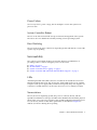
Netra™ 1290 Server System
Administration Guide
Sun Microsystems, Inc.
www.sun.com
Part No. 819-4374-10
May 2006, Revision A
Submit comments about this document at: http://www.sun.com/hwdocs/feedback
Copyright 2006 Sun Microsystems, Inc., 4150 Network Circle, Santa Clara, California 95054, U.S.A. All rights reserved.
Sun Microsystems, Inc. has intellectual property rights relating to technology that is described in this document. In particular, and without
limitation, these intellectual property rights may include one or more of the U.S. patents listed at http://www.sun.com/patents and one or
more additional patents or pending patent applications in the U.S. and in other countries.
This document and the product to which it pertains are distributed under licenses restricting their use, copying, distribution, and
decompilation. No part of the product or of this document may be reproduced in any form by any means without prior written authorization of
Sun and its licensors, if any.
Third-party software, including font technology, is copyrighted and licensed from Sun suppliers.
Parts of the product may be derived from Berkeley BSD systems, licensed from the University of California. UNIX is a registered trademark in
the U.S. and in other countries, exclusively licensed through X/Open Company, Ltd.
Sun, Sun Microsystems, the Sun logo, Java, Netra, OpenBoot, SunVTS, SunSolve, AnswerBook2, docs.sun.com, and Solaris are trademarks or
registered trademarks of Sun Microsystems, Inc. in the U.S. and in other countries.
All SPARC trademarks are used under license and are trademarks or registered trademarks of SPARC International, Inc. in the U.S. and in other
countries. Products bearing SPARC trademarks are based upon an architecture developed by Sun Microsystems, Inc.
The OPEN LOOK and Sun™ Graphical User Interface was developed by Sun Microsystems, Inc. for its users and licensees. Sun acknowledges
the pioneering efforts of Xerox in researching and developing the concept of visual or graphical user interfaces for the computer industry. Sun
holds a non-exclusive license from Xerox to the Xerox Graphical User Interface, which license also covers Sun’s licensees who implement OPEN
LOOK GUIs and otherwise comply with Sun’s written license agreements.
U.S. Government Rights—Commercial use. Government users are subject to the Sun Microsystems, Inc. standard license agreement and
applicable provisions of the FAR and its supplements.
DOCUMENTATION IS PROVIDED "AS IS" AND ALL EXPRESS OR IMPLIED CONDITIONS, REPRESENTATIONS AND WARRANTIES,
INCLUDING ANY IMPLIED WARRANTY OF MERCHANTABILITY, FITNESS FOR A PARTICULAR PURPOSE OR NON-INFRINGEMENT,
ARE DISCLAIMED, EXCEPT TO THE EXTENT THAT SUCH DISCLAIMERS ARE HELD TO BE LEGALLY INVALID.
Copyright 2006 Sun Microsystems, Inc., 4150 Network Circle, Santa Clara, Californie 95054, États-Unis. Tous droits réservés.
Sun Microsystems, Inc. possède les droits de propriété intellectuels relatifs à la technologie décrite dans ce document. En particulier, et sans
limitation, ces droits de propriété intellectuels peuvent inclure un ou plusieurs des brevets américains listés sur le site
http://www.sun.com/patents, un ou les plusieurs brevets supplémentaires ainsi que les demandes de brevet en attente aux les États-Unis et
dans d’autres pays.
Ce document et le produit auquel il se rapporte sont protégés par un copyright et distribués sous licences, celles-ci en restreignent l’utilisation,
la copie, la distribution, et la décompilation. Aucune partie de ce produit ou document ne peut être reproduite sous aucune forme, par quelque
moyen que ce soit, sans l’autorisation préalable et écrite de Sun et de ses bailleurs de licence, s’il y en a.
Tout logiciel tiers, sa technologie relative aux polices de caractères, comprise, est protégé par un copyright et licencié par des fournisseurs de
Sun.
Des parties de ce produit peuvent dériver des systèmes Berkeley BSD licenciés par l’Université de Californie. UNIX est une marque déposée
aux États-Unis et dans d’autres pays, licenciée exclusivement par X/Open Company, Ltd.
Sun, Sun Microsystems, le logo Sun, Java, Netra, OpenBoot, SunVTS, SunSolve, AnswerBook2, docs.sun.com, et Solaris sont des marques de
fabrique ou des marques déposées de Sun Microsystems, Inc. aux États-Unis et dans d’autres pays.
Toutes les marques SPARC sont utilisées sous licence et sont des marques de fabrique ou des marques déposées de SPARC International, Inc.
aux États-Unis et dans d’autres pays. Les produits portant les marques SPARC sont basés sur une architecture développée par Sun
Microsystems, Inc.
L’interface utilisateur graphique OPEN LOOK et Sun™ a été développée par Sun Microsystems, Inc. pour ses utilisateurs et licenciés. Sun
reconnaît les efforts de pionniers de Xerox dans la recherche et le développement du concept des interfaces utilisateur visuelles ou graphiques
pour l’industrie informatique. Sun détient une license non exclusive de Xerox sur l’interface utilisateur graphique Xerox, cette licence couvrant
également les licenciés de Sun implémentant les interfaces utilisateur graphiques OPEN LOOK et se conforment en outre aux licences écrites de
Sun.
LA DOCUMENTATION EST FOURNIE "EN L’ÉTAT" ET TOUTES AUTRES CONDITIONS, DÉCLARATIONS ET GARANTIES EXPRESSES
OU TACITES SONT FORMELLEMENT EXCLUES DANS LA LIMITE DE LA LOI APPLICABLE, Y COMPRIS NOTAMMENT TOUTE
GARANTIE IMPLICITE RELATIVE À LA QUALITÉ MARCHANDE, À L’APTITUDE À UNE UTILISATION PARTICULIÈRE OU À
L’ABSENCE DE CONTREFAÇON.
Please
Recycle
Contents
Preface
1.
xv
Netra 1290 Server Overview
Product Overview
1
1
Reliability, Availability, and Serviceability (RAS)
Reliability
5
5
Disabling Components or Boards and Power-On Self-Test (POST)
Manual Disabling of Components
Environmental Monitoring
Availability
6
6
6
Dynamic Reconfiguration
Power Failure
Host Watchdog
Serviceability
6
7
System Controller Reboot
LEDs
5
7
7
7
7
Nomenclature
7
System Controller Error Logging
8
System Controller XIR (eXternally Initiated Reset) Support
System Controller
8
8
iii
I/O Ports
8
System Management Tasks
Solaris Console
9
10
Environmental Monitoring
System Indicator Board
10
11
System Controller Message Logging
2.
Configuring the System Console
12
15
Establishing a LOM Console Connection
15
Accessing the LOM Console Using the Serial Port
15
▼
To Connect to an ASCII Terminal
16
▼
To Connect to a Network Terminal Server
▼
To Connect to Serial Port B of a Workstation
17
17
Accessing the LOM Console Through a Remote Connection
▼
To Access the LOM Console Using a Remote Connection
Disconnecting From the LOM Console
Switching Between the Consoles
18
19
20
▼
To Obtain the LOM Prompt From the Solaris Console
▼
To Connect to the Solaris Console From the LOM Prompt
▼
To Obtain the LOM Prompt From the OpenBoot PROM
22
▼
To Obtain the OpenBoot Prompt from the LOM Prompt
22
▼
To Obtain the OpenBoot Prompt When the Solaris OS Is Running
▼
To Terminate a Session When Connected to the System Controller
Through the Serial Port 23
▼
To Terminate a Session When Connected to the System Controller
Through a Network Connection 23
Solaris Command-Line Interface Commands
cfgadm Command
24
Command Options
▼
iv
18
24
To Display Basic Board Status
Netra 1290 Server System Administration Guide • May 2006
25
24
20
21
22
3.
▼
To Display Detailed Board Status
▼
To Test a CPU/Memory Board
▼
To Power Off a CPU/Memory Board Temporarily
▼
To Hot-Swap a CPU/Memory Board
Lights Out Management
LOM Command Syntax
26
27
29
31
32
Monitoring the System From the Solaris OS
32
▼
To View Online LOM Documentation
33
▼
To View the LOM Configuration
▼
To Check the Status of the Fault LED and Alarms
▼
To View the Event Log
▼
To Check the Fans
▼
To Check the Internal Voltage Sensors
▼
To Check the Internal Temperature
▼
To View All Component Status Data and the LOM Configuration Data
40
33
34
34
35
36
38
Other LOM Tasks Performed From the Solaris OS
4.
28
40
▼
To Turn Alarms On
40
▼
To Turn Alarms Off
41
▼
To Change the lom> Prompt Escape Sequence
▼
To Stop LOM From Sending Reports to the Console When at the LOM
Prompt 42
▼
To Upgrade the Firmware
Troubleshooting
42
43
Basic Troubleshooting
Power Distribution
▼
41
43
44
To Troubleshoot the Power Distribution System
Normal Operation
44
44
Contents
v
Abnormal Operation
Main Fans
45
45
System Controller
Interpreting LEDs
45
45
Server Enclosure LEDs
46
Board or Component LEDs
System Faults
48
49
Customer Replaceable Units
51
Disabling Components on a Board
51
Special Considerations for CPU/Memory Boards
▼
To Isolate a CPU/Memory Board
Recovering a Hung System
▼
53
54
To Recover a Hung Server Manually
Moving Server Identity
53
54
56
Power Supply Troubleshooting
56
CPU/Memory Troubleshooting
57
CPU/Memory Board Unconfiguration Failures
57
Cannot Unconfigure a Board Whose Memory Is Interleaved Across
Boards 58
Cannot Unconfigure a CPU to Which a Process is Bound
58
Cannot Unconfigure a CPU Before All Memory is Unconfigured
58
Unable to Unconfigure Memory on a Board With Permanent Memory
Memory Cannot Be Reconfigured
Not Enough Available Memory
Memory Demand Increased
59
59
59
Unable to Unconfigure a CPU
60
Unable to Disconnect a Board
60
CPU/Memory Board Configuration Failures
vi
Netra 1290 Server System Administration Guide • May 2006
60
59
Cannot Configure Either CPU0 or CPU1 While the Other Is Configured
60
CPUs on a Board Must Be Configured Before Memory
5.
Diagnostics
63
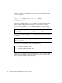
Power-On Self-Test
63
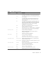
OpenBoot PROM Variables for POST Configuration
Controlling POST With the bootmode Command
Controlling the System Controller POST
▼
64
68
69
To Set the SC POST Diagnostic Level Default to min
SunVTS Software
72
To Check Temperature Conditions
72
Assisting Sun Service Personnel in Determining Causes of Failure
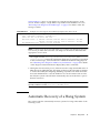
Automatic Diagnosis and Recovery Overview
Automatic Recovery of a Hung System
Diagnosis Events
75
77
79
Obtaining Auto-Diagnosis and Recovery Information
Reviewing Auto-Diagnosis Event Messages
Reviewing Component Status
Additional Troubleshooting Commands
Securing the Server
87
Security Guidelines
87
Defining the Console Password
80
81
82
Reviewing Additional Error Information
84
85
88
Using the SNMP Protocol Default Configuration
88
Rebooting the System Controller to Implement Settings
▼
75
78
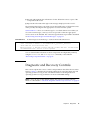
Diagnostic and Recovery Controls
6.
69
71
Diagnosing Environmental Conditions
▼
61
To Reboot the System Controller
88
88
Contents
vii
Selecting a Remote Connection Type
Enabling SSH
▼
89
89
To Enable SSH
90
Features Not Supported by SSH
Changing SSH Host Keys
91
92
Additional Security Considerations
92
Special Key Sequences for RTOS Shell Access
Domain Minimization
93
Solaris Operating System Security
A.
Dynamic Reconfiguration
Dynamic Reconfiguration
Quiescence
93
95
95
Command-Line Interface
DR Concepts
96
96
96
RPC or TCP Time-out or Loss of Connection
Suspend-Safe and Suspend-Unsafe Devices
Attachment Points
DR Operations
97
98
Hot-Plug Hardware
Conditions and States
98
99
Board States and Conditions
99
Board Receptacle States
99
Board Occupant States
100
Board Conditions
100
Component States and Conditions
Component Receptacle States
Component Occupant States
Component Conditions
viii
92
101
Netra 1290 Server System Administration Guide • May 2006
100
100
100
96
97
Component Types
101
Nonpermanent and Permanent Memory
Limitations
102
Memory Interleaving
102
Reconfiguring Permanent Memory
B.
101
Watchdog Timer Application Mode
102
103
Understanding the Watchdog Timer Application Mode
Watchdog Timer Unsupported Features and Limitations
Using the ntwdt Driver
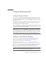
Using the Watchdog Timer
106
107
Setting the Timeout Period
107
Enabling or Disabling the Watchdog
Rearming the Watchdog
107
108
Getting the State of the Watchdog Timer
Finding and Defining Data Structures
Example Watchdog Program
Updating the Firmware
108
108
109
110
Watchdog Timer Error Messages
C.
104
106
Understanding the User API
Programming Alarm3
103
112
113
Using the flashupdate Command
113
▼
To Upgrade the Netra 1290 Server Firmware Using the flashupdate
Command 115
▼
To Downgrade the Netra 1290 Server Firmware Using the flashupdate
Command 115
Using the lom –G Command
▼
116
To Upgrade the Netra 1290 Server Firmware Using the lom –G
Command 117
Contents
ix
▼
D.
To Downgrade the Netra 1290 Server Firmware Using the lom –G
Command 118
Device Mapping
119
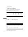
CPU/Memory Mapping
119
IB_SSC Assembly Mapping
x
120
Netra 1290 Server System Administration Guide • May 2006
Figures
FIGURE 1-1
Server Top View
2
FIGURE 1-2
Server Front View
FIGURE 1-3
Server Rear View 4
FIGURE 1-4
Server I/O Port Locations
FIGURE 1-5
System Indicator Board
FIGURE 1-6
System Controller Logging
FIGURE 2-1
Navigation Between Consoles
FIGURE 2-2
Details of the Output for the cfgadm -av Command
FIGURE 4-1
Server Front Panel LEDs
46
FIGURE 4-2
Server Rear Panel LEDs
48
FIGURE 4-3
System Indicators
FIGURE 5-1
Auto Diagnosis and Recovery Process
FIGURE D-1
Netra 1290 Server IB_SSC PCI+ Physical Slot Designations for IB6
3
9
11
13
20
27
50
76
123
xi
xii
Netra 1290 Server System Administration Guide • May 2006
Tables
TABLE 1-1
Selected System Controller Management Tasks
10
TABLE 1-2
System Indicator LED Functions
TABLE 2-1
DR Board States From the System Controller (SC)
TABLE 2-2
cfgadm -c Command Arguments
25
TABLE 2-3
cfgadm -x Command Arguments
25
TABLE 2-4
cfgadm Diagnostic Levels
TABLE 3-1
lom Command Options and Arguments
TABLE 4-1
FRU LED Status
TABLE 4-2
Server LED Functions
TABLE 4-3
LED Descriptions for Major Boards and the Main Fan Tray
TABLE 4-4
System Fault Indicator States
TABLE 4-5
Blacklisting Component Names
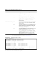
TABLE 5-1
POST Configuration Parameters
TABLE 5-2
SunVTS Documentation
TABLE 5-3
Diagnostic and Operating System Recovery Parameters
TABLE 5-4
Additional Troubleshooting Commands
TABLE 6-1
SSH Server Attributes
TABLE A-1
Types of DR Operation 98
TABLE A-2
Board Receptacle States
TABLE A-3
Board Occupant States
11
24
28
32
44
47
49
50
52
65
71
80
85
89
99
100
xiii
TABLE A-4
Board Conditions
TABLE A-5
Component Occupant States
TABLE A-6
Component Conditions
TABLE A-7
Component Types
TABLE B-1
Alarm3 Behavior
TABLE B-2
Watchdog Timer Error Messages
TABLE D-1
CPU and Memory Agent ID Assignment
120
TABLE D-2
I/O Assembly Type and Number of Slots
120
TABLE D-3
Number and Name of I/O Assemblies per System
TABLE D-4
I/O Controller Agent ID Assignments
TABLE D-5
IB_SSC Assembly PCI+ Device Mapping
xiv
100
101
101
101
110
112
121
Netra 1290 Server System Administration Guide • May 2006
122
120
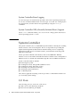
Preface
The Netra 1290 Server Administration Guide provides detailed procedures that enable
administration and troubleshooting of the Netra™ 1290 server. This document is
written for technicians, system administrators, authorized service providers (ASPs),
and users who have advanced experience administering and troubleshooting server
systems.
How This Document Is Organized
Chapter 1 provides a basic understanding of the features of the Netra 1290 server.
Chapter 2 describes connecting to the system and navigating between the LOM shell
and the console.
Chapter 3 explains how to use the LOM-specific commands.
Chapter 4 describes how to troubleshoot the server.
Chapter 5 describes diagnostics.
Chapter 6 provides important information about securing the system.
Appendix A describes how to dynamically reconfigure the CPU/memory boards.
Appendix B gives information on the watchdog timer application mode.
Appendix C explains how to update the server firmware.
Appendix D describes device mapping nomenclature.
xv
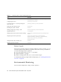
Using UNIX Commands
This document might not contain information about basic UNIX® commands and
procedures such as shutting down the system, booting the system, and configuring
devices. Refer to the following for this information:
■
Software documentation that you received with your system
■
Solaris™ Operating System documentation, which is at:
http://docs.sun.com
Shell Prompts
Shell
Prompt
C shell
machine-name%
C shell superuser
machine-name#
Bourne shell and Korn shell
$
Bourne shell and Korn shell superuser
#
Typographic Conventions
Typeface*
Meaning
Examples
AaBbCc123
The names of commands, files,
and directories; on-screen
computer output
Edit your.login file.
Use ls -a to list all files.
% You have mail.
AaBbCc123
What you type, when contrasted
with on-screen computer output
% su
Password:
AaBbCc123
Book titles, new words or terms,
words to be emphasized.
Replace command-line variables
with real names or values.
Read Chapter 6 in the User’s Guide.
These are called class options.
You must be superuser to do this.
To delete a file, type rm filename.
xvi Netra 1290 Server System Administration Guide • May 2006
* The settings on your browser might differ from these settings.
Related Documentation
The documents listed as online are available at:
http://www.sun.com/products-n-solutions/hardware/docs/
Application
Title
Part Number
Format
Location
Pointer doc
Netra 1290 Server Getting Started Guide
819-4378-10
Printed
PDF
Shipping kit
Online
Installation
Netra 1290 Server Installation Guide
819-4372-10
PDF
Online
Service
Netra 1290 Server Service Manual
819-4373-10
PDF
Online
Updates
Netra 1290 Server Product Notes
819-4375-10
PDF
Online
Compliance
Netra 1290 Server Safety and Compliance
Guide
819-4376-10
PDF
Online
Documentation, Support, and Training
Sun Function
URL
Documentation
http://www.sun.com/documentation/
Support
http://www.sun.com/support/
Training
http://www.sun.com/training/
Third-Party Web Sites
Sun is not responsible for the availability of third-party web sites mentioned in this
document. Sun does not endorse and is not responsible or liable for any content,
advertising, products, or other materials that are available on or through such sites
Preface
xvii
or resources. Sun will not be responsible or liable for any actual or alleged damage
or loss caused by or in connection with the use of or reliance on any such content,
goods, or services that are available on or through such sites or resources.
Sun Welcomes Your Comments
Sun is interested in improving its documentation and welcomes your comments and
suggestions. You can submit your comments by going to:
http://www.sun.com/hwdocs/feedback
Please include the title and part number of your document with your feedback:
Netra 1290 Server System Administration Guide, part number 819-4374-10
xviii
Netra 1290 Server System Administration Guide • May 2006
CHAPTER
1
Netra 1290 Server Overview
This chapter provides a basic understanding of the features of the Netra 1290 server
and describes the following topics:
■
■
■
“Product Overview” on page 1
“Reliability, Availability, and Serviceability (RAS)” on page 5
“System Controller” on page 8
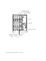
Product Overview
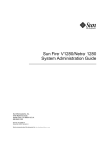
This section provides front, rear, and top views of the Netra 1290 server. FIGURE 1-1
shows a top view of the server where many boards and other devices are located.
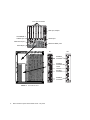
FIGURE 1-2 shows the interior front view of the server where power supplies, fans,
fan trays, and storage devices are located. FIGURE 1-3 shows the location of the ports,
connectors, and the power distribution board on the Netra 1290 server.
1
L2 repeater board, RP2
L2 repeater board, RP0
IB_SSC Assembly
Rear
I/O bay
IB fan cover
Media bay access door
Front
CPU/memory CPU/memory CPU/memory
board, SB2
board, SB0
board, SB4
FIGURE 1-1
2
Server Top View
Netra 1290 Server System Administration Guide • May 2006
System indicator
board
On/Standby switch
DVD-ROM drive
Tape drive
Fans
Hard drive 1
Fan tray
Hard drive 0
Power supply
PS3
Power supply
PS2
Power supply
PS1
Power supply
PS0
FIGURE 1-2
Server Front View
Chapter 1
Netra 1290 Server Overview
3
PCI+ 0-5 connectors
SCSI port, 68 pins
10/100BASE-T
LOM/SC port
Alarms port
LOM serial A port
NET0 and NET1 ports
Serial B port
AC
AC3/DC3
connection
SOURCE A
B
AC
3
DC
AC
2
AC2/DC2
connection
Power
inlet box
AC1/DC1
connection
SOURCE A
AC
1
AC
0
FIGURE 1-3
4
Server Rear View
Netra 1290 Server System Administration Guide • May 2006
AC0/DC0
connection
Reliability, Availability, and
Serviceability (RAS)
Reliability, availability, and serviceability (RAS) are features of this system.
■
Reliability is the probability that a system stays operational for a specified time
period when operating under normal environmental conditions. Reliability differs
from availability in that reliability involves only system failure, whereas
availability depends on both failure and recovery.
■
Availability, also known as average availability, is the percentage of time that a
system is available to perform its functions correctly. Availability can be measured
at the system level or in the context of the availability of a service to an end client.
The system availability imposes an upper limit on the availability of any products
built on top of that system.
■
Serviceability measures the ease and effectiveness of maintenance and server
repair for the product. There is no single well-defined metric, because
serviceability can include both Mean Time to Repair (MTTR) and diagnosability.
The following sections provide details on RAS.
Reliability
The software reliability features include:
■
■
■
“Disabling Components or Boards and Power-On Self-Test (POST)” on page 5
“Manual Disabling of Components” on page 6
“Environmental Monitoring” on page 6
The reliability features also improve system availability.
Disabling Components or Boards and Power-On Self-Test
(POST)
The power-on self-test (POST) is part of powering on the server. If the board or
component fails testing, POST disables components or boards. The showboards
command displays the board as either being failed or degraded. The server, running
the Solaris Operating System, is booted only with components that have passed
POST testing.
Chapter 1
Netra 1290 Server Overview
5
Manual Disabling of Components
The system controller provides component-level status and user-controlled
modification of component status.
Set the component location status by running the setls command from the console.
The component location status is updated at the next domain reboot, board power
cycle, or POST execution (for example, POST is run whenever you perform a
setkeyswitch on or off operation).
Note – The enablecomponent and disablecomponent commands have been
replaced by the setls command. These commands were formerly used to manage
component resources. While the enablecomponent and disablecomponent
commands are still available, use the setls command to control the configuration
of components into or out of the server.
The showcomponent command displays status information about the component,
including whether or not it has been disabled.
Environmental Monitoring
The system controller (SC) monitors the server’s temperature, cooling, and voltage
sensors. The SC provides the latest environmental status information to the Solaris
Operating System. If hardware needs to be powered off, the SC notifies the Solaris
OS to perform a system shutdown.
Availability
The software availability features include:
■
■
■
■
“Dynamic Reconfiguration” on page 6
“Power Failure” on page 7
“System Controller Reboot” on page 7
“Host Watchdog” on page 7
Dynamic Reconfiguration
The following components can be dynamically reconfigured:
■
■
■
■
6
Hard drives
CPU/memory boards
Power supplies
Fans
Netra 1290 Server System Administration Guide • May 2006
Power Failure
On recovery from a power outage, the SC attempts to restore the system to its
previous state.
System Controller Reboot
The SC can be rebooted and will start up and resume management of the system.
The reboot does not disturb the currently running Solaris Operating System.
Host Watchdog
The SC monitors the state of the Solaris Operating System and initiates a reset if the
system stops responding.
Serviceability
The software serviceability features promote the efficiency and timeliness of
providing routine as well as emergency service to the server.
■
■
■
■
“LEDs” on page 7
“Nomenclature” on page 7
“System Controller Error Logging” on page 8
“System Controller XIR (eXternally Initiated Reset) Support” on page 8
LEDs
All field-replaceable units (FRUs) that are accessible from outside the server have
LEDs that indicate their state. The SC manages all the LEDs in the server, with the
exception of the power supply LEDs, which are managed by the power supplies. For
a discussion of LED functions, see the Netra 1290 Server Service Manual, 819-4373.
Nomenclature
The SC, the Solaris Operating System, the power-on self-test (POST), and the
OpenBoot™ PROM error messages use FRU name identifiers that match the physical
labels in the server. The only exception is the OpenBoot PROM nomenclature used
for I/O devices, which use the device path names as described in Chapter 4 to
indicate I/O devices during device probing.
Chapter 1
Netra 1290 Server Overview
7
System Controller Error Logging
SC error messages are automatically reported to the Solaris Operating System. The
SC also has an internal buffer where error messages are stored. You can display the
SC logged events, stored in the SC message buffer, by using the showlogs
command.
System Controller XIR (eXternally Initiated Reset) Support
The SC reset command enables you to recover from a hung system and extract a
Solaris Operating System core file.
System Controller
The system controller (SC) is an embedded system resident on the IB_SSC assembly,
which connects to the server backplane. The SC is responsible for providing the
Lights Out Management (LOM) functions which include power-on sequencing,
sequencing module power-on self-tests (POST), environmental monitoring, fault
indication, and alarms.
The SC provides an RS-232 serial interface and one 10/100BASE-T Ethernet
interface. Access to the LOM command-line interface and the Solaris and OpenBoot
PROM consoles are shared and obtained through the serial and Ethernet interfaces.
System controller functions include:
■
■
■
■
■
■
Monitoring the system
Providing the Solaris and OpenBoot PROM consoles
Providing the virtual TOD (time of day)
Performing environmental monitoring
Performing system initialization
Coordinating POST
The software application running on the SC provides a command-line interface for
you to modify system settings.
I/O Ports
The following ports are on the rear of the server:
■
■
8
LOM console serial (RS-232) port (RJ-45)
Reserved serial (RS-232) port (RJ-45)
Netra 1290 Server System Administration Guide • May 2006
■
■
■
■
■
■
Two Gigabit Ethernet ports, NET0 and NET1(RJ-45)
Alarms port (DB-15)
System controller 10/100BASE-T Ethernet port (RJ-45)
UltraSCSI port
Up to six PCI+ ports (both 33 MHz and 66 MHz support)
Four power supply inputs
Their locations are shown in FIGURE 1-4.
PCI+ 0-5 slots
SCSI port, 68 pins
10/100BASE-T
LOM/SC port
Alarms port
LOM serial A port
NET0 and NET1 ports
Serial B port
FIGURE 1-4
Server I/O Port Locations
The LOM console serial port and 10/100BASE-T Ethernet port can be used to access
the system controller.
Use the console serial port to connect directly to an ASCII terminal or an NTS
(network terminal server). Connecting the System Controller board with a serial
cable enables you to access the system controller command line interface with an
ASCII terminal or an NTS.
Use the 10/100BASE-T Ethernet port to connect the SC to the network.
System Management Tasks
The LOM prompt provides the command-line interface for the SC. It is also the place
where console messages are displayed. Some of the system management tasks are
shown in TABLE 1-1.
Chapter 1
Netra 1290 Server Overview
9
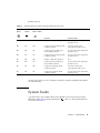
TABLE 1-1
Selected System Controller Management Tasks
Tasks
Commands
Configuring the system controller
password, setescape, seteventreporting,
setupnetwork, setupsc
Configuring the server
setalarm, setlocator
Powering boards on or off, and powering the
server on or off
poweron, poweroff, reset, shutdown
Testing the CPU/memory board
testboard
Resetting the system controller
resetsc
Marking components as faulty or OK
disablecomponent, enablecomponent
Upgrading firmware
flashupdate
Displaying the current system controller settings
showescape, showeventreporting, shownetwork,
showsc
Displaying the current system state
showalarm, showboards, showcomponent,
showenvironment, showfault, showhostname,
showlocator, showlogs, showmodel,
showresetstate
Setting the date, time, and time zone
setdate
Displaying the date and time
showdate
Solaris Console
If the Solaris Operating System, the OpenBoot PROM, or POST is running, you can
access the Solaris console. When you connect to the Solaris console, you will be in
one of the following modes of operation:
■
■
■
Solaris Operating System console (% or # prompts).
OpenBoot PROM (ok prompt).
System is running POST and you can view the POST output.
To switch between these prompts and the LOM prompt, see “Switching Between the
Consoles” on page 20.
Environmental Monitoring
Sensors monitor temperature, voltage, and fan operation.
10
Netra 1290 Server System Administration Guide • May 2006
The SC polls these sensors regularly and makes the environmental data available to
the Solaris OS. If necessary, the SC shuts down various components to prevent
damage in an over limit situation.
For instance, in the case of an overtemperature, the SC notifies the Solaris OS of the
overtemperature and the operating system takes action. In the case of extreme
overtemperature, the SC software can shut down the system without first notifying
the operating system.
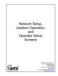
System Indicator Board
The system indicator board contains the On/Standby switch and indicator LEDs as
shown in FIGURE 1-5.
On/Standby
switch
SYSTEM
ALARM
POWER SOURCE
SERVICE REQUIRED
Locator
System active
System fault
FIGURE 1-5
UNIX running
or Alarm 3
Top access required
Source A and Source B
Alarm1 and Alarm2
System Indicator Board
The indicator LEDs function as shown in TABLE 1-2.
TABLE 1-2
System Indicator LED Functions
Name
Color
Function
Locator*
White
Normally off; can be lit by user command.
System Fault*
Amber
Lights when the LOM detects a fault.
System Active*
Green
Lights when power is applied to the server.
Top Access
Amber
Lights when a fault occurs in a FRU, which can only be replaced
from the top of the server.
Chapter 1
Netra 1290 Server Overview
11
TABLE 1-2
System Indicator LED Functions
Name
Color
Function
UNIX Running
Green
Lights when the Solaris OS is running. Off while the server is
powering up. Can be reset by watchdog timeout, or by assertion of
user-defined Alarm3 (for further information, see “Programming
Alarm3” on page 110.
Alarm1 and Alarm2
Green
Lights when triggered by events as specified in the LOM.
Source A and Source B
Green
Lights when the relevant power feeds are present.
* This indicator is duplicated on the rear of the server.
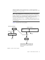
System Controller Message Logging
The SC generates timestamped messages for system events, processes such as
powering on, booting, powering off, changes to hot-pluggable units, and
environmental warnings.
The messages are initially stored in the SC on-board memory in a circular 128message buffer. A single message can span multiple lines. In addition, the SC sends
the messages to the Solaris host when it is running Solaris software, and these are
processed by the system log daemon (syslogd). When Solaris software is running,
messages are sent at the time they are generated by the SC. Retrieval of messages not
already copied from the SC takes place at Solaris OS boot time or when the SC is
reset.
Messages can also be displayed at the Solaris prompt by using the lom(1M) utility
(see Chapter 3).
Typically, the messages are stored on the Solaris host in the /var/adm/messages
file, the only limiting factor being the available disk space.
Messages that are held in the SC message buffer are volatile. Messages are not
retained if:
■
■
■
■
Power is removed from the SC by loss of both power sources
Less than two power supplies are operational
The IB_SSC is removed
The SC is reset
Messages stored on the system disk are available when the Solaris OS is rebooted.
The display of the messages on the shared Solaris/SC console port, when at the
lom> prompt, is controlled by the seteventreporting command (see the Sun Fire
Entry-Level Midrange System Controller Command Reference Manual, 819-1268). This
12
Netra 1290 Server System Administration Guide • May 2006
determines whether a message is printed at the lom> prompt at the time the
message is logged, and also whether it is posted to the Solaris logging system so that
it is written to /var/adm/messages.
Note – Servers equipped with the enhanced memory SC (also known as SC V2),
have an additional 112 Kbytes area of SC memory that is used to store firmware
messages. This memory is nonvolatile; messages stored there are not deleted when
the SC is powered off. The original LOM history buffer is dynamic, losing
information when powered off. The messages stored in the persistent history logs of
the SC V2 can be displayed at the lom> prompt by using the showlogs –p
command or the showerrorbuffer –p command. See the appropriate sections in
Sun Fire Entry-Level Midrange System Controller Command Reference Manual, 819-1268,
for the descriptions.
FIGURE 1-6 illustrates the two message buffers.
Main server hardware
System controller
Main CPU
LOM history log in ring Persistent LOM history log
buffer
Solaris messages
Discard
/var/adm/messages
LOM writes message
Discard
LOM port
LOM commands gain access to history log
whenever system is On or in Standby mode
(that is, the system controller not broken or
unpowered)
FIGURE 1-6
System Controller Logging
Chapter 1
Netra 1290 Server Overview
13
14
Netra 1290 Server System Administration Guide • May 2006
CHAPTER
2
Configuring the System Console
This chapter explains step-by-step procedures and provides illustrations for
connecting to the system and navigating between the LOM shell and the console. It
also explains how to terminate an SC session.
This chapter includes the following topics:
■
■
■
“Establishing a LOM Console Connection” on page 15
“Switching Between the Consoles” on page 20
“Solaris Command-Line Interface Commands” on page 24
Establishing a LOM Console Connection
There are two ways to access the LOM console connection:
■
■
Through the SC serial port (direct) connection
Through a Telnet (network) connection using the 10/100BASE-T Ethernet port
Under normal operation connecting to the LOM console automatically selects a
connection to the Solaris console, otherwise a connection to the LOM prompt is
made.
The LOM prompt is:
lom>
Accessing the LOM Console Using the Serial Port
With the serial port, you can connect to one of three devices:
15
■
■
■
ASCII terminal
Network terminal server
Workstation
See the Netra 1290 Server Installation Guide, 819-4372, for details of how to make the
physical connections. The procedure is different for each type of device.
▼ To Connect to an ASCII Terminal
If the LOM password has been set and the previous connection was logged out, you
are prompted for a password.
● Enter the correct password as previously set up using the password command.
Enter Password:
■
If the password is accepted, the SC indicates that a connection has been made.
■
If the server is in Standby mode, the lom prompt is automatically displayed.
Connected.
lom>
■
If the server is not in standby mode, press Return and the Solaris console prompt
is displayed.
Connected.
#
■
16
If a connection to the LOM console is already established over the network port,
then you can force the connection by logging out of the other connection:
Netra 1290 Server System Administration Guide • May 2006
Enter Password:
The console is already in use.
Host:
somehost.acme.com
Connected: May 24 10:27
Idle time: 00:23:17
Force logout of other user? (y/n) y
Connected.
lom>
Otherwise press Return and the Solaris console prompt is displayed.
Connected.
#
▼ To Connect to a Network Terminal Server
1. You are provided with a menu of various servers to which you can connect. Select
the required server.
2. See the procedure: “To Connect to an ASCII Terminal” on page 16.
▼ To Connect to Serial Port B of a Workstation
1. At the Solaris shell prompt type:
# tip hardwire
See the tip man page for a complete description of the tip command.
If the LOM password has been set and the previous connection was logged out, you
will be prompted for a password.
2. See the procedure: “To Connect to an ASCII Terminal” on page 16.
Chapter 2
Configuring the System Console
17
Accessing the LOM Console Through a Remote
Connection
▼ To Access the LOM Console Using a Remote Connection
In order to be able to access the LOM console through a remote connection (for
example: an SSH connection) to the 10/100BASE-T Ethernet port you must first set
up the interface.
Refer to the Netra 1290 Server Installation Guide, 819-4372.
1. Type the ssh command at the Solaris prompt to connect to the SC.
% ssh hostname
2. If the LOM password has been set up you are prompted for a password.
# Enter password:
3. Enter the correct password as previously set up using the password command.
■
If the password is accepted the SC indicates that a connection has been made.
■
If the server is in Standby mode the lom prompt is automatically displayed.
Connected.
lom>
■
If the server is not in standby mode, press Return and the Solaris console prompt
will be displayed.
Connected.
#
■
18
If a connection to the LOM console is already established over the serial port, type
n to cancel the forced logout.
Netra 1290 Server System Administration Guide • May 2006
# ssh hostname
The console is already in use.
Host:
somehost.acme.com
Connected: May 24 10:27
Idle time: 00:23:17
Force logout of other user? (y/n) y
Connected.
lom>
In this case you should first use the LOM logout command on the serial connection
to make the connection available, rather than the forced logout. Refer to the
following section for further details.
Disconnecting From the LOM Console
When you have finished using the LOM console you can disconnect by using the
logout command.
On the serial port the response is:
lom>logout
Connection closed.
When connected over the network the response is:
lom>logout
Connection closed.
Connection to hostname closed by remote host.
Connection to hostname closed.Connection closed.
$
Chapter 2
Configuring the System Console
19
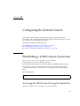
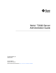
Switching Between the Consoles
The system controller (SC) console connection provides access to the SC LOM
command-line interface, the Solaris OS, and the OpenBoot PROM.
This section describes the procedures to navigate between the following:
■
■
■
LOM prompt
Solaris OS
OpenBoot PROM
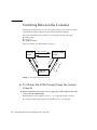
These procedures are summarized in FIGURE 2-1
Type: init 0
Solaris OS
prompt: #
OpenBoot PROM
prompt: ok
p
Ty
#.
Type: boot
e:
co
ns
ol
e
▼
Ty
or pe:
br
Ty
ea
pe
k
: c
on
so
le
#.
Ty
p
e:
e:
p
Ty
FIGURE 2-1
LOM shell
prompt: lom>
Navigation Between Consoles
To Obtain the LOM Prompt From the Solaris
Console
● When connected to the Solaris console, typing the escape sequence takes the
console into the LOM prompt.
By default the escape sequence is set to #.. (a # sign followed by a period)
For instance, if the escape sequence is the default of #. you will type:
20
Netra 1290 Server System Administration Guide • May 2006
# #.
lom>
Note – Unlike the example, you will not see the #. being typed.
When you type the first character of the escape sequence, there is a one second delay
before the character appears on the screen. During this interval, you must type the
second character of the escape sequence. If the escape sequence is completed within
the one-second interval, the lom> prompt appears. Any characters typed after the
second escape character are appended to the lom> prompt.
If the second escape character is incorrect, or is typed after the one-second interval
has expired, then all characters are output at the original prompt.
To change the escape character sequence, see “To Change the lom> Prompt Escape
Sequence” on page 41.
▼
To Connect to the Solaris Console From the
LOM Prompt
● Use the console command from the LOM prompt, then type a carriage return.
■
If Solaris software is running, the system responds with the Solaris prompt:
lom>console
#
■
If the system was in the OpenBoot PROM, then the system responds with the
OpenBoot PROM prompt:
lom>console
{2} ok
■
If the server is in Standby mode, the following message is generated:
lom>console
Solaris is not active
Chapter 2
Configuring the System Console
21
Note – The console command first attempts to connect to the Solaris console. If it
is not available, the console command then attempts to connect to the OpenBoot
PROM. If unsuccessful, the message: Solaris is not active, is displayed.
▼
To Obtain the LOM Prompt From the OpenBoot
PROM
● Type the sequence of escape characters (default #.).
{2} ok #.
lom>
Note – Unlike the example, you will not see the #. being typed.
▼
To Obtain the OpenBoot Prompt from the LOM
Prompt
● Type the break command.
lom> break
{2} ok
▼
To Obtain the OpenBoot Prompt When the
Solaris OS Is Running
● Type the init 0 command at the Solaris prompt:
# init 0
{1} ok
22
Netra 1290 Server System Administration Guide • May 2006
▼
To Terminate a Session When Connected to the
System Controller Through the Serial Port
■
If you are at the Solaris console or the OpenBoot PROM go to LOM prompt by
typing the escape sequence, then terminate the LOM prompt session by typing
logout and pressing Return:
lom>logout
■
If you are connected through a terminal server invoke the terminal server’s
command to disconnect the connection.
■
If the connection was established using a tip command then type the tip exit
sequence ~.(tilde and a period):
~.
▼
To Terminate a Session When Connected to the
System Controller Through a Network
Connection
1. If you are at the Solaris prompt or the OpenBoot PROM, go to the LOM prompt
by typing the escape sequence.
2. Terminate the LOM prompt session by using the logout command.
The remote session terminates automatically:
lom>logout
Connection closed by foreign host.
%
Chapter 2
Configuring the System Console
23
Solaris Command-Line Interface
Commands
Many server hardware administration tasks can be achieved by using Solaris
commands at the command-line interface. Some of those procedures are discussed in
this section:
■
■
■
■
■
■
“cfgadm Command” on page 24
“To Display Basic Board Status” on page 25
“To Display Detailed Board Status” on page 26
“To Test a CPU/Memory Board” on page 27
“To Power Off a CPU/Memory Board Temporarily” on page 28
“To Hot-Swap a CPU/Memory Board” on page 29
Note – There is no need to enable dynamic reconfiguration explicitly. DR is enabled by
default.
cfgadm Command
The cfgadm(1M) command provides configuration administration operations on
dynamically reconfigurable hardware resources. TABLE 2-1 lists the DR board states.
TABLE 2-1
Board States
DR Board States From the System Controller (SC)
Description
Available
The slot is not assigned.
Assigned
The board is assigned, but the hardware has not been configured to
use it. The board may be reassigned by the chassis port or released.
Active
The board is being actively used. You cannot reassign an active
board.
Command Options
The arguments to the cfgadm -c command are listed in TABLE 2-2.
24
Netra 1290 Server System Administration Guide • May 2006
TABLE 2-2
cfgadm -c Command Arguments
cfgadm -c Argument
Function
connect
The slot provides power to the board and begins monitoring the
board. The slot is assigned if it was not previously assigned.
disconnect
The system stops monitoring the board, and power to the slot is
turned off.
configure
The operating system assigns functional roles to a board, and loads
device drivers for the board and for the devices attached to the
board.
unconfigure
The system detaches a board logically from the operating system
and takes the associated device drivers offline. Environmental
monitoring continues, but any devices on the board are not available
for system use.
The arguments to the cfgadm -x command are listed in TABLE 2-3.
TABLE 2-3
cfgadm -x Command Arguments
cfgadm -x Argument
Function
poweron
Powers on a CPU/memory board.
poweroff
Powers off a CPU/memory board.
The cfgadm_sbd man page provides additional information on the cfgadm -c
and cfgadm -x options. The sbd library provides the functionality for hotplugging system boards of the class sbd, through the cfgadm framework.
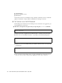
▼
To Display Basic Board Status
The cfgadm program displays information about boards and slots. See the
cfgadm(1M) man page for options to this command.
Many operations require that you specify the system board names.
● To obtain these system board names, type:
# cfgadm
Chapter 2
Configuring the System Console
25
When used without options, cfgadm displays information about all known
attachment points, including board slots and SCSI buses. The following display
shows a typical output.
CODE EXAMPLE 2-1
# cfgadm
Ap_Id
N0.IB6
N0.SB0
N0.SB2
N0.SB4
c0
c1
c2
Sample Output of the Basic cfgadm Command
Type
Receptacle
Occupant
Condition
PCI+_I/O_Bo connected
configured
ok
CPU_V3
disconnected unconfigured unknown
CPU_V3
connected
configured
ok
unknown
empty
unconfigured unknown
scsi-bus
connected
configured
unknown
scsi-bus
connected
unconfigured unknown
scsi-bus
connected
configured
unknown
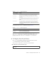
▼
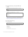
To Display Detailed Board Status
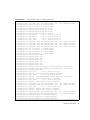
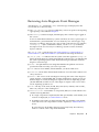
● Use the command cfgadm -av for a more detailed status report.
The -a option lists attachment points and the -v option turns on expanded
(verbose) descriptions.
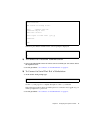
CODE EXAMPLE 2-2 is a partial display produced by the cfgadm -av command. The
output appears complicated because the lines wrap around in this display. This
status report is for the same server used in CODE EXAMPLE 2-1.
CODE EXAMPLE 2-2
Output of the cfgadm -av Command
# cfgadm -av
Ap_Id Receptacle
Occupant
Condition Information
When
Type
Busy
Phys_Id
N0.IB6 connected
configured
ok
powered-on, assigned
Feb 9 13:38 PCI+_I/O_Bo n
/devices/ssm@0,0:N0.IB6
N0.IB6::pci0 connected
configured
ok
device /ssm@0,0/pci@19,700000
Feb 9 13:38 io
n
/devices/ssm@0,0:N0.IB6::pci0
N0.IB6::pci1 connected
configured
ok
device /ssm@0,0/pci@19,600000
Feb 9 13:38 io
n
/devices/ssm@0,0:N0.IB6::pci1
N0.IB6::pci2 connected
configured
ok
device /ssm@0,0/pci@18,700000,
referenced
Feb 9 13:38 io
n
/devices/ssm@0,0:N0.IB6::pci2
N0.IB6::pci3 connected
configured
ok
device /ssm@0,0/pci@18,600000
Feb 9 13:38 io
n
/devices/ssm@0,0:N0.IB6::pci3
N0.SB0 disconnected unconfigured unknown
assigned
Feb 16 13:39 CPU_V3
y
/devices/ssm@0,0:N0.SB0
26
Netra 1290 Server System Administration Guide • May 2006
Output of the cfgadm -av Command (Continued)
CODE EXAMPLE 2-2
N0.SB2 connected
configured
ok
powered-on, assigned
Feb 16 10:13 CPU_V3
n
/devices/ssm@0,0:N0.SB2
N0.SB2::cpu0 connected
configured
ok
cpuid 8 and 520, speed 1500
MHz, ecache 32 MBytes
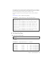
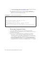
FIGURE 2-2 shows details of the display in CODE EXAMPLE 2-2:
Occupant state
Attachment
point ID
Receptacle state
Board/Component
information
Condition
N0.IB6
connected
configured
ok
powered-on, assigned
Feb 9 13:38 PCI+_I/O_Bo n
/devices/ssm@0,0:N0.IB6
When connected
Busy state
Physical ID and location
Board/Component
type
FIGURE 2-2
Details of the Output for the cfgadm -av Command
▼
To Test a CPU/Memory Board
Note – Before you can test a CPU/memory board, it must be powered on but
disconnected. If these conditions are not met, the board test fails.
1. Disconnect but do not power off the board using the cfgadm command as
superuser:
# cfgadm -c disconnect -o nopoweroff ap-id
where ap-id is one of the following: N0.SB0, N0.SB2 or N0.SB4.
2. Test the board:
Chapter 2
Configuring the System Console
27
# cfgadm -o platform=diag=level -t ap-id
where:
■
level is a diagnostic level described in TABLE 2-4.
■
ap-id is one of the following: N0.SB0, N0.SB2 or N0.SB4.
TABLE 2-4
▼
cfgadm Diagnostic Levels
Diagnostic Level
Description
init
Only system board initialization code is run. No testing is done. This
is a very fast pass through POST. This is the default level if not
specified.
quick
All system board components are tested with few tests and test
patterns.
min
Core functionalities of all system board components are tested. This
testing performs a quick sanity check of the devices under test.
default
All system board components are tested with all tests and test
patterns, except for memory and ecache modules. Note that max and
default are the same definition and that default is not the
default value.
max
All system board components are tested with all tests and test
patterns, except for memory and ecache modules. Note that max and
default are the same definition.
mem1
Runs all tests at the default level, plus more exhaustive DRAM
and SRAM test algorithms. For memory and ecache modules, all
locations are tested with multiple patterns. More extensive, timeconsuming algorithms are not run at this level.
mem2
The same as mem1, with the addition of a DRAM test that does
explicit compare operations of the DRAM data.
To Power Off a CPU/Memory Board
Temporarily
If the CPU/memory board fails and a replacement board or a filler board is not
available, you can use the cfgadm command to power off the board.
● Detach and power off the board using the cfgadm command as superuser.
28
Netra 1290 Server System Administration Guide • May 2006
# cfgadm -c disconnect ap-id
where ap-id is one of the following: N0.SB0, N0.SB2 or N0.SB4.
▼
To Hot-Swap a CPU/Memory Board
Hot-swapping the CPU/memory board is equivalent to removing and installing a
board. Refer to the Netra 1290 Server Service Manual, 819-4373, for instructions.
Chapter 2
Configuring the System Console
29
30
Netra 1290 Server System Administration Guide • May 2006
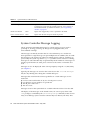
CHAPTER
3
Lights Out Management
This chapter explains how to use the LOM-specific commands available in the
Solaris OS for monitoring and managing a Netra 1290 server. To use these
commands, you should install the Lights Out Management 2.0 packages (SUNWlomr,
SUNWlomu and SUNWlomm).
These packages are available from the Solaris software download center at:
http://www.sun.com/download/
Under Systems Administration, click on the Systems Management link.
Note – The latest patches to these packages is available from SunSolve in patch
110208. It is strongly advised that the latest version of patch 110208 be obtained from
SunSolve and be installed on the Netra 1290 server to make use of the latest LOM
utility updates.
Topic in this chapter include:
■
■
■
“LOM Command Syntax” on page 32
“Monitoring the System From the Solaris OS” on page 32
“Other LOM Tasks Performed From the Solaris OS” on page 40
31
LOM Command Syntax
TABLE 3-1 summarizes the options and arguments of the lom command.
TABLE 3-1
lom Command Options and Arguments
lom Option
Description
-A on|off number
Turns alarm number on or off. number is either 1 or 2
-a
Displays all component status data.
-c
Displays LOM configuration.
-E on|off
Switches event logging to the console on or off.
-e number, level
Displays the event log for number of lines of event level. level is 1, 2, or 3.
-f
Displays fan status. This information is also displayed in the output from the
Solaris prtdiag -v command.
-G firmwarefilename
Upgrades the firmware with firmwarefilename.
-l
Displays the status of the Fault and Alarms LEDs.
-t
Displays temperature information. This information is also displayed in the
output from the Solaris prtdiag -v command.
-v
Displays the status of the voltage sensors. This information is also displayed in
the output from the Solaris prtdiag -v command.
-X xy
Changes the escape sequence to xy.
Monitoring the System From the Solaris
OS
There are two ways of interrogating the LOM device (SC) or of sending it commands
to perform:
■
By executing LOM commands from the lom> shell prompt.
■
By executing LOM-specific Solaris commands as superuser as described in this
chapter.
The Solaris commands described in this section are run from the /usr/sbin/lom
utility.
32
Netra 1290 Server System Administration Guide • May 2006
Monitoring procedures in this section include:
■
■
■
■
■
■
■
■
“To View Online LOM Documentation” on page 33
“To View the LOM Configuration” on page 33
“To Check the Status of the Fault LED and Alarms” on page 34
“To View the Event Log” on page 34
“To Check the Fans” on page 35
“To Check the Internal Voltage Sensors” on page 36
“To Check the Internal Temperature” on page 38
“To View All Component Status Data and the LOM Configuration Data” on
page 40
Where appropriate, the commands in this section are accompanied by typical output
from the commands.
▼
To View Online LOM Documentation
● To view the manual pages for the LOM utility, type:
# man lom
▼
To View the LOM Configuration
● To view the current LOM configuration, type:
# lom -c
For example:
CODE EXAMPLE 3-1
Sample Output from the lom -c Command
# lom -c
LOM configuration settings:
serial escape sequence=#.
serial event reporting=default
Event reporting level=fatal, warning & information
firmware version=5.20.0, build 13.0
product ID=Netra T12
Chapter 3
Lights Out Management
33
▼
To Check the Status of the Fault LED and
Alarms
● To check whether the System Fault LED and alarms are on or off, type:
# lom -l
For example:
CODE EXAMPLE 3-2
Sample Output from the lom -l Command
# lom -l
LOM alarm states:
Alarm1=off
Alarm2=off
Alarm3=on
Fault LED=off
#
Alarms1 and Alarm2 are software flags. They are associated with no specific
conditions but can be set by your own processes or from the command line (see “To
Turn Alarms On” on page 40). For information about Alarm3 (the system alarm) and
its relation to the watchdog timer, see “Programming Alarm3” on page 110.
▼
To View the Event Log
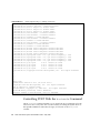
● To see the event log, type:
# lom -e n,[x]
where n is the number of reports (up to 128) that you want to see and x specifies the
level of reports you are interested in. There are four levels of event:
1. Fatal events
2. Warning events
3. Information events
4. User events (not used on Netra 1290 servers)
34
Netra 1290 Server System Administration Guide • May 2006
If you specify a level, you will see reports for that level and above. For example, if
you specify level 2, you will see reports of level 2 and level 1 events. If you specify
level 3, you will see reports of level 3, level 2, and level 1 events.
If you do not specify a level, you will see reports of level 3, level 2, and level 1
events.
CODE EXAMPLE 3-3 shows a sample event log display.
CODE EXAMPLE 3-3
Sample LOM Event Log – Oldest Event Reported First
# lom -e 11
LOMlite Event Log:
Tue Feb 21 07:53:53 commando-sc lom: Boot: ScApp 5.20.0, RTOS 45
Tue Feb 21 07:54:02 commando-sc lom: Caching ID information
Tue Feb 21 07:54:03 commando-sc lom: Clock Source: 75MHz
Tue Feb 21 07:54:07 commando-sc lom: /N0/PS0: Status is OK
Tue Feb 21 07:54:08 commando-sc lom: /N0/PS1: Status is OK
Tue Feb 21 07:54:08 commando-sc lom: /N0/PS2: Status is OK
Tue Feb 21 07:54:09 commando-sc lom: /N0/PS3: Status is OK
Tue Feb 21 07:54:09 commando-sc lom: Chassis is in single
partition mode.
Tue Feb 21 07:55:12 commando-sc lom: Starting telnet server ...
Tue Feb 21 07:55:12 commando-sc lom: Starting telnet server ...
Tue Feb 21 08:00:02 commando-sc lom: Locator OFF
▼
To Check the Fans
● To check status of the fans, type:
# lom -f
For example:
CODE EXAMPLE 3-4
# lom -f
Fans:
1 FT0/FAN0
2 FT0/FAN1
3 FT0/FAN2
4 FT0/FAN3
5 FT0/FAN4
6 FT0/FAN5
7 FT0/FAN6
Sample Output From the lom -f Command
ft_fan0
ft_fan1
ft_fan2
ft_fan3
ft_fan4
ft_fan5
ft_fan6
OK
OK
OK
OK
OK
OK
OK
speed
speed
speed
speed
speed
speed
speed
Chapter 3
self-regulating
self-regulating
self-regulating
self-regulating
self-regulating
self-regulating
self-regulating
Lights Out Management
35
CODE EXAMPLE 3-4
8 FT0/FAN7
9 IB6/FAN0
10 IB6/FAN1
#
Sample Output From the lom -f Command (Continued)
ft_fan7
ft_fan0
ft_fan1
OK
speed self-regulating
OK
speed
100 %
OK
speed
100 %
If you need to replace a fan, contact your local Sun sales representative and quote
the part number of the component you need. For information, see the Netra 1290
Server Service Manual, 819-4374.
The information output from this command is also contained in the output from the
Solaris prtdiag -v command.
▼
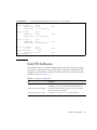
To Check the Internal Voltage Sensors
The -v option displays the status of the Netra 1290 server internal voltage sensors.
● To check the status of the supply rails and internal voltage sensors, type:
# lom -v
CODE EXAMPLE 3-5
Sample Output From the lom -v Command
# lom -v
Supply voltages:
1 SSC1
v_1.5vdc0
2 SSC1
v_3.3vdc0
3 SSC1
v_5vdc0
4 RP0
v_1.5vdc0
5 RP0
v_3.3vdc0
6 RP2
v_1.5vdc0
7 RP2
v_3.3vdc0
8 SB0
v_1.5vdc0
9 SB0
v_3.3vdc0
10 SB0/P0
v_cheetah0
11 SB0/P1
v_cheetah1
12 SB0/P2
v_cheetah2
13 SB0/P3
v_cheetah3
14 SB2
v_1.5vdc0
15 SB2
v_3.3vdc0
16 SB2/P0
v_cheetah0
17 SB2/P1
v_cheetah1
18 SB2/P2
v_cheetah2
19 SB2/P3
v_cheetah3
36
status=ok
status=ok
status=ok
status=ok
status=ok
status=ok
status=ok
status=ok
status=ok
status=ok
status=ok
status=ok
status=ok
status=ok
status=ok
status=ok
status=ok
status=ok
status=ok
Netra 1290 Server System Administration Guide • May 2006
CODE EXAMPLE 3-5
Sample Output From the lom -v Command (Continued)
20 IB6
v_1.5vdc0
status=ok
21 IB6
v_3.3vdc0
status=ok
22 IB6
v_5vdc0
status=ok
23 IB6
v_12vdc0
status=ok
24 IB6
v_3.3vdc1
status=ok
25 IB6
v_3.3vdc2
status=ok
26 IB6
v_1.8vdc0
status=ok
27 IB6
v_2.4vdc0
status=ok
System status flags:
1 PS0
status=okay
2 PS1
status=okay
3 FT0
status=okay
4 FT0/FAN0
status=okay
5 FT0/FAN1
status=okay
6 FT0/FAN2
status=okay
7 FT0/FAN3
status=okay
8 FT0/FAN4
status=okay
9 FT0/FAN5
status=okay
10 FT0/FAN6
status=okay
11 FT0/FAN7
status=okay
12 RP0
status=okay
13 RP2
status=okay
14 SB0
status=ok
15 SB0/P0
status=online
16 SB0/P0/B0/D0 status=okay
17 SB0/P0/B0/D1 status=okay
18 SB0/P0/B0/D2 status=okay
19 SB0/P0/B0/D3 status=okay
20 SB0/P1
status=online
21 SB0/P1/B0/D0 status=okay
22 SB0/P1/B0/D1 status=okay
23 SB0/P1/B0/D2 status=okay
24 SB0/P1/B0/D3 status=okay
25 SB0/P2
status=online
26 SB0/P2/B0/D0 status=okay
27 SB0/P2/B0/D1 status=okay
28 SB0/P2/B0/D2 status=okay
29 SB0/P2/B0/D3 status=okay
30 SB0/P3
status=online
31 SB0/P3/B0/D0 status=okay
32 SB0/P3/B0/D1 status=okay
33 SB0/P3/B0/D2 status=okay
34 SB0/P3/B0/D3 status=okay
35 SB2
status=ok
36 SB2/P0
status=online
37 SB2/P0/B0/D0 status=okay
38 SB2/P0/B0/D1 status=okay
Chapter 3
Lights Out Management
37
CODE EXAMPLE 3-5
39
40
41
42
43
44
45
46
47
48
49
50
51
52
53
54
55
56
57
58
#
Sample Output From the lom -v Command (Continued)
SB2/P0/B0/D2 status=okay
SB2/P0/B0/D3 status=okay
SB2/P1
status=online
SB2/P1/B0/D0 status=okay
SB2/P1/B0/D1 status=okay
SB2/P1/B0/D2 status=okay
SB2/P1/B0/D3 status=okay
SB2/P2
status=online
SB2/P2/B0/D0 status=okay
SB2/P2/B0/D1 status=okay
SB2/P2/B0/D2 status=okay
SB2/P2/B0/D3 status=okay
SB2/P3
status=online
SB2/P3/B0/D0 status=okay
SB2/P3/B0/D1 status=okay
SB2/P3/B0/D2 status=okay
SB2/P3/B0/D3 status=okay
IB6
status=ok
IB6/FAN0
status=okay
IB6/FAN1
status=okay
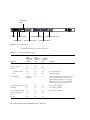
The information output from this command is also contained in the output from the
Solaris prtdiag -v command.
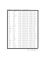
▼
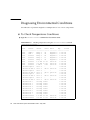
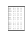
To Check the Internal Temperature
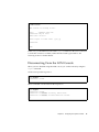
● To check the internal temperature of the server and also the server’s warning and
shutdown threshold temperatures, type:
# lom -t
For example:
CODE EXAMPLE 3-6
Sample Output From the lom -t Command
# lom -t
System Temperature Sensors:
1 SSC1
t_sbbc0
2 SSC1
t_cbh0
3 SSC1
t_ambient0
4 SSC1
t_ambient1
5 SSC1
t_ambient2
38
36
45
23
21
28
degC
degC
degC
degC
degC
:
:
:
:
:
warning
warning
warning
warning
warning
Netra 1290 Server System Administration Guide • May 2006
102 degC : shutdown 107 degC
102 degC : shutdown 107 degC
82 degC : shutdown 87 degC
82 degC : shutdown 87 degC
82 degC : shutdown 87 degC
CODE EXAMPLE 3-6
6
7
8
9
10
11
12
13
14
15
16
17
18
19
20
21
22
23
24
25
26
27
28
29
30
31
32
33
34
35
36
37
38
39
40
41
42
43
44
45
46
47
48
49
50
51
52
RP0
RP0
RP0
RP0
RP0
RP0
RP2
RP2
RP2
RP2
RP2
RP2
SB0
SB0
SB0
SB0
SB0
SB0
SB0
SB0
SB0/P0
SB0/P0
SB0/P1
SB0/P1
SB0/P2
SB0/P2
SB0/P3
SB0/P3
SB2
SB2
SB2
SB2
SB2
SB2
SB2
SB2
SB2/P0
SB2/P0
SB2/P1
SB2/P1
SB2/P2
SB2/P2
SB2/P3
SB2/P3
IB6
IB6
IB6
Sample Output From the lom -t Command (Continued)
t_ambient0
t_ambient1
t_sdc0
t_ar0
t_dx0
t_dx1
t_ambient0
t_ambient1
t_sdc0
t_ar0
t_dx0
t_dx1
t_sdc0
t_ar0
t_dx0
t_dx1
t_dx2
t_dx3
t_sbbc0
t_sbbc1
Ambient
Die
Ambient
Die
Ambient
Die
Ambient
Die
t_sdc0
t_ar0
t_dx0
t_dx1
t_dx2
t_dx3
t_sbbc0
t_sbbc1
Ambient
Die
Ambient
Die
Ambient
Die
Ambient
Die
t_ambient0
t_ambient1
t_sdc0
22
22
62
47
62
65
23
22
57
42
53
56
48
39
49
54
57
53
53
40
29
57
27
51
27
53
29
50
51
40
52
54
61
53
52
42
27
54
26
53
27
51
27
51
29
29
68
degC
degC
degC
degC
degC
degC
degC
degC
degC
degC
degC
degC
degC
degC
degC
degC
degC
degC
degC
degC
degC
degC
degC
degC
degC
degC
degC
degC
degC
degC
degC
degC
degC
degC
degC
degC
degC
degC
degC
degC
degC
degC
degC
degC
degC
degC
degC
:
:
:
:
:
:
:
:
:
:
:
:
:
:
:
:
:
:
:
:
:
:
:
:
:
:
:
:
:
:
:
:
:
:
:
:
:
:
:
:
:
:
:
:
:
:
:
warning
warning
warning
warning
warning
warning
warning
warning
warning
warning
warning
warning
warning
warning
warning
warning
warning
warning
warning
warning
warning
warning
warning
warning
warning
warning
warning
warning
warning
warning
warning
warning
warning
warning
warning
warning
warning
warning
warning
warning
warning
warning
warning
warning
warning
warning
warning
82 degC : shutdown 87 degC
53 degC : shutdown 63 degC
102 degC : shutdown 107 degC
102 degC : shutdown 107 degC
102 degC : shutdown 107 degC
102 degC : shutdown 107 degC
82 degC : shutdown 87 degC
53 degC : shutdown 63 degC
102 degC : shutdown 107 degC
102 degC : shutdown 107 degC
102 degC : shutdown 107 degC
102 degC : shutdown 107 degC
102 degC : shutdown 107 degC
102 degC : shutdown 107 degC
102 degC : shutdown 107 degC
102 degC : shutdown 107 degC
102 degC : shutdown 107 degC
102 degC : shutdown 107 degC
102 degC : shutdown 107 degC
102 degC : shutdown 107 degC
82 degC : shutdown 87 degC
92 degC : shutdown 97 degC
82 degC : shutdown 87 degC
92 degC : shutdown 97 degC
82 degC : shutdown 87 degC
92 degC : shutdown 97 degC
82 degC : shutdown 87 degC
92 degC : shutdown 97 degC
102 degC : shutdown 107 degC
102 degC : shutdown 107 degC
102 degC : shutdown 107 degC
102 degC : shutdown 107 degC
102 degC : shutdown 107 degC
102 degC : shutdown 107 degC
102 degC : shutdown 107 degC
102 degC : shutdown 107 degC
82 degC : shutdown 87 degC
92 degC : shutdown 97 degC
82 degC : shutdown 87 degC
92 degC : shutdown 97 degC
82 degC : shutdown 87 degC
92 degC : shutdown 97 degC
82 degC : shutdown 87 degC
92 degC : shutdown 97 degC
82 degC : shutdown 87 degC
82 degC : shutdown 87 degC
102 degC : shutdown 107 degC
Chapter 3
Lights Out Management
39
Sample Output From the lom -t Command (Continued)
CODE EXAMPLE 3-6
53
54
55
56
57
58
IB6
IB6
IB6
IB6
IB6
IB6
t_ar0
t_dx0
t_dx1
t_sbbc0
t_schizo0
t_schizo1
77
76
78
51
48
53
degC
degC
degC
degC
degC
degC
:
:
:
:
:
:
warning
warning
warning
warning
warning
warning
102
102
102
102
102
102
degC
degC
degC
degC
degC
degC
:
:
:
:
:
:
shutdown
shutdown
shutdown
shutdown
shutdown
shutdown
107
107
107
107
107
107
degC
degC
degC
degC
degC
degC
The information output from this command is also contained in the output from the
Solaris prtdiag -v command.
▼
To View All Component Status Data and the
LOM Configuration Data
● To view all LOM status and configuration data, type:
# lom -a
Other LOM Tasks Performed From the
Solaris OS
This section contains procedures to:
▼
■
“To Turn Alarms On” on page 40
■
“To Turn Alarms Off” on page 41
■
“To Change the lom> Prompt Escape Sequence” on page 41
■
“To Stop LOM From Sending Reports to the Console When at the LOM Prompt”
on page 42
■
“To Upgrade the Firmware” on page 42
To Turn Alarms On
There are two alarms associated with the LOM. They are associated with no specific
conditions but are software flags available to be set by your own processes or from
the command line.
40
Netra 1290 Server System Administration Guide • May 2006
● To turn an alarm on from the command line, type:
# lom -A on,n
where n is the number of the alarm you want to turn on: 1, 2, or 3.
▼
To Turn Alarms Off
● To turn the alarm off, type:
# lom -A off,n
where n is the number of the alarm you want to turn off: 1, 2, or 3.
▼
To Change the lom> Prompt Escape Sequence
The character sequence #. enables you to escape from the Solaris OS to the lom>
prompt.
● To change the default escape sequence, type:
# lom -X xy
where xy are the alpha-numeric characters you want to use.
Note – Quotes may be required for special characters to be interpreted by the shell.
Note – Choose an escape sequence that does not start with a sequence of characters
that is frequently typed at the console, otherwise the delay between your striking the
keys and the character appearing on the screen may be confusing.
Chapter 3
Lights Out Management
41
▼
To Stop LOM From Sending Reports to the
Console When at the LOM Prompt
LOM event reports can interfere with information you are attempting to send or
receive on the console.
To prevent LOM messages displaying when you are at the LOM prompt, turn off
serial event reporting. This is equivalent to the seteventreporting command
described in the Sun Fire Entry-Level Midrange System Controller Command Reference
Manual, 819-1268.
● To stop the LOM from sending reports to the console, type:
# lom -E off
● To turn serial event reporting on, type:
# lom -E on
▼
To Upgrade the Firmware
● To upgrade the firmware, type:
# lom -G firmwarefilename
For a full description, see Appendix C.
42
Netra 1290 Server System Administration Guide • May 2006
CHAPTER
4
Troubleshooting
This chapter describes how to troubleshoot the server and includes the following
topics:
■
■
■
■
■
■
“Basic Troubleshooting” on page 43
“Interpreting LEDs” on page 45
“System Faults” on page 49
“Recovering a Hung System” on page 54
“Power Supply Troubleshooting” on page 56
“CPU/Memory Troubleshooting” on page 57
Basic Troubleshooting
In a functioning Netra 1290 server without any known problems, the system should
not display any error conditions. For example:
■
System fault LED should not be lit.
■
Fault LEDs on all field-replaceable units (FRUs) should not be lit.
■
syslog file should not display error messages.
■
Administrative console should not display error messages.
■
System controller logs should not display any error messages.
■
Solaris Operating System (Solaris OS) message files should not indicate any
additional errors.
If a problem or failure occurs, the system controller does the following:
■
■
Attempts to determine what hardware is faulty.
Takes steps to prevent that hardware from being used until it has been replaced.
Some of the specific actions the system controller takes include:
43
■
Might cause the hardware to pause while software analyzes and records the event
error.
■
Determines whether or not the error is recoverable and if the system needs to be
reset.
■
When possible, causes the faulty FRU to provide an LED indication of a fault in
addition to populating the system console messages with further details.
■
Determines if dynamic deconfiguration and reconfiguration is applicable.
If the system cannot diagnose the problem, see the following sections for
troubleshooting information.
Power Distribution
▼ To Troubleshoot the Power Distribution System
1. Ensure that all cabling is properly connected.
2. Check that switch positions are correct on all involved FRUs.
3. Check that the LEDs on the involved FRUs are as indicated in the following
sections.
Normal Operation
The LED status of all FRUs in a properly operating Netra 1290 server is described in
TABLE 4-1.
TABLE 4-1
FRU LED Status
FRU
LED Status in Standby Mode
LED Status After Power On
Power supplies
Green Power LEDs blinking
All other LEDs off
Power LEDs green
All other LEDs off
System boards
IB_SSC Power LED green
All other LEDs off
Power LEDs green
All other LEDs off
Main fans and fan tray
Fan tray Power LED green
All other LEDs off
Fan tray Power LED green
All other LEDs off
IB fans
All LEDs off
All LEDs off
Hard drives
All LEDs off
Power LEDs green
All other LEDs off
44
Netra 1290 Server System Administration Guide • May 2006
Abnormal Operation
When an abnormal condition of faulty incoming power exists, the amber Fault LED
(
) is lit on one or more of the involved FRUs.
Main Fans
The server has a fan tray assembly that cools all components in the server. There are
eight hot-swappable main fans in the fan tray. If a fan in the fan tray is faulty, the
system controller changes the fan speed of the remaining working fans to high speed
to compensate for reduced air flow. In this situation, the Fault LED (
) on the
faulty fan is lit. See the Netra 1290 Server Service Manual, 819-4373, for fan
replacement procedures.
System Controller
The system controller receives error messages from each of the boards and
determines the appropriate actions to take. Typical actions include:
■
■
■
Setting the appropriate error status bits
Asserting error pause to stop further address packets
Interrupting the system controller
Interpreting LEDs
Use the LEDs on the individual server components to determine if the system is
operating normally. Routinely monitor the LEDs on the following boards and
devices:
■
■
■
■
■
System controller and I/O assembly (IB_SSC)
CPU/memory board
L2 repeater boards
Fan trays
Power supplies
When the Fault (
) LED is on, this indicates that a fault has occurred in the
server, and you should take immediate action to clear the fault. TABLE 4-2 lists the
LED status codes for the server and for the following hot-swappable components:
■
■
CPU/memory boards
Power supplies
Chapter 4
Troubleshooting
45
■
■
Fans (main and IB)
Hard drives
You can only remove a hot-swappable, powered-up component when the OK to
Remove LED is lit.
Note – The fan tray, IB_SSC, and L2 repeaters are not hot-swappable. You must
power off the server in order to remove them.
Note – The power supplies, the main fans, and the IB fans do not have OK to
Remove LEDs.
Server Enclosure LEDs
1
2
3
4
5
6 7
8
9 10
1– Locator LED
2 – System Fault LED
3 – System Active LED
4 – On/Standby switch
5 – Top Access LED
6 – Solaris OS Running LED
7 – Alarm 1 LED
8 – Alarm 2 LED
9 – Source A LED
10 – Source B LED
FIGURE 4-1
46
Server Front Panel LEDs
Netra 1290 Server System Administration Guide • May 2006
TABLE 4-2 lists the server LED functions (FIGURE 4-1).
Server LED Functions
TABLE 4-2
LED Icon and Name
SYSTEM
ALARM
1
2
POWER SOURCE
A
B
Color
LED On
LED Off
Locator
White
Normally off. Can be lit by user
command. Location of server has
been requested.
Can be lit by user command.
No one has requested the
location of the server.
System Fault
Amber
Fault is detected. Service is
required.
No fault is detected.
System
Active
Green
Server is being powered on or is
powered on.
Server is in Standby.
Top Access
Amber
Fault has occurred in a FRU, that
can only be replaced from the top
of the server.
No fault has occurred in a
FRU that can only be
replaced from the top of the
server.
Solaris OS
Running
Green
Solaris OS is running.
Solaris OS is not running or
the domain is paused.
Alarm1 and
Alarm2
Green
Trigger events have occurred as
specified in the LOM software.
• Can customize alarms. For
example Alarm 1 can be used
for degraded mode and Alarm 2
can be used for final or
shutdown mode.
• LOM software provides paths
so you can link the alarms to
Solaris OS events.
• Can also associate alarms to
specific user applications or
processes.
No trigger events have
occurred as specified in the
LOM software.
Source A
and Source B
Green
Displays the state of the power
sources–source A supplies power
to PS0 and PS1 while source B
supplies power to PS2 and PS3.
• Source A lit if either PS0 or PS1
receives input power.
• Source B lit if either PS2 or PS3
receives input power.
• Source A not lit if PS0 and
PS1 do not receive input
power.
• Source B not lit if PS2 and
PS3 do not receive input
power.
The Locator, Fault, and System Active LEDs are repeated on the front and rear of the
server. FIGURE 4-2 illustrates the LEDs on the rear of the server.
Chapter 4
Troubleshooting
47
SCSI3
33MHz
PCI 1
33MHz
BB
Serial
PCI 2
33MHz
PCI 3
33MHz
PCI 4
33MHz
PCI 5
66MHz
ALARMS
PCI 0
SSC1
Serial
AA
SSC1
Link
Active
NET
0
GBit
Link
Active
NET
1
GBit
SOURCE A
B
AC
3
AC
2
System Locator
SOURCE A
AC
1
Fault
AC
0
System Active
FIGURE 4-2
Server Rear Panel LEDs
Board or Component LEDs
TABLE 4-3 describes the LEDs and their functions for the following boards or
assemblies:
■
■
■
48
CPU/memory board
L2 repeater board
IB_SCC assembly
Netra 1290 Server System Administration Guide • May 2006
■
TABLE 4-3
Power*
(Green)
Main fan tray
LED Descriptions for Major Boards and the Main Fan Tray
Fault
(Amber)
OK to Remove
(Blue or Amber)
Indication
Corrective Action
Off
Off
Off
Component not operating.
You can remove the component
from the server.
Off
On
Off
Component not operating. Fault
condition present.
You cannot remove the
component from the server.
Off
Off
On
Component not operating. No
fault condition present.
You can remove the component
from the server.
Off
On
On
Component not operating. Fault
condition present.
You can remove the component
from the server.
On
Off
Off
Normal component operation.
N/A.
On
Off
On
Component not operating. No
fault condition present.
You can remove the component
from the server.
On
On
Off
Component operating. Fault
condition present.
You cannot remove the
component from the server.
On
On
On
Component operating. Fault
condition present.
You can remove the component
from the server.
* Not applicable to fans.
See the Netra 1290 Server Service Manual, 819-4373, for general summary information
on each LED state.
System Faults
A system fault is any condition that is unacceptable for normal system operation.
When the system has a fault, the Fault LED (
) turns on. The system indicators
are shown in FIGURE 4-3.
Chapter 4
Troubleshooting
49
On/Standby
switch
SYSTEM
ALARM
POWER SOURCE
SERVICE REQUIRED
Locator
System Power
System Fault
FIGURE 4-3
Solaris OS Running
Top Access Required
Source A and Source B
Alarm1 and Alarm2
System Indicators
The indicator states are shown in TABLE 4-4.
TABLE 4-4
System Fault Indicator States
FRU name
Fault
indicator lit
when fault
detected*
System
Fault
indicator lit
on FRU
fault*
Top Access
lit on FRU
fault1
Comments
System board
Yes
Yes
Yes
Includes processors, ecache, and DIMMs.
Level 2 repeater
Yes
Yes
Yes
IB_SSC
Yes
Yes
Yes
System controller
No
Yes
Yes
IB_SSC fault LED lit.
Fan
Yes
Yes
Yes
IB fan fault LED lit.
Power supply
Yes (by
hardware)
Yes
No
All power supply indicators are lit by the
power supply hardware. There is also a
predicted fault indicator. Power supply
EEPROM errors do not cause degraded
states as there is no indicator control.
Power distribution board
No
Yes
Yes
Can only be degraded.
Backplane
No
Yes
Yes
Can only be degraded.
System indicator board
No
Yes
Yes
Can only be degraded.
System configuration
card
No
Yes
No
Fan tray
Yes
Yes
No
50
Netra 1290 Server System Administration Guide • May 2006
TABLE 4-4
System Fault Indicator States (Continued)
FRU name
Main fan
Media bay
Disk
Fault
indicator lit
when fault
detected*
System
Fault
indicator lit
on FRU
fault*
Top Access
lit on FRU
fault1
Yes
Yes
No
No
Yes
Yes
Yes
Yes
No
Comments
* This includes faults where the FRU is only degraded.
1 If lit, indicates the failing FRU is accessed from the top of the platform. It is important that you employ the antitilt legs on the cabinet
before extending the platform out on its rails.
Customer Replaceable Units
The following FRUs enable you to deal with faults:
■
■
Hard drives – hot swappable
PSUs (PS0/PS1/PS2/PS3) – hot-swappable
Note – Only suitably trained personnel or Sun Service are permitted to enter the
Restricted Access Location to hot-swap PSUs or hard drives.
■
■
CPU/memory boards (SB0/SB2/SB4) – can be blacklisted if considered faulty
Repeater boards (RP0/RP2) – can be blacklisted if considered faulty
If a fault is indicated on any other FRU or a physical replacement of blacklisted
FRUs above is required, then Sun Service should be called.
Disabling Components on a Board
The SC supports the blacklisting feature, which enables you to disable components
on a board (TABLE 4-5).
Blacklisting provides a list of system board components that will not be tested and
will not be configured into the Solaris Operating System. The blacklist is stored in
nonvolatile memory.
Blacklisting a component, requires providing a blacklisted name. The blacklisted
name is derived from the system and subsystem to which the component belongs.
For CPU systems, the blacklist name is of this form:
Chapter 4
Troubleshooting
51
slot/port/physical-bank/logical-bank
For I/O assemblies, the blacklist name is of this form:
slot/port/bus or slot/card
For repeater systems, the blacklist name is of this form:
slot
TABLE 4-5 describes blacklisted component names.
TABLE 4-5
Blacklisting Component Names
Component Subsystem
Variable
Component Name
CPU/memory boards
slot
SB0, SB2, SB4
Ports on the CPU/memory board
port
P0, P1, P2, P3
Physical memory banks on
CPU/memory boards
physical-bank
B0, B1
Logical banks on CPU/memory boards
logical-bank
L0, L1, L2, L3
I/O assembly
slot
IB6
Ports on the I/O assembly
port
P0, P1
Buses on the I/O assembly
bus
B0, B1
I/O cards in the I/O assemblies
card
C0, C1, C2, C3, C4, C5
Repeater board
slot
RP0, RP2
System Component
CPU system
I/O assembly system
Repeater system
For example, a blacklisted name might be SB0/P0/B1/L3
Blacklist a component or device if you believe it might be failing intermittently or is
failing. Troubleshoot a device you believe is having problems.
There are two system controller commands for blacklisting:
■
■
setls
showcomponent
Note – The enablecomponent and disablecomponent commands have been
replaced by the setls command. These commands were formerly used to manage
component resources. While the enablecomponent and disablecomponent
commands are still available, it is suggested that you use the setls command to
control the configuration of components into or out of the server.
52
Netra 1290 Server System Administration Guide • May 2006
The setls command updates only the blacklist. It does not directly affect the state
of the currently configured system boards.
The updated lists take effect when you do one the following:
■
■
Reboot the system.
Use dynamic reconfiguration to configure the board containing the blacklisted
component out of and then back into the server.
In order to use setls on the repeater boards (RP0/RP2), the server first has to be
shut down to Standby mode using the poweroff command.
When the setls command is issued for a repeater board (RP0/RP2), the SC is
automatically reset to make use of the new settings.
If a replacement repeater board is inserted, it is necessary to manually reset the SC
using the resetsc command. See the Sun Fire Entry-Level Midrange System Controller
Command Reference Manual, 819-1268 for a description of this command.
Special Considerations for CPU/Memory Boards
In the unlikely event that a CPU/memory board fails the interconnect test during
POST, a message similar to the following appears in POST output:
Jul 15 15:58:12 noname lom: SB0/ar0 Bit in error P3_ADDR [2]
Jul 15 15:58:12 noname lom: SB0/ar0 Bit in error P3_ADDR [1]
Jul 15 15:58:12 noname lom: SB0/ar0 Bit in error P3_ADDR [0]
Jul 15 15:58:12 noname lom: AR Interconnect test: System board SB0/ar0 address
repeater connections to system board RP2/ar0 failed
Jul 15 15:58:13 noname lom: SB0/ar0 Bit in error P3_INCOMING [0]
Jul 15 15:58:17 noname lom: SB0/ar0 Bit in error P3_PREREQ [0]
Jul 15 15:58:17 noname lom: SB0/ar0 Bit in error P3_ADDR [18]
Jul 15 15:58:17 noname lom: SB0/ar0 Bit in error P3_ADDR [17]
A CPU/memory board failing the interconnect test might prevent the poweron
command from completely powering on the system. The system then drops back to
the lom> prompt.
As a provisional measure, before service intervention is obtained, the faulty
CPU/memory board can be isolated from the system.
▼
To Isolate a CPU/Memory Board
1. Type the following commands:
Chapter 4
Troubleshooting
53
lom>disablecomponent SBx
.
.
lom>poweroff
.
.
lom>resetsc -y
2. Type the poweron command.
Recovering a Hung System
If you cannot log into the Solaris Operating System, and typing the break command
from the LOM shell does not force control of the system back to the OpenBoot
PROM ok prompt, then the system has stopped responding.
In some circumstances the host watchdog detects that the Solaris Operating System
has stopped responding and automatically resets the system.
Assuming that the host watchdog has not been disabled (using the setupsc
command), then the host watchdog causes an automatic reset of the system.
You can issue the reset command (default option is -x which causes an XIR to be
sent to the processors) from the lom> prompt. The reset command causes the
Solaris Operating System to be terminated.
Caution – When the Solaris Operating System is terminated, data in memory might
not be flushed to disk. This could cause a loss or corruption of the application file
system data. Before the Solaris Operating System is terminated, this action requires
confirmation from you.
▼
To Recover a Hung Server Manually
1. Gather the information described in “Assisting Sun Service Personnel in
Determining Causes of Failure” on page 75.
2. Access the LOM shell.
See Chapter 3.
54
Netra 1290 Server System Administration Guide • May 2006
3. Type the reset command to force control of the system back to the OpenBoot
PROM.
The reset command sends an externally initiated reset (XIR) to the system and
collects data for debugging the hardware.
lom>reset
Note – An error is displayed if the setsecure command has been used to set the
system into secure mode. You cannot use the reset or break commands while the
system is in secure mode. See the Sun Fire Entry-Level Midrange System Controller
Command Reference Manual, 819-1268 for more details.
■
If the error-reset-recovery configuration variable is set to none, the system
returns immediately to the OpenBoot PROM. When the OpenBoot PROM takes
control, it takes actions based on the setting of the OpenBoot PROM
error-reset-recovery configuration variable. You can type any OpenBoot
PROM command from the ok prompt, including rebooting the Solaris Operating
System with the boot command. Also, you can force a core file with the sync
command. The actions that can be configured by this variable might mean that
the system will not return to the ok prompt.
■
If the error-reset-recovery configuration variable is not set to none, the
OpenBoot PROM automatically takes recovery actions.
■
If the error-reset-recovery configuration variable is set to sync (default),
the system generates a Solaris Operating System core file and reboots the system.
■
If the OpenBoot PROM error-reset-recovery configuration variable is set to
boot, the system is rebooted.
4. If the previous actions fail to reboot the system, use the poweroff and poweron
commands to power cycle the server.
■
To power off the server, type:
lom>poweroff
■
To power on the server, type:
lom>poweron
Chapter 4
Troubleshooting
55
Moving Server Identity
You might decide that the simplest way to restore service is to use a complete
replacement server. In order to facilitate the rapid transfer of system identity and
critical settings from one server to its replacement, remove the system configuration
card (SCC) from the SCC reader (SCCR) of the faulty server and insert the card into
the SCCR of the replacement server.
The following information is stored on the system configuration card (SCC):
■
MAC addresses
■
System controller 10/100BASE-T Ethernet Port
■
Onboard Gigabit Ethernet port NET0
■
Onboard Gigabit Ethernet port NET1
■
Host ID
■
Critical LOM configurations
■
LOM password
■
Escape sequence
■
SC network settings (IP address / DHCP / gateway, and so on)
■
eventreporting level
■
Host watchdog enabled or disabled
■
On/Standby enabled or disabled
■
Secure mode enabled or disabled
■
Critical OpenBoot PROM configurations
■
auto-boot?
■
boot-device
■
diag-device
■
use-nvramrc?
■
local-mac-address?
Power Supply Troubleshooting
Each power supply unit (PSU) has its own LEDs as follows:
56
■
Power/Active – Lit if PSU is supplying main power; blinks if PSU is in Standby
mode.
■
Faulty – Lit if PSU has detected a fault condition and has turned off its main
output.
■
Predictive Fail – Lit if PSU has detected a pending internal fault but is still
providing main output power. A degraded PSU fan speed is the only trigger for
this condition.
Netra 1290 Server System Administration Guide • May 2006
In addition there are two system LEDs labeled Source A and Source B. These show
the state of the power feeds to the server. The four physical power feeds are split
into A and B, two feeds for each source.
Feed A supplies PS0 and PS1, feed B supplies PS2 and PS3. If either PS0 or PS1
receives input power then the Source A indicator is lit. If either PS2 or PS3 receives
input power then the Source B indicator is lit. If neither of the supplies receives
input power, the indicator is turned off.
These indicators monitor the system periodically, at least once every 10 seconds.
CPU/Memory Troubleshooting
This section discusses common types of failure:
■
■
Unconfigure operation failure
Configure operation failure
The following are examples of cfgadm diagnostic messages.
cfgadm: hardware component is busy, try again
cfgadm: operation: Data error: error_text
cfgadm: operation: Hardware specific failure: error_text
cfgadm: operation: Insufficient privileges
cfgadm: operation: Operation requires a service interruption
cfgadm: System is busy, try again
WARNING: Processor number number failed to offline.
See the following man pages for additional error message detail – cfgadm(1M),
cfgadm_sbd(1M), and config_admin(3X).
CPU/Memory Board Unconfiguration Failures
An unconfigure operation for a CPU/memory board can fail if the system is not in a
correct state before you begin the operation:
■
■
■
Memory on a board is interleaved across boards before an attempt to unconfigure
the board.
A process is bound to a CPU before an attempt to unconfigure the CPU.
Memory remains configured on a system board before you attempt a CPU
unconfigure operation on that board.
Chapter 4
Troubleshooting
57
■
■
The memory on the board is configured (in use). See “Unable to Unconfigure
Memory on a Board With Permanent Memory” on page 59.
CPUs on the board cannot be taken off line. See “Unable to Unconfigure a CPU”
on page 60.
Cannot Unconfigure a Board Whose Memory Is Interleaved
Across Boards
If you try to unconfigure a system board whose memory is interleaved across system
boards, the system displays an error message such as:
cfgadm: Hardware specific failure: unconfigure N0.SB2::memory: Memory is
interleaved across boards: /ssm@0,0/memory-controller@b,400000
Cannot Unconfigure a CPU to Which a Process is Bound
If you try to unconfigure a CPU to which a process is bound, the system displays an
error message such as the following:
cfgadm: Hardware specific failure: unconfigure N0.SB2: Failed to off-line:
/ssm@0,0/cmp/cpu
● Unbind the process from the CPU and retry the unconfigure operation.
Cannot Unconfigure a CPU Before All Memory is
Unconfigured
All memory on a system board must be unconfigured before you try to unconfigure
a CPU. If you try to unconfigure a CPU before all memory on the board is
unconfigured, the system displays an error message such as:
cfgadm: Hardware specific failure: unconfigure N0.SB2::cpu0: Can’t unconfig cpu
if mem online: /ssm@0,0/memory-controller
● Unconfigure all memory on the board and then unconfigure the CPU.
58
Netra 1290 Server System Administration Guide • May 2006
Unable to Unconfigure Memory on a Board With Permanent
Memory
To unconfigure the memory on a board that has permanent memory, move the
permanent memory pages to another board that has enough available memory to
hold them. Such an additional board must be available before the unconfigure
operation begins.
Memory Cannot Be Reconfigured
If the unconfigure operation fails with a message such as the following, the memory
on the board could not be unconfigured:
cfgadm: Hardware specific failure: unconfigure N0.SB0: No available memory
target: /ssm@0,0/memory-controller@3,400000
To confirm that a memory page cannot be moved, use the verbose option with the
cfgadm command and look for the word permanent in the listing:
# cfgadm -av -s “select=type(memory)”
● Add to another board enough memory to hold the permanent memory pages, and
then retry the unconfigure operation.
Not Enough Available Memory
If the unconfigure fails with one of the messages below, there will not be enough
available memory in the server if the board is removed:
cfgadm: Hardware specific failure: unconfigure N0.SB0: Insufficient memory
● Reduce the memory load on the system and try again. If practical, install more
memory in another board slot.
Memory Demand Increased
If the unconfigure fails with the following messages, the memory demand has
increased while the unconfigure operation was proceeding:
Chapter 4
Troubleshooting
59
cfgadm: Hardware specific failure: unconfigure N0.SB0: Memory operation failed
cfgadm: Hardware specific failure: unconfigure N0.SB0: Memory operation refused
● Reduce the memory load on the system and try again.
Unable to Unconfigure a CPU
CPU unconfiguration is part of the unconfiguration operation for a CPU/memory
board. If the operation fails to take the CPU offline, the following message is logged
to the console:
WARNING: Processor number failed to offline.
This failure occurs if:
■
■
■
The CPU has processes bound to it.
The CPU is the last one in a CPU set.
The CPU is the last online CPU in the server.
Unable to Disconnect a Board
It is possible to unconfigure a board and then discover that it cannot be
disconnected. The cfgadm status display lists the board as not detachable. This
problem occurs when the board is supplying an essential hardware service that
cannot be relocated to an alternate board.
CPU/Memory Board Configuration Failures
Cannot Configure Either CPU0 or CPU1 While the Other Is
Configured
Before you try to configure either CPU0 or CPU1, make sure that the other CPU is
unconfigured. When both CPU0 and CPU1 are unconfigured, it is possible to
configure both of them.
60
Netra 1290 Server System Administration Guide • May 2006
CPUs on a Board Must Be Configured Before Memory
Before configuring memory, all CPUs on the system board must be configured. If
you try to configure memory while one or more CPUs are unconfigured, the system
displays an error message such as:
cfgadm: Hardware specific failure: configure N0.SB2::memory: Can’t
config memory if not all cpus are online: /ssm@0,0/memorycontroller
Chapter 4
Troubleshooting
61
62
Netra 1290 Server System Administration Guide • May 2006
CHAPTER
5
Diagnostics
This chapter describes diagnostics and includes the following topics:
■
■
■
■
■
■
■
■
■
■
“Power-On Self-Test” on page 63
“SunVTS Software” on page 71
“Diagnosing Environmental Conditions” on page 72
“Assisting Sun Service Personnel in Determining Causes of Failure” on page 75
“Automatic Diagnosis and Recovery Overview” on page 75
“Automatic Recovery of a Hung System” on page 77
“Diagnosis Events” on page 78
“Diagnostic and Recovery Controls” on page 79
“Obtaining Auto-Diagnosis and Recovery Information” on page 80
“Additional Troubleshooting Commands” on page 85
Power-On Self-Test
Each of the system boards, CPU/memory boards and IB_SSC assembly, contains a
flash PROM that provides storage for power-on self-test (POST) diagnostics. POST
tests the following:
■
■
■
■
■
■
CPU chips
External cache (headache)
Memory
Bus interconnect
I/O ASICs
I/O buses
POST provides several diagnostic levels that can be selected using the OpenBoot
PROM variable diag-level. In addition, the bootmode command enables the
POST settings to be declared for the next system reboot.
63
There is a separate POST that runs on the SC, which can be controlled using the
setupsc command.
OpenBoot PROM Variables for POST
Configuration
The OpenBoot PROM enables you to set variables that configure how POST runs.
These variables are described in the OpenBoot 4.x Command Reference Manual.
You can use the OpenBoot printenv command to display the current settings:
{3} ok printenv diag-level
diag-level
init
(init)
You can use the OpenBoot PROM setenv command to change the current setting of
a variable:
{1} ok setenv diag-level quick
diag-level=quick
For example, you can configure POST to run faster by using:
{1} ok setenv diag-level init
diag-level=init
{1} ok setenv verbosity-level off
verbosity-level=off
This has the same effect as using the SC command bootmode skipdiag at the
LOM prompt. The difference is that by using the OpenBoot command the settings
remain permanent until you change them again.
64
Netra 1290 Server System Administration Guide • May 2006
TABLE 5-1
POST Configuration Parameters
Parameter
Value
Description
diag-level
init
Default value. Only system board initialization code is run.
No testing is done. This is a very fast pass through POST.
quick
All system board components are tested using few tests with
few test patterns.
min
Core functionalities of all system board components are
tested. This testing performs a quick sanity check of the
devices under test.
max
All system board components are tested with all tests and
test patterns, except for memory and ecache modules. For
memory and ecache modules, all locations are tested with
multiple patterns. More extensive, time-consuming
algorithms are not run at this level.
mem1
Runs all tests at the default level plus more exhaustive
DRAM and SRAM test algorithms.
mem2
This is the same as mem1, with the addition of a DRAM test
that does explicit compare operations of the DRAM data.
off
No status messages are displayed.
min
Default value. Test names status messages, and error
messages are displayed.
max
Subtest trace messages are displayed.
off
No error messages are displayed.
min
The failing test name is displayed.
max
Default value. All relevant error statuses are displayed.
within-board
Default value. The memory banks on a system board are
interleaved with each other.
across-boards
The memory is interleaved on all memory banks across all of
the boards in the server.
optimal
Default value. The memory is mixed-size interleaved in
order to gain optimal performance.
fixed
The memory is fixed-size interleaved.
off
There is no memory interleaving.
true
The server is rebooted when there is an error.
false
Default value. The server is paused when there is an error.
verbosity-level
error-level
interleave-scope
interleave-mode
reboot-on-error
Chapter 5
Diagnostics
65
TABLE 5-1
POST Configuration Parameters (Continued)
Parameter
Value
Description
use-nvramrc?
true
The OpenBoot PROM executes the script stored in nvramrc
if this parameter is set to true.
false
Default value. The OpenBoot PROM does not evaluate the
script stored in nvramrc if this parameter is set to false.
true
Default value. If this value is true, the system boots
automatically after POST has run.
false
If this parameter value is set to false, you obtain the
OpenBoot PROM ok prompt after POST runs, from which
you must type a boot command to boot the Solaris
Operating System.
sync
Default value. The OpenBoot PROM invokes sync. A core file is
generated. If the invocation returns, the OpenBoot PROM
performs a reboot.
none
The OpenBoot PROM prints a message describing the reset
trap that triggered the error reset and passes control to the
OpenBoot PROM ok prompt. The message describing the
reset trap type is platform-specific.
boot
The OpenBoot PROM firmware reboots the server. A core file
is not generated. Rebooting a server occurs using the
OpenBoot PROM settings for diag-device or bootdevice, depending on the value of the OpenBoot PROM
configuration variable diag-switch? If diag-switch? is
set to true, the device names in diag-device are the
default for boot. If diag-switch? is set to false, the
device names in boot-device are the default for boot.
auto-boot?
error-reset-recovery
The default output from POST is similar to CODE EXAMPLE 5-1.
CODE EXAMPLE 5-1
POST Output Using max Setting
Testing CPU Boards ...
{/N0/SB0/P0/C0} Running CPU POR and Set Clocks
{/N0/SB0/P2/C0} Running CPU POR and Set Clocks
{/N0/SB0/P1/C0} Running CPU POR and Set Clocks
{/N0/SB0/P3/C0} Running CPU POR and Set Clocks
{/N0/SB0/P0/C0} @(#) lpost
5.20.0 2006/01/23 14:28
{/N0/SB0/P2/C0} @(#) lpost
5.20.0 2006/01/23 14:28
{/N0/SB0/P1/C0} @(#) lpost
5.20.0 2006/01/23 14:28
{/N0/SB0/P3/C0} @(#) lpost
5.20.0 2006/01/23 14:28
{/N0/SB0/P0/C0} Copyright 2006 Sun Microsystems, Inc. All rights reserved.
{/N0/SB0/P1/C0} Copyright 2006 Sun Microsystems, Inc. All rights reserved.
{/N0/SB0/P2/C0} Copyright 2006 Sun Microsystems, Inc. All rights reserved.
{/N0/SB0/P0/C0} Use is subject to license terms.
66
Netra 1290 Server System Administration Guide • May 2006
CODE EXAMPLE 5-1
POST Output Using max Setting (Continued)
{/N0/SB0/P1/C0}
{/N0/SB0/P3/C0}
{/N0/SB0/P2/C0}
{/N0/SB0/P3/C0}
{/N0/SB2/P0/C0}
{/N0/SB2/P2/C0}
{/N0/SB2/P1/C0}
{/N0/SB2/P3/C0}
{/N0/SB2/P0/C0}
{/N0/SB2/P2/C0}
{/N0/SB2/P1/C0}
{/N0/SB2/P3/C0}
{/N0/SB2/P0/C0}
{/N0/SB2/P2/C0}
{/N0/SB2/P1/C0}
{/N0/SB2/P3/C0}
{/N0/SB2/P2/C0}
{/N0/SB2/P0/C0}
{/N0/SB2/P3/C0}
{/N0/SB2/P1/C0}
{/N0/SB0/P0/C0}
{/N0/SB0/P2/C0}
{/N0/SB0/P3/C0}
{/N0/SB0/P1/C0}
{/N0/SB0/P2/C1}
{/N0/SB0/P0/C1}
{/N0/SB0/P3/C1}
{/N0/SB0/P2/C0}
{/N0/SB0/P3/C0}
{/N0/SB0/P1/C1}
{/N0/SB0/P2/C1}
{/N0/SB0/P0/C0}
{/N0/SB0/P3/C1}
{/N0/SB0/P1/C0}
{/N0/SB0/P2/C0}
{/N0/SB0/P0/C1}
{/N0/SB0/P3/C0}
{/N0/SB0/P2/C1}
{/N0/SB0/P3/C1}
{/N0/SB0/P1/C1}
{/N0/SB0/P0/C0}
{/N0/SB0/P1/C0}
{/N0/SB0/P0/C1}
{/N0/SB0/P1/C1}
{/N0/SB0/P2/C0}
{/N0/SB0/P3/C0}
{/N0/SB0/P0/C0}
Use is subject to license terms.
Copyright 2006 Sun Microsystems, Inc. All rights reserved.
Use is subject to license terms.
Use is subject to license terms.
Running CPU POR and Set Clocks
Running CPU POR and Set Clocks
Running CPU POR and Set Clocks
Running CPU POR and Set Clocks
@(#) lpost
5.20.0 2006/01/09 14:13
@(#) lpost
5.20.0 2006/01/09 14:13
@(#) lpost
5.20.0 2006/01/09 14:13
@(#) lpost
5.20.0 2006/01/09 14:13
Copyright 2006 Sun Microsystems, Inc. All rights reserved.
Copyright 2006 Sun Microsystems, Inc. All rights reserved.
Copyright 2006 Sun Microsystems, Inc. All rights reserved.
Copyright 2006 Sun Microsystems, Inc. All rights reserved.
Use is subject to license terms.
Use is subject to license terms.
Use is subject to license terms.
Use is subject to license terms.
Running Basic CPU
Running Basic CPU
Running Basic CPU
Running Basic CPU
Running Basic CPU
Running Basic CPU
Running Basic CPU
Subtest: Setting Fireplane Config Registers for aid 0x2
Subtest: Setting Fireplane Config Registers for aid 0x3
Running Basic CPU
@(#) lpost
5.20.0 2006/01/23 14:28
Subtest: Setting Fireplane Config Registers
@(#) lpost
5.20.0 2006/01/23 14:28
Subtest: Setting Fireplane Config Registers for aid 0x1
Subtest: Display CPU Version, frequency
@(#) lpost
5.20.0 2006/01/23 14:28
Subtest: Display CPU Version, frequency
Copyright 2006 Sun Microsystems, Inc. All rights reserved.
Copyright 2006 Sun Microsystems, Inc. All rights reserved.
@(#) lpost
5.20.0 2006/01/23 14:28
Subtest: Display CPU Version, frequency
Subtest: Display CPU Version, frequency
Copyright 2006 Sun Microsystems, Inc. All rights reserved.
Copyright 2006 Sun Microsystems, Inc. All rights reserved.
Version register = 003e0019.21000507
Version register = 003e0019.21000507
Version register = 003e0019.21000507
Chapter 5
Diagnostics
67
CODE EXAMPLE 5-1
POST Output Using max Setting (Continued)
{/N0/SB0/P2/C1} Use is subject to license terms.
{/N0/SB0/P1/C0} Version register = 003e0019.21000507
{/N0/SB0/P3/C1} Use is subject to license terms.
{/N0/SB0/P0/C1} Use is subject to license terms.
{/N0/SB0/P1/C1} Use is subject to license terms.
{/N0/SB0/P2/C0} CPU features = 1c1d726f.5c6206ff
{/N0/SB0/P3/C0} CPU features = 1c1d726f.5c6206ff
{/N0/SB0/P2/C1} Subtest: I-Cache RAM Test
{/N0/SB0/P0/C0} CPU features = 1c1d726f.5c6206ff
{/N0/SB0/P3/C1} Subtest: I-Cache RAM Test
{/N0/SB0/P1/C0} CPU features = 1c1d726f.5c6206ff
{/N0/SB0/P0/C1} Subtest: I-Cache RAM Test
{/N0/SB0/P1/C1} Subtest: I-Cache RAM Test
{/N0/SB0/P2/C0} Ecache Control Register 0007e500.94e71800
{/N0/SB0/P3/C0} Ecache Control Register 0007e500.94e71800
{/N0/SB0/P0/C0} Ecache Control Register 0007e500.94e71800
{/N0/SB0/P1/C0} Ecache Control Register 0007e500.94e71800
{/N0/SB0/P2/C0} Cpu/System ratio = 10, cpu actual frequency = 1500
{/N0/SB0/P3/C0} Cpu/System ratio = 10, cpu actual frequency = 1500
{/N0/SB0/P0/C0} Cpu/System ratio = 10, cpu actual frequency = 1500
{/N0/SB0/P1/C0} Cpu/System ratio = 10, cpu actual frequency = 1500
{/N0/SB0/P2/C0} @(#) lpost
5.20.0 2006/01/23 14:28
{/N0/SB0/P3/C0} @(#) lpost
5.20.0 2006/01/23 14:28
{/N0/SB0/P0/C0} @(#) lpost
5.20.0 2006/01/23 14:28
{/N0/SB0/P1/C0} @(#) lpost
5.20.0 2006/01/23 14:28
{/N0/SB0/P2/C0} Copyright 2006 Sun Microsystems, Inc. All rights reserved.
...
...
...
...
...
Netra 1290
OpenFirmware version 5.20.0 (01/23/06 14:27)
Copyright 2006 Sun Microsystems, Inc. All rights reserved.
Use is subject to license terms.
SmartFirmware, Copyright (C) 1996-2001. All rights reserved.
32768 MB memory installed, Serial #62925221.
Ethernet address 0:3:xx:xx:xx:xx, Host ID: 83xxxxxx.
Controlling POST With the bootmode Command
The SC bootmode command enables you to specify the boot configuration for the
next server reboot only. This removes the necessity for taking the system down to
the OpenBoot PROM to make these changes, for instance to the diag-level
variable.
68
Netra 1290 Server System Administration Guide • May 2006
For example, use the following commands to force the highest level of POST tests to
be run prior to the next reboot:
lom>shutdown
lom>bootmode diag
lom>poweron
To force the lowest level of POST tests to be run prior to the next reboot, use:
lom>shutdown
lom>bootmode skipdiag
lom>poweron
If the server is not rebooted within 10 minutes of the bootmode command being
issued, the bootmode setting is returned to normal and the previously-set values of
diag-level and verbosity-level are applied.
For a fuller description of these commands, see the Sun Fire Entry-Level Midrange
System Controller Command Reference Manual, 819-1268.
Controlling the System Controller POST
The SC power-on self-test is configured using the LOM setupsc command. This
enables the SC POST level to be set to off, min or max. For a fuller description of
this command, see the Sun Fire Entry-Level Midrange System Controller Command
Reference Manual, 819-1268.
SC POST output appears only on the SC serial connection.
▼ To Set the SC POST Diagnostic Level Default to min
● Type the setupsc command. For example:
CODE EXAMPLE 5-2
Setting SC POST Diagnostic Level to min
lom>setupsc
System Controller Configuration
------------------------------SC POST diag Level [off]: min
Host Watchdog [enabled]:
Rocker Switch [enabled]:
Secure Mode [off]:
Chapter 5
Diagnostics
69
CODE EXAMPLE 5-2
Setting SC POST Diagnostic Level to min
PROC RTUs installed: 8
PROC Headroom Quantity (0 to disable, 4 MAX) [0]:
Tolerate correctable memory errors [false]:
lom>
When SC POST diag-level is set to min you see the following output on the serial
port whenever the SC is reset:
CODE EXAMPLE 5-3
SC POST Output With Diagnostic Level Set to min
@(#) SYSTEM CONTROLLER(SC) POST 21 2001/12/11 17:11
PSR = 0x044010e5
PCR = 0x04004000
SelfTest running at DiagLevel:0x20
SC Boot PROM
Test
BootPROM CheckSum
IU
Test
IU instruction set
Test
Test
Little endian access
Test
Test
FPU instruction set
Test
SparcReferenceMMU
Test
SRMMU TLB RAM
Test
SRMMU TLB Read miss
Test
SRMMU page
probe
Test
SRMMU segment probe
Test
SRMMU region probe
Test
SRMMU context probe
Test
. . .
. . .
. . . <more SCPOST ouput>
. . .
. . .
Local I2C AT24C64
Test
EEPROM
Device
Test
performing eeprom sequential read
FPU
Local I2C PCF8591
Test
VOLT_AD
Device
Test
channel[00000001] Voltage(0x00000099) :1.49
channel[00000002] Voltage(0x0000009D) :3.37
channel[00000003] Voltage(0x0000009A) :5.1
70
Netra 1290 Server System Administration Guide • May 2006
CODE EXAMPLE 5-3
SC POST Output With Diagnostic Level Set to min (Continued)
channel[00000004] Voltage(0x00000000) :0.0
Local I2C LM75
Test
TEMP0(IIep) Device
Test
Temparature : 24.50 Degree(C)
Local I2C LM75
Test
TEMP1(Rio)
Device
Temparature : 23.50 Degree(C)
Test
Local I2C LM75
Test
TEMP2(CBH)
Device
Temparature : 32.0 Degree(C)
Test
Local I2C PCF8574
Test
Sc CSR
Device
Console Bus Hub
Test
CBH Register Access
POST Complete.
Test
Test
SunVTS Software
The SunVTS software executes multiple diagnostic hardware tests from a single
user interface. The SunVTS software verifies the configuration, functionality, and
reliability of most hardware controllers and devices. For more information on the
SunVTS software, see TABLE 5-2.
TABLE 5-2
SunVTS Documentation
Title
Description
SunVTS User’s Guide
Describes the SunVTS environment; starting and
controlling various user interfaces; feature descriptions.
SunVTS Test Reference Manual
Describes each SunVTS test; provides various test options
and command-line arguments.
SunVTS Quick Reference Card
Provides an overview of vtsui interface features.
Chapter 5
Diagnostics
71
Diagnosing Environmental Conditions
One indication of problems might be overtemperature of one or more components.
▼
To Check Temperature Conditions
● Type the showenvironment command to list current status.
CODE EXAMPLE 5-4
Checking Temperature Using the showenvironment Command
lom>showenvironment
Slot
------SSC1
SSC1
SSC1
SSC1
SSC1
SSC1
SSC1
SSC1
/N0/PS0
/N0/PS0
/N0/PS1
/N0/PS1
/N0/PS2
/N0/PS2
/N0/PS3
/N0/PS3
/N0/FT0
/N0/FT0
/N0/FT0
/N0/FT0
/N0/FT0
/N0/FT0
/N0/FT0
/N0/FT0
/N0/RP0
/N0/RP0
72
Device
--------SBBC 0
CBH 0
Board 0
Board 0
Board 0
Board 0
Board 0
Board 0
Input 0
48 VDC 0
Input 0
48 VDC 0
Input 0
48 VDC 0
Input 0
48 VDC 0
Fan 0
Fan 1
Fan 2
Fan 3
Fan 4
Fan 5
Fan 6
Fan 7
Board 0
Board 0
Sensor
--------Temp. 0
Temp. 0
Temp. 0
Temp. 1
Temp. 2
1.5 VDC 0
3.3 VDC 0
5 VDC 0
Volt. 0
Volt. 0
Volt. 0
Volt. 0
Volt. 0
Volt. 0
Volt. 0
Volt. 0
Cooling 0
Cooling 0
Cooling 0
Cooling 0
Cooling 0
Cooling 0
Cooling 0
Cooling 0
1.5 VDC 0
3.3 VDC 0
Value
-----40
46
28
27
34
1.51
3.35
4.98
48.00
48.00
48.00
48.00
Auto
Auto
Auto
Auto
Auto
Auto
Auto
Auto
1.49
3.31
Netra 1290 Server System Administration Guide • May 2006
Units
Age
Status
--------- ------- -----Degrees C
6 sec OK
Degrees C
6 sec OK
Degrees C
6 sec OK
Degrees C
6 sec OK
Degrees C
6 sec OK
Volts DC
6 sec OK
Volts DC
6 sec OK
Volts DC
6 sec OK
4 sec OK
Volts DC
4 sec OK
3 sec OK
Volts DC
3 sec OK
3 sec OK
Volts DC
3 sec OK
2 sec OK
Volts DC
2 sec OK
2 sec OK
2 sec OK
2 sec OK
2 sec OK
2 sec OK
2 sec OK
3 sec OK
3 sec OK
Volts DC
2 sec OK
Volts DC
2 sec OK
CODE EXAMPLE 5-4
/N0/RP0
/N0/RP0
/N0/RP0
/N0/RP0
/N0/RP0
/N0/RP0
/N0/RP2
/N0/RP2
/N0/RP2
/N0/RP2
/N0/RP2
/N0/RP2
/N0/RP2
/N0/RP2
/N0/SB0
/N0/SB0
/N0/SB0
/N0/SB0
/N0/SB0
/N0/SB0
/N0/SB0
/N0/SB0
/N0/SB0
/N0/SB0
/N0/SB0
/N0/SB0
/N0/SB0
/N0/SB0
/N0/SB0
/N0/SB0
/N0/SB0
/N0/SB0
/N0/SB0
/N0/SB0
/N0/SB0
/N0/SB0
/N0/SB2
/N0/SB2
/N0/SB2
/N0/SB2
/N0/SB2
/N0/SB2
Checking Temperature Using the showenvironment Command
Board 0
Board 0
SDC 0
AR 0
DX 0
DX 1
Board 0
Board 0
Board 0
Board 0
SDC 0
AR 0
DX 0
DX 1
Board 0
Board 0
SDC 0
AR 0
DX 0
DX 1
DX 2
DX 3
SBBC 0
Board 1
Board 1
CPU 0
CPU 0
CPU 1
CPU 1
SBBC 1
Board 1
Board 1
CPU 2
CPU 2
CPU 3
CPU 3
Board 0
Board 0
SDC 0
AR 0
DX 0
DX 1
Temp. 0
Temp. 1
Temp. 0
Temp. 0
Temp. 0
Temp. 0
1.5 VDC
3.3 VDC
Temp. 0
Temp. 1
Temp. 0
Temp. 0
Temp. 0
Temp. 0
1.5 VDC
3.3 VDC
Temp. 0
Temp. 0
Temp. 0
Temp. 0
Temp. 0
Temp. 0
Temp. 0
Temp. 0
Temp. 1
Temp. 0
Core 0
Temp. 0
Core 1
Temp. 0
Temp. 2
Temp. 3
Temp. 0
Core 2
Temp. 0
Core 3
1.5 VDC
3.3 VDC
Temp. 0
Temp. 0
Temp. 0
Temp. 0
0
0
0
0
0
0
26
26
71
54
65
67
1.48
3.31
26
24
64
47
61
64
1.51
3.27
63
46
67
72
73
73
70
36
38
60
1.15
62
1.15
47
34
35
56
1.14
60
1.14
1.51
3.29
58
44
58
62
Degrees C
Degrees C
Degrees C
Degrees C
Degrees C
Degrees C
Volts DC
Volts DC
Degrees C
Degrees C
Degrees C
Degrees C
Degrees C
Degrees C
Volts DC
Volts DC
Degrees C
Degrees C
Degrees C
Degrees C
Degrees C
Degrees C
Degrees C
Degrees C
Degrees C
Degrees C
Volts DC
Degrees C
Volts DC
Degrees C
Degrees C
Degrees C
Degrees C
Volts DC
Degrees C
Volts DC
Volts DC
Volts DC
Degrees C
Degrees C
Degrees C
Degrees C
2
2
2
2
2
2
2
2
2
2
2
2
2
2
2
2
2
2
2
2
2
2
2
2
2
2
2
2
2
2
2
2
3
3
3
3
3
3
3
3
3
3
sec
sec
sec
sec
sec
sec
sec
sec
sec
sec
sec
sec
sec
sec
sec
sec
sec
sec
sec
sec
sec
sec
sec
sec
sec
sec
sec
sec
sec
sec
sec
sec
sec
sec
sec
sec
sec
sec
sec
sec
sec
sec
OK
OK
OK
OK
OK
OK
OK
OK
OK
OK
OK
OK
OK
OK
OK
OK
OK
OK
OK
OK
OK
OK
OK
OK
OK
OK
OK
OK
OK
OK
OK
OK
OK
OK
OK
OK
OK
OK
OK
OK
OK
OK
Chapter 5
Diagnostics
73
CODE EXAMPLE 5-4
/N0/SB2
/N0/SB2
/N0/SB2
/N0/SB2
/N0/SB2
/N0/SB2
/N0/SB2
/N0/SB2
/N0/SB2
/N0/SB2
/N0/SB2
/N0/SB2
/N0/SB2
/N0/SB2
/N0/SB2
/N0/SB2
/N0/IB6
/N0/IB6
/N0/IB6
/N0/IB6
/N0/IB6
/N0/IB6
/N0/IB6
/N0/IB6
/N0/IB6
/N0/IB6
/N0/IB6
/N0/IB6
/N0/IB6
/N0/IB6
/N0/IB6
/N0/IB6
/N0/IB6
/N0/IB6
74
Checking Temperature Using the showenvironment Command
DX 2
DX 3
SBBC 0
Board 1
Board 1
CPU 0
CPU 0
CPU 1
CPU 1
SBBC 1
Board 1
Board 1
CPU 2
CPU 2
CPU 3
CPU 3
Board 0
Board 0
Board 0
Board 0
Board 0
Board 0
Board 0
Board 0
Board 0
Fan 0
Fan 1
SDC 0
AR 0
DX 0
DX 1
SBBC 0
IOASIC 0
IOASIC 1
Temp. 0
Temp. 0
Temp. 0
Temp. 0
Temp. 1
Temp. 0
Core 0
Temp. 0
Core 1
Temp. 0
Temp. 2
Temp. 3
Temp. 0
Core 2
Temp. 0
Core 3
1.5 VDC 0
3.3 VDC 0
5 VDC 0
Temp. 0
12 VDC 0
3.3 VDC 1
3.3 VDC 2
Core 0
2.5 VDC 0
Cooling 0
Cooling 0
Temp. 0
Temp. 0
Temp. 0
Temp. 0
Temp. 0
Temp. 0
Temp. 1
61
57
57
31
32
51
1.14
55
1.15
43
34
32
57
1.13
53
1.14
1.50
3.33
4.95
32
11.95
3.30
3.30
1.79
2.51
High
High
74
64
71
63
52
42
43
Netra 1290 Server System Administration Guide • May 2006
Degrees C
Degrees C
Degrees C
Degrees C
Degrees C
Degrees C
Volts DC
Degrees C
Volts DC
Degrees C
Degrees C
Degrees C
Degrees C
Volts DC
Degrees C
Volts DC
Volts DC
Volts DC
Volts DC
Degrees C
Volts DC
Volts DC
Volts DC
Volts DC
Volts DC
Degrees
Degrees
Degrees
Degrees
Degrees
Degrees
Degrees
C
C
C
C
C
C
C
3
3
3
3
3
3
3
3
3
3
3
3
3
4
4
4
3
3
3
3
3
3
3
3
3
3
3
3
3
3
3
4
4
4
sec
sec
sec
sec
sec
sec
sec
sec
sec
sec
sec
sec
sec
sec
sec
sec
sec
sec
sec
sec
sec
sec
sec
sec
sec
sec
sec
sec
sec
sec
sec
sec
sec
sec
OK
OK
OK
OK
OK
OK
OK
OK
OK
OK
OK
OK
OK
OK
OK
OK
OK
OK
OK
OK
OK
OK
OK
OK
OK
OK
OK
OK
OK
OK
OK
OK
OK
OK
Assisting Sun Service Personnel in
Determining Causes of Failure
Provide the following information to Sun service personnel so that they can help
you determine the causes of your failure:
■
A verbatim transcript of all output written to the system console leading up to the
failure. Also include any output printed subsequent to user actions. If the
transcript does not show certain user actions, in a separate file include comments
on what actions prompted particular messages.
■
A copy of the system log file from /var/adm/messages from the time leading
up to the failure.
■
Output from the LOM shell for the following system controller commands:
■
■
■
■
■
■
■
showsc -v
showboards -v
showlogs
history
date
showresetstate
showenvironment
Automatic Diagnosis and Recovery
Overview
The diagnosis and recovery features are enabled by default on Netra 1290 servers.
This section provides an overview of how these features work.
Depending on the type of hardware errors that occur and the diagnostic controls
that are set, the system controller performs certain diagnosis and recovery steps, as
FIGURE 5-1 shows. The firmware includes an autodiagnosis (AD) engine, which detects
and diagnoses hardware errors that affect the availability of a server.
Note – Although the Netra 1290 server does not support the multiple domains that
other midrange systems support, by convention, diagnostic output provides system
status as the status for Domain A.
Chapter 5
Diagnostics
75
System is running
System controller detects
hardware error and pauses
the operating system (OS)
Autodiagnosis
Autorestoration
OS restarted
FIGURE 5-1
Auto Diagnosis and Recovery Process
The following summary describes the process shown in FIGURE 5-1:
1. The SC detects hardware error and pauses the operating system.
2. The AD engine analyzes the hardware error and determines which fieldreplaceable units (FRUs) are associated with the hardware error.
3. The AD engine provides one of the following diagnosis results, depending on the
hardware error and the components involved:
■
■
■
Identifies a single FRU that is responsible for the error.
Identifies multiple FRUs that are responsible for the error. Be aware that not all
components listed may be faulty. The hardware error could be related to a
smaller subset of the components identified.
Indicates that the FRUs responsible for the error cannot be determined. This
condition is considered to be “unresolved” and requires further analysis by
your service provider.
4. The AD engine records the diagnosis information for the affected components
and maintains this information as part of the component health status (CHS).
5. The AD reports diagnosis information through console event messages.
76
Netra 1290 Server System Administration Guide • May 2006
CODE EXAMPLE 5-5 shows an auto-diagnosis event message that appears on the
console. In this example, a single FRU is responsible for the hardware error. See
“Reviewing Auto-Diagnosis Event Messages” on page 81 for details on the AD
message contents.
CODE EXAMPLE 5-5
Example of Auto-Diagnosis Event Message Displayed on the Console
[AD] Event: N1290.ASIC.AR.ADR_PERR.10473006
CSN: DomainID: A ADInfo: 1.SCAPP.17.0
Time: Fri Dec 12 09:30:20 PST 2003
FRU-List-Count: 2; FRU-PN: 5405564; FRU-SN: A08712; FRU-LOC: /N0/IB6
FRU-PN: 5404974; FRU-SN: 000274; FRU-LOC: /N0/RP2
Recommended-Action: Service action required
Note – Contact your service provider when you see these auto-diagnosis messages.
Your service provider will review the auto-diagnosis information and initiate the
appropriate service action.
The output from the showlogs, showboards, showcomponent, and
showerrorbuffer commands supplements the diagnosis information presented
in the event messages, and can be used for additional troubleshooting purposes.
See “Obtaining Auto-Diagnosis and Recovery Information” on page 80 for details
on the diagnosis-related information displayed by these commands.
6. During the autorestoration process, POST reviews the component health status of
FRUs that were updated by the AD engine. POST uses this information and tries
to isolate the fault by deconfiguring (disabling) any FRUs from the domain that
have been determined to cause the hardware error. Even if POST cannot isolate
the fault, the system controller then automatically reboots the domain as part of
domain restoration.
Note – To take advantage of the automatic recovery feature, make sure that the
OpenBoot PROM variable hang-policy is set to reset.
Automatic Recovery of a Hung System
The system controller automatically monitors systems for hangs when either of the
following occurs:
Chapter 5
Diagnostics
77
■
The operating system heartbeat stops within a designated timeout period.
The default timeout value is three minutes, but you can override this value by
setting the watchdog_timeout_seconds parameter in the domain
/etc/systems file. If you set the value to less than three minutes, the system
controller uses the default value of three minutes as the timeout period. For
details on this system parameter, see the system(4) man page of your Solaris
Operating System release.
■
The system does not respond to interrupts.
When the host watchdog (as described in the setupsc command) is enabled,
the system controller automatically performs an externally initiated reset (XIR)
and reboots the hung operating system. If the OpenBoot PROM NVRAM variable,
error-reset-recovery is set to sync, a core file is also generated after an XIR
and can be used to troubleshoot the operating system hang.
CODE EXAMPLE 5-6 shows the console message displayed when the operating system
heartbeat stops.
CODE EXAMPLE 5-6
Example of Message Output for Automatic Domain Recovery After the Operating
System Heartbeat Stops
Tue Dec 09 12:24:47 commando lom: Domain watchdog timer expired.
Tue Dec 09 12:24:48 commando lom: Using default hang-policy (RESET).
Tue Dec 09 12:24:48 commando lom: Resetting (XIR) domain.
CODE EXAMPLE 5-7 shows the console message displayed when the operating system
does not respond to interrupts.
CODE EXAMPLE 5-7
Example of Console Output for Automatic Recovery After the Operating System Does
Not Respond to Interrupts
Tue Dec 09 12:37:38 commando lom: Domain is not responding to interrupts.
Tue Dec 09 12:37:38 commando lom: Using default hang-policy (RESET).
Tue Dec 09 12:37:38 commando lom: Resetting (XIR) domain
Diagnosis Events
Certain nonfatal hardware errors are identified by the Solaris Operating System and
reported to the system controller. The system controller does the following:
78
Netra 1290 Server System Administration Guide • May 2006
■
Records and maintains this information for the affected resources as part of the
component health status
■
Reports this information through event messages displayed on the console.
The next time that POST is run, POST reviews the health status of affected resources
and if possible, deconfigures the appropriate resources from the system.
CODE EXAMPLE 5-8 shows an event message for a nonfatal domain error. When you
see such event messages, contact your service provider so that the appropriate
service action can be initiated. The event message information provided is described
in “Reviewing Auto-Diagnosis Event Messages” on page 81.
CODE EXAMPLE 5-8
Domain Diagnosis Event Message – Nonfatal Domain Hardware Error
[DOM] Event: SFV1280.L2SRAM.SERD.0.60.10040000000128.7fd78d140
CSN: DomainID: A ADInfo: 1.SF-SOLARIS-DE.5_8_Generic_116188-01
Time: Wed Nov 26 12:06:14 PST 2003
FRU-List-Count: 1; FRU-PN: 3704129; FRU-SN: 100ACD; FRU-LOC: /N0/SB0/P0/E0
Recommended-Action: Service action required
You can obtain further information about components unconfigured by POST by
using the showboards and showcomponent commands, as described in
“Reviewing Component Status” on page 82.
Diagnostic and Recovery Controls
This section explains the various controls and parameters that affect the restoration
features. TABLE 5-3 describes the parameter settings that control the diagnostic and
operating system recovery process. The default values for the diagnostic and
operating system recovery parameters are the recommended settings.
Note – If you do not use the default settings, the restoration features will not
function as described in “Automatic Diagnosis and Recovery Overview” on page 75.
Chapter 5
Diagnostics
79
TABLE 5-3
Diagnostic and Operating System Recovery Parameters
Parameter
Set Using
Default Value
Description
Host Watchdog
setupsc
enabled
Automatically reboots the domain when a
hardware error is detected. Also boots the
Solaris Operating System when the
OpenBoot PROM auto-boot parameter is
set to true.
Tolerate
correctable
memory errors
setupsc
false
If set to true it allows the Solaris
Operating System to boot with memory
exhibiting correctable ECC errors.
The Solaris 10 Operating System
incorporates features that automatically
isolate faulty parts of such memory
modules, thus avoiding the need to
completely disable these modules and
increasing server availability.
If set to false, memory modules
exhibiting correctable ECC errors are
disabled by POST and not allowed to
participate in the Solaris domain.
reboot-on-error
setenv
true
Automatically reboots the domain when a
hardware error is detected. Also boots the
Solaris Operating System when the
OpenBoot PROM auto-boot parameter is
set to true.
auto-boot
setenv
true
Boots the Solaris Operating System after
POST runs.
error-resetrecovery
setenv
sync
Automatically reboots the server after an
XIR occurs and generates a core file that can
be used to troubleshoot the system hang.
However, be aware that sufficient disk
space must be allocated in the swap area to
hold the core file.
Obtaining Auto-Diagnosis and Recovery
Information
This section describes various ways to monitor hardware errors and obtain
additional information about components associated with hardware errors.
80
Netra 1290 Server System Administration Guide • May 2006
Reviewing Auto-Diagnosis Event Messages
Autodiagnosis [AD] and domain [DOM] event messages are displayed on the
console and also in the following:
■
The /var/adm/messages file, provided that you have set up the event reporting
appropriately, as described in Chapter 3.
■
The showlogs command output, which displays the event messages logged on
the console.
In servers with enhanced-memory system controllers (SC V2s), log messages are
maintained in a persistent buffer. You can selectively view certain types of log
messages according to message type, such as fault event messages, by using the
showlogs -p -f filter command. For details, see the showlogs command
description in the Sun Fire Entry-Level Midrange System Controller Command
Reference Manual.
The [AD] or [DOM] event messages (see CODE EXAMPLE 5-5, CODE EXAMPLE 5-8,
CODE EXAMPLE 5-9, and CODE EXAMPLE 5-10) include the following information:
■
[AD] or [DOM] – AD indicates that the system controller application (ScApp) or
POST automatic diagnosis engine generated the event message. DOM indicates that
the Solaris Operating System on the affected domain generated the automatic
diagnosis event message.
■
Event – An alphanumeric text string that identifies the platform and eventspecific information used by your service provider.
■
CSN – Chassis serial number, which identifies your Netra 1290 server.
■
DomainID – The domain affected by the hardware error. The Netra 1290 server is
always Domain A.
■
ADInfo – The version of the autodiagnosis message, the name of the diagnosis
engine (SCAPP or SF-SOLARIS_DE), and the autodiagnosis engine version. For
domain diagnosis events, the diagnosis engine is the Solaris Operating System
(SF-SOLARIS-DE) and the version of the diagnosis engine is the version of the
Solaris Operating System in use.
■
Time – The day of the week, month, date, time (hours, minutes, and seconds),
time zone, and year of the autodiagnosis.
■
FRU-List-Count – The number of components (FRUs) involved with the error
and the following FRU data:
■
■
If a single component is implicated, the FRU part number, serial number, and
location are displayed, as CODE EXAMPLE 5-5 shows.
If multiple components are implicated, the FRU part number, serial number,
and location for each component involved is reported, as CODE EXAMPLE 5-9
shows.
Be aware that not all the FRUs listed are necessarily faulty. The fault may
reside in a subset of the components identified.
Chapter 5
Diagnostics
81
■
■
If the SCAPP diagnosis engine cannot implicate specific components, the term
UNRESOLVED is displayed, as CODE EXAMPLE 5-9 shows.
Recommended-Action: Service action required – Instructs the
administrator to contact their service provider for further service action. Also
indicates the end of the autodiagnosis message.
Example of Autodiagnostic Message
CODE EXAMPLE 5-9
Tue Dec 02 14:35:56 commando lom: ErrorMonitor: Domain A has a SYSTEM ERROR
.
.
.
Tue Dec 02 14:35:59 commando lom: [AD] Event: N1290
CSN: DomainID: A ADInfo: 1.SCAPP.17.0
Time: Tue Dec 02 14:35:57 PST 2003
FRU-List-Count: 0; FRU-PN: ; FRU-SN: ; FRU-LOC: UNRESOLVED
Recommended-Action: Service action required
Tue Dec 02 14:35:59 commando lom: A fatal condition is detected on Domain A.
Initiating automatic restoration for this domain
Reviewing Component Status
You can obtain additional information about components that have been
unconfigured, as part of the autodiagnosis process or disabled for other reasons, by
reviewing the following items:
■
The showboards command output after an autodiagnosis has occurred
CODE EXAMPLE 5-10 shows the location assignments and the status for all
components in the server. The diagnostic-related information is provided in the
Status column for a component. Components that have a Failed or Disabled
status are unconfigured from the server. The Failed status indicates that the
board failed testing and is not usable. Disabled indicates that the board has been
unconfigured from the server, because it was disabled using the setls command
82
Netra 1290 Server System Administration Guide • May 2006
or because it failed POST. Degraded status indicates that certain components on
the boards have failed or are disabled, but there are still usable parts on the
board. Components with degraded status are configured into the server.
You can obtain additional information about Failed, Disabled, or Degraded
components by reviewing the output from the showcomponent command.
showboards Command Output – Disabled and Degraded Components
CODE EXAMPLE 5-10
Slot
---SSC1
/N0/SCC
/N0/BP
/N0/SIB
/N0/SPDB
/N0/PS0
/N0/PS1
/N0/PS2
/N0/PS3
/N0/FT0
/N0/RP0
/N0/RP2
/N0/SB0
/N0/SB2
/N0/SB4
/N0/IB6
/N0/MB
Pwr
--On
On
On
On
On
On
On
On
On
On
On
On
■
Component Type
-------------System Controller V2
System Config Card
Baseplane
Indicator Board
System Power Distribution Bd.
A166 Power Supply
A166 Power Supply
A166 Power Supply
A166 Power Supply
Fan Tray
Repeater Board
Repeater Board
CPU Board
CPU Board V3
CPU Board
PCI+ I/O Board
Media Bay
State
----Main
Assigned
Assigned
Assigned
Assigned
Auto Speed
Assigned
Assigned
Active
Assigned
Active
Active
Assigned
Status
-----Passed
OK
Passed
Passed
Passed
OK
OK
OK
OK
Passed
OK
OK
Passed
Disabled
Degraded
Passed
Passed
The showcomponent command output after an autodiagnosis has occurred
The Status column in CODE EXAMPLE 5-11 shows the status for components. The
status is either enabled or disabled. The disabled components are
unconfigured from the server. The POST status chs (abbreviation for component
health status) flags the component for further analysis by your service provider.
CODE EXAMPLE 5-11
showcomponent Command Output – Disabled Components
lom> showcomponent
Component
--------/N0/SB0/P0/C0
/N0/SB0/P0/C1
/N0/SB0/P1/C0
/N0/SB0/P1/C1
/N0/SB0/P2/C0
/N0/SB0/P2/C1
/N0/SB0/P3/C0
Status
Pending POST
------------ ---disabled pass
disabled pass
disabled pass
disabled pass
disabled pass
disabled pass
disabled pass
Description
----------UltraSPARC-IV+,
UltraSPARC-IV+,
UltraSPARC-IV+,
UltraSPARC-IV+,
UltraSPARC-IV+,
UltraSPARC-IV+,
UltraSPARC-IV+,
1500MHz,
1500MHz,
1500MHz,
1500MHz,
1500MHz,
1500MHz,
1500MHz,
16M
16M
16M
16M
16M
16M
16M
ECache
ECache
ECache
ECache
ECache
ECache
ECache
Chapter 5
Diagnostics
83
CODE EXAMPLE 5-11
showcomponent Command Output – Disabled Components (Continued)
/N0/SB0/P3/C1
/N0/SB0/P0/B0/L0
/N0/SB0/P0/B0/L2
/N0/SB0/P0/B1/L1
/N0/SB0/P0/B1/L3
/N0/SB0/P1/B0/L0
/N0/SB0/P1/B0/L2
/N0/SB0/P1/B1/L1
/N0/SB0/P1/B1/L3
/N0/SB0/P2/B0/L0
/N0/SB0/P2/B0/L2
/N0/SB0/P2/B1/L1
/N0/SB0/P2/B1/L3
/N0/SB0/P3/B0/L0
/N0/SB0/P3/B0/L2
/N0/SB0/P3/B1/L1
/N0/SB0/P3/B1/L3
.
.
.
disabled disabled disabled disabled disabled disabled disabled disabled disabled disabled disabled disabled disabled disabled disabled disabled disabled -
pass
UltraSPARC-IV+, 1500MHz, 16M ECache
untest 2048M DRAM
untest 2048M DRAM
untest empty
untest empty
untest 2048M DRAM
untest 2048M DRAM
untest empty
untest empty
untest 2048M DRAM
untest 2048M DRAM
untest empty
untest empty
untest 2048M DRAM
untest 2048M DRAM
untest empty
untest empty
Note – Disabled components that have a POST status of chs cannot be enabled by
using the setls command. Contact your service provider for assistance. In some
cases, subcomponents belonging to a parent component associated with a hardware
error also reflect a disabled status, as does the parent. You cannot re-enable the
subcomponents of a parent component associated with a hardware error. Review the
autodiagnosis event messages to determine which parent component is associated
with the error.
Reviewing Additional Error Information
For servers configured with enhanced-memory SCs (SC V2s), the
showerrorbuffer -p command shows the system error contents maintained in
the persistent buffer.
However, for servers that do not have enhanced-memory SCs, the
showerrorbuffer command shows the contents of the dynamic buffer and
displays error messages that otherwise might be lost when your domains are
rebooted as part of the domain recovery process.
In either case, the information displayed can be used by your service provider for
troubleshooting purposes.
84
Netra 1290 Server System Administration Guide • May 2006
CODE EXAMPLE 5-12 shows the output displayed for a domain hardware error.
CODE EXAMPLE 5-12
showerrorbuffer Command Output–Hardware Error
EX07:
lom>showerrorbuffer
ErrorData[0]
Date: Fri Jan 30 10:23:32 EST 2004
Device: /SSC1/sbbc0/systemepld
Register: FirstError[0x10] : 0x0200
SB0 encountered the first error
ErrorData[1]
Date: Fri Jan 30 10:23:32 EST 2004
Device: /SB0/bbcGroup0/repeaterepld
Register: FirstError[0x10]: 0x0002
sdc0 encountered the first error
ErrorData[2]
Date: Fri Jan 30 10:23:32 EST 2004
Device: /SB0/sdc0
ErrorID: 0x60171010
Register: SafariPortError0[0x200] : 0x00000002
ParSglErr [01:01] : 0x1 ParitySingle error
Additional Troubleshooting Commands
For additional troubleshooting information, use the commands described in
TABLE 5-4.
TABLE 5-4
Additional Troubleshooting Commands
Command
Description
prtfru
Obtains FRU-ID data from the system (Solaris OS command).
Refer to the prtfru man page and the Solaris OS documentation for
more details.
inventory
Shows the contents of the serial EEPROM (SEEPROM) (system controller
command). Refer to the system controller manual for more details.
Chapter 5
Diagnostics
85
86
Netra 1290 Server System Administration Guide • May 2006
CHAPTER
6
Securing the Server
This chapter provides important information about securing the system, explains
security recommendations, discusses domain minimization, and provides references
to Solaris Operating System security.
This chapter includes the following topics:
■
■
■
“Security Guidelines” on page 87
“Selecting a Remote Connection Type” on page 89
“Additional Security Considerations” on page 92
Security Guidelines
The following are security practices to consider:
■
■
■
Ensure that all passwords comply with security guidelines.
Change your passwords on a regular basis.
Scrutinize log files on a regular basis for any irregularities.
The practice of configuring a system to limit unauthorized access is called hardening.
There are several configuration steps that can contribute to hardening your system.
These steps are guidelines for system configuration:
■
Implement security modifications immediately after updating the Sun Fire RealTime Operating System (RTOS) and SC application firmware, and before
configuring or installing any Sun Fire domains.
■
In general, restrict access to the SC operating system, RTOS.
■
Limit physical access to serial ports.
■
Expect to reboot, depending upon the configuration changes.
87
Defining the Console Password
The only restrictions on SC console passwords are the character set supported by
ASCII and the terminal emulator in use. The SC uses the MD5 algorithm to generate
a hash of the password entered. Correspondingly, all characters entered are
significant.
A minimum password length of 16 characters promotes the use of pass-phrases
instead of passwords. Passwords should be composed of a mixture of lowercase,
uppercase, numeric, and punctuation characters. For information on how to set the
console password, see the Netra 1290 Server Installation Guide, 819-4372.
Using the SNMP Protocol Default Configuration
Simple Network Management Protocol (SNMP) is commonly used to monitor and
manage networked devices and servers. By default, SNMP is disabled.
Note – The use of Sun Management Center software requires SNMP. However, since
the SC does not support a secure version of the SNMP protocol, do not enable SNMP
unless you must use Sun Management Center software.
Rebooting the System Controller to Implement
Settings
▼ To Reboot the System Controller
The SC needs to be rebooted if a console message similar to the following is
displayed:
Rebooting the SC is required for changes in network settings to
take effect.
1. Type resetsc -y to reboot the SC.
The SC can be rebooted while the Solaris domain is running.
88
Netra 1290 Server System Administration Guide • May 2006
2. Use the shownetwork command to validate that all the network modifications
were implemented.
For information about using the Sun Security Toolkit to create secure configurations
for servers running the Solaris Operating System, see the following web site:
http://www.sun.com/software/security/jass
Selecting a Remote Connection Type
The SSH and Telnet services on the SC are disabled by default.
Enabling SSH
If the SC is on a general purpose network, you can ensure secure remote access to
the SC by using SSH rather than Telnet. SSH encrypts data flowing between host and
client. It provides authentication mechanisms that identify both hosts and users,
enabling secure connections between known systems. Telnet is fundamentally
insecure because the Telnet protocol transmits information, including passwords,
unencrypted.
Note – SSH does not help with FTP, HTTP, SYSLOG, or SNMPv1 protocols. These
protocols are unsecure and should be used cautiously on general purpose networks.
The SC provides limited SSH functionality, supporting only SSH version 2 (SSHv2)
client requests. TABLE 6-1 identifies the various SSH server attributes and describes
how the attributes are handled in this subset. These attribute settings are not
configurable.
.
TABLE 6-1
SSH Server Attributes
Attribute
Example Values
Comment
Protocol
2
SSH v2 support only
Port
22
Listening port
ListenAddress
0.0.0.0
Support multiple IP
addresses
AllowTcpForwarding
no
Port forwarding not
supported
Chapter 6
Securing the Server
89
TABLE 6-1
SSH Server Attributes (Continued)
Attribute
Example Values
Comment
RSAAuthentication
no
Public key
authentication disabled
PubkeyAuthentication
no
Public key
authentication disabled
PermitEmptyPasswords
yes
Password authentication
controlled by the SC
MACs
hmac-sha1,hmac-md5
Same SSH server
implementation as the
Solaris 9 Operating
System
Ciphers
aes128-cbc,blowfishcbc,3des-cbc
Same SSH server
implementation as the
Solaris 9 Operating
System
▼ To Enable SSH
● To enable SSH, type:
lom> setupnetwork
You are prompted to enter the network configuration and connection parameters.
90
Netra 1290 Server System Administration Guide • May 2006
For example:
lom> setupnetwork
Network Configuration
--------------------Is the system controller on a network? [yes]:
Use DHCP or static network settings? [static]:
Hostname [hostname]:
IP Address [xxx.xxx.xxx.xxx]:
Netmask [xxx.xxx.xxx.x]:
Gateway [xxx.xxx.xxx.xxx]:
DNS Domain [xxxx.xxx.xxx]:
Primary DNS Server [xxx.xxx.xxx.xx]:
Secondary DNS Server [xxx.xxx.xx.x]:
Connection type (ssh, telnet, none) [ssh]:
Rebooting the SC is required for changes in the above network
settings to take effect.
lom>
For detailed information on the setupnetwork command, see the command
description in the Sun Fire Entry-Level Midrange System Controller Command Reference
Manual, 819-1268.
Features Not Supported by SSH
The SSH server on the Netra 1290 server does not support the following features:
■
■
■
■
■
■
Remote command-line execution
scp command (secure copy program)
sftp command (secure file transfer program)
Port forwarding
Key-based user authentication
SSH v1 clients
If you try to use any of the above features, an error message is generated. For
example, if you type the following command:
# ssh SCHOST showboards
The following messages are generated:
Chapter 6
Securing the Server
91
■
On the SSH client:
Connection to SCHOST closed by remote host.
■
On the SC console:
[0x89d1e0] sshdSessionServerCreate: no server registered
for showboards
[0x89d1e0] sshd: Failed to create sshdSession
Changing SSH Host Keys
It is good security practice for well-managed machines to get new host keys
periodically. If you suspect that the host key might be compromised, you can use the
ssh-keygen command to regenerate system host keys.
Host keys, once generated, can only be replaced and not deleted without resorting to
the setdefaults command. For newly generated host keys to be activated, the SSH
server must be restarted either by running the restartssh command or through a
reboot. For further information on the ssh-keygen and restartssh commands
(with examples), see the Sun Fire Entry-Level Midrange System Controller Command
Reference Manual, 819-1268.
Note – You can also use the ssh-keygen command to display the host key
fingerprint on the SC.
Additional Security Considerations
Special Key Sequences for RTOS Shell Access
Special key sequences can be issued to the SC, over its serial connection, while it is
booting. These key sequences have special capabilities if entered at the serial port
within the first 30 seconds after an SC reboot.
92
Netra 1290 Server System Administration Guide • May 2006
The special capabilities of these key sequences are automatically disabled 30 seconds
after the Sun copyright message is displayed. Once the capability is disabled, the key
sequences operate as normal control keys.
Because of the risk that the security of the SC could be compromised by
unauthorized access to the RTOS shell, you should control access to the serial ports
of the SC.
Domain Minimization
One way to contribute to the security of a Netra 1290 server is to tailor the
installation of software to an essential minimum. By limiting the number of software
components installed on each domain (called domain minimization), you can reduce
the risks of security holes that can be exploited by potential intruders.
For a detailed discussion of minimization, with examples, see Minimizing Domains
for Sun Fire V1280, 6800, 12K, and 15K Systems (two-part article) available online at:
http://www.sun.com/security/blueprints
Solaris Operating System Security
For information on securing the Solaris Operating System, see the following books
and articles:
■
Solaris Security Best Practices – available online at:
http://www.sun.com/software/security/blueprints
■
Solaris Security Toolkit – available online at:
http://www.sun.com/software/security/jass
■
Solaris 8 System Administration Supplement or the System Administration Guide:
Security Services in the Solaris 9 System Administrator Collection
Chapter 6
Securing the Server
93
94
Netra 1290 Server System Administration Guide • May 2006
APPENDIX
A
Dynamic Reconfiguration
This appendix describes how to dynamically reconfigure the CPU/memory boards
on the Netra 1290 server.
This chapter includes the following topics:
■
■
■
■
■
“Dynamic Reconfiguration” on page 95
“DR Concepts” on page 96
“Conditions and States” on page 99
“Nonpermanent and Permanent Memory” on page 101
“Limitations” on page 102
Dynamic Reconfiguration
Dynamic reconfiguration (DR) software is part of the Solaris Operating System. With
the DR software you can dynamically reconfigure system boards and safely remove
them or install them into a server while the Solaris Operating System is running and
with minimum disruption to user processes running on the system. You can use DR
to do the following:
■
Minimize the interruption of system applications while installing or removing a
board.
■
Disable a failing device by removing it before the failure can crash the operating
system.
■
Display the operational status of boards.
■
Initiate system tests of a board while the system continues to run.
95
Command-Line Interface
The Solaris cfgadm(1M) command provides the command-line interface for the
administration of DR functionality.
DR Concepts
Quiescence
During the unconfigure operation on a system board with permanent memory
(OpenBoot PROM or kernel memory), the operating system is briefly paused, which
is known as operating system quiescence. All operating system and device activity
on the backplane must cease during a critical phase of the operation.
Note – Quiescence may take several minutes, depending on workload and system
configuration.
Before it can achieve quiescence, the operating system must temporarily suspend all
processes, CPUs, and device activities. It might take a few minutes to achieve
quiescence depending on system usage and activities currently in progress. If the
operating system cannot achieve quiescence, it displays the reasons, which might
include the following:
■
■
■
An execution thread did not suspend.
Real-time processes are running.
A device exists that cannot be paused by the operating system.
The conditions that cause processes to fail to suspend are generally temporary.
Examine the reasons for the failure. If the operating system encountered a transient
condition, a failure to suspend a process, you can try the operation again.
RPC or TCP Time-out or Loss of Connection
Time-outs occur by default after two minutes. Administrators might need to increase
this time-out value to avoid time-outs during a DR-induced operating system
quiescence, which might take longer than two minutes. Quiescing a system makes
the system and related network services unavailable for a period of time that can
exceed two minutes. These changes affect both the client and server machines.
96
Netra 1290 Server System Administration Guide • May 2006
Suspend-Safe and Suspend-Unsafe Devices
When DR suspends the operating system, all of the device drivers that are attached
to the operating system must also be suspended. If a driver cannot be suspended (or
subsequently resumed), the DR operation fails.
A suspend-safe device does not access memory or interrupt the system while the
operating system is in quiescence. A driver is suspend-safe if it supports operating
system quiescence (suspend/resume). A suspend-safe driver also guarantees that
when a suspend request is successfully completed, the device that the driver
manages will not attempt to access memory, even if the device is open when the
suspend request is made.
A suspend-unsafe device enables a memory access or a system interruption to occur
while the operating system is in quiescence.
Attachment Points
An attachment point is a collective term for a board and its slot. DR can display the
status of the slot, the board, and the attachment point. The DR definition of a board
also includes the devices connected to it, so the term occupant refers to the
combination of board and attached devices.
■
■
A slot (also called a receptacle) has the ability to electrically isolate the occupant
from the host machine. That is, the software can put a single slot into low-power
mode.
Receptacles can be named according to slot numbers or can be anonymous (for
example, a SCSI chain). To obtain a list of all available logical attachment points,
use the -l option with the cfgadm(1M) command.
There are two formats used when referring to attachment points:
■
A physical attachment point describes the software driver and location of the slot. An
example of a physical attachment point name is:
/devices/ssm@0,0:N0.SBx
where:
■
■
■
■
N0–is node 0 (zero)
SB–is a system board
x–is a slot number. A slot number can be 0, 2 or 4 for a system board
A logical attachment point is an abbreviated name created by the system to references
the physical attachment point. Logical attachment points take the following form:
Appendix A
Dynamic Reconfiguration
97
N0.SBx
■
Note that cfgadm also shows the I/O assembly N0.IB6, but as this is nonredundant, no DR actions are allowed on this attachment point.
DR Operations
There are four main types of DR operation.
TABLE A-1
Types of DR Operation
Type
Description
Connect
The slot provides power to the board and monitors its temperature.
Configure
The operating system assigns functional roles to a board, loads
device drivers for the board, and brings the devices on that board
into use by the Solaris Operating System.
Unconfigure
The system detaches a board logically from the operating system.
Environmental monitoring continues, but devices on the board are
not available for system use.
Disconnect
The system stops monitoring the board, and power to the slot is
turned off.
If a system board is in use, stop its use and disconnect it from the system before you
power it off. After a new or upgraded system board is inserted and powered on,
connect its attachment point and configure it for use by the operating system. The
cfgadm(1M) command can connect and configure (or unconfigure and disconnect)
in a single command, but if necessary, each operation (connection, configuration,
unconfiguration, or disconnection) can be performed separately.
Hot-Plug Hardware
Hot-plug devices have special connectors that supply electrical power to the board
or module before the data pins make contact. Boards and devices that have hot-plug
connectors can be inserted or removed while the system is running. The devices
have control circuits to ensure they have a common reference and power control
during the insertion process. The interfaces are not powered on until the board is
seated and the SC instructs them to power on.
The CPU/memory boards used in the Netra 1290 server are hot-plug devices.
98
Netra 1290 Server System Administration Guide • May 2006
Conditions and States
A state is the operational status of either a receptacle (slot) or an occupant (board). A
condition is the operational status of an attachment point.
Before you attempt to perform any DR operation on a board or component from a
server, you must determine state and condition. Use the cfgadm(1M) command with
the -la options to display the type, state, and condition of each component and the
state and condition of each board slot in the server. See the section “Component
Types” on page 101 for a list of the component types.
Board States and Conditions
This section contains descriptions of the states and conditions of CPU/memory
boards (also known as system slots).
Board Receptacle States
A board can have one of three receptacle states: empty, disconnected, or connected.
Whenever you insert a board, the receptacle state changes from empty to
disconnected. Whenever you remove a board the receptacle state changes from
disconnected to empty.
Caution – Physically removing a board that is in the connected state, or that is
powered on and in the disconnected state, crashes the operating system and can
result in permanent damage to that system board.
TABLE A-2
Board Receptacle States
Name
Description
empty
A board is not present.
disconnected
The board is disconnected from the system bus. A board can be in
the disconnected state without being powered off. However, a board
must be powered off and in the disconnected state before you
remove it from the slot.
connected
The board is powered on and connected to the system bus. You can
view the components on a board only after it is in the connected
state.
Appendix A
Dynamic Reconfiguration
99
Board Occupant States
A board can have one of two occupant states: configured or unconfigured. The
occupant state of a disconnected board is always unconfigured.
TABLE A-3
Board Occupant States
Name
Description
configured
At least one component on the board is configured.
unconfigured
All of the components on the board are unconfigured.
Board Conditions
A board can be in one of four conditions: unknown, ok, failed, or unusable.
TABLE A-4
Board Conditions
Name
Description
unknown
The board has not been tested.
ok
The board is operational.
failed
The board failed testing.
unusable
The board slot is unusable.
Component States and Conditions
This section contains descriptions of the states and conditions for components.
Component Receptacle States
A component cannot be individually connected or disconnected. Thus, components
can have only one state: connected.
Component Occupant States
A component can have one of two occupant states: configured or unconfigured.
100
Netra 1290 Server System Administration Guide • May 2006
TABLE A-5
Component Occupant States
Name
Description
configured
Component is available for use by the Solaris Operating System.
unconfigured
Component is not available for use by the Solaris Operating System.
Component Conditions
A component can have one of three conditions: unknown, ok, failed.
TABLE A-6
Name
Component Conditions
Description
unknown
Component has not been tested.
ok
Component is operational.
failed
Component failed testing.
Component Types
You can use DR to configure or to unconfigure several types of component.
TABLE A-7
Component Types
Name
Description
cpu
Individual CPU
memory
All the memory on the board
Nonpermanent and Permanent Memory
Before you can delete a board, the environment must vacate the memory on that
board. Vacating a board means flushing its nonpermanent memory to swap space
and copying its permanent (that is, kernel and OpenBoot PROM memory) to another
memory board.
Appendix A
Dynamic Reconfiguration
101
To relocate permanent memory, the operating system on a system must be
temporarily suspended, or quiesced. The length of the suspension depends on the
system configuration and the running workloads. Detaching a board with
permanent memory is the only time when the operating system is suspended;
therefore, you should know where permanent memory resides so that you can avoid
significantly impacting the operation of the system.
You can display the permanent memory by using the cfgadm(1M) command with
the -v option. When permanent memory is on the board, the operating system must
find another memory component of adequate size to receive the permanent memory.
If that is not possible the DR operation will fail.
Limitations
Memory Interleaving
System boards cannot be dynamically reconfigured if server memory is interleaved
across multiple CPU/memory boards.
Reconfiguring Permanent Memory
When a CPU/memory board containing nonrelocatable (permanent) memory is
dynamically reconfigured out of the server, a short pause in all domain activity is
required which may delay application response. Typically, this condition applies to
one CPU/memory board in the server. The memory on the board is identified by a
nonzero permanent memory size in the status display produced by the
cfgadm -av command.
DR supports reconfiguration of permanent memory from one system board to
another only if one of the following conditions is met:
■
■
The target system board has the same amount of memory as the source system board.
The target system board has more memory than the source system board. In this case,
the additional memory is added to the pool of available memory.
102
Netra 1290 Server System Administration Guide • May 2006
APPENDIX
B
Watchdog Timer Application Mode
This appendix gives information on the watchdog timer application mode on the
Netra 1290 server.
This appendix provides the following sections to help you understand how to
configure and use the watchdog timer and to program Alarm3:
■
■
■
■
■
■
■
“Understanding the Watchdog Timer Application Mode” on page 103
“Watchdog Timer Unsupported Features and Limitations” on page 104
“Using the ntwdt Driver” on page 106
“Understanding the User API” on page 106
“Using the Watchdog Timer” on page 107
“Programming Alarm3” on page 110
“Watchdog Timer Error Messages” on page 112
Note – Once the application watchdog timer is in use, it is necessary to reboot the
Solaris operating system in order to return to the default (non-programmable)
watchdog timer and default LED behavior (no Alarm3).
Understanding the Watchdog Timer
Application Mode
The watchdog mechanism detects a system hang, or an application hang or crash,
should they occur. The watchdog is a timer that is continually reset by a user
application as long as the operating system and user application are running.
When the application is rearming the application watchdog, an expiration can be
caused by:
■
Crash of the rearming application
103
■
■
Hang or crash of the rearming thread in the application
System hang
When the system watchdog is running, a system hang, or more specifically, the hang
of the clock interrupt handler causes an expiration.
The system watchdog mode is the default. If the application watchdog is not
initialized, then the system watchdog mode is used.
The application mode allows you to:
■
Configure the watchdog timer – Your applications running on the host can
configure and use the watchdog timer, enabling you to detect fatal problems from
applications and to recover automatically.
■
Program Alarm3 – This enables you to generate this alarm in case of critical
problems in your applications.
The setupsc command, an existing command on the SC Lights Out Management
can be used to configure the recovery for the system watchdog only:
lom> setupsc
The system controller configuration should be as follows:
SC POST diag Level [off]:
Host Watchdog [enabled]:
Rocker Switch [enabled]:
Secure Mode [off]:
PROC RTUs installed: 0
PROC Headroom quantity (0 to disable, 4 MAX) [0]:
The recovery configuration for the application watchdog is set using input/output
control codes (IOCTLs) that are issued to the ntwdt driver.
Watchdog Timer Unsupported Features
and Limitations
■
104
In the case of the watchdog timer expiration detected by the SC, the recovery is
attempted only once; there are no further attempts of recovery if the first attempt
fails to recover the domain.
Netra 1290 Server System Administration Guide • May 2006
■
If the application watchdog is enabled and you break into the OpenBoot PROM
by issuing the break command from the system controller’s lom prompt, the SC
automatically disables the watchdog timer.
Note – The SC displays a console message as a reminder that the watchdog, from
the SC’s perspective, is disabled.
However, when you re-enter the Solaris OS, the watchdog timer is still enabled
from the Solaris Operating System’s perspective. To have both the SC and the
Solaris OS view the same watchdog state, you must use the watchdog application
to either enable or disable the watchdog.
■
If you perform a dynamic reconfiguration (DR) operation in which a system
board containing kernel (permanent) memory is deleted, then you must disable
the watchdog timer’s application mode before the DR operation and enable it
after the DR operation. This is required because Solaris software quiesces all
system IO and disables all interrupts during a memory-delete of permanent
memory. As a result, system controller firmware and Solaris software can not
communicate during the DR operation. Note that this limitation affects neither
the dynamic addition of memory nor the deletion of a board not containing
permanent memory. In those cases, the watchdog timer’s application mode can
run concurrently with the DR implementation.
You can execute the following command to locate the system boards that contain
kernel (permanent) memory:
sh> cfgadm -lav | grep -i permanent
■
If the Solaris Operating System hangs under the following conditions, the system
controller firmware cannot detect the Solaris software hang:
■
■
■
■
Watchdog timer’s application mode is set.
Watchdog timer is not enabled.
No rearming is done by the user.
The watchdog timer provides partial boot monitoring. You can use the
application watchdog to monitor a domain reboot.
However, domain booting is not monitored for:
■
■
Bootup after a cold poweron.
Recovery of a hung or failed domain.
In the latter cases, a boot failure is not detected and no recovery attempts are
made.
■
The watchdog timer’s application mode provides no monitoring for application
startup. In application mode, if the application fails to start up, the failure is not
detected and no recovery is provided.
Appendix B
Watchdog Timer Application Mode
105
Using the ntwdt Driver
To use the new application watchdog feature, you must install the ntwdt driver. To
enable and control the watchdog’s application mode, you must program the
watchdog system using the LOMIOCDOGxxx IOCTLs, described in “Understanding
the User API” on page 106.
If the ntwdt driver, as opposed to the system controller, initiates a reset of the
Solaris OS on application watchdog expiration, the value of the following property
in the ntwdt driver’s configuration file (ntwdt.conf) is used:
ntwdt-boottimeout="600";
In case of a panic, or an expiration of the application watchdog, the ntwdt driver
reprograms the watchdog time-out to the value specified in the property.
Assign a value representing a duration that is longer than the time it takes to reboot
and perform a crash dump. If the specified value is not large enough, the SC resets
the host if reset is enabled. Note that this reset by the SC occurs only once.
Understanding the User API
The ntwdt driver provides an application programming interface by using IOCTLs.
You must open the /dev/ntwdt device node before issuing the watchdog IOCTLs.
Note – Only a single instance of open() is allowed on /dev/ntwdt. More than one
instance of open() will generate the following error message: EAGAIN – The
driver is busy, try again.
You can use the following IOCTLs with the watchdog timer:
■
■
■
■
■
■
106
LOMIOCDOGTIME
LOMIOCDOGCTL
LOMIOCDOGPAT
LOMIOCDOGSTATE
LOMIOCALCTL
LOMIOCALSTATE
Netra 1290 Server System Administration Guide • May 2006
Using the Watchdog Timer
Setting the Timeout Period
The LOMIOCDOGTIME IOCTL sets the timeout period of the watchdog. This IOCTL
programs the watchdog hardware with the time specified in this IOCTL. You must
set the timeout period (LOMIOCDOGTIME) before attempting to enable the watchdog
timer (LOMIOCDOGCTL).
The argument is a pointer to an unsigned integer. This integer holds the new timeout
period for the watchdog in multiples of 1 second. You can specify any timeout
period in the range of 1 second to 180 minutes.
If the watchdog function is enabled, the time-out period is immediately reset so that
the new value can take effect. An error (EINVAL) is displayed if the timeout period
is less than 1 second or longer than 180 minutes.
Note – The LOMIOCDOGTIME is not intended for general purpose use. Setting the
watchdog time-out to too low a value might cause the system to receive a hardware
reset if the watchdog and reset functions are enabled. If the timeout is set too low,
the user application must be run with a higher priority (for example, as a real-time
thread) and must be rearmed more often to avoid an unintentional expiration.
Enabling or Disabling the Watchdog
The LOMIOCDOGCTL IOCTL enables or disables the watchdog, and it enables or
disables the reset capability. (See “Finding and Defining Data Structures” on
page 108 for the correct values for the watchdog timer.)
The argument is a pointer to the lom_dogctl_t structure. This structure is
described in greater detail in “Finding and Defining Data Structures” on page 108.
Use the reset_enable member to enable or disable the system reset function. Use
the dog_enable member to enable or disable the watchdog function. An error
(EINVAL) is displayed if the watchdog is disabled but reset is enabled.
Note – If LOMIOCDOGTIME has not been issued to set up the timeout period prior to
this IOCTL, the watchdog is NOT enabled in the hardware.
Appendix B
Watchdog Timer Application Mode
107
Rearming the Watchdog
The LOMIOCDOGPAT IOCTL rearms, or pats, the watchdog so that the watchdog
starts ticking from the beginning; that is, to the value specified by LOMIOCDOGTIME.
This IOCTL requires no arguments. If the watchdog is enabled, this IOCTL must be
used at regular intervals that are less than the watchdog timeout, or the watchdog
expires.
Getting the State of the Watchdog Timer
The LOMIOCDOGSTATE IOCTL gets the state of the watchdog and reset functions and
retrieves the current time-out period for the watchdog. If LOMIOCDOGTIME was
never issued to set up the timeout period prior to this IOCTL, the watchdog is not
enabled in the hardware.
The argument is a pointer to the lom_dogstate_t structure, which is described in
greater detail in “Finding and Defining Data Structures” on page 108. The structure
members are used to hold the current states of the watchdog reset circuitry and
current watchdog timeout period. Note that this is not the time remaining before the
watchdog is triggered.
The LOMIOCDOGSTATE IOCTL requires only that open() be successfully called. This
IOCTL can be run any number of times after open() is called, and it does not
require any other DOG IOCTLs to have been executed.
Finding and Defining Data Structures
All data structures and IOCTLs are defined in lom_io.h, which is available in the
SUNWlomh package.
The data structures for the watchdog timer are shown here:
■
The watchdog and reset state data structure is as follows:
CODE EXAMPLE B-1
Watchdog and Reset State Data Structure
typedef struct {
int reset_enable; /* reset enabled if non-zero */
int dog_enable; /* watchdog enabled if non-zero */
uint_t dog_timeout; /* Current watchdog timeout */
} lom_dogstate_t;
■
108
The watchdog and reset control data structure is as follows:
Netra 1290 Server System Administration Guide • May 2006
CODE EXAMPLE B-2
Watchdog and Reset Control Data Structure
typedef struct {
int reset_enable; /* reset enabled if non-zero */
int dog_enable; /* watchdog enabled if non-zero */
} lom_dogctl_t;
Example Watchdog Program
Following is a sample program for the watchdog timer.
CODE EXAMPLE B-3
#include
#include
#include
#include
#include
Example Watchdog Program
<sys/types.h>
<fcntl.h>
<unistd.h>
<sys/stat.h>
<lom_io.h>
int main() {
uint_t timeout = 30; /* 30 seconds */
lom_dogctl_t dogctl;
int fd;
dogctl.reset_enable = 1;
dogctl.dog_enable = 1;
fd = open("/dev/ntwdt", O_EXCL);
/* Set timeout */
ioctl(fd, LOMIOCDOGTIME, (void *)&timeout);
/* Enable watchdog */
ioctl(fd, LOMIOCDOGCTL, (void *)&dogctl);
/* Keep patting */
while (1) {
ioctl(fd, LOMIOCDOGPAT, NULL);
sleep (5);
}
return (0);
}
Appendix B
Watchdog Timer Application Mode
109
Programming Alarm3
Alarm3 is available to Solaris Operating System users independent of the watchdog
mode. Alarm3 or system alarm on and off have been redefined (see the table below.)
Set the value of Alarm3 using the LOMIOCALCTL IOCTL. You can program Alarm3
like you set and clear Alarm1 and Alarm2.
The following table presents the behavior of Alarm3:
TABLE B-1
Alarm3 Behavior
Alarm3
Relay
System LED (Green)
Poweroff
On
COM -> NC
Off
Poweron/LOM up
On
COM -> NC
Off
Solaris running
Off
COM -> NO
On
Solaris not running
On
COM -> NC
Off
Host WDT expires
On
COM -> NC
Off
User sets to on
On
COM -> NC
Off
User sets to off
Off
COM -> NO
On
where:
■
■
■
COM means the common line
NC means normally closed
NO means normally open
To summarize the data in the table:
Alarm3 on = Relay(COM->NC), System LED off
Alarm3 off = Relay(COM->NO), System LED on
When programmed, you can check Alarm3 or the system alarm with the showalarm
command and the argument system.
For example:
sc> showalarm system
system alarm is on
110
Netra 1290 Server System Administration Guide • May 2006
The data structure used with the LOMIOCALCTL and LOMIOCALSTATE IOCTLs is as
follows:
CODE EXAMPLE B-4
LOMIOCALCTL and LOMIOCALSTATE IOCTL Data Structure
#include <fcntl.h>
#include <lom_io.h>
#define LOM_DEVICE "/dev/lom"
#define ALARM_OFF 0
#define ALARM_ON 1
int main() {
int fd, ret;
lom_aldata_t ald;
ald.alarm_no = ALARM_NUM_3;
ald.state = ALARM_OFF;
fd = open(LOM_DEVICE, O_RDWR);
if (fd == -1) {
printf("Error opening device: %s\n", LOM_DEVICE);
return (1);
}
/* Set Alarm3 to on state */
ald.state = ALARM_ON;
ioctl(fd, LOMIOCALCTL, (void *)&ald);
/* Get Alarm3 state */
ioctl(fd, LOMIOCALSTATE, (char *)&ald);
printf("alarm %d state :%d:\n", ald.alarm_no, ald.state);
/* Set Alarm3 to off state */
ald.state = ALARM_OFF;
ioctl(fd, LOMIOCALCTL, (char *)&ald);
/* Get Alarm3 state */
ioctl(fd, LOMIOCALSTATE, (char *)&ald);
printf("alarm %d state :%d:\n", ald.alarm_no, ald.state);
close (fd);
return (0);
}
Appendix B
Watchdog Timer Application Mode
111
Watchdog Timer Error Messages
TABLE B-2 describes watchdog timer error messages that might be displayed and
what they mean.
TABLE B-2
112
Watchdog Timer Error Messages
Error Message
Meaning
EAGAIN
Opening more than one instance of open() on /dev/ntwdt was
attempted.
EFAULT
A bad user-space address was specified.
EINVAL
A nonexistent control command was requested or invalid
parameters were supplied.
EINTR
A thread awaiting a component state change was interrupted.
ENXIO
The driver is not installed in the system.
Netra 1290 Server System Administration Guide • May 2006
APPENDIX
C
Updating the Firmware
This appendix explains how to update or downgrade the server firmware. The topics
include:
■
■
“Using the flashupdate Command” on page 113
“Using the lom –G Command” on page 116
Using the flashupdate Command
The flashupdate command requires that the SC 10/100BASE-T Ethernet port is
connected to a suitable network and is configured so that it can see an external FTP
or HTTP server that contains the new firmware images to be downloaded.
The flashupdate command updates the flash PROMs in the SC and the system
boards (CPU/memory boards and I/O assembly). The source flash image is
normally held on an NFS server. In the case of CPU/memory boards you can update
one board with the flash image from another.
The syntax for the flashupdate command is:
flashupdate [-y|-n] -f url all|systemboards|scapp|rtos|board . . .
flashupdate [-y|-n] -c source-board destination-board . . .
flashupdate [-y|-n] -u
where:
■
-y does not prompt for confirmation.
■
-n does not execute this command if confirmation is required.
■
-f specifies a URL as the source of the flash images. This option requires a
network connection with the flash image held on an NFS server. Use this option
to install new firmware.
113
■
url is the URL of the directory containing the flash images and must be of the
form:
ftp://[userid:password@]hostname/path
or
http://hostname/path
■
■
■
all causes all boards (CPU/memory, I/O assembly and system controller) to
be updated. This action reboots the SC.
systemboards causes all CPU/memory boards and the I/O assembly to be
updated.
■
scapp causes the SC application to be updated. This action reboots the SC.
■
rtos causes the SC RTOS to be updated. This action reboots the SC.
■
board names a specific board to be updated (sb0, sb2, sb4, or ib6).
-c specifies a board as the source of flash images. Use this option to update
replacement CPU/memory boards.
■
■
source-board is a pre-existing CPU/memory board to be used as the source of
the flash image (sb0, sb2, or sb4).
destination-board is the CPU/memory board to be updated (sb0, sb2, or sb4).
■
-u automatically updates all CPU/memory boards with the image from the
board that currently has the highest firmware revision. Use this option to update
replacement CPU/memory boards.
■
-h displays help for this command.
A power cycle is required to activate the updated OpenBoot PROM.
Note – flashupdate cannot retrieve flash images from a secure (user ID and
password) protected HTTP URL. A message of the form flashupdate: failed,
URL does not contain required file: file is returned, although the file
might exist.
Caution – Do not interrupt the flashupdate operation. If the flashupdate
command is terminated abnormally, the SC goes into single user mode and is only
accessible from the serial port.
Caution – Before performing a flash update, check the firmware revisions of all
boards using the showboards -p version command.
114
Netra 1290 Server System Administration Guide • May 2006
Caution – If the SC application (scapp) or RTOS are to be updated, run the
flashupdate command from a LOM shell running on the serial connection, so that
the results can be fully monitored.
Caution – Before updating CPU/memory boards or the I/O Assembly, ensure that
all boards to be updated are powered on by using the poweron command.
▼
To Upgrade the Netra 1290 Server Firmware
Using the flashupdate Command
1. Power on all boards:
lom>poweron all
2. Upgrade the firmware on the SC:
lom>flashupdate -f url all
This step brings the CPU/memory boards, IB6, and the system controller up to the
same firmware level.
3. Shutdown the Solaris OS.
4. Power off the server.
5. Power on the server.
▼
To Downgrade the Netra 1290 Server Firmware
Using the flashupdate Command
1. Power on all boards:
lom>poweron all
Appendix C
Updating the Firmware
115
2. Downgrade the firmware on the SC:
lom>flashupdate -f url all
This step brings the CPU/memory boards, IB6, and the system controller down to
the same firmware level.
3. Shutdown the Solaris OS.
4. Power off the server.
5. Power on the server.
Using the lom –G Command
There are four image types which are transferred using the lom -G command:
■
■
■
■
lw8pci.flash (contains I/O board Local POST)
lw8cpu.flash (contains CPU/memory Board Local POST and OpenBoot
PROM)
sgsc.flash (contains LOM/SC firmware)
sgrtos.flash (contains LOM/SC Real-Time Operating System)
You must place these in a suitable directory, for instance /var/tmp, and issue the
lom -G command with the appropriate filename for the respective hardware to be
updated. For example:
# lom -G lw8cpu.flash
This command updates the CPU/memory board POST and OpenBoot PROM.
The firmware knows from header information contained in the file which image type
is being upgraded.
These images are provided in a patch downloadable from www.sunsolve.sun.com
or from your Sun Service representative.
The patch README file should contain full instructions for installing these new
firmware images. It is very important that the instructions are followed exactly,
otherwise you might render your server unbootable.
116
Netra 1290 Server System Administration Guide • May 2006
Caution – Do not interrupt the lom -G operation. If the lom -G command is
terminated abnormally, the SC goes into single use mode and is accessible only from
the serial port.
Caution – Before performing a lom -G, check the firmware revisions of all boards
using the showboards -p version command.
Caution – Run the lom -G command from a Solaris console running on the serial
connection so that the results can be fully monitored.
Caution – Before updating CPU/memory boards or the I/O Assembly, ensure that
all boards to be updated are powered on by using the poweron command.
▼
To Upgrade the Netra 1290 Server Firmware
Using the lom –G Command
1. Upgrade the firmware on the system controller:
# lom –G sgsc.flash
# lom –G sgrtos.flash
Ensure that you upgrade the SC with both packages from the selected release
(sgsc.flash and sgrtos.flash) before proceeding to the next step. The packages
are a matched pair and require each other.
2. Use the escape sequence (#.) to obtain the lom> prompt.
3. Reset the system controller.:
lom>resetsc –y
4. Upgrade the firmware on the system boards:
# lom –G lw8cpu.flash
# lom –G lw8pci.flash
Appendix C
Updating the Firmware
117
5. Shutdown the Solaris OS.
6. Power off the server.
7. Power on the server.
▼
To Downgrade the Netra 1290 Server Firmware
Using the lom –G Command
1. Downgrade the firmware on the SC:
# lom –G sgsc.flash
# lom –G sgrtos.flash
2. Use the escape sequence (#.) to obtain the lom> prompt.
3. Reset the system controller.:
lom>resetsc –y
4. Downgrade the firmware on the other boards:
# lom –G lw8cpu.flash
# lom –G lw8pci.flash
5. Shutdown the Solaris OS.
6. Power off the server.
7. Power on the server.
118
Netra 1290 Server System Administration Guide • May 2006
APPENDIX
D
Device Mapping
The physical address represents a physical characteristic that is unique to the device.
Examples of physical addresses include the bus address and the slot number. The
slot number indicates where the device is installed.
You reference a physical device by the node identifier–agent ID (AID). The AID
ranges from 0 to 31 in decimal notation (0 to 1f in hexadecimal). In the device path
beginning with ssm@0,0 the first number, 0, is the node ID.
This appendix describes device mapping nomenclature for the Netra 1290 server and
includes the following topics:
■
■
“CPU/Memory Mapping” on page 119
“IB_SSC Assembly Mapping” on page 120
CPU/Memory Mapping
CPU/memory board and memory agent IDs (AIDs) range from 0 to 23 in decimal
notation (0 to 17 in hexadecimal). The server can have up to three CPU/memory
boards.
Each CPU/memory board has four CPUs, depending on your configuration. Each
CPU/memory board has up to four banks of memory. Each bank of memory is
controlled by one memory management unit (MMU), which is the CPU. The
following code example shows a device tree entry for a CPU and its associated
memory:
/ssm@0,0/SUNW/UltraSPARC-IV+@b,0 /ssm@0,0/SUNW/memory-controller@b,400000
where:
■
in b,0
119
■
■
■
b is the CPU agent identifier (AID).
0 is the CPU register.
in b,400000
■
■
b is the memory agent identifier (AID).
400000 is the memory controller register.
There are up to four CPUs on each CPU/memory board (TABLE D-1):
■
■
CPUs with agent IDs 0–3 reside on board name SB0.
CPUs with agent IDs 8–11 on board name SB2, and so on.
TABLE D-1
CPU and Memory Agent ID Assignment
CPU/Memory Board Name
Agent IDs On Each CPU/Memory Board
CPU 0
CPU 1
CPU 2
CPU 3
SB0
0 (0)*
1 (1)
2 (2)
3 (3)
SB2
8 (8)
9 (9)
10 (a)
11 (b)
SB4
16 (10)
17 (11)
18 (12)
19 (13)
* The first number in the columns of agent IDs is a decimal number. The number or letter in parentheses is in
hexadecimal notation.
IB_SSC Assembly Mapping
TABLE D-2 lists the types of I/O assembly and the number of slots each I/O assembly
has.
TABLE D-2
I/O Assembly Type and Number of Slots
I/O Assembly Type
Number of Slots per I/O Assembly
PCI+
6
TABLE D-3 lists the number of I/O assemblies per system and the I/O assembly
name.
TABLE D-3
Number and Name of I/O Assemblies per System
Number of I/O Assemblies
1
I/O Assembly Name
IB6
Each I/O assembly hosts two I/O controllers:
120
Netra 1290 Server System Administration Guide • May 2006
■
■
I/O controller 0
I/O controller 1
When mapping the I/O device tree entry to a physical component in the server, you
must consider up to five nodes in the device tree:
■
■
■
■
■
Node identifier (ID)
I/O controller agent ID (AID)
Bus offset
PCI+ slot
Device instance
TABLE D-4 lists the AIDs for the two I/O controllers in each I/O assembly.
TABLE D-4
I/O Controller Agent ID Assignments
Slot Number
I/O Assembly Name
6
IB6
Even I/O controller AID
24
(18)*
Odd I/O Controller AID
25 (19)
* The first number in the column is a decimal number. The number (or a number and letter combination) in parentheses is
in hexadecimal notation.
The I/O controller has two bus sides – A and B.
■
■
Bus A, which is 66 MHz, is referenced by offset 600000.
Bus B, which is 33 MHz, is referenced by offset 700000.
The board slots located in the I/O assembly are referenced by the device number.
This section describes the PCI+ I/O assembly slot assignments and provides an
example of the device path.
The following code example gives a breakdown of a device tree entry for a SCSI
disk:
/ssm@0,0/pci@19,700000/pci@3/SUNW,isptwo@4/sd@5,0
Note – The numbers in the device path are hexadecimal.
where:
■
in 19,700000
■
■
19 is the I/O controller agent identifier (AID).
700000 is the bus offset.
■
in pci@3, 3 is the device number.
■
isptwo is the SCSI host adapter.
Appendix D
Device Mapping
121
■
in sd@5,0
■
■
5 is the SCSI target number for the drive.
0 is the logic unit number (LUN) of the target drive.
This section describes the PCI+ I/O assembly slot assignments and provides an
example of the device path.
TABLE D-5 lists, in hexadecimal notation, the slot number, I/O assembly name, device
path of each I/O assembly, the I/O controller number, and the bus.
TABLE D-5
IB_SSC Assembly PCI+ Device Mapping
I/O Assembly Name
Device Path
Physical Slot Number
I./O Controller Number
Bus
IB6
/ssm@0,0/pci@18,700000/*@1
0
0
B
/ssm@0,0/pci@18,700000/*@2
1
0
B
/ssm@0,0/pci@18,700000/*@3
X
0
B
/ssm@0,0/pci@18,600000/*@1
5
0
A
/ssm@0,0/pci@18,600000/*@2
W
0
A
/ssm@0,0/pci@19,700000/*@1
2
1
B
/ssm@0,0/pci@19,700000/*@2
3
1
B
/ssm@0,0/pci@19,700000/*@3
4
1
B
/ssm@0,0/pci@19,600000/*@1
Y
1
A
/ssm@0,0/pci@19,600000/*@2
Z
1
A
where:
■
■
■
■
■
W is the onboard LSI1010R SCSI controller
X is the onboard CMD646U2 EIDE controller
Y is the onboard Gigaswift Ethernet controller 0
Z is the onboard Gigaswift Ethernet controller 1
* is dependent upon the type of PCI card installed in the slot.
Note the following:
■
■
■
122
600000 is the bus offset and indicates bus A, which operates at 66 MHz.
700000 is the bus offset and indicates bus B, which operates at 33 MHz.
*@3 is the device number. In this example @3 means it is the third device on the
bus.
Netra 1290 Server System Administration Guide • May 2006
/ssm@0,0/pci@18,700000/*@2
/ssm@0,0/pci@19,700000/*@1
/ssm@0,0/pci@19,700000/*@2
/ssm@0,0/pci@19,700000/*@3
/ssm@0,0/pci@18,600000/*@1
FIGURE D-1
/ssm@0,0/pci@18,700000/*@1
Slots
0
1
2
3
4
5
Netra 1290 Server IB_SSC PCI+ Physical Slot Designations for IB6
where * is dependent upon the type of PCI card installed in the slot.
For instance:
■
■
■
Dual differential UltraSCSI card (375-0006) in Slot 4
FC-AL card (375-3019) in Slot 3
FC-AL card (375-3019) in Slot 2
These would generate device paths as follows:
/ssm@0,0/pci@19,700000/scsi@3,1
/ssm@0,0/pci@19,700000/scsi@3,1 (scsi-2)
/ssm@0,0/pci@19,700000/scsi@3,1/tape (byte)
/ssm@0,0/pci@19,700000/scsi@3,1/disk (block)
/ssm@0,0/pci@19,700000/scsi@3 (scsi-2)
/ssm@0,0/pci@19,700000/scsi@3/tape (byte)
/ssm@0,0/pci@19,700000/scsi@3/disk (block)
/ssm@0,0/pci@19,700000/SUNW,qlc@2 (scsi-fcp)
/ssm@0,0/pci@19,700000/SUNW,qlc@2/fp@0,0 (fp)
/ssm@0,0/pci@19,700000/SUNW,qlc@2/fp@0,0/disk (block)
/ssm@0,0/pci@19,700000/SUNW,qlc@1 (scsi-fcp)
/ssm@0,0/pci@19,700000/SUNW,qlc@1/fp@0,0 (fp)
/ssm@0,0/pci@19,700000/SUNW,qlc@1/fp@0,0/disk (block)
Appendix D
Device Mapping
123
124
Netra 1290 Server System Administration Guide • May 2006
Index
A
alarms
checking status, 34
setting, 40
assisting Sun service personnel, 75
auto-boot? OpenBoot PROM variable, 66
auto-diagnosis
engine, 75
event messages, 81
summary, 76
auto-restoration, 77
availability, 6
B
blacklisting
components, 51
manual, 51
board
condition, 100
occupant state, 100
receptacle state, 99
status
basic, 25
detailed, 26
test, 27
bootmode command, 64, 68
break command, 22
C
cfgadm command, 24, 96
commands
bootmode, 64, 68
break, 22
cfgadm, 24, 96
disablecomponent, 52
enablecomponent, 52
flashupdate, 113
init 0, 22
inventory, 85
logout, 23
lom -A, 40
lom -E, 42
lom -f, 35
lom -G, 116
lom -l, 34
lom -t, 38
lom -v, 36
lom -X, 41
printenv, 64
prtfru, 85
restartssh, 92
setenv, 64
setls, 52
setupsc, 69
showcomponent, 52, 83
showenvironment, 72
showlogs, 81
ssh-keygen, 92
component
blacklisting, 51
condition, 101
disabling, 51
health status (CHS), 76
occupant state, 100
receptacle state, 100
125
state, 100
type, 101
condition, component, 99
console
POST output, 10
CPU/Memory
board
isolating, 53
power off, 28
replacement, 95
testing, 27
mapping, 119
troubleshooting, 57
configuration, 60
unconfiguration, 57
D
device
name mapping, 119
path names to physical system devices, 119
suspend-safe, 97
suspend-unsafe, 97
diag-level OpenBoot PROM variable, 65
diagnosis events, 78
disablecomponent command, 52
disabling a component, 51
domain
conventional definition, 75
minimization, 93
dynamic reconfiguration, 95
advantages, 95
attachment point, 97
logical, 97
physical, 97
board
condition, 100
state, 99
component
condition, 101
state, 100
hot-plug devices, 98
limitations, 102
memory
nonpermanent, 101
permanent, 102
time-out, 96
126
E
enablecomponent command, 52
environmental monitoring, 10
error-level OpenBoot PROM variable, 65
error-reset-recovery OpenBoot PROM
variable, 66
event reporting, 42
F
failure
determining cause, 75
fan
checking status, 35
troubleshooting tray assembly, 45
fault LED, checking status remotely, 34
fault, system, 49
firmware
image types, 116
upgrade, 113
flashupdate command, 115
lom -G command, 117
flashupdate command, 113
H
hang
determining cause, 75
recovery, 54, 77
hardening
systems, 87
host keys, SSH, 92
I
I/O
assemblies mapping, 120
ports, 8
init 0 command, 22
interleave-mode OpenBoot PROM variable, 65
interleave-scope OpenBoot PROM
variable, 65
internal
temperature checking, 38
voltage sensors, 36
inventory command, 85
Netra 1290 Server System Administration Guide • May 2006
L
LEDs, 45
front panel, 46
FRUs, 44
function, 47
rear panel, 48
states, 50
system indicator board, 11
logout command, 23
LOM
connecting
remote, 18
serial port, 15
disconnecting, 19
escape sequence, changing, 41
monitoring the system, 32 to 40
obtaining prompt
from OpenBoot prompt, 22
from Solaris, 20
online documentation, 33
sample Event Log, 35
setting the alarms, 40
stopping event reporting, 42
lom -A command, 40
lom -E command, 42
lom -f command, 35
lom -G command, 116
lom -l command, 34
lom -t command, 38
lom -v command, 36
lom -X command, 41
M
maintenance, 113
manual blacklisting, 51
mapping, 119
CPU/Memory, 119
I/O assembly, 120
node, 119
memory
interleaved, 102
nonpermanent, 101
permanent, 102
reconfiguring, 102
messages
event, 81
logging, 12
minimization, domain, 93
monitoring
environmental conditions, 10
hung domains, 77
N
node mapping, 119
nonpermanent memory, 101
ntwdt driver, 106
O
OpenBoot
obtaining prompt
from LOM, 22
from Solaris, 22
PROM variable, 64
auto-boot?, 66
diag-level, 65
error-level, 65
error-reset-recovery, 66
interleave-mode, 65
interleave-scope, 65
reboot-on-error, 65
use-nvramrc?, 66
verbosity-level, 65
overtemperature, 72
overview, 1
P
passwords
users and security, 87
permanent memory, 102
POST, 63
configuration, 64
controlling, 68
OpenBoot PROM variables, 64
parameters, 65
power
distribution system, 44
supply LEDs, 56
power-on self test, See POST
printenv command, 64
prtfru command, 85
Index
127
message logging, 12
POST, See SCPOST
troubleshooting, 45
faults, 49
hang recovery, 54, 77
hardening, 87
indicator board, 11
moving identity, 56
Q
quiescence, 96
R
RAS, 5
reboot-on-error OpenBoot PROM variable, 65
reliability, 5
remote (network) connections
SSH, 89
restartssh command, 92
restoration controls, 79
reviewing
component status, 82
error information, 84
event messages, 81
S
SCPOST, controlling, 69
Secure Shell (SSH) protocol
host keys, 92
SSHv2 server, 89
security
additional considerations, 92
users and passwords, 87
serviceability, 7
setenv command, 64
setls command, 52
setupsc command, 69
showcomponent command, 52, 83
showenvironment command, 72
showlogs command, 81
SNMP, 88
Solaris console
connecting
from LOM prompt, 21
ssh-keygen command, 92
state, component, 99
SunVTS
description, 71
documentation, 71
suspend-safe devices, 97
suspend-unsafe devices, 97
syslog file, 43
system
controller, 8
128
T
terminating a session
network connection, 23
serial port, 23
test, 43
troubleshooting
additional commands, 85
CPU/Memory, 57
power supply, 56
U
unconfigure operation, failure, 57
use-nvramrc? OpenBoot PROM variable, 66
V
verbosity-level OpenBoot PROM variable, 65
voltage sensors, 36
W
watchdog timer
APIs, 106
data structures, 108
disabling, 107
enabling, 107
example program, 109
getting state of, 108
limitations, 104
setting timeout period, 107
Netra 1290 Server System Administration Guide • May 2006