1
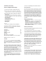
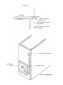
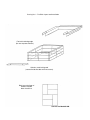
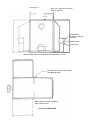
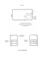
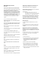
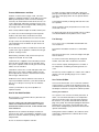
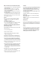
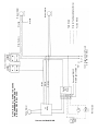
INSTALLATION and OPERATING
INSTRUCTIONS
SUMMERAIRE
GAMME SMO
SBB
INSTALLATION AND OWNER’S OPERATING INSTRUCTIONS
SBB WOOD/OIL COMBINATION FURNACE
READ AND UNDERSTAND THESE INSTRUCTIONS
BEFORE OPERATING YOUR SUMMERAIRE FURNACE.
SAVE THESE INSTRUCTIONS FOR REFERENCE
THIS FURNACE MUST BE INSTALLED AND SERVICED BY A QUALIFIED INSTALLER
AND WHERE REQUIRED BY LAW, A LICENCED TECHNICIAN.
SUMMERAIRE MFG.
PETERBOROUGH, ONTARIO
FOR SERVICE CALL:
NAME : __________________________
ADDRESS : ______________________
__________________________________
TELEPHONE : ____________________
Installation Instructions
In all cases, local building codes should be observed.
Furnace Is Shipped In Six Packages:
Duct Connection
1. Furnace heat exchanger, complete with fire door.
The return air duct connection should be tight, so that the
blower cannot draw air from he furnace room which can
interfere with the combustion air supply. A plenum chamber or an elbow type connection may be used. Sufficient
air flow must be provided for efficient operation. An opening into the furnace room should be made to the outdoors
if there is not sufficient air infiltration. The equipment has
to be installed in accordance with the standards of the
National Board of Fire Fire Underwriters. Authorities who
have jurisdiction should be consulted before installations
are made.
2. Blower section (can be mounted left or right hand)
complete with blower, miscellaneous parts bag, filters.
3. Burner with flame retention head and oil combustion
safety control;
Field wiring junction box with transformer, solid fuel
relay, blower wiring harness, burner cable and fan limit
control with support;
Belt and pulleys;
Solid fuel damper motor;
Thermostats for solid fuel and oil;
Smoke baffle tool;
Blower motor;
Draft regulator;
4,5, & 6
Three cartons containing a total of 30 firebricks.
Installation Of The Combination Furnace
Chimney and Flue Pipe
Clearance to Combustibles
Top plenum
Front Side Wood
One Side
Oil Burner rear side
Flue Pipe
Other Side
Base or Floor non-combustible
Duct work may be reduced to 2” at 72” from plenum
MBFU Standards Include:
Standards for the installation of oil burning equipment.
NBFU No. 31.
Standards for the installation of air conditioning, warm
air heating and ventilating system. NBFU No. 90.
Building code standards for the installation of heat-producing appliances, heating, ventilating, air conditioning,
blower and exhaust systems.
6”
48”
6”
24”
18”
24”
Caution: Flue Pipe to Controls - 12”
Location
Refer to C.S.A. B139 “CODE FOR INSTALLATION OF
OIL BURNER EQUIPMENT” for recommended installation
practices. Consider the following before placing the furnace;
The furnace should be centrally located in relation to the
outlet registers, with large warm air ducts, for improved
heat distribution during electrical power failures, when the
furnace has to work on the gravity principle.
The flue connection to the chimney should be short and
direct and consist of as few elbows as possible.
Sufficient space must be provided for access to the burner, the controls, and along one side and at the rear of the
unit to provide access to the filters and blower. See above
for required clearances.
To ensure an easy installation of the two part furnace,
prepare a cement pad size 50” X 45” at least 2” thick, as
level as possible. It makes alignment of the two parts
easier.
The chimney should be thoroughly inspected and cleaned
to ensure safe furnace operation.
It is very important that the chimney has an adequate
capacity and develops a good draft for proper combustion.
.03 to .05 inches WC at the flue connection of the furnace, and .01 to .03 inches draft over the fire. Maximum
chimney draft should never exceed - 0.03” WC since a
power failure could cause wood fire to burn out of control. Minimum inside chimney 64 sq. inches.
The flue pipe must be full size and not lighter than No. 24
gauge black iron pipe. The flue pipe connection should
be short and direct with as few elbows as possible and
should slope up toward chimney. Make certain the flue
pipe or thimble does not project into the chimney flue. All
sections of the flue pipe should be fastened with sheet
metal screws. Under no circumstances should the flue
pipe contain a hand-operated damper.
Warning: Do not mount flue pipe close to or in front of
limit and operating controls.
Draft Regulator:
The draft regulator may be located on either the vertical
or horizontal section of the flue pipe. The best location is
18” from the furnace flue outlet. The regulator must be
level (without leaning forward or backward) and the pivoting axis has to be horizontal. Follow instructions for
installation which is supplied with the Draft Regulator.
Thermostats:
How To Install Fire Brick: Drawing #2
Select a location which is representative of the average
house temperature, usually the living room. The thermostats should be mounted on an inside wall, never where
they will be subjected to drafts (warm or cold), above a
radio or television set, or where the sun’s rays or heat
from registers will affect them. See instructions supplied
with the thermostats.
1. Install 6 brick in floor of firebox (see layout)
2. Place bottom row of bricks (for fire box sides, front
and back), making sure bricks are in brick plate
support frame which is an integral part of the box.
3. Repeat second and third rows of brick.
4. Install stainless steel front brick guard using bolts
provided.
5. Install “U” shaped top brick guard, inserting open ends
of guard into loops provided on inside of door opening.
For masonary chimneys refer to C.S.A. B1398 (p. 83). For
All Fuel chimneys consult manufacturers’ tables.
Furnace Assembly: Drawing #4
Locate Heat Exchanger Section in desired area
Four location points for locating blower port are supplied
on left and right side of furnace section, burner end.
Cut desired side for blower to enter furnace section.
Place blower section against furnace section and attach
with screws.
Furnace must be assembled as per drawing and fan-limit
control location identical to drawing, casing screw holes
are provided for exact locations. See Drawing No. 1.
Note: Due to the taper design of firebox mortar is not
required.
Installation Tips
*Minimum Duct sizes
Model
SBB
Supply Air
8 X 24
Return Air
8 X 24
* The supply air extended plenum size should be the
same as “Minimum Square inches” shown in above
table for 8-10 feet from furnace, then gradually
reduced to the end of the duct system.
* Use a minimum pipe size of 6 inches in diameter in
runs and in no case smaller than 5 inches in diameter.
Wire according to wiring diagram.
How To Mount The Burner:
* Set blower C.F.M. to obtain 85°F temperature rise
through unit, when fired on oil.
The burner is flush mounted with three positioning bolts
on the front plate. Connect the burner conduit cable provided on the wiring harness - follow wiring diagram.
Check nozzle size, tightness and chamber alignment.
Set up burner to #1 Smoke.
Finally
Wiring The Furnace: Drawing #3
2. That installation is made in accordance with C.S.A.
Installation Standard B 139 or the National Building
Code or NBFU No. 31
Each furnace is supplied with the necessary wiring harness. Follow diagrams for wiring and correct location of
the controls included in these instructions.
All electrical equipment and wiring has to installed following the requirements of the Canadian or U.S. electrical
code as well as regulations of local authorities.
Solid Fuel Damper Control: Drawing #1
The thermostat for the solid fuel section activates the
damper control - which in turn moves the damper flap. It
is essential that the damper control is at all time in perfect working order.
Note: Adjust damper chain so that damper flap opens no
more than 1/2”.
When oil is used as fuel close all combustion air inlets to
solid fuel side of furnace. Excessive air decreases the oil
burner efficiency.
We stress that it is your obligation to see that:
1. Owner receives
A) “Owner’s Operating Instructions”
B) This set of Installation Instructions
3. Owner is fully instructed in operating furnace, and in
all procedures necessary to ensure its complete and
safe operation.
Drawing No. 1
Furnace Unit
Blower Unit
Fan & Limit Bracket
Fan & Limit
Hole location determined by
holes provided
Note: Do not attach “BX” Conduit
to warm air plenum
Damper motor and bracket
Secondary Air
Control
Open link in chain
Summeraire Model S.B.B.
Drawing No. 2 Fire Brick Layout and Installation
Fire brick retaining angle
(fits over top row of bricks)
Stainless steel brick guard
(secured inside fire door with two screws)
Brick layout for floor of
fire box chamber
Note: Install first
Summeraire Model S.B.B.
Drawing No. 3
Note: “BX” cable must not touch
warm air plenum
7 1/2”
R8225B Relay
for optional induced
draft only
Solid fuel relay
Junction box
Note: R8225B. Relay not required when damper motor is used
Fan and limit must be in this location.
(See drawing detail)
Blower cabinet may be installed on
either side of oil end
Summeraire Model S.B.B.
Drawing No. 4
15 5/8”
4”
14 1/4”
Cut out for blower on desired side
Corner points of cut-out are indicated
on both side panels
Damper motor
and bracket
Secondary
Air control
Secondary
Air control
Summeraire Model S.B.B.
Limited Warranty SBB 137
Trent Metals Limited warrants, on a limited basis, this furnace to be free from defects in manufacturing as follows:
1. Heat exchanger is warranted for a period of ten years
as detailed below.
2. Electric controls and outside casing (or jacket) are
warranted for a period of 1 year from the date of
installation.
3. Furnace incorporating any of the below listed features
shall carry a 1 year warranty from date of installation
on this equipment:
a) Combustion air fan (in place of draft damper
motor), blower fan and motor.
b) Grates and shaking mechanism
c) Firebrick, providing it is properly installed and
not damaged by careless firing habits.
Heat Exchanger Limited 10 Year Warranty
Cost to owner of replacement heat exchanger expressed
as a percentage of the retail price in effect at the time of
shipment of the replacement heat exchanger.
*First 5 years after date of original installation
0% (replaced no charge)
*From year 5 through year 6
20%
*From year 6 through year 7
40%
*From year 7 through year 8
50%
*From year 8 through year 9
60%
*From year 9 through year 10
80%
*From year 10 and over
100%
The foregoing warranty applies only where installation
has been made in full accordance with Federal and Local
Laws and Codes or ordinances applying to installation of
Wood (or Coal) burning furnaces, and failure is not
caused by abuse, or failure to observe proper operating
instructions and cleaning suggestions accompanying the
furnace; furnace has been fired with the proper type of
fuel and maintained in accordance with our instructions;
furnace has not been fired at an input in excess of its
rated or designed capacity; furnace has been installed
where standard or normal atmosphere prevails and the
unit is not subject to excessive humidity, dust conditions,
or chemical atmosphere of any type or any kind which
may cause accelerated metal corrosion.
Warranty extends only to the repair or replacement of
parts returned, freight prepaid, to us, and which prove
defective after inspection and testing by us. Any labour
involved in effecting repair or replacement is excluded
from the warranty and Trent Metals Limited assumes no
responsibility for consequential damages of any kind to
persons or property.
The following forms part of this warranty and is intended
to elaborate on specific points of our Limited Warranty:
- Warranty on above units will be denied as per the following:
1. Rusting of the secondary heat exchanger where obvious cause is improper cleaning; particularly at the end
of each heating season to prevent damp creosote
from attacking the heat exchanger material: or, a
defective or improperly installed humidifier leaking
water onto the heat exchanger.
2. Warpage and cracking above the top row of firebrick.
Note: Your furnace requires periodic cleaning throughout
the heating season. Also - at the end of the heating
season your furnace must be completely cleaned
including all areas of the secondary heat exchanger
where creosote residue may accumulate and attract
moisture from damp basement areas.
Remember the warranty of this unit specified it covers
the materials and workmanship of the unit. It does not
cover damage resulting from improper firing practices
or maintenance procedures.
Annual oil burner service is required.
Please follow our instructions and keep your unit operating at peak efficiency and keep the warranty on your
unit valid.
A heat exchanger replaced under warranty, assumes only
the remaining unexpired portion of the 10 year warranty
period, determined by the date of original installation.
This is the only warranty applicable to Summeraire
Furnace.
Model SBB
higher than room temperature. This will open the draft
damper allowing combustion air into the furnace.
Important: These Entire Instructions Must Be Read
Light the paper and close the fire charging door.
These entire instructions must be read to ensure the best
possible operation and safest use of the furnace.
Manufacturer’s recommendations and codes set down
by regulating authorities must be followed when installing
and operating furnace. ALL solid fuel burning furnaces
manufactured by Trent Metals Limited have been tested
for safety by the Canadian Standards Association
Laboratories and carry their Certificate of approval which
is recognized by Insurance Underwriters in Canada.
When the kindling is burning well put in some hardwood
and allow this to begin burning.
Owner’s Operating Instructions
Cautions
Do not use chemicals or fluids to start the fire.
Never fire with treated wood, or burn garbage, gasoline,
naptha or engine oil.
Never load wood in firebox higher than height of door sill.
Do not store combustibles within the minimum installation clearances.
Build a small intense fire at least once a day to reduce
creosote build up.
Add hardwood;
do not fill the firebox above the door sill
do not put in too much wood at one time during
initial start-up as you could smother the fire.
When fire has been established properly, set thermostat
to your desired setting. The thermostat controlling the
wood section should be set at 5° above the oil section
thermostat i.e. set oil section thermostat at 18° C (65°F)
and the wood section thermostat at 21°C (70°F).
Maintaining Fire
You will be required to maintain the fire in you home
manually.
The rate at which you have to charge your furnace will
vary with the size of house, type of wood and weather
conditions.
For safety keep fire charging door tightly closed.
When the fire in your furnace is not great enough to
properly heat your home the air circulation blower fan
will begin to come on more frequently. In a few days you
will establish the basic recharging period for your specific
application.
Do not adjust electrical control settings or blower pulley
arrangement.
It is better to build small intense fires than building large
smoldering fires as they reduce creosote build-up.
Operate the oil-side of unit once a week to ensure that it
will operate satisfactorily when needed.
Ash Removal
Clean chimney at least once a year, and inspect regularly
for creosote build up.
1. Allow fire to burn out.
Keep fire door closed and maintain all seals in good condition.
Make sure adequate combustion air is provided in furnace area.
DO NOT START WOOD FIRE IF OIL VAPOUR IS PRESENT.
Firing
Start the fire in your furnace with paper and kindling only.
Crumple a quantity of paper and place it on the “Floor”
of the fire box.
Randomly stack kindling on top of the paper allowing for
good combustion and air circulation.
Set your thermostat so that it is 7-10 degrees fahrenheit
2. Turn “Wood” thermostat to its lowest setting. This deactivates damper motor and allows damper door to
close (or de-activates combustion air fan if so
equipped).
3. Remove ash with clean-out tool provided.
4. Ash is to be disposed of in a steel container with a
tightly fitting lid and take out of doors immediately.
Other waste should not be placed in this container.
5. After ash removal return “Wood” thermostat to normal
setting and restart fire.
Furnace Maintenance and Care
Establish a routine for the storage of fuel, care of the
appliance, and firing techniques. Check daily for creosote
build up until experience shows how often cleaning is
necessary. Be aware that the hotter the fire, the less creosote is deposited, and weekly cleanings may be necessary in mild weather even though monthly cleanings may
be enough in the coldest months.
To charge or inspect solid fuel side with scrap wood,
push up smoke baffle and secure with smoke baffle tool,
over door in full open position. Do not operate with fire
door open.
Load solid fuel carefully as damage will result from careless operation.
Green wood burns poorly and produces less heat, more
smoke and creosote.
Have a clearly understood plan to handle a chimney fire.
To control creosote when burning wood in temperate
weather, stoke often with a small intense fire. Heat
requirements should determine the size of the wood fire.
For best results burn dry wood or hard coal. Do not burn
salt saturated driftwood, tar products, tires or trash.
Fuel Storage:
To help control creosote build up in furnace, burn well
seasoned hard wood, sun dried in an open area for at
least 12 months.
Do not allow any wood fire to smolder and cool the flue
system as this type of operation condenses the flue gas
products creating creosote.
When burning solid fuels, load your fire box up to the
height of the doorsill. Do not overfill.
Combustion air is supplied over the fire bed by air holes
in the fire door to help retard creosote formation in the
flue systems. Operate oil side one day per week to help
reduce creosote formation.
Clean filters at least once a month and replace with new
filters twice a year, unless conditions require more frequent replacement. If air flow is obstructed, the furnace
will run longer and waste fuel.
Oil blower motor as well as oil burner motor where oil
cups are provided at least twice a year with number 20
auto oil, 4 or 5 drops for each cup. Do not oil blower
bearings.
Contact your installer on any service problems or
replacement parts.
Do not store coal or combustible material within minimum clearances.
See minimum installation clearances to combustibles
label.
Store wood at least 8 feet, or twice the height of the pile
from the furnace.
To control creosote when burning wood in temperate
weather, stoke often with a small intense wood fire.
Do not load to capacity allowing the fire to smolder. A
low temperature, smoldering wood fire generates creosote.
The chimney must be capable of a - 0.05 in. W.C. draft at
all times. The safe operating range is from - 0.03 to 0.05 W.C.
How To Use Oil Side:
There are two thermostats, one to control the solid fuel
section and one to control the oil operating section. Set
solid fuel thermostat at its lowest setting to prevent solid
fuel damper control form cycling when oil burner operates.
Starting the oil burner:
How To Use Solid Fuel Side
Burn wood only - For maximum efficency burn well seasoned hard wood only.
DO NOT LOAD SOLID FUEL ABOVE FIREDOOR SILL
HEIGHT AS OVERHEATING WILL RESULT CAUSING
PREMATURE FURNACE FAILURE, A FIRE HAZARD AND
VOID WARRANTY.
Adjustment of the solid fuel air damper should never
exceed 1/2 inch open. A fixed limiter is installed on your
furnace to insure this maximum opening, and is not to be
tampered with.
Do not use chemical or liquids to start fire.
The operation of the oil burner is entirely automatic. To
start it, set room thermostat above room temperature.
Open shut-off valve at the oil storage tank, set burner
line switch to “on” position, bleed air with the bleeder
plug on the pump. Check the pump diagram attached to
the burner. As soon as pure oil (not foam) flows, shut
burner down and tighten plug. The burner will start and
operate automatically.
During extreme winter conditions, the oil burner can be
safely fired to supplement the solid fuel side for maximum comfort.
What to do when your oil furnace fails to start
Caution:
1. Raise your thermostat to 5°C (10°F) above the present
room temperature.
2. Make sure your burner switch is in “on” position.
3. Check the fuse box for blown fuses. Replace with
fuses of correct amperage.
4. Press the reset button on relay box, once only. Box is
located on burner.
5. If you hear a hum from the burner, and the motor has
not started, press the button on the oil burner motor.
If the warm air temperature exceeds 200°F without the oil
burner shutting down quickly open the warm air registers
and remove the blockage from the cold air return.
If test procedure did not end with the oil burner cutting
off, the limit control is defective.
If the limit control is defective immediately replace it with
one of the following:
If oil burner fails to start or runs only for a few seconds,
call a reputable serviceman.
Caution:
Never start oil burner under the following conditions:
1. If excess oil has accumulated in the combustion
chamber.
2. If furnace is full of vapour
3. If combustion chamber is very hot.
4. Do not throw lighted paper into combustion chamber
when motor is running but oil is not burning.
Procedure for checking the proper function of
the limit safety control
This procedure is CSA requirement and must be carried
out by service man:
1. Once each heating season.
2. After an extreme wood fire.
3. After the unit has been used in gravity conditions
(without electrical power).
The objective of this procedure is to temporarily over
heat the furnace to prove the limit control is operational.
a) Fire the furnace with oil. Wait until the circulating air
blower is running. Move drapes or furniture that may
be damages by heat away from the warm air registers.
b) Adjust the oil thermostat to its highest setting in order
to keep the burner operating.
c) Insert a duct thermometer to its highest warm air duct
at a point 12 inches downstream from the furnace
plenum. If the limit control is functioning correctly the
burner will shut off on high limit before the thermometer reads 200°F.
d) To begin the test, close all the warm air registers then
block the cold air returns with newspapers.
e) Watch the oil burner and note the temperature of the
warm air when the burner shuts down.
Honeywell - L4064J,11” insertion, limit setting 210°F,
positive stop.
White Rodgers - 5D51- 78, 11” insertion, limit setting
205°F, positive stop.
Warning - If the limit control is defective the furnace is
unsafe to operate.
Maintenance
Ashes never should be allowed to accumulate in the ash
pit so they in any way impede the flow of combustion air
to the fire. Excess ash accumulation can cause the fire to
go out.
Safety
Whenever a loading door is opened, it always should be
cracked slightly before full opening to allow oxygen to
enter and burn any combustible gases that are present.
Failure to do this could result in sudden ignition of the
unburned gases when the door is opened.
Emergency Procedure
Soot or Chimney Fire
1.
2.
3.
4.
Close damper door by unhooking chain.
Close fire door.
Do not remove flue pipe before fire is completely out.
Call the fire department.
Run-A-Way Fire
1.
2.
3.
4.
5.
Close damper door by unlocking chain.
Close fire door.
Close off all air from entering the firebox.
Fully open barometric damper to reduce draft.
Douse the fire with water to reduce the rate of combustion, if necessary.
Power Failure
1.
2.
3.
4.
5.
6.
7.
8.
9.
Close damper door by unhooking chain.
Close fire door.
Remove access door at ??????????????
Open all air registers fully and furnace room door to
give better air circulation.
Do not load fire box higher than 1/4 way up during
gravity firing.
The combustion air can now be supplied by opening
the secondary air control.
Open all warm air registers full open. Registers must
not be obstructed by furniture or drapes.
Continue to operate a small fire for duration of power
off period. Do not expect to maintain maximum comfort under no power conditions. To prevent injury do
not allow anyone who is unfamiliar with the operation
of the furnace attend it.
On return to normal power operation, return all altered
items to their normal operating positions.
For more information read labels and manual carefully.
NOTE: THE EXCESSIVE HEAT CAUSED BY AN
EXTREME FIRE MAY DAMAGE THE FURNACE SAFETY
CONTROLS. THEIR OPERATION SHOULD BE CHECKED
BEFORE THE FURNACE IS RETURNED TO SERVICE.
SEE: PROCEDURE FOR CHECKING PROPER FUNCTION OF THE LIMIT SAFETY CONTROL.
Specifications for SBB Furnace
B.T.U.
BONNET
96000
12000
124000
137000
*NOZZLE
.85 - 80°
SS/AR
1.00 - 80°
SS/AR
1.10 - 80°
SS/AR
1.20 - 80°
SS/AR
COMBUSTION
CHAMBER
SA-1
SA-1
SA-1
SA-1
AIR
FILTERS
2 - 12 X 24
2 - 12 X 24
2 - 12 X 24
2 - 12 X 24
EXT.
STATIC
.20”
.20”
.20”
.20”
C.F.M.
1025
1200
1325
1450
BLOWER
MAKE
DELHI
G12
TORIN
DELHI
BC
G12
1200 -5
TORIN
BC
1200 -5
DELHI
G12
TORIN
BC
1200 -5
DELHI
G12
TORIN
BC
1200 -5
BLOWER
PULLEY
8”
8”
8”
8”
MOTOR
PULLEY
3-1/4X 1/2
3-1/4X 1/2
3-1/4X 1/2
3-1/4X 1/2
TURNS
OPEN
4-1/2”
3-1/2”
3”
1”
MOTOR
H.P.
1/3
1/3
1/3
1/3
BELT
SIZE
45”
46”
46”
46”
BURNER
FAFC - 2
FAFC - 2
FAFC - 3
FAFC - 3
SHIPPING
WEIGHT
970
970
970
970
* Note:
All nozzles are semi solid spray pattern as specified on label
Nozzle shipped in unit is 1.20 - 80° - can be changed within specified ranges for desired output (see above)
WHEN FIRING AT .85G.P.H. (U.S.) OR 1.00 G.P.H. (U.S.) END CONE MUST BE CHANGED TO AFC - 2
Bonnet capacity rating given is for oil side
Maximum output of wood side is approximately 120,000 B.T.U.
“PULLY TURNS OPEN” shown above is a guide ONLY, UNIT IS TO BE ADJUSTED TO GIVE A 85°
TEMPERATURE RISE
Creosote - Important Woodburning Information
Creosote is the tar-like substance that forms on the heat
exchanger, flue pipe and chimney when burning wood.
Wood combustion is never complete, a visible sign is
smoke coming from your chimney.
Wood when freshly cut can contain as much as 50%
moisture, depending on the type. Air dried wood, when
under ideal conditions, will still contain approximately
20% moisture. The moisture, along with flue gas products, are vented outside by way of the flue pipe and
chimney. Flue gas products, when chilled, condense into
liquid creosote which may become a crystal (solid form)
as temperatures increase with heat requirements.
The heat control method on furnaces when burning
wood, is the size of the fuel charge along with the control
of combustion air, to increase or decrease the rate of
burning which governs the heat output.
To help prevent creosote in both grate and base burners,
burn dry seasoned wood, hard wood is more desirable
than soft wood. Govern your wood load with the heat
output required. Spring and fall require frequent small
charges. A small intense fire produces less creosote.
Short flue pipe runs help to keep the gases above the
dew point.
The interior chimney holds and retains heat longer resulting in less condensation than the exterior chimney.
A good draft produces a hotter fire and exhausts the flue
gases outside more rapidly at higher temperatures preventing condensation of flue products.
A combination furnace in need of cleaning, will have poor
draft creating a lazy fire and eventually, if ignored, may
smoke around the doors when the oil side is running with
wood fire. (Poor draft in a clean system can also produce
smoking around the door). This choked condition with
soot and creosote can only be relieved by cleaning the
entire system as frequent as necessary, if neglected it will
cause a chimney fire, which could result in property loss
and danger to lives of occupants.
Wood burning equipment must be vented into a factory
built OR masonary chimney. Chimneys must be built to
Building and Energy Board standards. Do not neglect
cleaning, or deliberately set your chimney on fire to burn
out the soot and creosote. If no damage is done to the
house, there will be damage to the chimney caused by
extreme heat. Not even the best chimneys are designed
for withstand repeated chimney fires.
FACTORY BUILT CHIMNEY MUST BE LABELLED THAT
IT COMPLIES TO UNDERWRITERS LABORATORIES OF
CANADA UCL - S629 - M.
Damper
Motor
Summeraire Model S.B.B.
Thermostats
Wood
Oil
Oil
Relay
Flame Sensor
Solid
Fuel
Relay
G. L1. N.
Wire Harness
120 V Supply 60 Cycle Fused
with 15A Time Delay
White Rogers 8A05A - 4
Honeywell R8405C
Orange
White
Black
NOTE: IN U.S.A. ALL WIRING TO BE DONE
IN ACCORDANCE WITH N.F.P.A. 70
NATIONAL ELECTRICAL CODE.
L4064R
Fan - Limit
Fan & Limit Control
L4064L
Fan - Limit
Burner Motor
Blower Motor
Factory Wired
Wire for Two Speed Option (Extra)
Field Wired
Ground
Orange