1
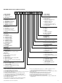
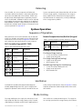
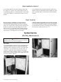
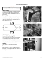
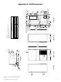
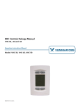
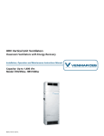
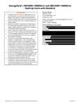
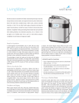
ERV Vertical Unit Ventilators Classroom Ventilators with Energy Recovery Installation, Operation and Maintenance Instructions Manual Capacity: 800 to 2,000 cfm Model: ERV1100w, ERV2000w with WSHP, Electric or Hydronic Heating ©2006 Venmar CES Inc. Table of Contents Nomenclature.......................................................................................................................................................................3 Safety Considerations..........................................................................................................................................................5 Specifications........................................................................................................................................................................5 Installation............................................................................................................................................................................6 Rough In.........................................................................................................................................................................6 Power..............................................................................................................................................................................6 Controls..........................................................................................................................................................................7 Balancing........................................................................................................................................................................8 System Operation.................................................................................................................................................................8 Sequence of Operation..................................................................................................................................................8 Ventilation......................................................................................................................................................................8 Mode Cooling.................................................................................................................................................................8 Recirculation Control.....................................................................................................................................................9 Frost Control...................................................................................................................................................................9 System Service......................................................................................................................................................................9 Monthly Maintenance...................................................................................................................................................9 Annual Maintenance...................................................................................................................................................10 Appendix A: Unit Dimensions...........................................................................................................................................11 Appendix B: Plenum Dimensions......................................................................................................................................13 Appendix C: Airflow Performance Data...........................................................................................................................15 Appendix D: Electrical Data...............................................................................................................................................19 Appendix E: Remote Occupant Interface.........................................................................................................................21 Appendix F: DDC Keypad Reference Guide......................................................................................................................22 Appendix G: Start-up and Troubleshooting.....................................................................................................................24 Appendix H: ERV1100w and ERV2000w Start-up Report................................................................................................26 Appendix I: ECM Motor CFM Adjustment Procedure......................................................................................................27 ©Venmar CES Inc. 2012. All rights reserved throughout the world. Illustrations cover the general appearance of Venmar CES products at the time of publication and Venmar CES reserves the right to make changes in design and construction at any time without notice. CES Group, LLC d/b/a Venmar CES furnishes equipment pursuant to its then-current Terms and Conditions of Sale and Limited Warranty, copies of which can be found under the Terms & Conditions of Sale and Warranty link at www.ces-group.com. Extended warranties, if any, shall be as offered and acknowledged in writing by Venmar CES. Manufacturer reserves the right to discontinue or change specifications or designs without notice or obligation. VCES-VUV-IOM-4B – ERV1100w & ERV2000w 2 Nomenclature ERV1100w Nomenclature (1,100 cfm nominal) 1 2 3 4 5 6 7 8 9 1. FROST CONTROL D – Recirc defrost1 E – Exhaust only2 V – VSD frost prevention3 N – Non-defrost 2. VOLTAGE/SPEED A – 120/1/60 – two-speed4 B – 208/120/1/60 – two-speed5 C – 230/120/1/60 – two-speed5 D – 208/3/60 – two-speed6 E – 230/3/60 – two-speed6 F – 460/3/60 – two-speed6 3. HEATING E – Electric heat H – Hot water M – High efficiency gas, modulating4/7 T – High efficiency gas, two-stage4/7 P – Proportional electric heat8 R – Hot gas reheat, on/off9/10 S – Hot gas reheat, modulating9/10 X – No heat 4. HEATING CAPACITY A – No heat Electric Options B – 2.5 kW (one-stage)7 C – 5.0 kW (one-stage)11 D – 5.0 kw (two-stage)7 P – 7.5 kW (one-stage)12 E – 7.5 kW (two-stage)7 Q – 10.0 kW (one-stage)12 F – 10.0 kW (two-stage)7 R – 12.5 kW (one-stage)12 Hot Water Options I – 50–70 MBH Hot Gas Reheat Options M – 30–40 MBH9 Gas Options J – 40 MBH7 K – 60 MBH7 5. GAS TYPE G – Natural gas L – Propane gas (CAN) P – Propane gas (US) X – Not applicable 6. COOLING C – Chilled water6/13 E – Chilled water with condensate pump6/13 Split System D – Dx coil only14 F – Dx coil with condensate pump14 Integrated System H – Copper, WSHP6 K – Copper with condensate pump, WSHP6 N – Cupro-nickel, WSHP6 P – Cupro-nickel with condensate pump, WSHP6 V – Condensate pump only, for gas heat X – No Cooling Notes: 1 When ordering recirc defrost, you must order an exhaust air damper. 2 An outside air damper must be selected. 3 Not available with two-stage compressors. 4 Not available with WSHP (water source heat pump) or electric heat options. 5 Requires a neutral wire with L1 and L2. 6 Not available with gas heating options. 7 Not available with three-phase voltage. 8 First stage is proportional and second stage (if applied) is fixed. 9 Only available with WSHP (water source heat pump) options. 10 Not available with controls option ‘D – Stand alone DDC controls’. 11 Not available with 460/3/60. 12 Not available with single-phase voltage: 208/120/1 and 230/120/1. VCES-VUV-IOM-4B – ERV1100w & ERV2000w 10 11 12 13 14 15 16 17 17. FREE COOLING F – Free cooling21 X – No free cooling 16. VALVES A – Basic valve kit9/19 B – Motorized on/off9/19 C – Motorized on/off, automatic flow rate control9/19 D – On/off zone, automatic flow rate control9/19 E – Automatic flow rate control9/19 F – No valves, flexible hose kit only9 X – Not applicable20 15. COOLING CAPACITY A – 2.0 ton B – 2.5 ton C – 3.0 ton D – 3.5 ton14 H – 2.5 ton, two-stage18 J – 3.0 ton, two-stage7/18 K – 3.5 ton, two-stage18 X – Not applicable 14. REFRIGERANT B – R410a X – Not applicable 13. ENERGY RECOVERY 1 – Aluminum wheel, no purge 12. EXTERNAL DISCONNECT N – Non-fused disconnect switch17 X – No disconnect switch 11. RETURN AIR DAMPER 1 – Motorized 2 – Spring return 10. EXHAUST AIR DAMPER 1 – Insulated motorized 2 – Insulated spring return 3 – No damper16 9. OUTSIDE AIR DAMPER 1 – Insulated motorized 2 – Insulated spring return 3 – Insulated modulating spring return 4 – No damper16 8. SUPPLY DISCHARGE T – Top plenum, no grille15 G – Top plenum, c/w grille15 D – Top plenum, c/w double deflection grille S – Silencer plenum, c/w grille15 X – No top plenum 7. CONTROLS D – Stand alone DDC controls R – Stand alone DDC controls with remote occupant interface X – No controls - field provided low voltage sequencing required 13 Chilled water coil available with 3.0 ton capacities only. 14 Dx ‘A’ coils available with 2.0, 2.5 and 3.0 ton – 13 SEER. Not available for 3.5 ton option. 15 Not available with gas and does not allow top access for electrical or pipe routing. 16 Non-defrost only. 17 Non-fused disconnect switch is field installed (remote mounted). 18 Available with R410a WSHP (water source heat pump). 19 Option includes: ball valve, blowdown valve, strainer and p/t port. 20 Not available with WSHP (water source heat pump). 21 Supply and exhaust airflows will be unbalanced. Free cooling is not available with gas heating or hot gas reheat. 3 ERV2000w Nomenclature (2,000 cfm nominal) 1 2 3 4 5 6 7 8 9 1. FROST CONTROL D – Recirc defrost1 E – Exhaust only2 V – VSD frost prevention3 N – Non-defrost 2. VOLTAGE/SPEED A – 120/1/60 – two-speed4 B – 208/120/1/60 – two-speed5 C – 230/120/1/30 – two-speed5 D – 208/3/60 – two-speed E – 230/3/60 – two-speed F – 460/3/60 – two-speed 3. HEATING E – Electric heat H – Hot water P – Proportional electric heat6 R – Hot gas reheat, on/off7/8 S – Hot gas reheat, modulating7/8 X – No heat 4. HEATING CAPACITY A – No heat Electric Options B – 2.5 kW (one-stage)9 C – 5.0 kW (one-stage)10 D – 5.0 kw (two-stage)9 P – 7.5 kW (one-stage)11 E – 7.5 kW (two-stage)9 Q – 10.0 kW (one-stage)11 F – 10.0 kW (two-stage)9 R – 12.5 kW (one-stage)11 Hot Water Options I – 60–90 MBH Hot Gas Reheat Options M – 40–50 MBH7 5. GAS TYPE X – Not applicable 6. COOLING C – Chilled water12 E – Chilled water with condensate pump12 Split System D – Dx coil only13 F – Dx coil with condensate pump13 Integrated System H – Copper, WSHP K – Copper with condensate pump, WSHP N – Cupro-nickel, WSHP P – Cupro-nickel with condensate pump, WSHP X – No Cooling 7. CONTROLS D – Stand alone DDC controls R – Stand alone DDC controls with remote occupant interface X – No controls - field provided low voltage sequencing required Notes: 1 When ordering recirc defrost, you must order an exhaust air damper. 2 An outside air damper must be selected. 3 Not available with two-stage compressors. 4 Not available with WSHP (water source heat pump) or electric heat options. 5 Requires a neutral wire L1 and L2. 6 First stage is proportional and second stage (if applied) is fixed. 7 Only available with WSHP (water source heat pump) options. 8 Not available with controls option ‘D – Stand alone DDC controls’. 9 Not available with three-phase voltage. 10 Not available with 460/3/60. 11 Not available with single-phase voltage: 208/120/1 and 230/120/1. 12 Chilled water coil available with 3.0 and 5.0 ton capacities. VCES-VUV-IOM-4B – ERV1100w & ERV2000w 10 11 12 13 14 15 16 17 17. FREE COOLING F – Free cooling20 X – No free cooling 16. VALVES A – Basic valve kit7/18 B – Motorized on/off7/18 C – Motorized on/off, automatic flow rate control7/18 D – On/off zone, automatic flow rate control7/18 E – Automatic flow rate control7/18 F – No valves, flexible hose kit only7 X – Not applicable19 15. COOLING CAPACITY C – 3.0 ton D – 3.5 ton13 E – 4.0 ton F – 5.0 ton J – 3.0 ton, two-stage9/17 K – 3.5 ton, two-stage17 M – 4.0 ton, two-stage17 X – Not applicable 14. REFRIGERANT B – R410a X – Not applicable 13. ENERGY RECOVERY 1 – Aluminum wheel, no purge 12. EXTERNAL DISCONNECT N – Non-fused disconnect switch16 X – No disconnect switch 11. RETURN AIR DAMPER 1 – Motorized 2 – Spring return 10. EXHAUST AIR DAMPER 1 – Insulated motorized 2 – Insulated spring return 3 – No damper15 9. OUTSIDE AIR DAMPER 1 – Insulated motorized 2 – Insulated spring return 3 – Insulated modulating spring return 4 – No damper15 8. SUPPLY DISCHARGE T – Top plenum, no grille14 G – Top plenum, c/w grille14 D – Top plenum, c/w double deflection grille S – Silencer plenum, c/w grille14 X – No top plenum 13 Dx ‘A’ coils available with 3.0 and 4.0 ton – 13 SEER. Not available for 3.5 ton option. Contact factory for information on 5.0 ton – 13 SEER coil. 14 Not available with gas and does not allow top access for electrical or pipe routing. 15 Non-defrost only. 16 Non-fused disconnect switch is field installed (remote mounted). 17 Available with R410a WSHP (water source heat pump) only. 18 Option includes: ball valve, blowdown valve, strainer and p/t port. 19 Not available with WSHP (water source heat pump). 20 Supply and exhaust airflows will be unbalanced. Free cooling not available with hot gas reheat. 4 Safety Considerations Warning, Caution and Important notes appear throughout this manual in specific and appropriate locations to alert Installing Contractors and maintenance or service personnel of potential safety hazards, possible equipment damage or to alert personnel of special procedures or instructions that must be followed as outlined below. ! WARNING Identifies an instruction which, if not followed, might cause serious personal injuries including possibility of death. CAUTION Identifies an instruction which, if not followed, might severely damage the unit, its components, the assembly or final installation. IMPORTANT Indicates supplementary information needed to fully complete an instruction or installation. Hazards may exist within this equipment because it contains electrical and powerful moving components. Only qualified service personnel should install or service this equipment. Untrained personnel can perform basic maintenance such as maintaining filters. Observe precautions marked in literature and on labels attached to unit. Follow all safety codes. ! WARNING Disconnect the main power switch to the unit before performing service or maintenance procedures. Electric shock can cause personal injury. Specifications The Vertical Unit Ventilator (VUV) series is one of the successful solutions to ventilation and indoor air quality problems from Venmar CES. This series consists of commercial heat and energy recovery ventilators with heating and/or cooling. Designed as appliances, they are ideally suited as complete classroom ventilators. With an upright configuration and small footprint, they require a minimum amount of space for installation. An optional top supply plenum allows for flexibility to suit various installations. The cabinet is well insulated and tightly sealed to provide quiet operation. • Electric Heat Option • • Case • • • • • 0.04” [1 mm] pre-finished steel Heavy gauge pre-finished steel Smooth texture Bone white finish Heavy gauge internal framework Unit Dimensions • See Appendix A for ERV1100w and ERV2000w. Plenum Dimension Drawings • • • • • Energy Recovery Module • Aluminum enthalpy wheel Filtration – Supply, Exhaust and Return Air • ERV1100w: 2” [51 mm] MEF disposable filter 12” x 24” [305 x 610 mm] standard outdoor air and 16” x 16” x 2” [406 x 406 x 51 mm] VCES-VUV-IOM-4B – ERV1100w & ERV2000w Aluminum hot water coil Control valve is field installed ERV1100w: 50,000 to 70,000 Btu/hr [14.6 to 20.5 kW] ERV2000w: 60,000 to 90,000 Btu/hr [17.5 to 26.3 kW] Proportional Electric Heat Option • See Appendix B for ERV1100w and ERV2000w. See Appendix C for ERV1100w and ERV2000w. Open coil electric resistance elements Two-stage operation: –– Stage one 2.5 to 5.0 kW – 208–230V, one-phase, 60 Hz 5.0 to 12.5 kW – 208–203V, three-phase, 60 Hz 7.5 to 12.5 kW – 460V, three-phase, 60 Hz –– Stage two 2.5 to 10.0 kW – 208–230V, one-phase, 60 Hz Hot Water Heating Option Airflow Performance Data • ERV2000w: 2” [51 mm] MEF disposable filter 12” x 24” [305 x 610 mm] standard outdoor air and 20” x 20” x 2” [508 x 508 x 51 mm] • Stage one –– 2.5 to 5.0 kW – 208–230V, one-phase, 60 Hz –– Proportional control 5.0 to 12.5 kW 208–230V, three-phase, 60 Hz 7.5 to 12.5 kW 460V, three-phase, 60 Hz Stage two –– 2.5 to 10.0 kW – 208–230V, one-phase, 60 Hz Hot Gas Reheat Option • • • Aluminum fin reheat coil ERV1100w: 30,000 to 40,000 Btu/hr [8.8 to 11.7 kW] ERV2000w: 40,000 to 50,000 Btu/hr [11.7 to 14.6 kW] 5 Installation Rough In The wallmount ventilator must be installed on a level base. Refer to Appendix A dimensions. Zero clearance is allowed between the bottom of the unit and any combustible material. Unit Installed without Top Plenum The supply air ducting must be connected to the supply collar and constructed so that there are no openings within 30” [762 mm] of the electric heating elements. Openings within 30” [762 mm] of the elements must be fitted with a permanent, non-removable protective screening. Zero clearance is required between the supply duct and any combustible material. A water trap is provided in the drain line to prevent back flow of sewer gases. The drain must be installed in an area in which it will not freeze. Water Supply Never operate the heat pump without water flowing through its water-to-refrigerant heat exchanger coil; doing so would cause severe damage to the unit. For proper water flow rates, refer to the unit Product Data Manual. Drainage Units equipped with air conditioning have a condensate line connected to the drain pan which drains out the back of the unit. Drain connections within the case are accessible by removing the access doors. Power ! WARNING Ensure that the power disconnect switch is off before connecting power to the unit or working with high voltage lines. A sealed strain relief clamp (supplied by the Installer) must be fitted into the case to accommodate a power line connection (see Appendix A for knock-out location). If a sealed clamp cannot be used, the hole must be sealed with silicone or an equivalent water/air-tight sealant. Power must be connected to the unit through a fused disconnect switch (factory supplied option, field installed). If the unit has a top supply plenum, a hole for the power must be field drilled in the plenum to accommodate the main power in. Terminals for line connection are located in the control box within the wallmount ventilator and are labeled as shown below. Connections are illustrated in Appendix E. Line connection to 120 VAC, 60 Hz is possible for units with hydronic heating or no heat options: Table 2: Line Connection to 120 VAC, 60 Hz for Hydronic Heating or No Heat L1 Hot N Neutral GND Ground Three-phase Line connection to 208, 230 or 460 VAC, three-phase, 60 Hz: Table 3: Line Connection to 208, 230 or 460 VAC, Threephase, 60 Hz L1 Hot L2 Hot L3 Hot GND Ground Single-phase Line connection to 208 or 230 VAC, single-phase, 60 Hz for electric heat units: Table 1: Line Connection to 208 or 230 VAC, Singlephase, 60 Hz for Electric Heat Units L1 Hot L2 Hot N Neutral GND Ground VCES-VUV-IOM-4B – ERV1100w & ERV2000w Electrical connections must be made in accordance with all applicable local codes and ordinances and with the current revision of the National Electric Code (ANSI/NFPA 70). For more information on electrical data, see Appendix D. 6 Controls The wall units contain a stand alone controls package consisting of either a Direct Digital Controller (DDC) system or an optional no controls package for field installation and controls. The DDC system allows the units to operate in either a stand alone capacity or in conjunction with numerous units via a field provided networking system. Stand Alone Controls (DDC) The mainframe for the stand alone DDC system is the programmable DSC-T305 controller/keypad. The DSC-T305 functions as a digital controller, LCD display for visual reference and as a 16-button keypad for user access to change operation parameters or to complete unit diagnostics. This controller is located within the unit and therefore can only be accessed by opening the front door of the unit. The DDC controller/keypad also may interface to expander modules (within the control box) to expand the input and output (IO) capabilities of the entire control system. Expander modules are deemed necessary based upon the requirements of the controls sequence. Heating icon Cooling icon Time of day Current temperature face option, a 10K thermistor is connected to the terminal strip to provide the controller with the current room temperature. Refer to Appendix E for the wiring diagram of both the remote occupant interface and room sensor. Refer to the Sequence of Operation section for general operation of the remote occupant interface (BacStat II) keypad. The remote occupant interface will allow a room occupant to adjust the room setpoint temperature and manually place the unit into occupancy override mode. By pressing the ‘On’ button, this mode can be obtained for durations of 60, 120 or 180 minutes. Pressing the ‘On’ button a fourth time will exit the occupancy override mode. Room Temperature Sensor Wiring Table 4: BacStat II Connections to Terminal Strip BacStat II Sensor 24 VAC GND + − Wired to Wired to Wired to Wired to Terminal Strip PWR 24V COM NET + NET − Without the BacStat II option, the room temperature is provided to the DDC controller via the wiring of a 10K thermistor. This thermistor must be connected to the terminal strip using a two-conductor shield cable, wiring one wire to the terminal ‘10K thermistor 1’ and the other to the terminal ‘10K thermistor 2’ (see Appendix E). No Controls – Field Provided Low Voltage (Sequencing Required) Status message Occupancy icon Supply fan level Figure 1: DSC-T305 controller display IMPORTANT For complete unit setup/configuration of the DDC controller system and outline of the troubleshooting guide, refer to the basic guide in Appendix F and the Sequence of Operation section for the DDC keypad operation. This guide is also placed within the unit for a more accurate description of the programmed parameters. The default four-digit ‘Pin’ password for access to the DDC menus is “4321”. Remote Occupant Interface (BacStat II) To provide remote monitoring and access of certain temperature setpoints and occupancy override features, a remote occupant interface option is available. This interface is referred to as the BacStat II and is connected to the DDC (DSC-T305) controller via the terminal strip within the unit. Without the remote occupant interVCES-VUV-IOM-4B – ERV1100w & ERV2000w A no controls package could be supplied to enable the end user to field supply and install a custom control system. In this application, the unit would contain the factory wiring and installation of basic electrical components such as damper relays, fan relays, electric heat contactors, low voltage transformer and standard terminals and connectors. General Wiring Auxiliary heating (non-heat pump or electric units), auxiliary cooling (non-heat pump units) and 24 VAC connections are available for field wiring on the unit terminal strip. Each of the auxiliary terminals provide 24 VAC during the applicable stage (ex. 24 VAC on auxiliary cooling terminal during cooling modes) while the 24 VAC terminals provide approximately 30 VA of power output. ! WARNING Installation and operation of field supplied controls must provide the correct designed operation criteria of the unit. Incorrect unit operation could void the warranty of certain unit components and/or result in complete unit failure. 7 Balancing Once installed, the unit must operate with balanced ventilation. Balanced ventilation is achieved by obtaining equal rates of outdoor and exhaust airflow. Airflow may be adjusted by balancing dampers (supplied by Installer) within the ductwork. Outdoor air volumes can be adjusted by changing the maximum open position on the opposed blade outdoor air damper. Supply airflow can be adjusted on both low and high speed using the ECM motor cfm adjustment procedure in Appendix H. Systems not operating with balanced airflow will not have effective energy recovery. Performance of the energy recovery module will be reduced and freezing may occur with cold outside air temperatures, resulting in blockage of the energy recovery module. System Operation Sequence of Operation Many parameters on the DDC controller may be adjusted to alter the durations and setpoints of the sequence of operation of the wall unit. Refer to Appendix F and the Controls section for more specific details of each parameter. DDC Controller/Keypad (DSC-T305) Remote Occupant Interface (BacStat II) Keypad Table 6: Remote Occupant Interface (BacStat II) Keypad Symbol Table 5: DDC Controller/Keypad (DSC-T305) Symbol Key Name Description Thermometer key Used to display the room setpoint. Clock key Used to display the time and date. Schedule key Used to display ‘On’ and ‘Off’ times. Occupancy key Used to initiate manual occupancy. Parameter keys Used to cycle through parameters. Increment keys Used to increase or decrease values. Key Name Description Increment keys Used to increase or decrease values. Heating/Cooling Operation First/Second Stage Heating • • 24 VAC on auxiliary heating terminal. Supply fan to low speed. First Stage Cooling (Free Cooling) • • Supply fan to high speed. Wheel rotation is off. Second Stage Cooling (Air Conditioning) • • • 24 VAC on auxiliary cooling terminal. Supply fan to high speed. Wheel rotation is on. Ventilation Ventilation time periods will be determined through the schedule programming of the DDC system. Using the DDC keypad, the operator is able to select the on and off times on a daily, weekly or monthly basis. Refer to Appendix F and the Sequence of Operation section for adjustment of the ventilation schedule. Mode Cooling First stage cooling puts the supply fan and exhaust fan to high speed and stops the energy recovery wheel. Second stage cooling is an option and calls for Dx cooling from eiVCES-VUV-IOM-4B – ERV1100w & ERV2000w ther a WSHP or a remote condensing unit. The supply fan runs on high speed and the energy recovery wheel rotates. 8 Recirculation Control In ventilation mode, the outside air damper is open and the supply air is a mixture with a percentage of return air. In recirculation mode, the ventilation damper is closed and 100% of the supply air is recirculated air from the return plenum. Units equipped with recirculation control are built with a damper mechanism controlling air flow through the intake duct. Ventilation mode is activated by the DDC controller schedule. Frost Control Recirculation and Exhaust Only Defrost VSD (Variable Speed Drive) Frost Prevention These two frost control strategies consist of a timer/controller that is activated by a thermistor which monitors the outside air temperature passing through the air intake. When the unit is in ventilation mode at defrost temperatures, the timer/controller activates frost control periodically to keep the enthalpy wheel free from frost. The VSD frost prevention strategy is achieved by modulating the rotational speed of the enthalpy wheel to maintain an exhaust air temperature of 33°F [1°C]. System Service Monthly Maintenance ! WARNING Disconnect the main power switch to the unit before performing service or maintenance procedures. Air Filters The standard medium efficiency filters are disposable and should be replaced monthly or as required by operating conditions. When installing a new filter, the airflow arrow should point in the direction of the enthalpy wheel. To remove the supply filter, open the bottom access door and pull out the filter as shown in Figure 2. To remove the exhaust filter, remove the bottom access door and pull out the filter as shown in Figure 3. Figure 3: Exhaust filter Figure 2: Supply filter VCES-VUV-IOM-4B – ERV1100w & ERV2000w 9 Annual Maintenance ! WARNING Disconnect the main power switch to the unit before performing service or maintenance procedures. Interior of Unit The inside of the unit should be vacuumed or wiped clean annually with a soft cloth and mild cleaning solution. Check the drain fittings (if equipped) to ensure they are draining freely. Enthalpy Wheel No cleaning of the enthalpy wheel is required. It is selfcleaning due to the opposing airflows. If the enthalpy wheel is cleaned, use low pressure air or a vacuum. Visually inspect the cassette brush seals and drive belt for proper operation. See Figure 4. Figure 5: Loosen wing nut to remove blower Rotor Brush.seal Figure 4: Brush seal Heaters/Air Conditioning Coils Figure 6: Disconnect electrical plugs Check the duct heaters, hot water coils and air conditioning coils for obstruction or buildup of dust. Check the manual reset button on your duct heaters (if the unit has electric heat). If the red buttons are released out, depress the red button to reset the switch. If this problem persists, call a qualified electrical technician for analysis. Dampers Check dampers for obstruction and cleanliness. Fans Blower wheels and fan housings should be checked for dust buildup. If excessive dust buildup exists, it will be necessary to remove the blower assembly to clean the dust out through the fan mouth. VCES-VUV-IOM-4B – ERV1100w & ERV2000w Figure 7: Removing the supply blower 10 VCES-VUV-IOM-4B – ERV1100w & ERV2000w Exhaust air Outdoor air LEFT VIEW B A 3.735” [95] 9.180” [233] C 8.753” [222] Supply air FRONT VIEW 41.300” [1,049] Return air TOP VIEW 2.250” [57] 3.456” [88] 12.000” [305] 5.534” [141] 75.851” [1,927] RIGHT VIEW 2.989” [76] 15.964” [405] 11.000” [279] D Free cooling bypass 67.964” [1,726] WSHP water line supply WSHP water 5.254” [133] line return Power connection Control wire connection Hot water coil supply/return CW/Dx condensate drain 30.500” [775] A B C D BACK VIEW 7.500” 7.500” [191] [191] 17.239” [438] EA OA 12.000” [305] Connection Sizes 2.0” [51] 1.0” [25] 1.0” [25] 0.75” [19] 14.000” [356] Access Opening Table Notes: Dimensions in [ ] are millimeters. Direction of airflow B 2.502” [64] 3.858” [98] 25.850” [657] 11.000” [279] A 32.000” [813] 2.670” [68] 2.904” [74] Appendix A: Unit Dimensions Figure A1: ERV1100w unit dimensions 11 Figure A2: ERV2000w unit dimensions VCES-VUV-IOM-4B – ERV1100w & ERV2000w 12 A D 3.645” [93] 16.125” [410] 75.747” [1,924] WSHP water line supply WSHP water 4.322” line return [110] 4.904” [125] 3.815” [97] B EA OA 12.000” [305] 7.500” [191] 18.646” [474] BACK VIEW 8.125” [206] 24.074” [611] Free cooling bypass 20.250” [514] TOP VIEW 2.250” [57] 12.250” 9.101” [311] [231] Outdoor air Exhaust air 2.502” [64] 3.934” [100] 11.000” [279] 34.350” [872] 25.899” [658] B A 32.000” [813] [74] 2.746” [70] 2.914” C 13.440” [341] 2.224” [56] LEFT VIEW A B C D FRONT VIEW 48.000” [1,219] Return air 84.249” [2,140] Connection Sizes 2.0” [51] 1.0” [25] 1.0” [25] 0.75” [19] Supply air Power connection Control wire connection Hot water coil supply/return CW/Dx condensate drain Access Opening Table Notes: Dimensions in [ ] are millimeters. Direction of airflow RIGHT VIEW 30.500” [775] Appendix B: Plenum Dimensions 1.25” [32] 2.25” [57] 26.75” [679] Control wire access Ø 1” [25] Electrical access Ø 2” [51] 8.75” [222] 27.00” [686] 30.50” [775] 41.30” [1,049] 23.75” [603] 17.00” [432] 11.75” [298] 1.25” [32] 3.00” [76] TOP VIEW 5.25” [133] Ø 1” [25] x 4 electrical/piping access holes 2.63” [67] FRONT VIEW RIGHT VIEW Note: Dimensions in [ ] are millimeters. Figure B1: ERV1100w standard plenum dimensions 1.25” [32] 2.25” [57] 30.50” [775] 41.30” [1,049] 26.75” [679] Control wire access Ø1” [25] Electrical access Ø 2” [51] 27.00” [686] 17.00” [432] 3.00” [76] 1.25” [32] TOP VIEW 5.25” [133] Ø 1” [25] x 4 electrical/piping access holes FRONT VIEW RIGHT VIEW Note: Dimensions in [ ] are millimeters. Figure B2: ERV1100w ducted plenum dimensions 8.75” [222] 30.50” [775] 41.30” [1,049] 23.75” [603] 11.75” [298] 7.74” [197] 15.96” [405] 3.38” [86] 3.74” [95] 25.00” [635] 11.03” [280] TOP VIEW FRONT VIEW RIGHT VIEW Note: Dimensions in [ ] are millimeters. Figure B3: ERV1100w silencer plenum dimensions VCES-VUV-IOM-4B – ERV1100w & ERV2000w 13 48.00” [1,219] 26.70” [678] 30.50” [775] 26.94” [684] 11.28” [287] Control wire access Ø 1” [25] Electrical access Ø 2” [51] 3.00” [76] 5.25” [133] TOP VIEW 1.25” [32] 2.20” [56] 1.25” [32] 17.00” [432] 3.21” [82] 4.05” [103] 19.26” [489] FRONT VIEW Ø 1” [25] x 4 electrical/piping access holes RIGHT VIEW Note: Dimensions in [ ] are millimeters. Figure B4: ERV2000w standard plenum dimensions 26.70” [678] 48.00” [1,219] 26.94” [684] 30.50” [775] 17.00” [432] Control wire access Ø 1” [25] Electrical access Ø 2” [51] 3.00” [76] 5.25” [133] TOP VIEW 1.25” [32] 1.25” [32] 2.20” [56] FRONT VIEW Ø 1” [25] x 4 electrical/piping access holes RIGHT VIEW Note: Dimensions in [ ] are millimeters. Figure B5: ERV2000w ducted plenum dimensions 2.43” [62] 48.00” [1,219] 7.74” [197] 16.28” [414] TOP VIEW 18.28” [464] 3.38” [86] 3.74” [95] 25.00” [635] 30.50” [775] 4.36” [111] 15.96” [405] 18.28” [464] FRONT VIEW RIGHT VIEW Note: Dimensions in [ ] are millimeters. Figure B6: ERV2000w silencer plenum dimensions VCES-VUV-IOM-4B – ERV1100w & ERV2000w 14 Appendix C: Airflow Performance Data ERV1100w on the right hand Y axis—Outside Air Percentage (% of Fully Open Supply Side Volume)—and run across to the Outside Air Curve (see #1 below). 50% equates to 42° open OA damper or 5.5 VDC for modulating damper actuator. 3. Find the new TA volume by running vertically from point #1 on the 42° open line to the Total Air Curve and then horizontally to the left hand Y axis (see #2 below). In this example, the TA is 95.5% of full open which is 95.5% x 900 = 860 cfm. 4. Find the corrected OA volume by multiplying the desired % OA volume (50%) by the new TA volume (860 cfm). Example: 50% x 860 = 430 cfm OA. 5. To find the damper setting for high speed cooling (1,200 cfm) the same procedure may be followed. In this example, 450/1,200 = 38% which is less than the minimum recommended amount of 41% (4 VDC or 24° open). This means that the damper should only be set to the minimum open position of 24° (or 4 VDC). The resultant TA amount will be 91% x 1,200 = 1,092 cfm with an OA amount of 41% x 1,092 = 448 cfm. Outdoor Air Damper Position Selection With the outdoor air (OA) and return air (RA) dampers fully open, the airflow values are given in the chart on the following page. OA volume is approximately 53% of total air (TA) with both dampers fully open. The following procedure shows how to determine the OA damper position to set the amount of OA available. Example • Desired TA for heating is 900 cfm. • Desired TA for cooling is 1,200 cfm. • Desired OA is 450 cfm. • Unit configuration is hydronic heat and Dx cooling. Since the worst case design is in the heating mode at 900 cfm TA, we need to start here. Procedure 1. If this OA volume is too high, calculate the desired percentage of OA volume to TA volume required. Example: You want 450 cfm OA and 900 cfm TA so 450/900 = 50% OA. 2. Determine the appropriate OA damper position to achieve the OA volume of 450 cfm by finding 50% Modulating Outdoor Air Damper System Response Minimum recommended open angle is 24° 24 100 OA DAMPER OPEN ANGLE (DEGREES OPEN) 30 36 42 48 60 42° open 58 #2 – 95.5% TOTAL AIR PERCENTAGE (% OF FULLY OPEN TOTAL AIR VOLUME) 59 57 96 56 55 94 54 53 92 52 #1 – 50% Total air curve 51 90 50 49 88 48 47 86 46 45 84 44 Outside air curve 43 82 OUTSIDE AIR PERCENTAGE (% OF FULLY OPEN SUPPLY SIDE VOLUME) 98 42 5.5 VDC 80 4.0 4.5 5.0 5.5 41 40 6.0 OA DAMPER VOLTAGE (VDC) Figure C1: ERV1100w airflow performance VCES-VUV-IOM-4B – ERV1100w & ERV2000w 15 Table C1: ERV1100w Airflow Performance Data Fan Speed External Static Pressure (in. w.g.) 0.0 TA 0.1 OA TA 0.2 OA TA 0.3 OA TA 0.4 OA TA 0.5 OA TA 0.6 OA TA OA Airflow High/Low Speed Setting Variable Between CFM Range Chilled Water Cooling with Electric Post-heat High 1,200 636 1,200 636 1,200 636 1,100 583 N/A N/A N/A N/A N/A N/A TA OA TA OA Low 900 477 900 477 900 477 900 477 N/A N/A N/A N/A N/A N/A 1,200 636 600 318 Chilled Water Cooling Only High 1,200 636 1,200 636 1,200 636 1,100 583 N/A N/A N/A N/A N/A N/A TA OA TA OA Low 900 477 900 477 900 477 900 477 N/A N/A N/A N/A N/A N/A 1,200 636 600 318 High 1,200 636 1,200 636 1,200 636 1,150 610 1,150 610 1,100 583 N/A N/A TA OA TA OA Low 900 477 900 477 900 477 900 477 900 477 900 477 N/A N/A 1,200 636 600 318 High 1,200 636 1,200 636 1,200 636 1,150 Low 900 477 900 477 900 477 900 Water Source Heat Pump or Dx Cooling with Electric Post-heat Water Source Heat Pump or Dx Cooling 610 1,150 610 1,100 583 N/A N/A TA OA TA OA 477 900 477 900 477 N/A N/A 1,200 636 600 318 Electric Heat Only High 1,200 636 1,200 636 1,200 636 1,200 636 1,200 636 1,200 636 1,200 636 TA OA TA OA Low 900 477 900 477 900 477 900 477 900 477 900 477 900 477 1,200 636 600 318 Chilled Water Cooling with Hot Water Post-heat High 1,200 636 1,150 610 1,150 610 1,100 583 N/A N/A N/A N/A N/A N/A TA OA TA OA Low 900 477 900 477 900 477 900 477 N/A N/A N/A N/A N/A N/A 1,100 583 600 318 Hot Water Heat Only High 1,200 636 1,200 636 1,200 636 1,150 610 1,150 610 1,100 583 N/A N/A TA OA TA OA Low 900 477 900 477 900 477 900 477 900 477 900 477 N/A N/A 1,200 636 600 318 High 1,200 636 1,200 636 1,200 636 1,100 583 N/A N/A N/A N/A N/A N/A TA OA TA OA Low 900 477 900 477 900 477 900 477 N/A N/A N/A N/A N/A N/A 1,200 636 600 318 High 1,200 636 1,200 636 1,200 636 1,175 623 1,150 610 1,125 596 1,100 583 TA OA TA OA Low 900 477 900 477 900 477 900 477 900 477 900 477 900 477 1,200 636 600 318 Water Source Heat Pump or Dx Cooling with Hot Water Post-heat or Hot Gas Reheat Gas Heat Outdoor air values are maximums. These volumes can be decreased using the outside air damper/maximum open setting. Airflow high/low valves may be set within the variable cfm range. Outdoor airflows are representative of actual air being delivered to the space. 50 cfm cross leakage has been subtracted from airflow measured at the outdoor air damper. All airflow measurements have been made in accordance with the Air Movement and Control Association (AMCA) 210 method of testing. VCES-VUV-IOM-4B – ERV1100w & ERV2000w 16 ERV2000w Outdoor Airflow Adjustment If the desired outside airflow is less than the value shown in the ERV2000w airflow performance data table (see Table C2), the amount of airflow can be reduced by partially closing the outside air inlet damper. Please note that the total airflow will be affected when adjusting the outside air damper. To determine the amount that the outside air damper must be closed, divide the desired flow by the rated outside airflow from Table C2. Example • 4 ton WSHP at 0.3 ESP and 500 cfm desired outside airflow. • From ERV2000w airflow performance data table: TA = 1,800 cfm and OA = 576 cfm. Procedure 1. Divide desired airflow by outside airflow rate: 500/576 = 0.87. 2. From outside air damper curve (below): 28° outside air damper setting. 3. New total airflow is: 1,800 x 0.94 = 1,692 cfm. 4. Airflow in unoccupied: 1,800 x 0.90 = 1,620 cfm. Outside Air Damper Curve 120 100 % AIR FLOW 80 60 40 20 0 0 20 40 60 80 100 OUTSIDE AIR DAMPER DEGREES OPEN LEGEND Outside airflow Total airflow Recommended range Figure C2: ERV2000w airflow performance VCES-VUV-IOM-4B – ERV1100w & ERV2000w 17 Table C2: ERV2000w Airflow Performance Data Chilled Water Cooling with Electric Post-heat Chilled Water Cooling Only Water Source Heat Pump or Dx Cooling with Electric Post-heat Water Source Heat Pump or Dx Cooling Electric Heat Only Chilled Water Cooling with Hot Water Post-heat Hot Water Heat Only Water Source Heat Pump or Dx Cooling with Hot Water Post-heat Water Source Heat Pump with Hot Gas Reheat Capacity 4 and 5 ton 3 and 3.5 ton Fan Speed External Static Pressure (in. w.g.) 0.0 TA 0.1 OA TA 0.2 OA TA 0.3 OA 0.4 TA OA 0.5 TA OA TA OA High 2,000 640 2,000 640 2,000 640 2,000 640 2,000 640 2,000 640 Low 1,800 576 1,800 576 1,800 576 1,800 576 1,800 576 1,800 576 High 1,600 512 1,600 512 1,600 512 1,600 512 1,600 512 1,600 512 Low 1,400 448 1,400 448 1,400 448 1,400 448 1,400 448 1,400 448 Airflow High/Low Speed Setting Variable Between CFM Range OA TA OA 2,000 640 TA 900 288 OA TA OA 1,600 512 TA 900 288 Outdoor air values are maximums. These volumes can be decreased using the outside air damper/maximum open setting. Airflow high/low valves may be set within the variable cfm range. For the 3 and 3.5 ton units, the return air (RA) damper is 30% open. Outdoor air (OA) can be reduced by partly closing the OA inlet damper. VCES-VUV-IOM-4B – ERV1100w & ERV2000w 18 Appendix D: Electrical Data Table D1: ERV1100w Blower Motors Full Load Amperage (FLA) HP ¼ (exhaust) ½ (supply – no gas) ¾ (supply with gas) Voltage 120/1/60 4.80 5.80 8.00 208/1/60 2.20 3.40 8.00** 230/1/60 2.20 3.40 8.0** 208/3/60 2.20* 3.40* 230/3/60 2.20* 3.40* 460/3/60 1.10* 1.20* 208/3/60 2.20* 3.40* 5.80* 230/3/60 2.20* 3.40* 5.80* 460/3/60 1.10* 1.20* 2.90* 208/3/60 6.95 13.90 20.84 27.79 34.74 230/3/60 6.28 12.57 18.85 25.13 31.41 460/3/60 3.14 6.28 9.42 12.57 15.71 208/3/60 9.30 10.40 15.50 20.70 19.60 22.90 230/3/60 9.30 10.40 15.50 20.70 19.60 22.90 460/3/60 5.00 6.30 7.10 6.90 10.70 10.70 Table D2: ERV2000w Blower Motors Full Load Amperage (FLA) HP ¼ (exhaust) ½ (1,200–1,600 CFM) 1 (2,000 CFM) Voltage 120/1/60 4.80 5.80 10.50 208/1/60 2.20 3.40 5.80 230/1/60 2.20 3.40 5.80 Table D3: ERV1100w and ERV2000w Heaters (FLA) kW Voltage 120/1/60 2.5 5.0 7.5 10.0 12.5 208/1/60 12.02 24.04 230/1/60 10.87 21.74 Table D4: ERV1100w and ERV2000w Compressors – One-stage, R410a (FLA) Tons Voltage 120/1/60 2.0 2.5 3.0 3.5 4.0 5.0 208/1/60 15.00 18.60 20.70 24.70 30.00 33.60 230/1/60 15.00 18.60 20.70 24.70 30.00 33.60 Table D5: ERV1100w and ERV2000w Compressors – Two-stage, R410a (FLA) Tons Type 2.0 2.5 3.0 3.5 4.0 Two-stage Two-stage Two-stage Two-stage Two-stage Voltage 208/230/3/60 7.20 12.90 15.80 15.60 18.10 208/230/1/60 13.00 17.00 20.00 23.60 32.10 460/3/60 3.90 6.40 6.90 7.10 8.50 Table D6: ERV1100w and ERV2000w Wheels and Controls (FLA) Voltage 120/1/60 2.73 208/1/60 2.73 230/1/60 2.73 208/3/60 1.58* 230/3/60 1.58* 460/3/60 0.71* The following notes apply to the above tables: All three-phase units have 208/230 VAC/1/60 fan motors * Primary side of the transformer. ** 120 VAC/1/60 motor used. *** Supply blower for units with gas heating only. Shaded areas indicate the voltage is not available. VCES-VUV-IOM-4B – ERV1100w & ERV2000w 19 Appendix E: Remote Occupant Interface The BacStat is connected to the unit using a four-conductor cable. Shielded cable should be used for the BacStat wiring and standard thermostat installation practices should be used. Avoid mounting the BacStat near any sources of heat or in places where airflow is restricted. The BacStat should be accessible to the occupant. CONTROL OUTPUTS HYDRONIC/STEAM VALVE + 24 VAC 2 − 24 VAC 3 W AUX. HEAT 4 Y AUX. COOL AUX. POWER The BacStat wires must run to the control terminal strip inside the unit. This terminal strip may have a wide variety of hardware and networking outputs (depending on the unit type and its configuration), but the BacStat connection is always clearly marked. The drawing below shows the BacStat wiring for a typical hydronic unit. CHILLED WATER VALVE 1 10K ROOM THERMISTOR 5 6 7 1 8 2 9 NET + BACNET MS/TP 10 NET − RS-485 10K ROOM THERMISTOR CONTROL OUTPUTS 1 + 24 VAC AUX. POWER 2 − 24 VAC 3 W AUX. HEAT 4 Y AUX. COOL −24 5 PWR 24V GND 6 COM + 7 NET + − 8 NET − 9 NET + BACNET MS/TP 10 NET − RS-485 CLASS 2 VOLTAGE Note: Use of 24 VAC circuit requires isolating contacts (ex. thermostat) to prevent interconnection of Class 2 outputs. BACSTAT II ROOM SENSOR + RS-485 − BACSTAT CONNECTION ONLY! Figure E2: Room sensor – 10K thermistor CLASS 2 VOLTAGE Note: Use of 24 VAC circuit requires isolating contacts (ex. thermostat) to prevent interconnection of Class 2 outputs. N Ground L2 L1 Figure E1: Remote occupant interface L1 L2 N High voltage terminals Notes: 1. Fused disconnect switch supplied by Installer. 2. 208–230 VAC/120/1/60 requires a neutral wire to be run with L1 and L2. 3. For 120/1/60 volt units, L2 is not required. Figure E3: Single-phase power supply wiring VCES-VUV-IOM-4B – ERV1100w & ERV2000w 20 Appendix F: DDC Keypad Reference Guide Unit Setup and Configuration Troubleshooting Quick Reference Guide Using the Keypad Controls Entering the Menu Mode Values are changed using the up and down arrow keys. To enter the menu mode, hold down the left and right arrow keys at the same time for a few seconds until the word ‘Pin’ appears on the display. Enter the ‘Pin’ number. At this point, the controller will enter the menu mode, displaying one of the three menus listed below. Adjusting Room Setpoint Press the ‘Thermometer’ key. The room setpoint will be displayed and may be altered using the up and down arrow keys (factory set at 72°F [22°C]). Pressing the ‘Thermometer’ key again will enter the selected setting(s). Adjusting Date and Time Press the ‘Clock’ key. Cycle through the time and date fields using the left and right arrow keys and adjust the values using the up and down arrow keys. Pressing the ‘Clock’ key again will enter the selected setting(s). Selecting Menu and Sub-menus Refer to Table F1. Use the number keys to select the appropriate menu and the left and right keys to alternate between the submenus. Selecting Individual Parameters and Settings Setting the Schedule Refer to Table F1. Press the ‘Schedule’ key. Cycle through the daily on and off times with the left and right arrow keys. Adjust the time with up and down arrow keys. To change the time increment (ex. hours to minutes) hold the ‘Occupied’ key down while using the up and down arrow keys to change the value. Pressing the ‘Schedule’ key again will enter the selected setting(s). Use the left and right arrow keys to cycle through the individual parameters and the up and down arrow keys to change the available settings. VCES-VUV-IOM-4B – ERV1100w & ERV2000w 21 Table F1: DDC Keypad Reference Guide Menu Manual Control Sub-menu Manual Mode Display – Man Mode Display – Ctrl Only one mode may Button ‘1’ on keypad be manually active at any time System Diagnostics Input Monitor Display – Diag Button ‘2’ on keypad System will continue to operate normally while in diagnostic mode System Configuration Display – Cfg Button ‘3’ on keypad Parameter Settings Active/inactive Off/stage 1/2/3/4 Off/stage 1/2/3 Off/stage 1/2/3/4 Off/stage 1/2/3 Value from sensor Value from sensor Value from sensor Display – IP Montr Value from sensor Value from sensor Value from sensor System Values Value from controller Value from controller 0, 1, 2, 3 0, 1, 2, 3, 4 Display – Sys Valu On/off On/off ID # 0°F to 70°F, set at 68°F Setpoint Adjustment Free cooling setpoint [−18°C to 21°C, set at 20°C] Unoccupied cooling Unoccupied heat 80°F, set at setpoint 76°F [27°C, set at 24°C] 0 to unoccupied cooling, set Unoccupied heating at 65°F [−18°C to unoccupied setpoint cooling, set at 18°C] OAD min position 0% to 100%, set at 50% Display – SP Adj Humidity setpoint 0% to 100% RH, set at 50% RH 40°F to 65°F, set at 50°F Discharge cooling setpoint [4°C to 18°C, set at 10°C] 50°F to 105°F, set at 90°F Discharge heating setpoint [10°C to 41°C, set at 32°C] −5°F to 50°F, set at 5°F** Defrost setpoint [−21°C to 10°C, set at −15°C] 0°F to 20°F, set at 4°F Controller Settings Heating prop band [−18°C to −7°C, set at −16°C] Heating reset rate 0 to 100%, set at 2% 0°F to 20°F, set at 4°F Cooling prop band [−18 to −7°C, set at −16°C] Cooling reset rate 0 to 100%, set at 2% Display – CO Setup Exit Menus Display – Exit Button ‘5’ on keypad VCES-VUV-IOM-4B – ERV1100w & ERV2000w Occupied ventilation Occupied heating Occupied cooling Unoccupied heating Unoccupied cooling OA temperature Mixed air temperature Coil leaving air temperature Discharge air temperature Exhaust air temperature Coax water temperature Cooling controller Heating controller Cooling stage Heating stage Defrost flag Free cooling flag Program ID Units Metric/US Dx cooling On/off Exit Yes/no Comments Unit will go into a standby mode while user is in manual control of outputs. * Display only – not adjustable. * Display only – not adjustable. * Display only – not adjustable. * Display only – not adjustable. * Display only – not adjustable. * Display only – not adjustable. * Display only – not adjustable. * Display only – not adjustable. * Display only – not adjustable. * Display only – not adjustable. * Display only – not adjustable. * Display only – not adjustable. * Display only – not adjustable. Modulating actuator only. Units with reheat only. ** 33°F for VSD frost prevention [1°C for VSD frost prevention]. 4°F [−16°C] = +/− 2°F 2% = 2% bias change/minute 4°F [−16°C] = +/− 2°F 2% = 2% bias change/minute * Recommend to power down the unit after changing this setting. Enables/disables Dx cooling. 22 Appendix G: Start-up and Troubleshooting Before powering the unit, check the following: • • • • • • High voltage is correct and matches the nameplate. Fuses, breakers and wire sizes are correct. Low voltage wiring is completed. Piping is completed and water system has been cleaned and flushed. Isolation valves are open and loop water control valves or loop pumps are wired. Service/access panels are in place. Unit Start-up 1. Set control above cooling setpoint. 2. Slowly reduce the control setting until both the compressor and water control valve are activated. Verify that the compressor is on and the water flow rate is correct. 3. After operating the unit for a few minutes, check that the unit is functioning properly by providing satisfactory cooling. 4. Adjust control below heating setpoint. 5. Slowly increase the control setting until both compressor and water control valve are activated. 6. After operating the unit for approximately ten minutes, check the supply air temperature to ensure the unit is providing satisfactory heating. 7. Check for vibrations, noise and water leaks. 8. Set system to maintain desired setpoint. 9. Instruct the owner/operator of correct control and system operation. Troubleshooting Should a major problem develop, refer to the following information for possible causes and corrective steps. Table G1: ERV1100w and ERV2000w Troubleshooting Problem Sufficient cooling or heating is not obtained. Cause Solution Restricted water flow. Check for restriction in water flow. Check refrigerant subcooling and superheat for low refrigerant charge. Low refrigerant charge. The reversing valve may be defective and creating a bypass of refrigerant. Improper installation of vibration absorbing material. Improper unit support. Check thermal expansion valve for possible restriction of refrigerant flow. Check compressor for loosened mounting bolts. Make sure compressor is floating free on its isolator mounts. Check for tubing contact with the compressor or other surfaces. Re-adjust by bending slightly. Check screws on all panels are in place and secured. Check for clattering or humming in the contactor or relays due to low voltage or a defective holding coil. Replace the defective component. Check for proper installation of vibration absorbing material under the unit. Unit must be fully supported, not just on corners. Incorrect discharge pressures. Check for abnormally high discharge pressures. Incorrect phasing. Check for proper phasing. Restricted refrigerant flow. Loosened mounting bolts. Tubing contact with compressor. Loose screws. Unit operation is noisy. If the unit will not cool, check the reversing valve coil. Low voltage or defective holding coil. VCES-VUV-IOM-4B – ERV1100w & ERV2000w 23 Table G1: ERV1100w and ERV2000w Troubleshooting Problem Cause The fuse may be open or the circuit breaker may be tripped. Supply voltage may be too low. Control system may be faulty. Wires may be loose or broken. The low pressure switch may have been tripped. Compressor will not run. The high pressure switch may have been tripped. The compressor overload protection may be open. Solution Check electrical circuits and motor windings for shorts or grounds. Investigate for possible overloading. Replace fuse or reset circuit breakers after fault is corrected. Check with a voltmeter. Check control for correct wiring and check the 24V transformer for proper voltage. Replace or tighten wires. Heating: •Lack of water flow. •Water too cold. •Loss of refrigerant. Cooling: •Insufficient supply airflow. •Loss of refrigerant. Heating: •Insufficient supply airflow. •Water too warm. Cooling: •Lack of water flow. If the compressor dome is extremely hot, the overload will not reset until it has cooled down. If the overload does not reset when cool, it may be defective. If so, replace compressor. The internal wiring of the compressor motor may be grounded to the compressor shell. Replace the compressor. The compressor winding may be open. Check continuity with an ohmmeter. If winding is open, replace the compressor. Check thermostat setting, calibration and wiring. VCES-VUV-IOM-4B – ERV1100w & ERV2000w 24 Appendix H: ERV1100w and ERV2000w Start-up Report Date:_____________________________________________ Site Reference:_____________________________________ Job Number:_______________________________________ Unit Number:______________________________________ Unit Type:_________________________________________ Room Number:____________________________________ Installer:_ _________________________________________ Representative:_____________________________________ Service Technician:__________________________________ Company:_________________________________________ Phone Number:____________________________________ Installation Check L2:______________________________________________ L3:______________________________________________ Running Current Heating L1:______________________________________________ L2:______________________________________________ L3:______________________________________________ Electric Heat Stage 1 Current L1:______________________________________________ L2:______________________________________________ L3:______________________________________________ Stage 2 Current __ Unit level. __ Unit bolted to floor or wall. __ Condensate drain correct. __ Wallsleeve correct. __ Wallsleeve insulated. __ Electrical connections tight. __ Damage to unit. Please describe:___________________ _________________________________________________ L1:______________________________________________ L2:______________________________________________ L3:______________________________________________ Mains Voltage Indoor Fan Refrigeration Size:______________________________________________ Type:_____________________________________________ FLA:______________________________________________ Fan Volts (L1 to M) Suction Pressure High:____________________________________________ Low:____________________________________________ Fan Current (L1) Cooling Mode:____________________________________ Heating Mode:____________________________________ Superheat High:____________________________________________ Low:____________________________________________ Cooling Mode:____________________________________ Heating Mode:____________________________________ L1:______________________________________________ L2:______________________________________________ L3:______________________________________________ Control Voltage:_ __________________________________ Cooling Mode:____________________________________ Heating Mode:____________________________________ Discharge Pressure Outdoor Fan Air Temperatures Size:______________________________________________ Type:_____________________________________________ FLA:______________________________________________ Fan Volts (L3 to M) Return Air Temperature High:____________________________________________ Low:____________________________________________ Fan Current (L3) Cooling Mode:____________________________________ Heating Mode:____________________________________ Outside Temperature High:____________________________________________ Low:____________________________________________ Cooling Mode:____________________________________ Heating Mode:____________________________________ Coil Temperature Compressor Size:______________________________________________ Type:_____________________________________________ RLA:______________________________________________ Running Current Cooling L1:______________________________________________ VCES-VUV-IOM-4B – ERV1100w & ERV2000w Cooling Mode:____________________________________ Heating Mode:____________________________________ Supply Air Temperature Cooling Mode:____________________________________ Heating Mode:____________________________________ Occupied Setpoint:_ ________________________________ Unoccupied Setpoint:_______________________________ Outstation Number:________________________________ 25 Appendix I: ECM Motor CFM Adjustment Procedure Step 1 Decrease CFM Using a DMM set to measure VDC, record all current values for each of the Flo points. Measurement is made between Flo Com and the respective Flo test point. Record these values under Factory Set. Refer to Figure I1 to locate test points. While measuring the Flo setting adjust the respective RP potientiometer counter-clockwise for that speed. A voltage decrease of 0.05 VDC will decrease the motor torque by one oz-ft. Increase CFM While measuring the Flo setting adjust the respective RP potientiometer clockwise for that speed. A voltage increase of 0.05 VDC will increase the motor torque by one oz-ft. A one oz-ft adjustment in motor torque will approximately increase/decrease the fan output by 25–50 cfm. Record the new values set for each Flo setting under Field Set values. Table I1: ECM Motor Adjustment Values Figure I1: ECM test points Step 2 If a voltage is present on Flo 0, that will be your low speed setting. If no voltage present on Flo 0 then Flo 1 is low speed. Each ascending Flo value corresponds to the next speed setting. VCES-VUV-IOM-4B – ERV1100w & ERV2000w Factory Set Measured Test Point Value Flo 0 Field Set Measured Test Point Value Flo 0 Flo 1 Flo 1 Flo 2 Flo 2 Flo 3 Flo 3 Flo 4 Flo 4 26 [email protected] www.venmarces.com Venmar CES Inc. has a policy of continuous improvement and reserves the right to change design and specifications without notice. ©2006 Venmar CES Inc. VCES-VUV-IOM-4B (PN 500000768) February 2014