1
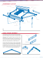
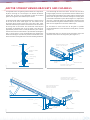
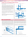
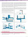
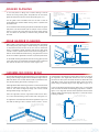
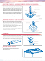
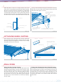
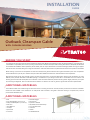
INSTALLATION
GUIDE
Outback Clearspan Gable
®
®
WITH COOLDEK ROOFING
BEFORE YOU START
It is important to check your Local Government Authority requirements before the installation of your new Stratco Outback® Clearspan Gable. It
is the builder’s responsibility to ensure any existing structure that an Outback Clearspan Gable is being attached to is adequately reinforced to
accommodate the additional loads imposed by the verandah, patio or carport. Read these instructions thoroughly before starting your project
and refer to them constantly during each stage of construction. Contact Stratco for advice if you do not have the necessary tools or information.
Before starting, lay out the main components in order of assembly on the ground and check them against the delivery note. The ‘Components’
section identifies each part of your Outback Clearspan Gable with Cooldek and shows the relative location of the components.
Mark out the overall area of your verandah, patio or carport and ensure that it is free from obstructions. Beam to wall connections can cause
difficulty if they coincide with door and window openings, so avoid these in your design. Ensure there is reasonable access for materials and
working space and consider the disposal of run-off water. Check the column and beam positions on the ground; roughly check they are square
by measuring the diagonals, then mark out the column locations. If columns are to be ‘in ground’, dig the holes to Stratco specifications.
ADDITIONAL MATERIALS
The Outback kit does not include fixings to attach the unit to an existing structure or concrete/masonry anchors for the column installation.
Other items not included in the standard kit are infill panels and accessories, box gutters and cover flashings. If required, they must be
purchased as additional items.
ADDITIONAL MATERIALS
• Drill
• Post Hole Digger
• Phillips Head Adaptors (5/16 & 3/8)
• Spanner or Ratchet
• Hex Head Adaptors (5/16 & 3/8)
• Rivet Gun
• Tape Measure
• Tin Snips
• Spirit Level
• Hack-Saw
• Silicone Gun
• Adjustable Construction Props
• Turn Up/Down Tool
• Concrete
• Ladder
• Extended Drill bit
COMPONENTS
COOLDEK
Insulated Roofing sheets
COLUMNS
Supports the beam
framework.
OUTBACK BEAMS
The beams are the frame to
support the roofing.
BEAM IN-LINE CONNECTORS
Joins beams flush to form a
continuous beam. Different
connections are available for
various angles and loadings.
BEAM FILLERS
Fills gap between interesting
beams. A notched version is
available where a column also
intersects.
BEAM TO BEAM BRACKET
Connects beams.
TEK SCREWS with
CYCLONE CAP AND
NEOPRENE WASHER
Used to fix insulted
deck into beams.
FOOTING PLATES
68 Outback Column
Reinforced Footing
Plate
WALL BRACKET
Fastens Outback beams
directly to a wall.
COOLDEK CLASSIC
COOLDEK CGI
POST BRACKET
Connects post
to beam
SPACERS
Are used to prevent the
150 attachment beam from
crushing.
POST CAP
FIlls gap between
the post and
beam
SCREWS AND RIVETS
Fastener types vary depending
upon the connection, ensure
the correct fixings are used.
DOWNPIPE
Funnels water from
the gutter to the
ground via the
outlet. Accessories
of mitres, shoes
and brackets are
available as optional
extras.
GUTTER STRAP & STOP END
RIDGE KNUCKLE
Slots inside the gable rafters to
form connection at the ridge.
GABLE BEAM BRACKET
Connects rafters to header
beam.
BEAM CAPPING
Fixed to top of the valley beam
to provide support for the
Cooldek.
68 OUTBACK COLUMN
WITH 50x50 SHS
REINFORCED POST
SHS POST CONNECTORS
gutter strap
Corner
Connector
Inline
Connector
gutte
RAFTERS
Gable rafters consist of
pre-cut 120 Outback
beam
RAFTER TO VALLEY BRACKET
Connects the rafter to the
valley beam.
receiving channel
receiving channel
SUSPENSION BRACKET
Replaces the
wall brackets
when the beam
is suspended
from the fascia
gutter riv
flashing
4.8mm sealed rivets
68 Outback Column
Footing Plate
4.8mm sealed rivets
SHS Column
Footing Plate
receiving channel
GUTTER
The gutter adjoins the roof to
catch water run off. Stop ends,
outlets and straps are available.
cutback flashing
front gutter
cutback flashing attach
panel under sheet
HEADER BEAM BRACKET
Connects end strut to header
beam on an infill gable.
RIDGE CAP
Covers the Cooldek at the gable
ridge.
BARGE CAP
The barge cap
covers the area
where the deck
finishes at the
portal frame.
HEADER FLASHING
Runs along the header beam
to neatly finish the base of the
infill panels.
END STRUT
The gable infill is
supported by the
end strut, which
consists of a section
of post.
22O END STRUT
PLATE
Secures the end
strut at the ridge
PANEL STRIPS
Decorative strips fixed to infill
panels.
INFILL PANEL
Cut to suit gable end frames.
RIDGE RAFTER BRACKET
Cut to suit gable end frames.
BEAM ENDCAP
Encloses ends of
beams.
ANGLED CUTBACK FLASHING
Flashing used to cover the deck
at the gutter end.
COMPONENT LAYOUT
angled back channel
ridge beam
gable frame
cooldek
valley beam
gutter
header beam
beam capping
valley beam
cutback flashing
GABLE FRAME ASSEMBLY
The first step when installing your Clearspan Ultimate with Cooldek is
to assemble the gable frame. This will determine your gable opening
which will be used when setting up the rest of the frame work.
open gable rafter
IMPORTANT: When assembling the gable frame ensure that the
double thickness portion of the beams is on top and the seam is on
the same side. The rafters are supplied pre-cut and drilled at the
ridge. There are two types of rafters used depending on whether a
header beam is being installed, these are shown in Figure 1.0.
Insert the ridge knuckle into the pre-cut rafters and screw together
infill gable rafter
(header beam)
using two 12x20 hex head self drilling screws through both sides of
each rafter and two 12x20 hex head self drilling screws through the
top (double flange side) of each rafter (figure 1.1). Make sure that
the two ends are flush at the connection, leaving no gaps. Measure
Figure 1.0
12 X 20 hex head
self drilling screws
ridge knuckle
the distance between rafter ends, O, to check valley beam spacing
(Figure 1.2). This will become the gable opening dimension.
12 X 20 hex head
self drilling screws
gable rafters
gable opening (O)
Figure 1.2
Figure 1.1
VALLEY BEAM ASSEMBLY
Before erecting any valley beams the capping needs to be fixed to
the top of the beams. The beam capping will support the Cooldek
when it is laid and the gable brackets will be attached to the beam
beam capping
beam
channel
capping. When fixing the beam capping ensure that the double
thickness of the beam is on top.
Fix the beam channel to the top of the valley beam using 12x20 hex
head self drilling screws at maximum 500mm centres and with two
fix beam capping to channel
using 3mm rivets each side at
500mm centres. Fix with two
rivets either side at the location
of a rafter.
locate the break
on the capping
in top groove of
valley beam
screws at the location of all rafters as shown in figure 2.0. Fix the
beam capping to the channel using 3mm rivets or 12x 20 hex head
screws each side at maximum 500mm centres and with two rivets
either side of the location of all rafters. Ensure the break is located
in the top groove (figure 2.0).
fix beam channel to top of valley
beam using 12 x 20 hex head self
drilling screws at 500mm centres.
Fix channel with two screws at the
location of a rafter.
valley beam
If attaching the valley beam to a header beam, notch the capping so
that it sits on top of the header beam as shown in figure 6.6.
Figure 2.0
ATTACHING ON SIDE TO HOUSE
A Stratco Clearspan attached on its side to a house is attached to
60x44x2.0 G450
galvanised channel
the existing eaves overhang at the fascia, or to an existing wall if
height permits.
The first objective in the construction is to fix a structural side beam
rafter
strengthening
bracket
along the fascia or wall, to which the Gable Unit is attached. Most
existing houses have not been designed for the attachment of portal
framed gables to their side, therefore additional strengthening of
the house rafters must be performed. In order to strengthen the
existing house rafters, the roof tiles or roof sheets need to be lifted
to expose the roof frame. Steel rafter brackets and channels are
then bolted along the house rafters.
M12 bolt
An attachment beam is bolted to the strengthening brackets at the
fascia. Once the attachment beam is secured to the house, the Gable
Unit can be erected and fastened to the beam.
timber rafter
The first step is to determine the number of rafters which need to
Figure 3.0
be strengthened and their location relative to the unit. You will have
to lift some roof tiles or roof sheets to discover the rafter positions
and spacings. The number of rafters which need to be strengthened
is determined by the builder, however spacing is recommended not
to exceed 1200mm.
Note: It is the builder’s responsibility to ensure the existing
rafters and fascia are adequately reinforced and strengthened to
accommodate any additional attached structure. The reinforcing
method must be approved by the appropriate council or engineer.
It is recommended an adjustable rafter strengthening bracket is used
in conjunction with an extension channel, as shown in figure 3.0.
The adjustable rafter strengthening bracket is shown in figure 3.1.
Adjustable Rafter
Strengthening Bracket
Figure 3.1
RAFTER STRENGTHENING BRACKETS AND CHANNELS
The adjustable rafter strengthening bracket allows for an adjustment
to be fed through the front of the fascia. The hole may need to be
of pitch in the range of 15 to 30 degrees. The distance the bracket
enlarged slightly if the M12 cup head bolts interfere with the fascia.
extends past the fascia is also adjustable to allow for standard
Insert the bracket through the fascia and fix with the channel to the
gutters or box gutters with a width of up to 200mm.
house rafter using M12 hex head bolts through the existing holes
In conjunction with rafter strengthening brackets a channel is fixed
piece so it is horizontal and has the appropriate extension past the
to the side of the house rafter (figure 3.0). The bottom end of
fascia to allow for fixing of the attachment beam. T piece connection
the channel will be located at the base of the house rafter. Holes
bolts are to be tightened to a minimum 50Nm torque.
in the bracket and further up the channel (Figure 4.3). Adjust the T
should be marked and pre-drilled in the channel to suit the location
of existing holes in the bracket. The channel will extend beyond
Fix the bracket as close to the base of the gutter as possible
the bracket so additional holes are to be drilled in the channel at
(recommended distance 10mm from lowest end of gutter), as shown
approximately 500mm centres. Initially the bracket T piece shall be
in figure 4.1.
fixed to the bracket arm with two M12 cup head bolts (hand tighten
only), a spring washer is to be located between the standard M12
The attachment beam is to be fixed to the end plate to ensure the
washer and nut (figure 4.0). Mark the position of the bracket on the
roof sheets drain into the existing house gutter (figure 4.1).
fascia and notch a rectangular hole in the fascia allowing the bracket
cooldek roof sheet
bracket arm
enough clearence for roof
sheets to run into house
guttet
t piece
tighten to 50Nm
torque
M12 washer
rafter
M12 spring
washer
M12 cup
head bolt
rafter
strengthening
bracket
M12 nut
attachment beam
fix bracket as close as possible
to the base of the gutter
Figure 4.0
we
b
ove
Figure 4.1
recommended channel extension
beyond birds mouth: 1900mm
recommended web overhang: 400mm
rha
ng
cha
nn
el
ex
ten
sio
n
rafter strengthening bracket
attached to rafter with
6 M12 hex head bolts
timber rafter
attachment beam fixed to
rafter bracket with two M12
bolts
channel
gutter
birds mouth
rafter
stud wall
eaves overhang
brick work
attachment beam
Figure 4.3
FIXING THE ATTACHMENT BEAM IN PLACE
After fixing all the brackets and channels, the attachment beam can
beam capping
now be fixed into place.
beam channel
Prop the attachment beam in position with the beam capping on top,
attachment beam
allows clearance between the Cooldek and the gutter. Fix to the end
rafter
strengthening
bracket
the beam will need to be located at a height on the bracket which
plates of the rafter bracket using two M12 bolts, with the bolt head
on the attachment beam side. Insert spacers to prevent the beam
from crushing, and bolt in position, using nuts and washers. To
double flange
spacer
M12 bolt
washer
nut
insert spacers drill 13mm holes through the attachment beam. Then
drill 16mm holes on the outside face only, but this time do not drill
all the way through. This will allow the spacer to slide in from the
outside and stop at the other side as shown in figure 5.
enlarged hole
(16mm this side only)
13mm hole
A cover flashing may be ordered as an additional option and custom
Figure 5.0
made to cover the exposed brackets and holes through the fascia.
Rivet flashings in place, figure 5.1 suggests a simplified flashing.
The attachment beam becomes the base for the attachment of the
house
gutter
Clearspan Gable unit.
attachment beam
Note: Do not over tighten bolts as this can lead to a visible
indentation due to the high gloss nature of the material. Refer to
figure 5.0 for fixing spacers.
rivet
fascia
strengthening
bracket
rivet
cover flashing
(optional)
Figure 5.1
END ATTACHED UNITS
If fixing a Clearspan Gable on its end to a wall, valley beams are
valley beam (beam cap on top) up into the wall bracket so the curved
fixed directly to the wall using beam to wall brackets. The rear gable
flange locate against the top flute of the beam. The valley beam is
frame will need to be offset from the wall to allow the appropriate
fastened to the wall bracket with two 12x20 hex head screws either
bracket fixing. Wall brackets are positioned either side of the gable
side in the pre-drilled holes while the opposite end is supported on
opening at the spacing determined in the section ‘Gable Frame
adjustable construction props. If required, additional hold down to
Assembly’. The folded section on the tabs of the bracket is located
the wall may be obtained by using tie down brackets, refer figure 6.1.
at the top (figure 6.0). The highest point of the wall bracket will be
15mm below the top of the beam. Mark the holes and drill using
A suspension bracket is used when a beam is suspended from
an 8mm masonry bit. Fasten the bracket to the wall with two M8
the fascia (figure 6.3). If fixing a Clearspan Gable on its end with
masonry anchors to a minimum 65mm embedment. Locate the first
suspension brackets, the brackets are to be positioned either side of
ridge beam
wall Bracket
beam capping
15mm
wall bracket
M10 bolt
two 12x20 self- drilling
screws on each side
valley beam
50 x 2.0mm tie down bracket
two M8 masonry anchors with
minimum embedment of 65mm
or
two 8mm diameter screwbolts with a
minimum embedment of 65mm
three M8 masonry anchors or
8mm diameter screwbolts
Recommended Bracket Length:
N1, 0 ≤ 5100mm : 1200mm length
N2, 0 ≤ 4200mm : 1200mm length
all else: 1800mm length
minimum edge distance of bolts and
screws is (10 x dia)
Figure 6.0
Figure 6.1
the gable opening. The gable rafter at the rear of the unit will need
beam is fixed to rafter strengthening brackets as detailed in the
to be set back sufficiently from the house fascia to accommodate
previous section. Beam to beam brackets are positioned at either
the house gutter and infill panel. Use silicone to seal behind the
side of the gable opening at the spacing determined in Section ‘Gable
suspension bracket and fascia. For steel fascia a minimum of three
Frame Assembly’. Fix beam to beam brackets to the attachment
M6 bolts with washers are fixed through the suspension bracket and
beam (header beam) with two 12x20 hex head screws so they clamp
fascia. For timber, three 12x25 type 17 screws are used to fix through
the beam filler to the beam (figure 6.6). The first valley beam is
the suspension bracket and timber. Refer figure 6.2 for fastener
fastened over the beam to beam bracket with two 12x20 hex head
locations. The first valley beam is slid into position and fastened
screws either side while the opposite end is supported on adjustable
using three 12x20 self drilling screws either side (figure 6.3), while
construction props.
the opposite end is supported on adjustable construction prop.
Note: It is the builder’s responsibility to ensure the existing
It is recommended extended fascia strengthening brackets and
rafters and fascia are adequately reinforced and strengthened to
reinforcing channels are fastened at a spacing not exceeding
accommodate any additional attached structure. The reinforcing
1200mm centres to fascia and rafters (figure 6.3). Brackets are also
method must be approved by the appropriate council or engineer.
recommended to the first rafter either side of the valley beams.
Secure brackets and channels to rafters with 12x25mm timber fixing
screws through pre-drilled holes and bolt through fascia with M10
bolts. If required, additional fascia reinforcement may be obtained
by securing RHS tubing behind the fascia, refer figure 6.4.
If fixing a Clearspan Gable on its end to an attachment beam (figure
6.5), elevated to the existing house gutter height, the attachment
extended fascia
strengthening bracket
(attach to rafter &
reinforcing channel
reinforcing
channel
fasteners; minimum
25mm spacing and
minimum 10mm from
any edge
Figure 6.2
in- fill panel
120 gable rafter
timber rafter
75 x 25 x 1.6 mm RHS
soaker
flashing
gutter
50 x 1.6mm
angle bracket
two 12 gauge
screws each leg
beam capping
soffit lining
fascia
M6 bolts and
washers
suspension
bracket
bolt through suspension bracket
fascia and RHS reinforcement
valley beam
12 x 20 hex head
self drilling screws
valley beam
Figure 6.3
beam capping
strengthening
bracket
attachment beam
beam to beam
bracket
two 12x20 hex head
self drilling screws
attachment
(header) beam
house
gutter
fascia
Figure 6.4
valley beam
beam filler
notched beam
capping
two 12x20 hex head self
drilling screws through
beam into bracket either
side
Figure 6.5
Figure 6.6
If any intermediate columns are required measure the valley beam
Support the second valley beam on adjustable construction props
section ‘68 Outback column’ or ‘SHS columns’. This can be done
gable frame has been attached.
COLUMN BRACKETS
marking where they meet. Fasten post brackets as explained in the
before the valley beams are fixed in place.
but do not fix to the wall, fascia or attachment beam until the front
BEAM TO BEAM CONNECTIONS
For units where rear and/or front header beams are required beam to beam brackets will be used. Place the bracket on the inside face of the
beam, aligning their curved flange with the top groove of the beam so that they clamp the beam fillers in place, fasten using two 12x20 hex
head screws (figure 7.0). Fasten the incoming beam either side with two 12x20 self drilling screws (figure 7.1).
curved flange
beam bracket fits inside
incoming beam
beam bracket
clamps over
beam filler
beam
beam
NOTE:
BEAM CAPPING IS NOT
SHOWN
beam filler
two 12x20 hex
head screws
two 12x20 hex head
screws either side
Figure 7.0
Figure 7.1
ATTACHING GABLE FRAME (WITHOUT HEADER BEAM)
The rafter to valley brackets are attached to the beam capping on
For a side attached unit support the second valley beam at the
valley beams using six 12x20 hex head screws (figure 8.0) at the
spacing determined in the section, ‘Gable Frame Assembly’ with
For an end attached unit attach the second valley beam into the wall
either side (figure 8.1).
appropriate locations.
or suspension bracket while using construction props to support the
adjustable construction props. The gable rafters can now be fixed
into the rafter to valley brackets with two 12x20 hex head screws
opposite end. The gable rafters can now be fixed into the rafter to
valley beam
capping
valley brackets with two 12x20 hex head screws either side (figure 8.1).
20
25
30
25
25
120
25
bracket position
inline with the
bottom edge of
the upper groove
150 VALLEY BEAM
WITH 22° RAFTER TO
VALLEY BRACKET
er
raft
bracket position
inline with the
bottom edge of
the upper groove
rafter to valley
bracket
two 12x20 hex head
screws either side
120 VALLEY BEAM
WITH 22° RAFTER TO
VALLEY BRACKET
valley beam
Figure 8.0
Figure 8.1
ATTACHING GABLE FRAME (WITH HEADER BEAM)
If the unit is being installed with header beam/s attach the beam to
attach rafter to bracket using
a minimum of 3 12x20 hex
head self drilling screws each
attach bracket using a
side
minimum of eight 12x20
hex head self drilling screws
the frame work using beam to beam brackets. If fixed at the rear to
an attachment beam this beam becomes the header beam.
Attach gable beam brackets to the header beam and capping using
a minimum of eight 12x20 hex head self drilling screws, refer figure
9.0. Rafters are supplied notched at the base to fit the gable beam
brackets. Rafters are fastened inside the gable beam brackets with
a minimum of three 12x20 hex head self drilling screws either side
beam
capping
rafter
header beam
as shown in figure 9.0.
gable beam
bracket
valley
beam
Figure 9.0
SOAKER FLASHING
If rear infill panels are being used, a soaker flashing is used to
conceal the existing house gutter, waterproof the rear end of the
gable and neatly finish the base of the infill panel (figure 10.0).
extended fascia
strengthening bracket
(attach to rafter & back
channel
infill panel
120 gable rafter
soaker
flashing
gutter
The rear gable frame and header beam are set back in order to
beam capping
accommodate the standard soaker flashing which is optional with
the Outback unit.
Fix the standard soaker flashing into position underneath the gutter.
Infill panels must be fixed with split tail soft pull rivets at 500mm
centres a minimum of 20mm above the pan of the soaker flashing.
This will reduce the possibility of moisture being absorbed into
soffit lining
valley beam
suspension
bracket
the sheet.
Figure 10.0
REAR HEADER FLASHING
When a gable is fixed at the rear to an attachment beam, elevated to
beam capping
infill panel
the existing house gutter height, a header flashing is used typically
header
flashing
in conjunction with the rear infill. In this case, the rear attachment
split tail
soft pull rivet
beam is considered a header and along with the rear gable frame
is fixed as close as possible (within 5mm) to the existing gutter in
house
gutter
order to accommodate the header flashing. The gable frame is fixed
on the rear header to gable beam brackets as previously described.
Fix the header flashing into position over the existing gutter lip with
rivets. Infill panels are located behind the header flashing and fixed
with split tail soft pull rivets at 500mm centres (figure 11.0).
fascia
strengthening
bracket
150 attachment
beam
valley beam
Figure 11.0
ASSEMBLING RIDGE BEAM
Fix the ridge rafter bracket at the ridge using six 12x20 hex head self
fastened either side through the ridge rafter bracket at the ends of
both ends of the unit. The base of the bracket is positioned 32mm
frame and run 68mm past the end of the beam at both ends of the
drilling screws through the gable frame and into the ridge knuckle at
from the base of the gable frames, refer figure 12.0.
If the ridge beam needs reinforcing, slide the c-section reinforcement
inside the ridge beam and fix with 12x20 hex head self drilling
screws at 500 centres through top flange and 1200mm centres
through bottom flange, refer figure 12.1.
Insert the ridge beam into the ridge rafter bracket and fix with a
12x 20 hex head self drilling screw on either side, refer figure 12.2.
the ridge beam. The angled back channel must rest on the gable
ridge beam. Fasten 12x20 hex head self drilling screws at 500mm
centres along the double flange of the ridge beam (Figure 12.3).
In the case of decking overhanging the gable frame, run the angled
back channel to the end of the overhanging ridge beam as shown in
figure 12.4. A ridge rafter bracket will be required at the front of the
ridge to support the overhanging ridge beam. A maximum 600mm
overhang is allowed.
12 x 20 hex head self
drilling screws at 500 cts
Fix angled back channel to both sides of the ridge beam using 12x20
hex head self drilling screws at 500mm centres, ensure a screw is
ridge rafter
bracket
6 12x 20 hex head screws
into gable frame and ridge
knuckle
c- section
reinforcement
outback beam
32mm
12 x 20 hex head self
drilling screws at 1200 cts
position bracket 32mm
from underside of
gable frame
Figure 12.0
Figure 12.1
12 x 20 hex head self drilling
screws at 500mm centres
along double flange of beam
ridge beam
angled back channel
ridge rafter
bracket
12 x 20 hex head
screw on both sides
into ridge beam
ridge beam
12 x 20 hex head screw
(at 500mm centres)
through angled back
channel into ridge beam
ridge rafter
bracket
screw through back
channel and ridge
rafter bracket
gable rafter
angled back channel
level with gable
rafter
gable rafter
Figure 12.2
Figure 12.3
600mm of ridge overhang
allowed. Run angled back
channel to the end of the
overhanging ridge beam
ridge rafter
bracket
Figure 12.4
68 OUTBACK COLUMNS
If using 68 Outback columns and fixing into the ground, dig the
holes to the specified size and place a brick in the bottom of the hole
(figure 13.1). At each post location, measure from the underside of
the beam to the top of the brick and cut the columns to length.
Check to ensure all columns are plumb.
Reinforcing the 68 Outback Column
If 50 x 50mm square hollow sections (SHS) have been supplied,
the fluted 68 Outback columns will need to be reinforced. Cut
two 12x35mm self drilling
screws per side
TOP
68 Outback column
50x50x3mm SHS
B
the 50mm SHS 75mm shorter than the column and slide into the
and fix using two 12 x 35 hex head screws per side, at both ends,
as detailed in figure 13.0.
68mm
column. Ensure the section is aligned with the base of the column
Post Brackets
Fasten post brackets to the underside of beams at the relevent
location with two 10x25 counter sunk self drilling screws either side.
Slide the top of the 68 Outback column over the post bracket until
it is flush with the underside of the valley beam. (Note: it may be
34mm
B
68mm
30mm
necessary to lift the fascia beam slightly to slide the column over the
post bracket). The unfluted faces of the column should be aligned
with each face of the post to beam bracket. Fasten the 68 Outback
column to the post bracket using two 12x20 hex head screws either
side as shown in figure 13.2.
Use construction props or bracing to hold columns in position, but
do not concrete in place at this stage.
section B- B
Figure 13.0
post cap
beam
bracket
width
column embedded
minimum 450mm
into concrete
10x25 counter sunk
self drilling screws
depth
12x20 hex
head screws
post bracket
notched beam filler
brick
12x20 hex
head screws
corbel
Figure 13.1
Figure 13.2
SHS COLUMNS
SHS corner
connector
If square hollow section (SHS) columns have been supplied, an
alternative post to beam connection method is used. Measure from
the underside of the beam to the top of the half brick and cut posts
beam bracket
SHS inline
connector
to this length at each post location. Screw the corner connector or
inline connector to the top of the SHS post with two 12x20 hex head
screws on either side of the column. Stand the post in position and
12 x 20
hex head screws
screw the connector to both the outside face and underside of the
beam with 12x20 hex head screws as shown in figure 14.0.
Use construction props or bracing to hold columns in position, but
12 x 20
hex head
screws
12 x 20
hex head
screws
do not concrete in place at this stage.
SHS post
SHS post
Figure 14.0
FOOTING PLATES - 68 OUTBACK COLUMNS
For non-reinforced 68 Outback Columns, two options of footing
plate are available if fixing posts to an existing concrete slab, please
familiarise yourself with the footing type being used before reading.
External Footing
If an external footing bracket is being used establish the column
lengths by measuring the distance from the underside of the fascia
beam to the concrete slab and deduct 20mm to allow for the depth
screws are located at least 15mm from the top of the upstand with
screws being a minimum 30mm apart.
Internal Footing
If an internal footing bracket is being used establish the column
lengths by measuring the distance from the underside of the fascia
beam to the concrete. Place the 5mm washer plate inside the footing
upstand and fix to the concrete with one M12x75 masonry anchors
of the footing bracket and cut the columns to length. Assemble the
(minimum 75mm concrete edge distance). Measure the distance of
the slots in the plate (figure 15.0). The upstand bracing must be
mark this position on the column. Drill a 13mm hole at this location
footing bracket and bracing into the bottom of the column, and
and bolt through the column and the upstand with one M12 bolt
footing bracket by sliding the legs of the footing upstand through
located between the legs of the upstand. Slide the assembled
fasten with two 12x20 hex head screws either side ensuring the top
the holes on the side of the footing upstand from the ground and
in the column. Slide the column over the internal footing upstand
(figure 15.1).
30mm (minimum)
M12 x 75 masonry
anchors or screw
bolts
two 12x20 hex
head screws either
side
upstand bracing
M12 bolt with
washer
5mm washer
plate required
footing plate
internal footing
upstand
footing upstand
minimum edge
distance
Figure 15.0
M12 x 75 masonry
anchor or screw bolt
minimum edge
distance
Figure 15.1
FOOTING PLATES - 68 REINFORCED OUTBACK COLUMNS
Measure from the underside of the beams to the top of the footing
50mm SHS
plate and cut the column to length. Refer section ‘68 Outback
Columns’ for reinforcement details. Slide the SHS reinforced footing
two 12 x 20mm hex
head screws through
both sides of column
bracket into the bottom of the column, and fasten with two 12x20
hex head screws on either side of the post. Locate the top screws
approximately 100mm from the base of the footing plate, and the
50mm SHS
footing plate
bottom screws 50mm from the base. This is shown in figure 16.0.
50mm
100mm
Slide the top of the column over the installed post bracket and
secure as previously indicated, refer section ‘68 Outback Columns’.
Use construction props or bracing to hold columns in position but
50mm SHS footing
plate fixed to slab
using four M10
masonry anchors
do not bolt to the concrete slab at this stage.
Figure 16.0
FOOTING PLATES - SHS COLUMNS
Measure from the underside of the beams to the top of the footing
plate and cut column to length. Slide the SHS column footing
bracket into the bottom of the column and fasten with two M10
two M10 bolts
four M12 chemical
anchors or equivalent
bolts through the post. This is shown in figure 17.0.
Fix corner or inline connectors to columns and fasten to beams as
previously indicated, refer section ‘SHS Columns’.
Use construction props or bracing to hold columns in position, but
do not bolt to the concrete slab at this stage
minimum edge
distance
minimum edge
distance
Figure 17.0
CAPPING
To prevent moisture from entering the beams and for aesthetics,
any beams with exposed ends require end caps to be fitted. Align
the end cap and push into the exposed beam end (figure 18.0). If
the postcap, align the two lugs with the two exposed holes of the
post bracket and push firmly (figure 18.1).
Outback columns are used, the postcaps can be fitted over the postbeam connection. Apply a small amount of silicone to the back of
post bracket
68 outback column
post cap
silicone into
bracket
beam end caps
Figure 18.0
Figure 18.1
FRAME WORK CHECK
Check the framework is square by checking the diagonal
measurements are equal.
Figure 19.0
FIXING THE PANELS
There are two types of profiles in the Cooldek range; Cooldek Classic
and Cooldek CGI, refer figure below. The same procedure is used
when fixing either option to the frame.
for Classic and every second crest for CGI into the beam capping
(and the flashing). If using 50mm Classic panels use 14x125mm
hex head self drilling screws (14 x 150mm for 75mm Classic panels,
14 x 110 for 50mm CGI panels and 14 x 125 for 75mm CGI panels)
COOLDEK CLASSIC
refer figure 20.3.
Pre-drill the crests of the ribs to provide clean holes for the seating
COOLDEK CGI
of neoprene washers. Use cyclone caps and neoprene washers for
all crest fixing. Do not over tighten screws. Fix side laps with 12x20
hex head screws with neoprene washer at approximately 1000mm
When attaching the Cooldek Sheeting, start from the rear on one
centres. Silicone to waterproof all rivets.
the angled back channel. Check the sheet is square against the
Beam Capping End - WITHOUT A SIDE GUTTER
the next sheet of decking over the previous sheets side lap and
for Classic and every second crest for CGI into the beam capping. If
side of the gable. Lift the first sheet into place and slide firmly into
receiving channel and the beam capping and fix into position. Lay
ensure that the slip joint of the two sheets has engaged, refer figure
20.0 and 20.1.
Note: The minimum Cooldek sheet length is 2.0m. If your design
requires sheets smaller than 2.0m they will be supplied at 2.0m and
If no side gutter is being installed fix the decking through each crest
using 50mm Classic panels use 14x125mm hex head self drilling
screws (14 x 150mm for 75mm Classic panels, 14 x 110 for 50mm
CGI panels and 14 x 125 for 75mm CGI panels), refer figure 20.4.
Pre-drill the crests of the ribs to provide clean holes for the seating
require cutting on site.
of neoprene washers. Use cyclone caps and neoprene washers for all
Ridge End
hex head screws with neoprene washer at approx 1000mm centres.
crest fixings. Do not over tighten screws. Fix side laps with 12 x 20
Sheeting is fastened to the angled back channel using 4.8mm sealed
rivets to the underside of the sheeting at maximum 200mm centres
and 12 x 20 hex head self drilling screws with neoprene washer
from the top into each crest for the Classic profile and every third
crest for CGI, refer figure 20.2.
Beam Capping End - WITH A SIDE GUTTER
When no side gutter is present a standard cutback flahsing will be
used to protect the foam. Cutback the foam and the bottom skin of
the insulated deck by 20mm. Position the cutback flashing as shown
in figure 20.5 and rivet to the panel at 500mm centres from both
sides. Silicone to waterproof all rivets.
If a side gutter is being attached to the unit an ‘Angled Cutback
side lap
12 x 20 hex head
screw
Flashing’ will need to be fixed to the ends of the sheeting. Cut back
the foam and the bottom skin of the insulted deck to the beam
capping, refer figure 20.3. Slide the angled cutback flashing between
the beam capping and the sheeting. Rivet the cutback flashing to the
top sheet at 1000mm centres and fix the decking through each crest
beam capping
CLASSIC
slip joint
12 x 20 hex head screw
side lap
beam
slip joint
CGI
Figure 20.1
12 x 20 hex head self drilling screw
with neoprene washer through
angled receiving channel
receiving channel
Figure 20.0
rivet angled
cutback flashing
to top sheet of
panel
14 gauge hex head self drilling
screw with cyclonic cap and
neoprene washer.
ridge beam
decking
angled cutback
flahsing
beam capping
angled cutback flashing
sits flush with beam
capping. Foam and
bottom skin of sheeting
needs to be removed to
here.
rivet through receiving channel
into decking at 200mm centres.
Figure 20.2
Figure 20.3
decking
14 gauge hex head self
drilling screw with cyclonic
cap and neoprene washer
rivet through top sheet
and cutback flashing
gable
rafter
beam
capping
cutback flashing sits
20mm back under top
sheet.
standard cutback
flashing
rivet through cutback
flashing into panel
Figure 20.4
Figure 20.5
SIDE GUTTER
Attach the stop ends to the side gutters with four rivets per stop end,
remove any swarf and waterproof with silicone. Lift the side gutter
and rivet it to the top sheet and angled cutback flashing at 1000mm
centres. Attach gutter straps to top sheet at maximum 1000mm
centres, refer figure 21.0. Note: The gutter profile will look different
if ‘Outback Gutter’ is used, see figure 21.2 for profile.
12 x 20 hex head self
drilling screw with
neoprene washer through
gutter strap into top sheet
When fixing gutters always ensure that the front face of the gutter
remains vertical and even. All screws to have neoprene washers.
Silicone to waterproof all rivets and any pan fixed screws.
Gutter Outlet
Position downpipe in line with column/s. Cut a hole in the base of
the gutter near the back chamfer. Insert the gutter outlet pop from
the inside of the gutter and rivet in place using 3mm rivets (figure
rivet through gutter,
cutback flashing and top
sheet
21.1), remove any swarf and waterproof with silicone.
rivet pop to gutter
gutter
gutter outlet
(downpipe pop)
gutter
notched
beam filler
Figure 21.2
downpipe
Figure 21.1
ed riv
ets
ch
m se
al
4.8m
anne
l
4.8m
m se
ack
cutb
d to eet
vete p sh
er ri and to
tt
u
g
g
hin
flas
tter
t gu
fron
ing
rece
iv
ng ch
aled
s
rivet
trap
er s
gutt
m
4.8m
eivi
CGI roofing sheets are being used then vermin proofing foam will
anne
l
ridge capping
gutt
e
r str
ap
The panels should be closed in order to protect against moisture
and vermin. Use foam vermin proofing supplied see figure 22.0. If
fix ridge cap to back
channel with rivets at
250mm centers
rivet
s
Position the ridge cap over the ridge beam and receiving channels
and rivet into the channels at 250mm centres, refer figure 22.1.
seal
ed
RIDGE CAPPING AND LOWER END CLOSURE
gutt
flas er rive
te
hin
g an d to c
u
d to
p sh tback
eet
gutt
er s
trap
rive
ted
to c
rest
Figure 21.0
decking
not be required.
gable rafter
foam vermin proofing
Figure 22.0
Figure 22.1
Gable infill panels are to be cut in triangle shapes to fit the end
spacings. Attach the header flashing to the underside of the header
End struts are fixed mid-span of the header to a header beam
infill panels. Refer figure 23.0 and 23.1.
frame. Panels can be painted to the desired colour before installing.
bracket at the base and an end strut plate at the ridge. Infill panels
beam with 12x20 hex head screws to neatly finish the base of the
fix to front of ridge with
two 12x20 hex head self
drilling screws
are fixed through the top groove of rafters and the lower groove of
the header beam with 8x35mm self embedding self drillingt screws
at 500mm centres. Panels are fixed to the end strut at the same
fix to strut with two
12x20 hex head self
drilling screws either
side
infill panel
header beam
12 x 20 hex head
self drilling screws
8x35 self embedding screws
header flashing
fix bracket to header wiith
two 12x20 hex head self
drilling screws
fix strut to bracket with two 12x20 hex
head self drilling screws on either sides
Figure 23.0
Figure 23.1
m se
aled
s
rivet
er s
gutt
trap
er
gutt
l
rivet barge cap to crest of
decking at 500mm centres
t
fron
anne
the barge at the apex of the gable for a neat finish. Trim the barge
at the gutter end to ensure a neat finish.
4.8m
mitre end
ng ch
barge cap
and rivet the top section to the deck as shown in figure 24.1. Mitre
eivi
Attach the barge cap by screwing the lower lip to the gable rafter
ack
cutb
d to eet
vete top sh
er ri
d
gutt ing an
h
flas
ATTACHING BARGE CAPPING
mitred barge cap
mitred barge cap
barge cap
gable rafter
fix barge cap to gable rafter
at front using 12x20 hex
head self drilling screws
trim barge cap
for neat finish
Figure 24.0
Figure 24.1
FINAL FIXING
Fixing into the Concrete Footing
Fixing onto Existing Concrete: External Footing
post hole with approximately 150mm of concrete and use a shovel
external footing plate, each plate must be fixed to the concrete. For
this process until the hole is full, continually checking the posts
column refer 25.3 and for an SHS column refer figure 25.2. The
from the column to ensure any water does not pool around the
70mm for M10 anchors, 75mm for M12 anchors and 120mm for
Thoroughly check the posts with a spirit level. When plumb, fill the
or pole to agitate the concrete to remove any air pockets. Repeat
as you go. The concrete must have a slight slope that runs away
base (figure 25.0). Once the concrete is set remove any temporary
bracing or props.
If the columns are to be fixed to an existing concrete slab with an
a 68 Outback Column refer figure 25.1, for a reinforced 68 Outback
minimum distances from an anchor hole to the concrete edge is
M16 anchors.
Fixing onto Existing Concrete: Internal Footing
Ensure the M12 bolt is tightened. Refer figure 25.4
Important Note
Do not allow soil to remain in permanent contact with the columns, as corrosion will
CONTACT
1300 165 165
result in the base of the column. Refer to the “Selection, Use and Maintenance of Stratco
Steel Products” brochure for complete details of the maintenance requirements.
Downpipes
Before attaching the downpipes, rivet the downpipe brackets to the column and bend the
flanges along the ‘break-line’ to accept the downpipe. Slide the downpipe over the gutter
outlet and rivet into position. Rivet the downpipe to the brackets. Weatherproof all the
fasteners with silicone.
concrete raised
up to column
column
M12x75 masonry
anchors or M12x75
screwbolts
Figure 25.0
footing plate
SHS column
four M12x75 masonry
anchors
Figure 25.1
footing plate
Figure 25.2
68 Reinforced Outback
Column
M10 masonry
anchors
footing plate
Figure 25.4
Figure 25.3
MAINTENANCE
Regular maintenance is essential to maintain the good looks of all Stratco steel products
and to ensure you receive the maximum life-span possible. Washing with clean water
must be frequent enough to prevent the accumulation of dust, salts, and pollutants
that may reduce the life of the product. Stratco steel products that are regularly washed
by rain require no additional maintenance. No Stratco steel structure or materials are
recommended for use over, or in close proximity, to swimming pools or spas. No material
that retains water (such as dirt or paving sand) should be placed against the columns.
Care must be taken when determining the location of Stratco steel products so that they
© Copyright April 2012
All brands and logos/images accompanied by ® or ™ are
trade marks of Stratco (Australia) Pty Limited.
www.stratco.com.au
are not placed in close contact with sources of pollution or environmental factors that
could affect the life of the steel. Refer to the ‘Selection, Use and Maintenance’ brochure
for more information.