1
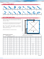
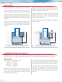
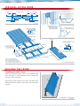
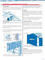
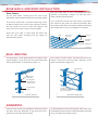
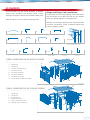
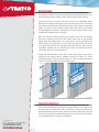
GUIDE
Gable Homesheds
™
FRAMEWORK
BEFORE YOU START
Council Approval
It is important to contact your local council before building your Stratco Gable Homeshed. You will have already
received a Council application form from Stratco, including an exploded view and a plan view of the proposed structure.
It is important to draw a plan view of your Homeshed on the second page of your “Council Copy” form. This view can
be copied from Figure 1 on page two. You must include the distances from the boundaries and existing buildings.
Before Starting
Confirm that all of the material listed on the delivery document has been supplied. Carefully read these instructions
to ensure you are familiar with all the steps involved. Ensure you have the correct tools and equipment for the job as
listed on page two.
TOOLS REQUIRED
Rivet Gun
Vice Grips
Step Ladder
Tape Measure
Spanner
Hacksaw
Pliers
Spirit Level
Permanent Marker
Caulking Gun
Silicone Sealant
Tin Snips
Gloves
String Line
5/16”
Power Drill
Hex Head Adaptor
SITE PREPARATION
“D” m
Determine the position of the Homeshed. If the ground is
F =82 mm (SC100)
F =108mm(SC150)
uneven or sloped, ensure that the slope does not exceed
more than 150mm.
Rear 100 or
150 mm C Section
If your Homeshed is being fixed onto a concrete slab refer
measurements are equal.
“C ” m
(Note the dimensions are listed in metres).
”m
Figure 1 and Table 1. Check that the corner to corner
“E
”m
Mark out the footing hole locations as specified in
“E
“B ” m
to the separate ‘Fixing to Concrete Slab’ instructions.
FRONT GABLE END
“A” m
Figure 1
Footing Hole Spacing
HOMESHED DETAILS
HOMESHED FOOTING HOLE DIMENSIONS
Size
Width x Length (m)
A
B
C
D
E
G1
3.159 x 6.207
2.801
6.087
3.045
-
6.701
G2
3.159 x 7.731
2.801
7.611
2.537
-
8.111
G3
3.159 x 9.255
2.801
9.135
3.045
-
9.555
G4
3.921 x 6.207
3.563
6.087
3.045
-
7.051
G5
3.921 x 7.731
3.563
7.611
2.537
-
8.404
G6
3.921 x 9.255
3.563
9.135
3.045
-
9.805
G7
5.445 x 6.207
5.087
6.087
3.045
2.568
7.933
G8
5.445 x 7.731
5.087
7.611
2.537
2.568
9.155
G9
5.445 x 9.255
5.087
9.135
3.045
2.568
10.456
G10
5.445 x 12.303
5.087
12.183
3.045
2.568
13.202
G11
6.207 x 6.207
5.849
6.087
3.045
2.949
8.442
G12
6.207 x 7.731
5.849
7.611
2.537
2.949
9.599
G13
6.207 x 9.255
5.849
9.135
3.045
2.949
10.847
G14
6.207 x 12.303
5.849
12.183
3.045
2.949
13.514
G15
6.969 x 6.207
6.611
6.087
3.045
3.330
8.987
G16
6.969 x 7.731
6.611
7.611
2.537
3.330
10.081
G17
6.969 x 9.255
6.611
9.135
3.045
3.330
11.276
G18
6.969 x 12.303
6.611
12.183
3.045
3.330
13.861
Table 1
FOOTINGS
Pad Footing Sizes (mm)
Eaves
Homeshed
Height
Width
(mm)
(mm)
3159
3921
2400
5445
6207
6969
3159
3921
2700
5445
6207
6969
3159
3921
3000
5445
6207
6969
N1 (W28)
Soil
Type
With Slab
N2 (W33)
Without Slab
With Slab
N3 (W41)
Without Slab
With Slab
Without Slab
Diameter
Depth
Diameter
Depth
Diameter
Depth
Diameter
Depth
Diameter
Depth
Diameter
A
375
600
375
700
375
600
450
700
450
800
600
Depth
900
B
375
450
375
550
375
450
375
600
375
450
450
700
C
375
450
375
550
375
450
375
550
375
450
375
550
A
375
600
375
700
375
700
450
800
450
800
600
800
900
B
375
450
375
550
375
450
375
700
375
500
450
C
375
450
375
550
375
450
375
550
375
450
375
600
A
375
700
450
700
375
700
450
900
600
800
600
1000
900
B
375
450
375
700
375
450
450
800
375
700
600
C
375
450
375
550
375
450
375
550
375
450
450
600
A
450
700
450
800
450
800
450
900
600
1100
600
1200
B
375
500
375
700
375
500
450
900
450
700
600
1000
C
375
450
375
550
375
450
375
600
375
500
450
700
A
450
800
450
900
600
800
600
1000
600
1000
600
1100
B
375
500
450
700
375
600
600
700
450
800
600
1100
C
375
450
375
550
375
450
375
600
375
500
450
800
A
375
600
375
700
375
600
450
800
450
800
600
800
B
375
450
375
550
375
450
375
600
375
450
450
700
C
375
450
375
550
375
450
375
550
375
450
375
550
A
375
600
375
700
375
700
450
800
600
700
600
1000
B
375
450
375
550
375
450
375
700
375
500
450
900
C
375
450
375
550
375
450
375
550
375
450
375
600
A
375
700
450
800
450
700
450
900
450
900
600
900
B
375
450
375
700
375
500
450
800
375
700
600
900
C
375
450
375
550
375
450
375
550
375
450
450
700
A
450
700
450
800
450
900
600
900
600
900
600
1000
1000
B
375
500
450
700
375
500
450
900
450
700
600
C
375
450
375
550
375
450
375
600
375
500
450
800
A
450
800
600
900
600
900
600
1100
600
1000
600
1200
B
375
700
450
800
375
700
450
800
450
900
600
1000
C
375
450
375
550
375
450
375
700
375
600
450
900
A
375
600
375
700
450
800
450
900
600
800
600
1000
700
B
375
450
375
550
375
450
375
600
375
500
450
C
375
450
375
550
375
450
375
550
375
450
375
550
A
375
700
450
700
450
800
600
800
600
800
600
1000
900
B
375
500
375
550
375
450
450
600
375
500
450
C
375
450
375
550
375
450
375
550
375
450
375
600
A
450
800
600
800
450
900
600
900
600
800
600
1000
B
375
500
450
700
375
500
450
800
450
700
600
1000
C
375
450
375
550
375
450
375
600
375
450
450
700
A
450
900
600
900
450
900
600
900
600
900
600
1100
B
375
600
450
700
375
600
450
900
450
800
600
1100
C
375
450
375
550
375
450
375
600
375
600
450
800
A
600
800
600
1000
600
800
600
1000
600
1100
750
1000
B
375
600
450
800
375
600
600
800
600
700
600
1200
C
375
450
375
550
375
450
375
700
375
700
450
900
Soil Type Code
A | Compact sand, gravel and sand
B | Fine sand, granular soil with conspicuous clay content
C | Stiff clay
Slabs to be minimum 100mm thick and reinforced with slab mesh.
Table 2
FOOTINGS
Dig the column holes as specified in Figure 2 and Table 2.
Before the concrete sets, score the top of the concrete
and place a brick in the hole as illustrated in Figure 2 and
If you are pouring a concrete slab, the slab must be a
Figure 3. Allow the concrete to set.
minimum of 100mm deep. Refer to Figure 3 and Table 2.
If you are installing a PA door, dig the door mullion
Use string line and a spirit level to ensure the holes are
footings at 300 wide x 300mm deep (refer to the
level with each other. Measure each hole depth to ensure
“Personal Access Door” section in this installation guide
the Homeshed will stand level when the walls are placed
for door mullion spacing).
in position.
Slab is to be minimum 100mm
Fill the base of each hole with approximately 200mm
thickness, reinforced
with SL72 fabric.
of concrete. This will ease settlement and make up the
distance between the base of the column and bottom of
Brick
Depth
Depth
250 min
500 max
350 min
Brick
400 max
Column
Column
100
the hole.
Diameter
Diameter
FOOTING SIZE WITHOUT CONCRETE SLAB
FOOTING SIZE WITH CONCRETE SLAB
Figure 2
Figure 3
CONSTRUCTING THE WALLS
Please Note: Girts will be supplied un-punched for Homesheds with non-standard lengths or non-standard bay spacings.
Please refer to Table 1 on page 2 of this installation guide for a list of standard Homeshed lengths and bay spacings.
Wall Frames
The number of columns for one wall:
As a general rule, the open side of each column will face
6.2m long
= 3 columns
the rear of the Homeshed, except for the front columns
7.7m long
= 4 columns
which face the front of the Homeshed. Refer to Figure 4.
9.3m long
= 4 columns
12.3m long = 5 columns
Please note that in standard Homesheds the columns
have been pre-punched at every wall girt/column
Depending on the length of your Homeshed, lay three,
connection, and at the rafter/eaves connection. At this
four, or five C-section columns on the ground making
stage, the columns must have the wall girt/column holes
sure the open side of each column is facing the correct
facing up.
way as illustrated in Figure 1.
CONSTRUCTING THE WALLS
Please Note: Girts will be supplied un-punched for Homesheds with non-standard lengths or non-standard bay spacings.
Please refer to Table 1 on page 2 of this installation guide for a list of standard Homeshed lengths and bay spacings.
Wall Girts
Pan fix the Stratco Superdek® wall sheets with 10x16mm
Similarly, in standard Homesheds the wall girts have
self drilling screws at every girt junction. The sheets are
been pre-punched at each wall girt/column connection.
laid with the short rib overlapping. Before fastening all
screws, run a string line from both ends of the wall panel
Place the wall girts across the columns and match the
through the centre of the girts to ensure all the screws
pre-punched holes. Refer to Figure 4.
will be fastened in line.
Fasten the top girt to the column with a high-tensile
The top of each wall sheet must be 5mm below the top
12x30mm flanged purlin bolt through each hole. The
wall girt. This will prevent any rubbing between the wall
top girt is fixed through the top pre-punched hole in the
and roof sheets.
columns.
Check the wall frame remains square as the wall sheets
Note: If a boxgutter is to be installed, the top wall girt
are fixed.
will be offset from the top of the column by 100mm.
(Refer to the boxgutter assembly instructions).
WALL SHEETS
Wall Sheeting
Under-lap
lip
10x16mm
self-drilling
screws
Ensure the framework is square and the diagonal
measurements are equal. Start laying the sheeting from
the back-end of the shed, to make sure the overlap seam
is not visible from the front of the shed. Ensure the top
5mm
edge of the wall sheets are aligned parallel with the top
edge of the top wall girts as illustrated in Fiqure 5.
Ensure the under-lap lip is aligned with the edge of the wall girts
Figure 5
ng
yi n
La ctio
re
Di
Bolt with one
M12x30mm
hex head bolt
Columns
5mm
Wall girts
HOMESHED WALLS
Figure 4
GUTTER INSTALLATION
Constructing the Gutters
Gutter Brackets
Rivet a left and right hand stop end to each length of
Crest fix the gutter brackets to the wall sheets at
gutter. Seal with silicone.
approximately 1000mm centres with pop rivets (refer to
Figure 7). Allow for a slight fall towards the downpipe
Cut a hole for each downpipe outlet and rivet the outlet
end so the water can flow freely.
into position (refer to Figure 6). Seal with silicone.
Once the gutter brackets have been installed, roll the
gutter bead onto the gutter bracket and clip the back of
the gutter into position.
Cut a hole and
rivet the outlet
into position.
Seal with silicone.
m
00m
y 10
atel
m
i
rox
App
Outlet
Pop rivet and silicone
the stop ends
Stop end
GUTTER INSTALLATION
Crest fix the
brackets with
pop rivets.
GUTTER
BRACKETS
Figure 6
Figure 7
PERSONAL ACCESS DOOR
Gutter Side PA Door
If you are installing a PA door, leave an 835mm gap
between the wall sheets. Fix the wall sheets on either side
of the proposed door location. It may be necessary to
rotate one of the wall sheets so the under-lap is aligned
with the door opening on both sides (refer to Figure
8). To avoid cutting, the sheets may need to be lapped
several times.
Once the wall sheets have been fixed, cut the middle and
bottom wall girts with a hacksaw. Do not cut the top wall girt.
Slide the door mullions into position so they cap the
middle and bottom wall girts. Notch and fix the door
mullions to the top girt with one 10x16mm self drilling
screw and one rivet (Figure 9).
Please Note: Do not use the PA door lintel as a mullion
spacing template. The PA door lintel is supplied longer to
allow for on site tolerance and must be cut to fit between
the door mullions.
Position and fix the door lintel to the door mullions with
two rivets. The door lintel should finish 2250mm from
the bottom of the wall sheets (refer to Figure 9).
Pan fix a wall sheet to the PA door frame with 10x16mm
screws. Fix the PA door side flashing with rivets at
600mm centres.
Determine which way the door will swing. The PA door
frame will be provided with two 100x75mm butt hinges
that are pre-welded in position. Fix the hinges to the door
mullion with 10x16mm wafer head screws.
If PA Door sheets require cutting, the excess sheeting can
be fixed above the PA Door in conjunction with a PA Door
gutter flashing. Alternatively, if a PA Door header flashing
is provided, rivet the PA Door header flashing to the door
mullions to flash the area above the door opening.
Gable End PA Door
For Homesheds greater than 2.4m high, the installation
of the PA Door mullions in the the gable end of the
Homeshed follow the same process as for the gutter
side, with the mullions being fixed to the top girt (under
the rafter).
If the PA Door is being installed in a Homeshed less than
2.4m high the top girt also needs to be cut as the PA Door
mullions are fixed to the rafter.
As gable end sheets are not rotated, two sheets will need
to be trimmed to allow for the PA Door opening (Figure
10). When cutting the second sheet try to cut along the
pan of the sheet to ensure a clean flat edge with no gaps.
A PA Door angle trimmer is supplied to flash the edge of
the second cut sheet (sheet 3 in Figure 10).
A PA Door gable end header flashing will be provided
and may require cutting. This flashing will cap the
bottom of the cut header sheets and act as a gutter
above the door opening.
PERSONAL ACCESS DOOR
Butt Hinge
Under-lap
Lip
Under-lap
Lip
PA Door Flashing
Door Frame
Wall Sheet Cut Line
2
Door Frame
Wall Girt
Wall Girt
Door Mullions
1
3
PA Door
Angle Trimmer
Figure 8
Cap bottom of the
header sheets with
the PA Door Header
Flashing provided.
Gable
Header
Sheets
PA Door Gable End
Header Flashing
Notch the end
to suit the top
wall girt.
Figure 10
PA door
7mm diameter
835mm
Pop rivet the PA door
header flashing to the
door mullions (only for
2.7 and 3m high garages).
45mm
m
0m
225
11mm diameter shaft
2210mm
Door lintel
Due to on site adjustments,
the door lintel will be provided
with an additional 30mm in length.
This will need to be trimmed back to
suit the space between the door mullions.
Wall girts
Door mullions
PA DOOR FRAME
Figure 9
BUILDING THE FRAME
Standing the Wall Frame
Stand the completed wall frame in the footing holes
(refer to Figure 11), and temporarily brace it. Make sure
the wall is level and square.
Repeat the previous steps for the other side wall frame.
Stand the two wall frames in the holes and brace them
securely.
STANDING THE WALL
Figure 11
BUILDING THE FRAME
Rafters
The rafters are bolted together on the ground using a
ridge bracket. Lay two rafters out, making sure there is
Rafter
Rafter
M12x30mm
high tensile
bolts
a left and a right rafter. The C-section opening on each
Eaves Bracket
rafter should open on the same side, with the purlin
holes on the flange pointing up.
Bolt the ridge bracket in place by lining up the rafter
and ridge bracket holes. Use an M12x30mm high tensile
flanged purlin bolt in each hole and tighten. To eliminate
any movement in the joint, screw four 12x20mm self
M12x30mm high
tensile bolts
drilling hex head screws through the ridge bracket and
into each rafter as displayed in Figure 13.
Eaves Bracket
Strengthening washer plate
Figure 12
Figure 13
Bolt the eaves bracket to each end of the rafter frames
with four M12x30mm high tensile flanged purlin bolts
(refer to Figure 12).
Roof Truss
Use a person on each end of the rafter frame to lift the
Alternatively the eaves brackets can be fastened to the
ends of the columns first. The ridge bracket and rafter
frame can then be lifted into position and bolted through
the eaves brackets.
frame into position. Bolt the eaves brackets to the column
ends with five M12x30 high tensile flanged purlin bolts
(refer to Figure 14).
Attach all the intermediate trusses first for stability, then
If strengthening washer plates are provided, bolt them
the front and rear trusses as previously described.
between the eaves brackets and the rafter/column joint,
as shown in Figure 13.
Wall frame
Ridge bracket
Lift the truss into place
Bolts
Screws
Figure 14
REAR WALLS AND ROOF INSTALLATION
End Columns
Bolt the rear wall girts to the end column with one
If your Homeshed is 5.4m or wider, attach the rear end
M12x30mm hex head bolt. The rear wall girts have been
column (100mm or 150mm C-section) to the rear truss
pre-punched at the end column /girt intersection.
with one M12x30mm hex head bolt as illustrated in
Purlins
Figure 15.
Please Note: Purlins will be supplied un-punched for
Homesheds with non-standard lengths or non-standard
bay spacings. Please refer to Table 1 on page 2 of this
installation guide for a list of standard Homeshed lengths
and bay spacings.
Ensure the Gable Homeshed is square. Position the roof
purlins across the rafters, match the pre-punched holes
(on standard Homesheds) and bolt into position.
End column
Figure 15
Rear Wall Girts
Check the frame is square and level before fixing the rear
wall girts.
Gable Wall Sheets
Before
fixing
the
gable
wall
sheets,
locate
the
raking flashing so it sits on the edge of each purlin,
following the roof line. Screw the raking flashing to
Fix three rear girt brackets (65x50x3mm) to both rear
columns with two 10x16mm self drilling screws as
illustrated in Figure 16.
each purlin with one 10x16mm self drilling screw.
Pan fix the gable wall sheets to the raking angle and
frame with 10x16mm self drilling screws as illustrated
Span three wall girts between each bracket and fix with
in Figure 17.
two 10x16mm self drilling screws through each flange
as shown in Figure 16.
Raking flashing
Girt
brackets
m
10m
Outside of
o
Homeshed
he
e
Inside of
Homeshed
Purlins
10mm
Girt
a
al
Portal
Column
n
End
Column
Rear wall sheets
GABLE WALL SHEETS
Figure 17
Girt
brackets
Footings
Check the alignment of the walls visually or with a string
line. Pour the concrete footings around the column base
and allow 24 hours before removing any braces. If you
End column
REAR WALL GIRTS
are fixing to a concrete slab, refer to the “Fixing to a
Concrete Slab” instructions.
Rear wall girts
Figure 16
REAR WALLS AND ROOF INSTALLATION
Roof Sheets
Turn the valley flute of every corrugated roof sheet
Fix the roof sheets, starting from one end of the
upwards as illustrated in Figure 18. This will aid in
Homeshed. Sheets should be laid into the prevailing wind.
water proofing the Homeshed.
Crest fix the sheets with 12x35mm self drilling screws
If it is necessary to walk over roof sheets, ensure that
or M6x50 timber/steel screws with neoprene washers.
you walk over the purlins to avoid any damage. Wear
Use five screws per sheet at each end support, and
flat, rubber soled shoes and walk flat footed, spreading
three screws per sheet at each internal support.
your weight over as many corrugations as possible.
Ensure the first sheet is square with the frame and
that the roof sheets overhang into the gutter by
approximately 50mm.
Valley
Turn up the
valley flute
Spanner
Corrugated
roof sheet
ROOF SHEETS
Figure 18
WALL BRACING
For Homesheds 5.4m or wider located in a N3 (W41) wind
These sheds will also require side wall end bays to be
speed category, a strap brace must be fixed around the
braced, at one end of the shed only. Bracing is to be
centre portal frames as illustrated in Figure 19.
fixed as illustrated in Figure 20.
End bay brace
Strap brace
30x0.8mm
Fix with three
10x16mm Self
drilling screws
Central protal
frame
STRAP BRACE
Fix with three
14x20mm self tapping
screws on each end
END BAY BRACING
Figure 19
Figure 20
DOWNPIPES
Slide the small end of one downpipe into the big end of
Fix the downpipe to the existing outlet using rivets, then
the other. Rivet the downpipe at the back, then use a
use downpipe straps to fix the downpipe against the wall
hacksaw to cut to the desired length.
using 10x16mm self drilling screws.
FLASHINGS
Screw the front and rear corner flashings at 600mm
Ridge and Barge Cap Installation
centres with 10x16mm self drilling screws. Corner
Fix the front and rear barge capping to the roof sheets.
flashings will require notching in line with the rafter pitch.
Lap the barges at the ridge line and trim the outside
piece to a vertical edge for a neat appearance.
Refer to Figures 21 and 22 for the flashing details.
Similarly, fix the ridge capping to the roof sheets with
12x35mm self drilling screws or M6x50 timber/steel
screws at 300mm centres.
1
2
3
Ridgecap
Bargecap
5
9
7
Standard Corner
10
PA Door Flashing
PA Door Mullion
Centre Column Cover
Internal Column Cover
6
Front Corner
4
Box Gutter
8
PA Back Corner
11
Filler Column Corner
12 | 13
PA Door Lintel (Z)
14
Tophat | Sliding Door
Header Beam
15
Sliding Door
Flashing
Roller Door Header
Flashing
2
1
GABLE HOMESHED WITH ROLLER DOORS
1 - Ridgecap
Box Gutter
(Optional Boundary Gutter)
15
7
2 - Bargecap
4 - Centre Column Cover
7 - PA Back Corner
9 - PA Door Flashing
10 - PA Door Mullion
11 - PA Door Lintel (Z)
15 - Roller Door Header Flashing
4
10
9
11
Figure 21
2
1
GABLE HOMESHED WITH SLIDING DOORS
1 - Ridgecap
2 - Bargecap
6
5 - Front Corner
6 - Standard Corner
14
8 - Filler Column Corner
14 - Sliding Door Flashing
5
8
Figure 22
WINDOWS
If installing a window, please note that the louvred window requires one
trimmed sheet and the sliding window requires two trimmed sheets.
During the process of fixing the wall sheets to the Homeshed frame
determine the location of the window. Fix the wall sheets prior to installing
the window according to the “Building the Frame” section of this installation
guide. The sheet/s in the location of the window will need to be trimmed
to accomodate the window, allowing for the base of the window to be
supported by and fixed into a wall girt.
Place the remaining sheets loosely into position and check the window
will fit the opening. Ensure the wall sheets either side of the window
tightly abutt the window frame so no gaps occur. Correct spacing of the
wall sheets is best achieved by ensuring the top edge of the wall sheets
are aligned parallel with the top edge of the top wall girt. Place the preassembled window into the opening and check for squareness before
continuing to lay the remaining sheets.
Install the window frame to the crest of the wall sheets using colour
10x16mm self drilling screws supplied. Ensure the screws are evenly
spaced around the remaining frame (Figure 23). Place a bead of silicone in
each corner of the window to prevent water entry.
Figure 23
MAINTENANCE
Your Stratco Homeshed will maintain its good looks for even longer with
a simple wash and wipe down with a soft broom. Stratco Homesheds are
produced from the highest quality materials and will provide many years of
service if the important recommendations set out in the Stratco ‘Selection,
Use and Maintenance’ brochure are followed.
© Copyright October 13