1
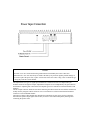
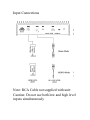
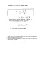
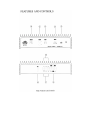
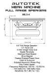
2Channel
High Performance Mobile Amplifier
Model : 100Xi
Owner’s Manual
Dear customer,
Selecting fine audio equipment, such as the unit you have just purchased, is only the beginning of your
musical enjoyment. Now is the time to consider how to maximize the fun and excitement your equipment
has to offer.
AUTOTEK and the Electronic Industry Associations Consumer Electronic Group want you to get the most
out of your equipment by playing it at a safe level, a level that lets the sound come through loud and clear
without annoying blaring distortion; most importantly, without affecting your sensitive hearing.
Sound can be deceiving. Over time your hearing "comfort level" adapts to higher volumes of sound, what
may have sounded "normal" can actually be too loud and harmful to your hearing. Guard against this by
setting your equipment at a safe level BEFORE your hearing adapts.
To establish a "safe level":
•
Start you volume control at a low setting.
•
Slowly increase the sound until you can hear it comfortably and clearly, and without distortion.
•
Once you have established a comfortable "sound level" make a not of this position and do not go above
this setting.
Taking a minute to do this will help to prevent hearing damage in the future. After all, we want you
listening for a lifetime.
Introduction
Your Autotek STREET MACHINE amplifier has been designed to give you very high performance, and
valuable features, at a reasonable price. Take the time to read over this brief set of instructions, and you
will get full enjoyment from your system.
Installation
The quality of the installation will affect system performance and reliability. You may wish to contact a
dealer or professional installer. The amplifier is generally mounted in the rear trunk area but can be
mounted in any convenient area such as beneath a seat. Please be sure to locate this unit where you have
reasonable air circulation and protection from any hazard with moisture. When considering the mounting
location you should minimize the length of the power supply and speaker leads. Minimizing both leads will
provide higher audio output from the system. It is important to ensure that the cooling fans or the heat sink
are not against a panel or a surface preventing air circulation. Mark the location from the mounting screw
holes by using the amplifier as a template. Drill #29 or 9/64" diameter holes at the marked locations and
firmly fasten the amplifier in place with the mounting screws supplied in the accessory kit. (Refer to Fig. 1)
Caution
Before drilling or cutting any holes investigate the layout of your automobile thoroughly; take care when
working near the gas lines or hydraulic lines and electrical wiring.
Warning
This power amplifier has a protection feature to prevent any damage from misuse or faulty conditions-excessive heat, short circuited speakers or overload. If the unit senses one of the above conditions, the
protection indicator will light and the system will shut down. To diagnose the problem turn all levels down,
all power off and check the installation for possible wiring mistakes or shorts. In the event the amplifier
shuts down due to excessive heat under adverse conditions simply allow time for the unit to cool down at
which time, the protection indicator will not light.
Fig. 1 Installation of Ampifier
Power Supply Connections
The +12VDC and ground wires should be heavy gauge standard copper wires with heavy insulation. The
wire gauge should be 4AWG for the AMX50.2 and AMX100.2 or larger. In addition, it has a 12V remote
control wire and it should be 14AWG-18AWG. It is preferable to have longer speaker wires and shorter
power supply wires to minimize power losses.
+12V Power
This wire is usually connected directly to the positive battery terminal. Ensure that the + power supply
wire. This connection must be completed by using spade lug with insulating sleeve.
Ground
This connection must be completed by using spade lug with insulation sleeve. This wire is the electrical
ground and must be fastened securely to the vehicle chassis. The best method is to use a threading sheet
metal screw since the threads cut into bare metal. Ensure that all paint coating or other insulation is
removed from around the hole area and using self tapping screw, securely affix the bare wire ends to the
vehicle chassis. Use as short a piece of cable as possible--use the same gauge as for the +12V.
Remote
Many radios or other music sources have an output terminal for connection of the remote turn-on of the
power amplifier. If a radio doesn't have a remote turn-on feature, then you can use the antenna relay wire
which activates the antenna motor. But you must take notice if the power antenna retracts when the tape
player is operating. In this case, you can't use the antenna relay wire to operate the remote turn-on.
Caution
First make +12V wire connection then the ground connection and finally the remote connection.
Furthermore the +12V wire must always be fused at the battery for protection against possible damage. If
you need to replace the power fuse, replace it with a fuse of the same value. Using a fuse of a different type
or rating may result in a serious hazard.
This amplifier has two types of signal input terminal. RCA connector for low level inputs and 5-pin
modular connector for high level inputs. Adjustment of input levels is accomplished by the gain control of
both channels. Adjusting this control allows the amplifier gain to be controlled to match and balance both
channels.
The RCA input connector should be used when connecting the radio/cassette line out and this connection is
usually made by using RCA-RCA connector wires. LCH connector is used for LEFT channel and RCH
connector is used for RIGHT channel.
The high level input of this amplifier has unearthed low impedance circuitry and is used to connect the
radio/cassette speaker output signals. Ensure that you observe each channel and polarity marking when
connecting the speaker wires.
Input Connections
Note: RCA Cable not supplied with unit:
Caution: Do not use both low and high level
inputs simultaneously
•
•
•
•
•
The amplifier can be used in the STEREO and MONO mode as shown in Fig. 4, Fig 5.
The speaker wires should be connected to the speaker terminal on amplifier.
Notice that most speakers have a polarity marking such as "=" or a dot on speaker terminals and these
markings denote the positive terminals of the speaker and are used as a guide to phase the speakers.
Improper phasing causes a loss of bass response.
When used in the MONO mode the speaker wires should be connected to the output terminals of the
amplifier as shown. (Ref. To Fig. 6)
Do not use less than 4 ohm in the mono mode.
When operating 4-speaker system, the impedance of the speaker is an important factor. Do not use
speakers in parallel for less than a 2 ohm load per channel in the stereo mode.
Caution
Be careful not to connect speaker(-) to the ground or chassis.
1.
2.
3.
4.
5.
6.
7.
8.
9.
RCA Low Level Input Jacks
It allows 1/2CH inputs to be connected to the amplifier us9ing RCA plugs.
Input Level Control
It allows for the adjustment of the gain of both channel so as to match the output level of the source.
X-over switch
a) Low position: Allows for the control of the low pass frequency 80Hz.
b) Flat position: Allows for full range pass through.
c) High position: Allows for the control of the high pass frequency 80Hz.
Hi Level input connector
Connect the radio's speaker output to the high level inputs connector. Do not use both lo9w and high
level input at the same time. Be sure not to confuse high level input with speaker outputs. Incorrect
connections may damage the amplifier or your source (High level input is based on common ground
signal.)
* High Input Connector
White: L-CH(+) Gray: R-CH(+) Black: Chassis Ground
Power indicator
It indicates amplifier has turn on signal.
Fuse
It protects both the amplifier and the automobile electrical system from fault conditions. Use a standard
automotive fuse, 100Xi: 15A
Power connection
Connects +12VDC power wire from the battery and also connects ground wire from a suitable ground
point on the chassis.
Remote connection
Connects the control wire which allows the amplifier to be turned on and off by the radio cassette
player.
Speaker Terminal
It allows the connection of speakers to the amplifier.
SPECIFICATIONS
STREET MACHINE
100Xi
*Audio Power output per Channel,
*both channels driven at 14.4VDC.
- 4 Ohms 1kHz, THD 0.05%
35W x 2
- 4 Ohms Bridged, THD 0.2%
80Watts
* Signal to Noise Ratio
>90dB
* Frequency Response, 10Hz-40kHz
10Hz-40Hz, ?1dB
* Crossover: Separate
- High Pass
80Hz
- Low Pass
80Hz
- Slope
0dB-12dB OCTAVE
* Input Sensitivity
200mV-4Volts VARIABLE
* High Input Sensitivity
600mV-10Volts VARIABLE
* Input Impedance
- High level input
100 Ohm
- Low level input
22K Ohm
* Damping Factor
180 into 4 Ohm
* Channel Separation
>70dB
* Power Supply Consumption
*(Bridge RMS)
13A
* Fuse Rating
15A
* Dimension (W x
10.4"
* Dimension (H x
2.5"
* Dimension (L inch)
x 6.5"
** 1. These specifications can be changed without notice
** 2. Please note that the features shown in this manual may very from model to model.
We Want You Listening for a Lifetime
Used wisely, your new sound equipment will provide a lifetime of fun and enjoyment. Since hearing
damage from loud noise is often undetectable until it is too late, this manufacturer and the Electronic
Industries Association's Consumer Electronics Group recommend you avoid prolonged exposure to
excessive noise. This list of sound levels is included for your production.
Decibel
Level
30
40
50
60
70
80
Example
Quiet library, soft whispers
living room, refrigerator, bedroom away from traffic
Light traffic, normal conversation, quiet office
Air conditioner at 20 feet, sewing machine
Vacuum cleaner, hair dryer, noisy restaurant
Average city traffic, garbage disposals, alarm clock at two feet.
THE FOLLOWING NOISE CAN BE DANGEROUS UNDER CONSTANT
EXPOSURE.
90
100
120
140
180
Subway, motorcycle, traffic, lawn mower
Garbage truck, chain saw, pneumatic drill
Rock band concert in front of speakers, thunderclap
Gunshot blast, plane
Rocket launching pad
Information courtesy of the Deafness Research Foundation.