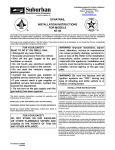
1
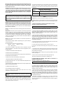
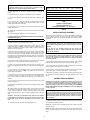
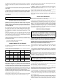
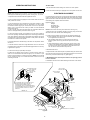
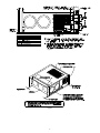
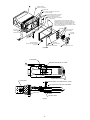
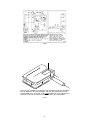
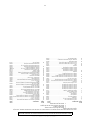
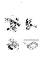
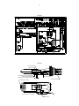
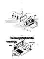
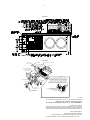
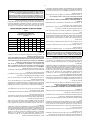
SUBURBAN MANUFACTURING COMPANY
676 Broadway Street
Dayton, Tennessee 37321
423-775-2131
www.rvcomfort.com
SUBURBAN GAS FURNACES
INSTALLATION INSTRUCTIONS FOR
MODELS
SF-20 • SF-25 • SF-30 • SF-35 • SF-42
The design of the furnace has been listed for installation in recreational vehicles only. In order for the furnace to operate in conformity
with generally accepted safety regulations, the installation instructions must be followed. Failure to comply with the installation
instructions will void the warranty on the furnace and any responsibility on the part of Suburban Manufacturing Company.
The furnace was inspected before it left the factory. If any parts are found to be damaged, do not install the furnace. Immediately
contact the transportation company and file a claim.
FOR YOUR SAFETY
WHAT TO DO IF YOU SMELL GAS:
• Extinguish any open flame.
• Evacuate all persons from the vehicle.
• Shut off the gas supply at the gas
container or source.
• Do not touch any electrical switch, or
use any phone or radio in the vehicle.
• Do not start the vehicle’s engine or
electric generator.
• Contact the nearest gas supplier or
qualified service technician for repairs.
• If you cannot reach a gas supplier or
qualified service technician, contact the
nearest fire department.
• Do not turn on the gas supply until the
gas leak(s) has been repaired.
This book contains instructions covering the operation and
maintenance of your furnace.
INSTALLER: LEAVE THIS MANUAL WITH THE APPLIANCE.
CONSUMER: RETAIN THIS MANUAL FOR FUTURE REFERENCE.
Should you require further information, contact your dealer or
nearest Suburban Service Center.
FOR YOUR SAFETY
DO NOT STORE OR USE GASOLINE
OR OTHER FLAMMABLE VAPORS AND
LIQUIDS IN THE VICINITY OF THIS OR
ANY OTHER APPLIANCE.
WARNING! Improper installation, adjustment, alteration, service or maintenance
can cause property damage, personal injury or loss of life. Refer to the installation
instructions and/or owners manual provided with this appliance. Installation and
service must be performed by a qualified
installer, service agency or the gas supplier.
WARNING! Be sure the furnace and all
ignition systems are “OFF” during any
type of refueling and while vehicle is in
motion or being towed.
INSTALLATION INSTRUCTIONS
WARNING! Installation of this appliance must be made in accordance
with the written instructions provided in this manual. No agent,
representative or employee of Suburban or other person has the
authority to change, modify or waive any provision of the instructions
contained in this manual.
These furnaces are designed and installed in such a manner as to be removable
only from the exterior of the recreational vehicle.
CAUTION: If possible, do not install the furnace to where the vent can be
covered or obstructed when any door on the trailer is opened. If this is not
possible, then the travel of the door must be restricted in order to provide
a 6” minimum clearance between the furnace vent and any door whenever
the door is opened.
NOTE: The exhaust temperature of this furnace could discolor or warp some
materials. You should verify that the material used on the coach door, panel, or
cover will not discolor or warp from the exhaust temperature whenever any door,
panel, or cover is in the open position.
CAUTION: Due to the differences in vinyl siding, this appliance should not be
installed on vinyl siding without first consulting with the manufacturer of the
siding or cutting the siding away from the area around the appliance vent.
CAUTION: In any installation in which the vent of this appliance can be
covered due to the construction of the RV or some special feature of the
Part Number 204638
10-23-08
RV such as slide out, pop-up etc. always insure that the appliance cannot
be operated by setting the thermostat to the positive “OFF” position and
shutting off all electrical and gas supply to the appliance. Never operate
furnace with vent covered.
It is important that adequate return air be provided to assure normal heating and
operation of the furnace. Failure to provide the minimum return air will cause
erratic furnace cycling. Refer to the chart shown below for minimum return air
requirements.
CAUTION: This furnace was shipped from the factory set up for the gas
connection to be made at the right rear of the unit as illustrated in Figure
1. If you wish to make gas connection through the top of cabinet, you must
remove furnace from cabinet and turn gas inlet fitting 90° CLOCKWISE.
DO NOT TURN FITTING COUNTER-CLOCKWISE, this will loosen fitting and
result in a gas leak.
Model
Return Air Requirements
Minimum Free (unobstructed) Area
SF-20/25/30/35
SF-42
WARNING! Hold manifold firmly when turning elbow to prevent any
force from being inserted on the valve and to prevent any leaks from
developing. Be sure to check all fittings for leaks including the inlet and
outlet on the valve before reinstalling furnace into cabinet. Correct all
leaks immediately. NOTE: The furnace must be in operation to properly
check for leaks.
55 Sq. In.
142 Sq. In.*
*May be reduced to 88 sq. in. min. if 5 ducts are used.
TABLE 1
NOTE: Return air must be from within the living area of the coach.
NOTE: RV’s that have a wall of separation to a cargo area (Toy Box) to transport
internal combustion engine vehicles must not have return air openings from this
area.
NOTE: These furnaces must be installed and vented as described in this manual
so that the negative pressure created by the air circulating (return air) fan cannot
affect the combustion air intake or venting of any other appliance. It is imperative
that the products of combustion be properly vented to the atmosphere and that
all combustion air supplied to burner be drawn from the outside atmosphere.
(See Installing Vent Assembly.)
A. INSTALLATION DIRECTLY AGAINST OUTER PANEL OF COACH
(See Figure 1) (Panel supplied by installer)
Maximum wall thickness for this type installation is 2”.
NOTE: Do not install the furnace with the vent facing toward the forward end of
the coach.
1. Locate the furnace near lengthwise center of the coach.
2. Choose a location for installation out of the way of wires, pipes, etc., which
might interfere with the installation. Adhere to the minimum clearances from the
cabinet to combustible construction as listed in Table 2. Refer to Figure 3 for
illustration of furnace clearances.
IMPORTANT: If this furnace is to be connected to a common duct system also
serving a cooling unit, a manual or automatic damper is required to prevent
any cold conditioned air from circulating back into the furnace. Cold air passing
over the furnace combustion chamber during the operation of the cooling unit
can result in the formation of condensation inside the furnace combustion
chamber. This condensation may promote corrosion and premature failure of
the combustion chamber.
NOTE: These furnaces shall be installed so the electrical components are
protected from water.
3. When an appliance is installed directly on carpeting, tile or other combustible
material, other than wood flooring, the appliance shall be installed on a metal or
wood panel extending the full width and depth of the appliance. If preferred, the
carpeting, tile or combustible materials, other than wood may be cut away the
full length and depth of the appliance plus the appliance minimum clearances to
combustibles. (See Table 2.)
These furnaces are design certified for propane/LP gas only. Do not attempt to
convert to natural gas.
4. Cut an opening through the inner wall. This will allow the rear of the furnace
to be installed against the outer panel of the coach.
Gas supply pressure for purposes of input adjustment:
Minimum - 11” W.C.*
Maximum - 13” W.C. *
(W.C.* - Water Column).
5. Locate center lines for exhaust and intake, as shown in Figure 1.
6. Cut two 2-1/4” diameter holes through the outer panel of the coach. (See
Figure 1.)
In the U.S.A., the installation of the furnace must be in accordance with local
codes and regulations. In the absence of local codes and regulations, refer to
the latest edition of:
7. Put furnace in place, making sure that rear of the furnace cabinet is as close
to outer panel of the coach as possible and still assure proper vent tube overlap.
(See Installing Vent Assembly.)
1. Standard for Recreational Vehicles NFPA 1192.
2. National Fuel Gas Code ANSI Z223.1.
8. Secure furnace to the floor using the two (2) holes provided in the furnace
cabinet. (See Figure 4).
3. Furnace must be electrically grounded in accordance with the latest edition of
the National Electrical Code NFPA 70.
9. Be sure furnace is secured within furnace cabinet. (See Figure 4).
10. Install vent assembly. (See instructions for installing vent.)
In Canada, the furnace must be installed in accordance with:
B. INSTALLATION NOT AGAINST OUTER PANEL OR SKIN AND “X”
DIMENSION GREATER THAN 1 ½”
(See Figure 2) (Exterior panel supplied by installer)
1. Standard CSA Z240.0.2-08 Recreational Vehicles.
2. CSA Standard Z240.6.2-08
Recreational Vehicles.
C22.2 NO.148-08 Electrical Requirements for
Maximum wall thickness for this type installation is 2”.
3. Standard Z240.4.2-08 Installation Requirements for Propane Appliances and
Equipment in Recreational Vehicles.
1. Locate the furnace near lengthwise center of the coach.
2. Choose a location for installation out of the way of wires, pipes, etc, which
might interfere with the installation. Adhere to the minimum clearances from
cabinet to combustible construction as listed in Table 2. Refer to Figure 3 for
illustration of furnace clearances.
4. CAN/CGA-B149 Installation Codes.
5. Any applicable local codes and regulations.
This unit is equipped with an electric igniter device that has an energy
consumption of .1 amp @ 12 volts D.C.
3. When an appliance is installed directly on carpeting, tile or other combustible
material, other than wood flooring, the appliance shall be installed on a metal or
wood panel extending the full width and depth of the appliance. If preferred, the
carpeting, tile or combustible materials, other than wood may be cut away the
full length and depth of the appliance plus the appliance minimum clearances to
combustible. (See Table 2.)
WARNING! Extension tubes cannot be used. If you try to extend the vent,
it will result in improper installation which could cause unsafe furnace
operation.
4. Determine “X” dimension as shown in Figure 2. The tubes supplied with
the furnace will accommodate an installation range for “X” from o-1 ½”. If “X”
dimension is greater than 1 ½”, then special vent tubes as charted in Figure 2
must be ordered.
There are three (3) methods described below for installing the furnace.
Regardless of the method you choose, we require an opening be provided in
the exterior of the trailer or motor home for free, unobstructed removal of the
furnace. This exterior, removable panel or wall section of the trailer or motor
home must be a minimum of 17-3/4 x 8.
2
WARNING ! Do not alter, cut, or otherwise modify the vent tubes as
supplied by Suburban. Doing so could result in inadequate intake of
combustion air or improper venting of furnace exhaust.
Model
Front
Left
Side
Right
Side
Top
Bottom
Back
Exhaust and
Intake Tube
5. After determining “X” dimension, complete the furnace installation as
follows:
SF-20
1”
0”
0”
0”
0”
0”
3/8”
SF-25
1”
0”
0”
0”
0”
0”
3/8”
6. Locate center lines for exhaust and intake tubes as shown in Figure 1.
SF-30
1”
0”
0”
0”
0”
0”
3/8”
SF-35
1”
0”
0”
0”
0”
0”
3/8”
SF-42
1”
2”
2”
1”
0”
0”
3/8”
7. Cut two 2-3/4” diameter holes through the outer panel or outer skin. (See
Figure 2.)
8. Put furnace in place, making sure that rear of furnace cabinet is as close
to inner wall section of the coach as possible and still assure proper vent tube
overlap. (See Installing Vent Assembly.)
-NOTE0” MEANS TO SPACER BUMPS
CLEARANCE FROM DUCTS TO
COMBUSTIBLE MATERIAL - 1/4” (See Figure 3)
9. Secure furnace to the floor using the two (2) holes provided in the furnace
cabinet. (See Figure 4.)
TABLE 2
10. Slide furnace into cabinet. Be sure furnace is secured within furnace cabinet
(See Figure 4.)
INSTALLING VENT ASSEMBLY
11. Install vent assembly. (See instructions for installing vent.)
The vent outlet must be installed so it is in the same atmospheric pressure zone
as the combustion air intake. The exhaust and intake tubes must be installed
from the outside, pass through the RV skin and slide onto the furnace exhaust
and intake.
C. INSTALLATION USING THE FURNACE ACCESS DOOR SUPPLIED BY SUBURBAN (See Figure 4)
Maximum wall thickness for this type installation is 2”.
WARNING! Discard the vent assembly that came with the furnace. The
vent cap assembly supplied with the vertical mounting kit must be
used. Suburban recommends all vents be installed using the rain shield
supplied.
1. Locate the furnace near lengthwise center of coach.
2. Choose a location for installation out of the way of wires, pipes, etc., which
might interfere with the installation. Adhere to the minimum clearances from the
cabinet to combustible construction as listed in Table 2. Refer to Figure 3 for
illustration of furnace clearances.
Do not alter the vent assembly supplied with this furnace. Any
modifications will result in improper installation which could cause
unsafe furnace operation.
3. When an appliance is installed directly on carpeting, tile or other combustible
material, other than wood flooring, the appliance shall be installed on a metal
or wood panel extending the full width and depth of the appliance. If preferred,
the carpeting, tile or combustible maters, other than wood may be cut away the
full length and depth of the appliance plus the appliance minimum clearances to
combustibles. (See Table 2.)
CAUTION! Combustion air must not be drawn from the living area. All air
for combustion must be drawn from the outside atmosphere. All exhaust
gases must be vented to the outside atmosphere - never inside the RV.
Therefore, it is essential to insure that the vent cap and tube assemblies
are properly installed.
4. After furnace location has been determined, cut an opening 18-7/32 x 8-9/32”
through the inner coach wall and the outer wall (skin) of the coach.
1. Apply caulking to RV skin behind vent cap as shown in Figure 1. Apply caulking
generously around perimeter of vent cap and across center as shown.
5. Caulk around opening as illustrated. Apply generously. The purpose of the
caulking is to seal the back side of the door frame and the coach skin water
tight.
2. Insert intake tube through RV skin and slide it onto the furnace intake (See
Figure 1.) Minimum tube overlap of 1/2” is required.
3. Insert vent cap exhaust tube through RV skin and slide it onto the furnace
exhaust (See Figure 1.) Minimum tube overlap of 1 1/4” is required.
6. Secure frame to outer wall (skin) through the holes in the frame. Screws
should be used. (See Figure 4.) NOTE: Do not place screws into the holes
required for mounting the door.
4. Attach vent cap assembly to outer skin of RV with the six (6) screws provided.
Do not install vent assembly upside down. The word “Suburban” must be right
side up.
7. Slide furnace in place. The back of the furnace should be installed against
or as close as possible to the flange on the door frame. (See illustration.) The
furnace must maintain 1/2” overlap on the intake and 1-1/4” overlap on the
exhaust.
CONNECTING GAS SUPPLY
8. Secure furnace to the floor using the two (2) holes provided in the furnace
cabinet. (See Figure 4.)
CAUTION: This furnace was shipped from the factory set up for the gas
connection to be made at the right rear of the unit as illustrated in Figure 1.
If you wish to make gas connection through the top of cabinet, you must
remove furnace from cabinet and turn gas inlet fittings 90° CLOCKWISE.
DO NOT TURN FITTING COUNTER-CLOCKWISE, this will loosen fitting and
result in a gas leak.
9. Slide furnace into cabinet. Be sure furnace is secured within furnace cabinet.
(See Figure 4.)
10. Position furnace access door over the frame. Secure the door to the coach
skin. Be sure the coach skin is of sufficient strength to keep furnace access door
in place and insure a tight seal. It may be necessary to build a wood or metal
frame around the opening in order to provide adequate strength for securing
door.
WARNING! Hold manifold firmly when turning elbow to prevent any
force from being inserted on the valve and to prevent any leaks from
developing. Be sure to check all fitting for leaks including the inlet and
outlet on the valve before reinstalling furnace into cabinet. Correct all
leaks immediately. NOTE: The furnace must be in operation to properly
check for leaks.
CAUTION: The screws provided with the door may not be of sufficient
length and size for all applications and it may be necessary for the installer
to substitute screws in order to adequately secure the furnace access
door.
Connect the gas supply to the furnace at the manifold, following the suggestions
outlined below. It will be necessary to hold the flare fitting on the furnace manifold
when connecting or loosening gas line.
11. Install vent assembly. (See instructions for installing vent.)
NOTE: The compound used on threaded joints must be resistant to liquefied
petroleum (LP) gas.
NOTE: The appliance must be disconnected from the gas supply piping system
during any pressure testing of that system at test pressure in excess of 1/2
PSIG.
3
E.Avoid making a lot of turns in the duct system. The straighter the duct system,
the better the performance of the furnace.
The appliance must be isolated from the gas supply piping during any pressure
testing of the gas supply piping system at test pressure equal to or less than
1/2 PSIG.
F. Maintain a minimum of 1/4” clearance where ducts pass through any
combustible construction, such as coach cabinetry. (See Figure 3.) NOTE: UL
listed duct materials can be 0” clearance.
1. A 3/8” male flare connection is provided for gas line hookup. Some standards
may require the use of a manual shut off valve in the gas line external to the
furnace cabinet.
G.Do not install air boosters in the duct system. Such devices will cause the
furnace to cycle on limit and to have erratic sail switch operation.
2. In order to maintain a check of gas supplied pressure to the furnace, Suburban advises
the installer to provide the 1/8” NPT plug tap for test gauge connection immediately
upstream of the gas supply connection to the furnace and that it be readily accessible.
NOTE: After installation of the furnace and duct system is completed, adjustments
must be made to obtain a temperature rise within the range specified on the
Rating Plate.
3. After the furnace has been connected to the gas supply, all joints must be
checked for leaks.
INSTALLING THERMOSTAT
WARNING! Never check for leaks with an open flame. Turn on the gas
and apply soapy water to all joints to see if bubbles are formed.
The thermostat used with this unit must have NO voltage output to return leg
when there is not a call for heat or in the “OFF” setting.
CONNECTING ELECTRICAL SUPPLY
Locate the room thermostat approximately 4-1/2 feet above the floor on an
inside bulkhead where it is not affected by heat from any source except room air.
Connect thermostat wiring to the blue wires on right side of furnace. (See wiring
diagram.) If your furnace is equipped with a thermostat that has an adjustable
anticipator, the anticipator should be set at .7 amps. If you desire longer heating
cycles, adjust the anticipator to a higher setting. If you desire shorter heating
cycles, adjust the anticipator to a lower setting. Adjustments to the anticipator
setting should be made in .5 amp increments.
CAUTION: This furnace is designed for negative ground 12 volt D.C.
system only. Do not attempt to alter the furnace for a positive ground
system or connect the furnace directly to 115 volts A.C. Damage to furnace
component parts will occur. Connect only to a protected circuit fused for
not more than 20 amps.
Be sure all wiring to the furnace is of heavy enough gauge to keep the voltage
drop through it to a minimum and to provide enough power for start-up surge.
No. 12 gauge wire is recommended. If any of the original wire that is supplied
with the appliance must be replaced, it must be replaced with type 105° C or its
equivalent.
PREVENTIVE MAINTENANCE
WARNING! If the user of this appliance fails to maintain it in the
condition in which it was shipped from the factory or if the appliance is
not used solely for its intended purpose or if appliance is not maintained
in accordance with the instructions in this manual, then the risk of a
fire and/or the production of carbon monoxide exists which can cause
personal injury, property damage or loss of life.
Power supply connections are to be on the right side of the furnace. The wires
are color coded, red for positive (+) and yellow for negative (-). This polarity
must be observed so the furnace motor will run the proper direction of rotation to
insure correct air delivery. (See wiring diagram.)
If the furnace power supply is to be from a converter, we recommend that the
converter system used to power the furnace be wired in parallel with the battery.
This will serve two purposes:
CAUTION: Label all wires before disconnecting for servicing. Proper
polarity must be observed so the furnace motor will run with the proper
direction of rotation to insure correct air delivery. (See wiring diagram).
1. Provide a constant voltage supply to the furnace.
2. Filter any A.C. spikes or volt surges.
CAUTION: Label all wires prior to disconnection when servicing controls.
Wiring error can cause improper and dangerous furnace operation.
Always verify proper operation of furnace after servicing.
CONNECTING DUCTS TO FURNACE
Your furnace should be inspected by a qualified service agency yearly before
turning the furnace on. Particular attention should be given to the following
items.
The following duct requirements must be followed in order to assure proper
operation of the furnace:
A. The minimum open duct areas listed below must be maintained throughout
entire duct system including through register:
MODEL
SIDE DUCTS
Min. Open
Duct Area
Min No.
Ducts Used
Duct
Size
TOP
DUCT
BOTTOM
DUCT
Min. Open
Duct Area
Min. Open
Duct Area
SF-20
25 SQ. IN.
2
4”
56 SQ. IN.
56 SQ. IN.
SF-25
36 SQ. IN.
3
4”
56 SQ. IN.
56 SQ. IN.
SF-30
36 SQ. IN.
3
4”
56 SQ. IN.
56 SQ. IN.
SF-35
48 SQ. IN.
4
4”
56 SQ. IN.
56 SQ. IN.
SF-42
48 SQ. IN.
4
4”
56 SQ. IN.
*72 SQ. IN.
1. Inspect furnace installation and vent termination to be sure furnace is
properly secured in place (see Installation Instructions), that vent terminates
to the atmosphere, and that vent tubes overlap properly (see Installing Vent
Assembly.)
2. Inspect chamber and venting to assure that these components are physically
sound without holes or excessive corrosion and that the installation and/or reinstallation is in accordance with Suburban’s installation instructions. (Reference
installation manual supplied with furnace.)
WARNING! It is imperative that the products of combustion be properly
vented to atmosphere and that all combustion air supplied to burner be
drawn from outside atmosphere.
3. Check the base on which furnace is mounted. Be sure it is physically sound,
void of any sagging, deterioration, etc.
*SF-42 Bottom Duct requires use of Bottom Duct Kit, Part No. 520753
NOTE: Ducts terminating in a dead air space (like holding tank
compartments or cargo areas (Toy Boxes) with no means for return air
recirculation should not be counted in the required duct area. Also ducts
2” in diameter or smaller should not be counted in the required duct area.
4. Inspect furnace, the venting, ducting and gas piping to furnace for obvious
signs of deterioration. Correct any defects at once.
5. Inspect combustion chamber for restrictions in exhaust or intake. It is
imperative that the flow of intake combustion air and the flow of exhaust gases
being expelled to the outside atmosphere not be obstructed. Any soot or loose
debris should be blown out using compressed air. (See Figure 7.)
B. No outlet register is to be placed within 18” of the return air opening. Any
register installed at 18” should never be toward the return air opening. If a register
is installed on a wall 90 degrees to the return air, it can be less than 18”.
C.Make the duct connections at the furnace cabinet tight. Loose connections
will result in overheating of the component parts on the furnace and a reduction
of the heated air flow through the duct system.
6. Inspect all gaskets. If any gaskets show signs of leakage or deterioration,
replace them. Safe operation of the furnace depends on all gaskets being tight.
7. Inspect return air inlet openings to the furnace. Remove any restrictions to
assure adequate air flow.
D.Avoid making any sharp turns in the duct system. Sharp turns will increase
the static pressure in the plenum area and could cause the furnace to cycle.
You, as the owner/user, should inspect the furnace monthly during the
heating season for presence of soot on vent. Operating the furnace under this
condition could lead to serious property damage, personal injury or loss of life.
4
If soot is observed on the vent, immediately shut the furnace down and contact
a qualified service agency.
INSTALLATION AND REMOVAL OF UNIT
INSTALLED FROM INSIDE
Listed below are several safety related items that you should follow during the
heating season to assure continued safe operation of the furnace.
TO REMOVE
1. Disconnect power supply at furnace.
1.Inspect furnace venting. Venting must be free of obstructions, void of soot, and
properly terminated to the atmosphere. (See Installing Vent Assembly.)
2. Remove vent cap assembly.
3. Disconnect gas connections.
WARNING! Do not install screens over the vent for any reason. Screens
will become restricted and cause unsafe furnace operation. Accessories
are being marketed for RV products which we do not recommend.
For your safety, only factory authorized parts are to be used on your
furnace
4. Remove cabinet front (2 screws).
5. Remove tie-down screw from center of unit and remove furnace from cabinet.
TO INSTALL
2. Periodically inspect the vent for obstructions or presence of soot. Soot is
formed whenever combustion is incomplete. This is your visual warning that the
furnace is operating in an unsafe manner. If soot is present, immediately shut
furnace down and contact your dealer or a qualified service person.
1. Slide unit into cabinet. NOTE: Care must be taken in routing wiring to back of
cabinet and outside of cabinet.
3. Keep furnace clean. More frequent cleaning may be required due to excessive
lint from carpeting, bedding material, etc. It is imperative that control compartments,
burners and circulating air passageways of the appliance be kept clean.
3. Reinstall cabinet front.
4. The motor is permanently lubricated and requires no oiling.
5. Check gas connections for leaks using a soap and water solution. Correct any
gas leaks immediately.
2. Reinstall tie-down screw.
4. Connect gas line.
5. Keep the furnace area clear of any combustible materials, gasoline or other
flammable vapor and liquids.
6. Reinstall vent cap assembly.
6. Before operating furnace, check the location of the furnace vent to make sure
it will not be blocked by the opening of any door on the trailer. If it can be blocked,
do not operate the furnace with the door open.
INSTALLATION AND REMOVAL OF UNIT
WHEN OPTIONAL BACK IS USED
TO REMOVE
7. Do not restrict the flow of combustion air or the warm air circulation to the
furnace. To do so could cause personal injury and/or death.
1. Break power to furnace.
8. Never operate the furnace if you smell gas. Do not assume that the smell of gas
is normal. Any time you detect the odor of gas, it is to be considered life threatening
and corrected immediately. Extinguish any open flames including cigarettes and
evacuate all persons from the vehicle. Shut off gas supply at LP gas bottle. (See
safety notice on front cover of this manual.)
2. Remove vent cap assembly.
3. Remove optional back.
4. Disconnect power supply at furnace.
9. Immediately shut furnace down and call a service agency if furnace cycles
erratically or delays on ignition.
5. Disconnect power supply plug from module board.
6. Disconnect electrode wire from module board.
WARNING! Should overheating occur, or the gas supply fail to shut off,
shut off the manual gas valve to the appliance before shutting off the
electrical supply.
7. Remove the two (2) screws securing module board and panel assembly to
firewall and pull out assembly. EXERCISE CARE NOT TO DAMAGE BOARD.
10. Never attempt to repair damaged parts. Always have them replaced by a
qualified service agency.
NOTE: This will allow more room for making the gas connections at the flare
fitting. It will be necessary to hold the flare fitting with a wrench when tightening or
loosening the gas line.
11. Never attempt to repair the furnace yourself. Seek the help of a qualified
service person.
8. Remove gas line.
12. Never restrict the ducting installed by your trailer manufacturer. To do so could
cause improper furnace operation.
9. Remove tie-down screw at blower base and remove furnace from cabinet.
TO REINSTALL
13. Do not install air boosters in the duct system. Such devices will cause the
furnace to cycle and to have erratic sail switch operation.
1. Slide unit into cabinet and secure with screw at base of blower.
14. Clothing or other flammable material should not be placed on or near the
appliance.
2. Connect gas line.
3. Check gas connections for leaks using a soap and water solution. Correct any
gas leaks immediately.
15. Always follow the operating instructions. Do not deviate from the step-by-step
procedures.
4. Reinstall module board and panel assembly.
16. Do not use this appliance if any part has been submerged under water.
Immediately call a qualified service technician to inspect the appliance and
to replace any part of the control system and any gas control that has been
submerged under water.
5. Reconnect electrode wire to board
6. Reconnect power supply to board.
17. When considering add-on rooms, porch or patio, attention must be given to
the venting of your furnace. For your safety, do not terminate furnace vent inside
add-on rooms, screen porch or onto patios. Doing so will result in products of
combustion being vented into the room or occupied areas.
7. Reconnect power to furnace. NOTE: If this connection was made inside the
cabinet, care must be exercised to prevent wires from coming in contact with the
room air blower wheel.
8. Reinstall optional back.
18. In any installation in which the vent of this appliance can be covered due to the
construction of the RV or some special feature of the RV such as slide out, pop-up,
etc. always insure that the appliance cannot be operated by setting the thermostat
to the positive “OFF” position and shutting off all electrical and gas supply to the
appliance. Never operate furnace with vent covered.
9. Reinstall vent cap.
10. Provide power to furnace.
5
OPERATING INSTRUCTIONS
TO SHUT DOWN
1. Set the thermostat to lowest setting, then move lever to “OFF” position.
WARNING! Do not operate furnace while vehicle is in motion or being
towed.
2. Turn manual shut off valve (if so equipped) to the “OFF” position. Do not force.
NOTE: During initial firing of this furnace, a burn-off of excess paint and oils
remaining from manufacturing process may cause “smoking” for 5 - 10 minutes.
ELECTRODE ADJUSTMENT
For consistent ignition of the burner, it is important that the electrode be positioned
properly over the top of the burner. The electrode was set at the factory for proper
ignition and should not need further adjustment; however, if you should experience
inconsistent ignition, reposition electrode as follows:
1. Stop! Read Users Information Manual supplied with furnace.
2. Turn the manual valve (if so equipped) or the valve at the outside LP tank to the
“OFF” position. Do not force.
Equipment needed:
flashlight
black felt-tip pen
needle-nose pliers
measuring tape
NOTE: Furnace must be removed. (See instructions for removing unit.)
3. Set thermostat above room temperature to begin blower operation. A slight
delay will occur before the blower comes on. Allow blower to run for 5 minutes
for combustion chamber purge cycle. If blower does not come on or stops before
ignition cycle, go to shut down and contact your dealer or a local recreational
vehicle service agency.
4. After 5 minutes, move thermostat lever below room temperature. Blower will
remain on. Wait approximately 2 minutes for blower to go off.
1. Remove burner from combustion chamber by removing six (6) screws which
attach the burner to the chamber and air baffles (plates).
5. Open manual shut-off valve (if so equipped) or the valve at the outside LP
tank. Correct operating characteristics depend on the valve being positioned fully
open. Never attempt to operate with a valve partially closed. NOTE: This furnace
is equipped with a valve shut-off switch with switch in “OFF” position. Gas will not
flow to burner nor will the furnace operate.
2. Locate the lance in relation to the burner ports for electrode positioning by:
a. Shine a flashlight into the burner venturi as illustrated. (Be sure flashlight lens is against the end of the burner.)
b. Light will reflect off the lance in the venturi of the burner and shine through a portion of the two (2) rolls of burner ports in the top of the burner.
c. Using a black felt-tip pen, mark a line along top of burner 3/16” in back of the lance and parallel with lance. Make an additional mark indicating the center line of the lance. (See illustration.) Both marks will be used later as reference marks; therefore, keep lines thin.
6. Set thermostat lever to desired setting. If set above room temperature, blower
will come on.
7. Allow 30 seconds for main burner to light after blower comes on. This furnace
is equipped with an ignition device which automatically lights the burner. Do not try
to light the burner by hand.
3. Reassemble the burner.
8. If burner does not light, repeat Steps 1 through 8.
4. Adjust electrode so the electrode probe is positioned along the marked center
line of the burner lance and the tip of the electrode terminates 3/16” from the back
of the lance. (At the line marked in Step 2-c.) (See Figure 5.)
9. If after three (3) attempts with no ignition, go to shut down and contact your
dealer or a local recreational vehicle service agency. Do not continue to cycle
furnace through thermostat in an attempt to get ignition. NOTE: If furnace should
lock out, the blower will go off in 5 minutes and remain off until unit is reset by
reactivating thermostat.
5. IMPORTANT: Be sure electrode probe maintains a 1/8” spark gap over the
burner as illustrated.
6. Reinstall the furnace into the cabinet following the instructions in the manual.
OUTSIDE SKIN (PANEL)
VENT CAP AND
EXHAUST TUBE
TUBE, INTAKE AIR
WITH GASKET
VENT CAP AND
EXHAUST
TUBE, AIR INTAKE
WITH GASKET
CAULK BEHIND VENT CAP AS SHOWN TO SEAL
BETWEEN EXHAUST AND INTAKE AND TO
PREVENT MOISTURE INSIDE FURNACE
COMPARTMENT. APPLY CAULKING GENEROUSLY
AROUND PERIMETER OF VENT CAP AND ACROSS
CENTER AS SHOWN. CENTER PUTTY STRIP IS
ESSENTIAL.
SEE DETAIL "A"
(2) 2 1/4"
DIA. HOLES
DETAIL "A"
REMOVABLE PANEL OF
COACH WALL MUST
SEAL WATER TIGHT
OUTSIDE SKIN (PANEL)
ELECTRICAL
CONNECTION
FRONT
GAS CONNECTION
INSIDE WALL
FURNACE CABINET
Figure 1
6
2" MAXIMUM WALL THICKNESS
Figure 2
Figure 3
7
TIE-DOWN SCREW
(FURNACE TO CABINET)
OUTSIDE SKIN
CAULK ALONG THE EDGE OF THE CUTOUT
(ALL THE WAY AROUND)
ANCHOR FURNACE CABINET TO COACH
FLOOR (2) PLACES AS ILLUSTRATED
BACK OF CABINET MUST BUTT
AGAINST THIS EDGE OF THE FRAME
DOOR FRAME
CAULK BEHIND VENT CAP AS SHOWN TO SEAL
BETWEEN EXHAUST AND INTAKE AND TO PREVENT
MOISTURE INSIDE FURNACE COMPARTMENT. APPLY
CAULKING GENEROUSLY AROUND PERIMETER OF
VENT CAP AND ACROSS CENTER AS SHOWN. CENTER
PUTTY STRIP IS ESSENTIAL.
ELECTRICAL
CONNECTION
AIR INTAKE TUBE
WITH GASKET
GAS
CONNECTION
6 SCREWS
(SUPPLIED)
4 SCREWS
DOOR MOUNTING
SECURE FRAME TO
OUTER PANEL WITH SCREWS
(16 PLACES)
FURNACE ACCESS DOOR
VENT CAP & EXHAUST TUBE
Figure 4
ELECTRODE
MARKED CENTERLINE OF LANCE
TOP OF BURNER
FRONT END OF BURNER
FLASHLIGHT
MARK BURNER .187 FROM BACK OF LANCE
.125 SPARK GAP OVER TOP OF BURNER
SIDE OF BURNER
LIGHT BEAM
LANCE
VENTURI TUBE
Figure 5
8
Figure 6
TO CLEAN THE CHAMBER, THE FURNACE MUST BE REMOVED FROM THE CABINET
AND THE MANIFOLD. BLOWER ASSEMBLY AND CONTROLS REMOVED LEAVING
THE CHAMBER ONLY, AS SHOWN. USING COMPRESSED AIR, BLOW THROUGH THE
CHAMBER, AS SHOWN BY ARROWS, TO REMOVE SOOT OR LOOSE DEBRIS.
Figure 7
9
9
28
26
11
12
27
24
15
23
16
15
15
22
15
15
Figure 8
Figure 9
36
48
36
49
50
42
43
37
51
52
44
41
45
38
39
40
36
35
54
34
56
58
57
31
59
62
32
Figure 10
10
13
14
15
19
REPLACEMENT PARTS LIST
Only factory authorized parts are to be used. Do not attempt to repair defective parts.
When ordering repair parts from your dealer, a Suburban Service Center, or distributor, always give the following information:
1. Part Number (Not Item No.)
2. Part Description
3. Model and Serial Number of furnace
4. Number of Parts Required
Item
No.
Description
1
1A
2
5
5B
5C
6
7
9
11
12
13
14
15
16
19
22
23
24
26
27
28
Part
Number
Clamp, Wire.................................................................................................062180
Item
No.
Description
Cabinet Front (SF-35/42)............................................................................101242
Cabinet Front (SF-20/25/30).......................................................................102316
Thermostat.................................................................................................. 161154
Cabinet Assembly (SF-20/25/30)................................................................101889
Cabinet Assembly (SF-35)..........................................................................101893
Cabinet Assembly (SF-42)..........................................................................101894
Bracket, Mounting (Rear)............................................................................063250
Bracket, Mounting (Front)...........................................................................063343
Cover, Duct..................................................................................................050733
Collar, Duct..................................................................................................050715
Manifold Assembly Complete ....................................................................171743
Orifice, Main Burner (SF-20).......................................................................180305
Orifice, Main Burner (SF-25).......................................................................180306
Orifice, Main Burner (SF-30).......................................................................180307
Orifice, Main Burner (SF-35).......................................................................180308
Orifice, Main Burner (SF-42).......................................................................180309
Gasket, Burner Access Door.......................................................................071263
Tinnerman...................................................................................................121704
Plate, Secondary Air (Top-Back Half) (SF20/25/30/42)..............................063198
Plate,Secondary Air (Top-Back Half) (SF-35).............................................063199
Screw 8-18 x 1/2 Stainless.........................................................................121651
Plate, Secondary Air (Top-Front Half) (SF-20/25/30/42)............................062933
Plate, Secondary Air (Top-Front Half) (SF-35)............................................062936
Plate, Secondary Air (Bottom) (SF-20/25/30/42)........................................062935
Plate, Secondary Air (Bottom) SF-35)........................................................062938
Electrode.....................................................................................................232286
Burner Assembly Complete (SF-20)...........................................................010767
Burner Assembly Complete (SF-25)...........................................................010762
Burner Assembly Complete (SF-30/35)......................................................010865
Burner Assembly Complete (SF-42)...........................................................010799
Grommet.....................................................................................................070963
Valve............................................................................................................ 161122
Pipe Assembly, Gas Inlet............................................................................171574
31
32
33
34
35
36
37
38
39
40
41
42
43
44
45
48
49
50
51
52
54
56
57
58
59
62
11
Part
Number
Vent Cap and Exhaust Tube Assembly......................................................260231
Tube Assembly Intake (Vent)......................................................................051248
Rain Shield..................................................................................................280582
Combustion Air Housing Assembly (Front Half).........................................390852
Screw #8-18 x 2 1/4 (4 Required)...............................................................121929
Screw #6-19 x 1/2 (7 Required)..................................................................121928
Combustion Air Housing (Rear Half) (SF-20).............................................390849
Combustion Air Housing (Rear Half) (SF-25/30/35/42)..............................390848
Wheel, Combustion Air (SF-20)..................................................................350189
Wheel, Combustion Air (SF-25/30/35)........................................................350184
Wheel, Combustion Air (SF-42)..................................................................350183
Gasket, Firewall (Combustion Air)..............................................................071084
Motor Assembly with Gasket (SF-20/25/30)...............................................232682
Motor Assembly with Gasket (SF-35).........................................................232684
Motor Assembly with Gasket (SF-42).........................................................232683
Screw # 4-24 X 5/8 (2 Required) ...............................................................121971
Blower Assembly (Room Air) Front Half (SF-20, 25, 30. 35)......................390872
Blower Assembly (Room Air) Front Half (SF-42)........................................390873
Screw #8-18 X 1/2 (4 Required).................................................................121857
Blower Housing (Room Air) Rear Half........................................................390851
Switch, Sail..................................................................................................232261
Switch ON/OFF...........................................................................................232351
Bracket, ON/OFF Switch.............................................................................063446
Module Board..............................................................................................520820
Insulator Cap, Module Board Coil...............................................................070973
Blower Wheel Assy (Room Air)...................................................................350129
Bushing, Universal......................................................................................070362
Bushing, Strain Relief..................................................................................071206
Gasket, Firewall (Chamber Side)................................................................071262
Chamber Assy. Final (SF-20, 25, 30, 35)...............................................021206BK
Chamber Assy. Final (SF-42)......................................................................021207
Switch, Limit (SF-20)...................................................................................232503
Switch, Limit (SF-25, 30, 35).......................................................................232504
Switch, Limit (SF-42)...................................................................................232505
Firewall........................................................................................................ 110778
TWO YEAR LIMITED WARRANTY
SUBURBAN RECREATIONAL VEHICLE FURNACE
TWO YEAR LIMITED WARRANTY
This Suburban product is warranted to the original purchaser to be free from defects in material and workmanship under normal use and maintenance for a period of two
years from date of purchase whether or not actual use begins on that date. It is the responsibility of the consumer/owner to establish the warranty period. Suburban does
not use warranty registration cards for its standard warranty. You are required to furnish proof of purchase date through a Bill of Sale or other payment records.
Suburban will replace any parts that are found defective within the first two years and will pay a warranty service allowance directly to the recommended Suburban
Service Center at rates mutually agreed upon between Suburban and its recommended service centers. Replacement parts will be shipped FOB the shipping point
within the Continental United States, Alaska and Canada to the recommended service center performing such repairs. All freight, shipping and delivery cost shall be
the responsibility of the owner. The exchanged part or unit will be warranted for only the unexpired portion of the original warranty. Before having warranty repairs
made, confirm that the service agency is a recommended service center for Suburban. DO NOT PAY THE SERVICE AGENCY FOR WARRANTY REPAIRS; SUCH
PAYMENTS WILL NOT BE REIMBURSED.
For warranty service, the owner/user should contact the nearest recommended Suburban Service Center, advising them of the model and serial numbers (located on
the furnace) and the nature of the defect. Transportation of the RV to and from the Service Center and/or travel expenses of the Service Center to your location is the
responsibility of the owner/user. A current listing of recommended service centers may be obtained from Suburban’s website, www.rvcomfort.com. If you cannot locate
a recommended service center locally, the service agency chosen to perform warranty repairs must contact our Service Department at 423-775-2131 for authorization
before making repairs. Unauthorized repairs made will not be paid by Suburban.
THREE YEAR LIMITED WARRANTY ON HEAT EXCHANGER
The furnace heat exchanger is further warranted to be free from defects in material and workmanship during the third through fifth year after the date of original purchase.
A replacement heat exchanger will be provided under the same conditions as stated in the two year warranty EXCEPT no labor reimbursement will be provided.
LIMITATION OF WARRANTIES
ALL IMPLIED WARRANTIES (INCLUDING IMPLIED WARRANTIES OF MERCHANTABILITY) ARE HEREBY LIMITED IN DURATION TO THE PERIOD FOR
WHICH EACH LIMITED WARRANTY IS GIVEN. SOME STATES DO NOT ALLOW LIMITATIONS ON HOW LONG AN IMPLIED WARRANTY LASTS SO THE
ABOVE LIMITATIONS MAY NOT APPLY TO YOU. THE EXPRESSED WARRANTIES MADE IN THIS WARRANTY ARE EXCLUSIVE AND MAY NOT BE ALTERED,
ENLARGED, OR CHANGED BY ANY DISTRIBUTOR, DEALER OR OTHER PERSON WHOMSOEVER.
SUBURBAN WILL NOT BE RESPONSIBLE FOR:
1. Normal maintenance as outlined in the installation, operating and service instructions owner’s manual including cleaning of component parts; such as, orifices and
burners.
2. Initial checkouts and subsequent checkouts which indicate the furnace is operating properly, or diagnosis without repair.
3. Damage or repairs required as a consequence of faulty or incorrect installation or application not in conformance with Suburban instructions.
4. Failure to start and/or operate due to loose or disconnected wires; water or dirt in controls, fuel lines and gas tanks; restriction or alteration of return air circulation;
low voltage.
5. Routine adjustments that may be required to the thermostat, electrode and burner.
6. Costs incurred in gaining access to the furnace.
7. Parts or accessories not supplied by Suburban.
8. Freight charges incurred from parts replacements.
9. Damage or repairs needed as a consequence of any misapplication, abuse, unreasonable use, unauthorized alteration, improper service, improper operation or
failure to provide reasonable and necessary maintenance.
10. Suburban products whose serial number has been altered, defaced or removed.
11. Suburban products installed or warranty claims originating outside the Continental U.S.A., Alaska, Hawaii and Canada.
12. Damage as a result of floods, winds, lightning, accidents, corrosive atmosphere or other conditions beyond the control of Suburban.
13. ANY SPECIAL, INDIRECT OR CONSEQUENTIAL PROPERTY, ECONOMIC OR COMMERCIAL DAMAGE OF ANY NATURE WHATSOEVER. Some states do
not allow the exclusion of incidental or consequential damages, so the above limitation may not apply to you.
NO REPRESENTATIVE, DEALER, RECOMMENDED SERVICE CENTER OR OTHER PERSON IS AUTHORIZED TO ASSUME FOR SUBURBAN MANUFACTURING
COMPANY ANY ADDITIONAL, DIFFERENT OR OTHER LIABILITY IN CONNECTION WITH THE SALE OF THIS SUBURBAN PRODUCT.
This warranty gives you specific legal rights, and you may also have other rights which vary from state to state.
IF YOU HAVE A PRODUCT PROBLEM
FIRST:
If your RV has its original furnace and is still under the RV manufacturer’s warranty, follow the steps suggested by your dealer or manufacturer of the RV.
SECOND:
Contact a conveniently located recommended Suburban Service Center. Describe to them the nature of your problem, make an appointment, if necessary, and provide
for delivery of your RV to the selected service center.
THIRD:
For the location of the nearest service center, refer to the listing provided or contact:
Suburban Manufacturing Company
Customer Service Department
676 Broadway Street
Dayton, Tennessee 37321
(423) 775-2131, Ext. 7101
www.rvcomfort.com
For future reference, you should record the following information
MODEL NUMBER _________________________________
SERIAL NUMBER _________________________________
STOCK NUMBER _________________________________
DATE OF PURCHASE _____________________________
GARANTIE LIMITÉE DE DEUX ANNÉES
SUBURBAN - CHAUFFE-EAU POUR VÉHICULE RÉCRÉATIF
GARANTIE LIMITÉE DE DEUX ANNÉE
Ce produit Suburban est garanti au bénéfice du premier acquéreur comme étant exempt de vice de matériau ou de fabrication, lorsqu’il est soumis aux conditions
normales d’utilisation et d’entretien, pendant une période de deux ans à compter de la date d’achat, que l’appareil soit ou non mis en service à cette date. C’est au
consommateur/propriétaire qu’incombe la responsabilité de faire la preuve de la période de garantie. Suburban n’utilise pas de carte d’enregistrement de la garantie
pour sa garantie standard. Le propriétaire doit soumettre une preuve de la date d’achat, comme une facture ou un autre document attestant du paiement.
Au cours des deux premières années, Suburban remplacera toute pièce s’avérant être défectueuse, et versera une allocation de main-d’oeuvre sous garantie
directement au centre de service Suburban recommendé, selon le tarif défini par accord mutuel entre Suburban et ses centres de service recommendé s. Les pièces
de rechange seront expédiées F.-à-B. point d’expédition au centre de service Suburban recommendé effectuant les réparations dans les états continentaux des
États-Unis, en Alaska et au Canada. Le propriétaire devra assumer tous les frais de fret, expédition et livraison. Une pièce ou un composant remplacé ne bénéficie de
la garantie que pendant la fraction non écoulée de la période de garantie d’origine. Avant de faire effectuer des réparations sous garantie, vérifier que l’établissement
de réparation est un centre de service recommendé par Suburban. NE PAS PAYER DES FRAIS DE MAIN-D’OEUVRE AUX ÉTABLISSEMENTS DE RÉPARATION
POUR DES RÉPARATIONS SOUS GARANTIE; CES FRAIS NE VOUS SERONT PAS REMBOURSÉS.
Suburban se réserve le droit d’inspecter le chauffe-eau ou le composant incriminé pour en vérifier les défectuosités; c’est au propriétaire qu’incombe l’obligation
de retourner le chauffe-eau et/ou les composants à Suburban ou à son représentant. Un chauffe-eau retourné doit comprendre tous ses composants et la plaque
signalétique. Des composants retournés indépendants doivent être étiquetés et identifiés avec le numéro de modèle et le numéro de série du chauffe-eau, et la date
d’installation.
Pour obtenir les services nécessaires sous garantie, le propriétaire devrait contacter le plus proche centre de service Suburban recommendé, en mentionnant le
numéro de modèle et le numéro de série (indiqués sur l’appareil), et la nature de l’anomalie. Le propriétaire/utilisateur doit assumer les frais de transport du véhicule
récréatif entre son domicile et le centre de service, ou les frais de déplacement du personnel du centre de service. On peut obtenir une liste récente des centres de
service recommendés a Suburban’s l’addresse: www.rvcomfort.com. Advenant qu’il n’y ait pas de centre de service agréé local, le personnel du centre de service
choisi pour l’exécution de travaux sous garantie doit contacter notre département de service au numéro 423-775-2131 avant d’effectuer les réparations pour obtenir
une autorisation. Suburban ne paiera pas les réparations effectuées sans autorisation.
GARANTIE LIMITÉE SUR LE RÉSERVOIR - TROIS ANS
Le réservoir interne est également garanti comme étant exempt de vice de matériau ou de fabrication pendant une période de trois ans à compter de la date de
l’acquisition initiale. Un chauffe-eau de remplacement sera fourni dans les mêmes conditions déjà indiquées pour la garantie de deux années, À L’EXCEPTION que
Suburban ne remboursera aucun frais de main-d’oeuvre.
LIMITATION DES GARANTIES
LA PÉRIODE DE VALIDITÉ DES GARANTIES IMPLICITES (CECI INCLUANT LES GARANTIES IMPLICITES DE QUALITÉ MARCHANDE) EST EXPRESSÉMENT
LIMITÉE À LA DURÉE DE CHAQUE PÉRIODE DE GARANTIE LIMITÉE ACCORDÉE. CERTAINES PROVINCES N’ADMETTENT PAS LA LIMITATION DE LA
DURÉE DE VALIDITÉ DES GARANTIES IMPLICITES; PAR CONSÉQUENT, LES LIMITATIONS CI-DESSUS PEUVENT NE PAS VOUS ÊTRE APPLICABLES.
LES GARANTIES EXPRESSES CONFÉRÉES PAR LE TEXTE QUI PRÉCÈDE SONT LES SEULES GARANTIES ACCORDÉES, ET ELLES NE PEUVENT ÊTRE
MODIFIÉES, ÉTENDUES OU PROLONGÉES PAR UN DISTRIBUTEUR, CONCESSIONNAIRE OU AUTRE PERSONNE.
SUBURBAN N’ACCEPTERA AUCUNE RESPONSABILITÉ AU TITRE DE:
1. Entretien normal, tel qu’il est défini dans les instructions d’installation, utilisation et entretien du manuel de l’utilisateur, ceci incluant le nettoyage des composants
et le nettoyage ou remplacement du gicleur du brûleur. Les dégâts provoqués par l’eau, découlant directement ou indirectement d’un défaut du chauffe-eau ou d’un
composant, ou de son utilisation.
2. Inspection initiale et inspections ultérieures indiquant que l’appareil fonctionne correctement, ou diagnostic sans réparation.
3. Dommages ou réparations imputables à une installation déficiente ou à une application non conforme aux instructions de Suburban.
4. Impossibilité de mise en marche et/ou de fonctionnement imputable à déficiences des fils ou raccordements, présence d’eau ou souillures dans les organes de
commande, canalisations de combustible et réservoirs de gaz; pression de gaz incorrecte; tension électrique insuffisante.
5. Nettoyage ou réglage pour composants, électrode, tube de brûleur, brûleur de veille et thermocouple.
6. Frais rendus nécessaires pour l’accès à l’appareil.
7. Pices ou accessoires non fournis par Suburban.
8. Frais de transport afférents au remplacement de pièces.
9. Dommages ou réparations imputables à toute utilisation impropre, irraisonnée ou abusive, modification non autorisée, travaux d’entretien incorrects, utilisation
incorrecte ou carence d’entretien.
10. Produits Suburban dont le numéro de série a été modifié, éliminé ou rendu illisible.
11. Produits Suburban installés ou utilisés hors des zones géographiques suivantes: états continentaux des É.-U., Alaska, Hawaii et Canada.
12. Dommages imputables à inondation, vent, foudre, accident, atmosphère corrosive et autres situations que Suburban ne peut contrôler.
13. DOMMAGES SECONDAIRES OU INDIRECTS MATÉRIELS, ÉCONOMIQUES OU COMMERCIAUX, QUELLE QU’EN SOIT LA NATURE. Certaines provinces
n’admettent pas l’exclusion des dommages secondaires ou indirects; par conséquent, la limitation ci-dessus peut ne pas vous être applicable.
AUCUN REPRÉSENTANT, CONCESSIONNAIRE, DES CENTRES DE SERVICE RECOMMENDÉ OU AUTRE PERSONNE N’EST AUTORISÉ À ASSUMER
AU NOM DE SUBURBAN MANUFACTURING COMPANY DES OBLIGATIONS ADDITIONNELLES OU DIFFÉRENTES EN RAPPORT AVEC LA VENTE DE CE
PRODUIT SUBURBAN.
Cette garantie vous confère des droits juridiques spécifiques; vous pouvez également jouir d’autres droits, variables d’une province à une autre.
SI UN PROBLÈME SE MANIFESTE
TOUT D’ABORD:
Si le véhicule récréatif est encore équipé de son chauffe-eau d’origine et est encore couvert par la garantie de son constructeur, procéder conformément aux
instructions de concessionraire ou constructeur de votre véhicule récréatif.
DEUXIÈMEMENT :
Contacter un centre de service Suburban recommendé peu éloigné. Décrire la nature du problème au technicien, prendre rendez-vous si c’est nécessaire, et
organiser la livraison de votre véhicule récréatif au centre de service choisi.
TROISIÈMEMENT:
Pour localiser le centre de service de réparation le plus proche, référez vous à la liste fournie ou contactez:
Suburban Manufacturing Company
Customer Service Department
676 Broadway Street
Dayton, Tennessee 37321
(423) 775-2131, Ext.7101
www.rvcomfort.com
Pour rèfèrence, inscrire ci-dessous descriptive de l’appareil:
NUÉÈRO DE MODÈLE__________________________________
NUMÉRO DE SÉRIE ___________________________________
NUMÉRO DE STOCK __________________________________
DATE D’ACHAT_______________________________________
LISTE DES PIÈCES DE RECHANGE
Utiliser uniquement des pièces autorisées par l’usine. Ne pas tenter de réparer les composants défectueux.
Lors de la commande de pièces de rechange auprès d’un concessionnaire ou d’un centre de service ou distributeur Suburban, communiquer
toujours l’information suivante.
1. Numéro de pièce (pas le numéro d’article)
2. Description de la pièce
3. Numéro de modèle et numéro de série de l’appareil
4. Nombre de pièces demandées
N° de
N° de
N° de
N° de
repère
Description
pièce
repère Description
pièce
1
1A
2
5
6
7
9
11
12
13
14
15
16
19
22
23
24
26
27
28
31
32
Avant de la caisse (SF-35, 42)................................................................ 101242
Avant de la caisse (SF-20, 25, 30).......................................................... 102316
Thermostat...............................................................................................161154
Caisse (SF-20,25,30).............................................................................. 101889
Caisse (SF-35)........................................................................................ 101893
Caisse (SF42)......................................................................................... 101894
Couvercle, conduit.................................................................................. 050733
Bride de fixation, conduit........................................................................ 050715
Système de distribution, complete.......................................................... 171743
Gicleur à gaz, brûleur principal SF-20.................................................... 180305
Gicleur à gaz, brûleur principal SF-25.................................................... 180306
Gicleur à gaz, brûleur principal SF-30.................................................... 180307
Gicleur à gaz, brûleur principal SF-35.................................................... 180308
Gicleur à gaz, brûleur principal SF-42 ................................................... 180309
Joint, couvercle d’accès au brûleur........................................................ 071263
Tinnerman............................................................................................... 121704
Plaque, air secondaire (sommet, moitié arrière) (SF-20,25,30,42)......... 063198
Plaque, air secondaire (sommet, moitié arrière) (SF-35)........................ 063199
Vis N° 8-18 x 1/2, inox............................................................................ 121651
Plaque, air secondaire (sommet, moitié avant) (SF-20,25,30,42).......... 062933
Plaque, air secondaire (sommet, moitié avant) (SF-35)......................... 062936
Plaque, air secondaire (bas) (SF-20,25,30,42)....................................... 062935
Plaque, air secondaire (bas) (SF-35)...................................................... 062938
Électrode................................................................................................. 232286
Brûleur, ensemble complet (SF-20)........................................................ 010767
Brûleur, ensemble complet (SF-25)........................................................ 010762
Brûleur, ensemble complet (SF-30,35)................................................... 010865
Brûleur, ensemble complet (SF-42)........................................................ 010799
Passe-fil.................................................................................................. 070963
Valve........................................................................................................161122
Tuyau, arrivée du gaz(modèles à gaz arrière)........................................ 171574
Tuyau, arrivée du gaz (modèles à gaz avant)......................................... 171576
Bride de serrage, fil................................................................................. 062180
Ensemble - bouches d’admission d’air/décharge................................... 260553
Tube ďadmission ďair............................................................................. 051248
34
35
36
37
38
39
40
41
42
43
44
45
48
49
50
51
52
54
56
57
58
59
62 Montage de chambre pour combustion ďair (partie avant)................... 390852
Vis N° 8-18 x 2 1/4 (4)..........................................................................121929
Vis N° 6-19 x 1/2 (7).............................................................................121928
Montage de chambre pour combustion d’air (partie arriére) (SF-20)... 390849
Montage de chambre pour combustion d’air (partie arriére)
(SF-25,30,35,42)..................................................................................390848
Turbine, air de combustion (SF-20)......................................................350189
Turbine, air de combustion (SF-25,30,35)............................................ 350184
Turbine, air de combustion (SF-42)......................................................350183
Joint, cloison pare-feu (côté ventilateur)............................................... 071084
Moteur Avec Joint D’e Chantèitè (SF-20,25,30)................................... 232682
Moteur Avec Joint D’e Chantèitè (SF-35)............................................. 232684
Moteur Avec Joint D’e Chantèetè (SF-42)............................................ 232683
Vis N° 4-24 x 5/8 (2).............................................................................121971
Système ďassemblage ventilateur (air ambiant) partie avant
(SF-25, 25, 30, 35)...............................................................................390872
Systéme ďassemblage ventilateur (air ambiant) partie avant
(SF-42).................................................................................................390873
Vis N° 8-18 x 1/2 (4)............................