1
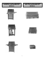
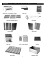
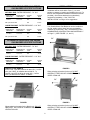
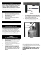
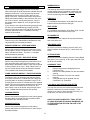
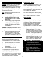
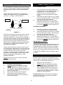
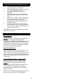
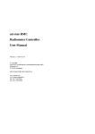
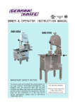
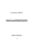
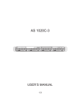
INSTALLATION
AND OPERATION
INSTRUCTIONS
TABLE OF CONTENTS
GENERAL INFORMATION
MODELS
SHIPPING AND PACKING LIST
SAFETY INFORMATION
SPECIFICATIONS - Carts & Pedestals
INSTALLATION - Carts & Pedestals
SET-UP & ASSEMBLY - Carts & Pedestals
INSTALLATION - Built-ins
LIQUID PROPANE INFORMATION
NATURAL GAS INFORMATION
OPERATION
MAINTENANCE
PARTS LISTING
TROUBLE SHOOTING
WARRANTY
STRAUBELSTONE STEELMAN &
EXECUTIVE GAS BARBECUE CARTS,
PEDESTALS & BUILT-INS
CONGRATULATIONS, on the purchase of your new
STRAUBELSTONE GAS BARBECUE. These units are
designed and intended for outdoor use only.
GENERAL INFORMATION
These instructions are intended as a general guide and
do not supersede national or local codes in any way.
Authorities having jurisdiction should be consulted
before installation.
1
2
5
5
6
6
7
10
12
14
16
18
20
27
28
!!! WARNING !!!
Gas supply system must be installed in accordance with
the U.S. National Fuel Gas Code.
Installation and provision for combustion and ventilation
air must conform to the National Fuel Gas Code, ANSI
Z223.1, or CAN/CGA-B149.1, Natural Gas Installation
Code, or CAN/CGA-B149.2, Propane Installation Code.
This barbecue has been tested to, and complies with,
ANSI Z21.58 and CAN/CGA 1.6 ( 1995 ), STANDARDS
FOR OUTDOOR COOKING GAS APPLIANCES.
This appliance and its individual shut off valve must be
disconnected from the gas supply piping system during
any system pressure test in excess of ½ PSI ( 3.5 KPA ).
Use a system manual shut off valve to shut off the gas
supply to this gas appliance before continuing with
installation procedures.
!!! IMPORTANT !!!
Read these instructions carefully before installing or
operating this gas barbecue. These instructions should
be left with the homeowner for future reference.
GAS-FIRED OUTDOOR COOKING APPLIANCE IN
ACCORDANCE WITH THE AMERICAN NATIONAL
STANDARDS INSTITUTE (ANSI) STANDARD FOR
OUTDOOR COOKING GAS APPLIANCES Z21.581995 83EK
!!! WARNING !!!
If the information in this manual is not followed exactly, a
fire or explosion may result causing property damage,
personal injury or loss of life.
WHAT TO DO IF YOU SMELL GAS:
< Shut off gas supply to the appliance.
Do not store combustible materials or use
gasoline or other flammable vapors and
liquids in the vicinity of this or any other
appliance.
< Extinguish any open flames.
< Open barbecue lid.
A liquid propane tank, not connected for
use with this gas barbecue, shall not be
stored in the vicinity of this or any other
appliance.
< If odor continues, Immediately call your
gas supplier. Follow the gas supplier’s
instructions.
< If you can not reach your gas supplier,
call the fire department.
Installation and service must be performed
by a: Qualified technician, service agency,
or the gas supplier.
1
STRAUBELSTONE STEELMAN
GAS BARBECUE MODELS
STRAUBELSTONE EXECUTIVE
GAS BARBECUE MODELS
2
STRAUBELSTONE STEELMAN
PEDESTAL GAS BARBECUE
MODELS
STRAUBELSTONE STEELMAN
BUILT-IN GAS BARBECUE
MODELS
3
STRAUBELSTONE GAS BARBECUE ACCESSORIES
UNDER SHELF & CONDIMENT HOLDER
SIDE SHELF
COOKING & SEARING GRATES
ROTISSERIE
DOOR PANELS
SIDE GRILL
COVER
SIDE PANELS
DEEP FRYER & BASKET
MESH SHELF
GRIDDLE
CONDIMENT TRAY
4
PROPER CLEARANCES FROM COMBUSTIBLE
CONSTRUCTION AND MATERIALS MUST BE
MAINTAINED FROM ALL SIDES, TOP, AND BOTTOM
OF THIS APPLIANCE ( 24" IN ANY DIRECTION ).
SHIPPING AND PACKING LIST
Your STRAUBELSTONE GAS BARBECUE comes assembled,
ready for the gas connection, with the exception of hood and/or
shelf assembly, wheel and axle assembly, condiment holder,
and handle on some models.
THIS APPLIANCE SHOULD NEVER BE PLACED
NEAR ANY COMBUSTIBLE SURFACE.
SHIPPING CARTON CONTAINS:
12112-
THIS APPLIANCE SHOULD NEVER BE PLACED
UNDER ANY COMBUSTIBLE CONSTRUCTION OR
MATERIALS.
StraubelStone Gas Barbecue
Gas Barbecue Cooking Grates
Gas Barbecue Warming Rack
Gas Barbecue Manual Pack with Warranty Card
Chassis Installation Brackets ( Built-ins only )
THIS APPLIANCE SHOULD NEVER BE PLACED
CLOSER THAN TWENTY-FOUR ( 24 ) INCHES FROM
ANY SIDE OR BACK, TO ANY COMBUSTIBLE
CONSTRUCTION OR MATERIAL. ( FIGURE 1,2 & 3 )
OPTIONAL ACCESSORIES:
( included on some models )
11111111122111111-
LP tank, regulator, and hose assembly
Liquid Propane models only
Extra Top Cooking Grate
Cutting Board
Gas Barbecue Cover
Rotisserie Kit
Searing Grate
Under Shelf
Condiment Holder
Side Shelf
Door Panels
Side Panels
Side Grill
Flame Cone
Griddle
Deep Fryer
Mesh Shelf
Condiment Tray
SAFETY INFORMATION
<
THIS GAS APPLIANCE IS DESIGNED FOR
OUTDOOR USE ONLY. IT IS NOT INTENDED FOR
INSTALLATION IN ANY BUILDING, GARAGE, OR
ENCLOSED STRUCTURE. IT IS NOT INTENDED
FOR INSTALLATION IN OR ON RECREATIONAL
VEHICLES OR BOATS.
<
Inspect the hose and gas connections of this outdoor
cooking gas appliance prior to each use. Do not
operate the unit if there is a gas leak present. If the
hose shows wear or is cut, it must be replaced before
barbecue operation.
<
DO NOT put a barbecue cover or anything flammable
on or in the tank area beneath the barbecue.
<
NEVER leave the barbecue unattended while in
operation.
<
NEVER allow children to operate this barbecue.
<
NEVER lean over an open barbecue, or place hands
or fingers on the front edge of the cooking basin.
<
Should a grease fire occur, turn off all burners, and
stay away from the barbecue until the fire is out.
<
NEVER use liquid propane gas in a natural gas unit,
or natural gas in a liquid propane unit. GAS
CONVERSIONS SHOULD ONLY BE DONE BY A
QUALIFIED SERVICE TECHNICIAN.
<
Use heat-resistant barbecue mitts or gloves when
operating this barbecue.
<
WARNING: Follow all gas leak check procedures in
this manual, prior to operation.
<
DO NOT use charcoal briquettes or lighter fluid in any
gas barbecue.
<
WARNING: Fuels used in gas or oil – fired
appliances, and the products of combustion of such
fuels, contain chemicals known to the State of
California to cause cancer, birth defects, and/or other
reproductive harm. This warning is issued pursuant
to California Health & Safety Code Sec. 25249.6.
<
While this appliance is not in use, it should be
covered, to protect it from weather and other adverse
elements.
<
WARNING: DO NOT operate the optional Side Grill
and rotisserie simultaneously.
<
Liquid Propane tanks must be stored outdoors, out of
reach of children and must not be stored in any
building, garage, or other enclosed structure.
<
<
While this appliance is not in use, the gas must be
turned off at the gas supply.
If rotisserie ( optional ) is to be used, the external
electrical source must be grounded in accordance
with the National Electrical Code, ANSI/NFPA 70, or
the Canadian Electrical Code, CSA C22.1. KEEP
ANY ELECTRICAL SUPPLY CORD AWAY FROM
ANY HEATED SURFACES.
<
DO NOT ATTEMPT TO DISCONNECT THE GAS OR
ANY GAS FITTING WHILE THIS APPLIANCE IS IN
OPERATION.
<
Storage of this appliance indoors is permissible only if
the LP cylinder ( tank ) is disconnected and removed
from the appliance. Never move unit with LP tank
installed.
5
STRAUBELSTONE STEELMAN SERIES
GAS BARBECUE SPECIFICATIONS
INSTALLATION
Installation will be much easier if two ( 2 ) or more
people co-operate in locating and installing the unit. For
Built-in units, adjustable installation brackets have been
provided ( use of these brackets is not absolutely
required for installation ). See " BUILT-IN
INSTALLATION " on Page 10 for suggestions.
NATURAL GAS - RATED PRESSURE - 7.0” W.C.
MINIMUM GAS
PRESSURE
7.0” W.C.
MAXIMUM GAS
PRESSURE
ORIFICE
SIZE
10.5” W.C.
With optional Side Grill
BTU/HR
INLET
#52
30,000
#52
45,000
LOCATION
LIQUID PROPANE - RATED PRESSURE – 11.0” W.C.
MINIMUM GAS
PRESSURE
11.0” W.C.
MAXIMUM GAS
PRESSURE
ORIFICE
SIZE
13.0” W.C.
With optional Side Grill
Your StraubelStone Gas Barbecue can be installed on
any flat, stable surface away from any combustible
materials or construction. See " CLEARANCES FOR
COMBUSTIBLE CONSTRUCTION AND MATERIALS "
on Page 5. ( SEE FIGURE 1, 2, and 3 )
BTU/HR
INLET
#59
30,000
#59
45,000
24"
STRAUBELSTONE EXECUTIVE SERIES
GAS BARBECUE SPECIFICATIONS
NATURAL GAS - RATED PRESSURE - 7.0” W.C.
MINIMUM GAS
PRESSURE
7.0” W.C.
MAXIMUM GAS
PRESSURE
ORIFICE
SIZE
10.5” W.C.
#54
BTU/HR
INLET
33,000
LIQUID PROPANE - RATED PRESSURE – 11.0” W.C.
MINIMUM GAS
PRESSURE
11.0” W.C.
MAXIMUM GAS
PRESSURE
ORIFICE
SIZE
13.0” W.C.
#62
24"
BTU/HR
INLET
36,000
HIGH ALTITUDE DERATE
In the U.S.A., input BTU shall be de-rated 4% ( 1 orifice
size ) per 1000 ft. for altitudes above 2000 ft.. In
Canada, input BTU shall be de-rated 10% ( 2 orifice
sizes ) at altitudes from 2000 ft. to 4500 ft..
FIGURE 2
When selecting a location for the unit, DO NOT
OBSTRUCT THE FLOW OF COMBUSTION AND
VENTILATION AIR.
24"
24"
24"
24"
FIGURE 3
FIGURE 1
When selecting a location for the unit, DO NOT
OBSTRUCT THE FLOW OF COMBUSTION AND
VENTILATION AIR.
When selecting a location for the Built-in unit, DO NOT
OBSTRUCT THE FLOW OF COMBUSTION AND
VENTILATION AIR.
6
FOR UNITS REQUIRING HANDLE ASSEMBLY
SET UP AND ASSEMBLY FOR CART AND
PEDESTAL UNITS
1-
Your StraubelStone Gas Barbecue comes assembled,
ready for the gas connection, with the exception of hood
and/or shelf assembly, wheel and axle assembly,
condiment holder, and handle on some models. If your
unit comes without hood attached, it is packaged in a
cardboard box within the unit. If your unit comes with a
side shelf, it is packaged in a cardboard box within the
shipping carton.
NOTE: For units with Side Grill installed, the
Side Grill must be removed to install handle.
See the " STRAUBELSTONE STEELMAN GAS
BARBECUE SIDE GRILLL " instruction manual
for information on assembly.
2-
!!! IMPORTANT !!!
Barbecue units are shipped with the appropriate gas
connections for each type of gas, i.e., Natural Gas or
Liquid Propane. If you have purchased an inappropriate
unit for your application, gas conversion kits are
available. Call the StraubelStone Service Center. Gas
conversions must be performed by a qualified installer.
123-
Remove handle assembly from carton.
3-
Reaching through the cutting board mounting
hole, place the two ( 2 ) 5/16" x 2 1/2" hex
mounting bolts, with lock washer and fender
washer, through each of the handle mounting
holes, located on the top right side of the cart
chassis.
Using an adjustable wrench, or a 9/16" openend wrench, align and tighten each mounting
bolt into the handle. Do not over tighten.
( SEE FIGURE 4 )
Remove all contents from the shipping
container.
Check the contents of the shipping container
against the shipping and packing list. Report
any missing or damaged parts to your retailer.
Remove any and all protective wrapping from
the appliance.
TOOLS THAT YOU WILL NEED
21111-
Adjustable wrenches; at least one of which has
a range of 3/4"
5/32" male hex driver or L-wrench
7/16" open-end wrench ( optional )
9/16" open-end wrench ( optional )
3/4" open-end wrench ( optional )
FIGURE 4
!!! WARNING !!!
DO NOT attempt any assembly operation with the Liquid
Propane tank installed. Remove LP tank from unit
before attempting any assembly operation.
!!! WARNING !!!
For Natural Gas models, with Side Grill applications,
both Barbecue and Side Grill must be converted to
Natural Gas. Call the StraubelStone Customer Service
Center for information on how to convert the Side Grill
for Natural Gas applications.
7
FOR UNITS REQUIRING WHEEL ASSEMBLY
12345-
6-
Remove wheels from carton.
Using an adjustable wrench, or a 3/4" open-end
wrench, remove wheel nuts from each end of
axle.
Leave wheel spacers in place on axle.
Place one ( 1 ) wheel ( spoke side in ) over each
end of the axle.
Using an adjustable wrench, or a 3/4" open-end
wrench, tighten one ( 1 ) 1/2" wheel nut on each
end of the axle. Do not over tighten.
( SEE FIGURE 5 )
Place one ( 1 ) plastic hub cap over each end of
the axle assembly, and lightly tap them in place
with the palm of your hand.
FIGURE 6
FOR UNITS REQUIRING SIDE SHELF ASSEMBLY
123-
45-
Remove the side shelf from carton, being careful
not to scratch the stainless steel shelf.
Using a 5/32" male hex driver, loosen, but do not
remove, the four ( 4 ) leg mounting screws, from
the top left-hand side of the cart chassis.
Carefully align the " keyholes " in the shelf, with
and over the four ( 4 ) leg-mounting screws.
Make sure the washers are not between the
shelf and the cart chassis. Push the shelf down
into position.
Re-tighten the four ( 4 ) leg-mounting screws.
( SEE FIGURE 7 )
Carefully remove the plastic protective wrap.
FIGURE 5
FOR UNITS REQUIRING CASTER ASSEMBLY
The following assembly may require two ( 2 ) people.
12-
Remove the two ( 2 ) casters from carton.
While lifting the right side of cart chassis,
carefully align and tighten one ( 1 ) caster, into
the caster mounting bracket, located on the
bottom of each leg, on the bottom right side of
the cart chassis base frame. (SEE FIGURE 6 )
FIGURE 7
8
LEVELING
Once you have selected the location for your barbecue,
adjust the adjuster nuts, located on the casters, at each
of the two ( 2 ) bottom right side corners of the cart
chassis base frame, for level adjustment. For triangular
pedestal units, all four casters are adjustable. Use an
adjustable wrench, a 9/16" open-end wrench, or the
caster adjuster wheel, to make any adjustments.
FOR UNITS REQUIRING HOOD ASSEMBLY
123456-
FIGURE 8
Remove hood from cardboard box within unit.
Remove Cotter clips from hinge pins at rear of
barbecue basin.
Remove hinge pins from hinges.
Place hood in position.
Replace hinge pins through hinge pinholes in
hood and hinges.
Replace Cotter clips in hinge pins.
5-
6-
Once all assemblies have been completed, and
the Liquid Propane tank has been filled, place
the LP tank into the Liquid Propane tank mount,
located beneath the barbecue basin.
Attach the LP tank hook, through the tank
handle, and tighten tank hook nut(s). Tank hook
is adjustable. ( SEE FIGURE 9 )
FOR UNITS REQUIRING ANY OTHER ACCESSORY
ASSEMBLY
See the instructions that come with the accessory kit.
LIQUID PROPANE TANK HOOK ASSEMBLY
FOR RECTANGULAR CART UNITS:
Once all assemblies have been completed, and the
Liquid Propane tank has been filled, place the LP tank
into the Liquid Propane tank mount, located on the
bottom left side of the cart chassis base frame. Attach
the LP tank hook ( located on the bottom left side of the
cart chassis, above the LP tank ) through the tank
handle, and tighten tank hook nut(s). Tank hook is
adjustable.
LIQUID PROPANE TANK HOOK & VALVE SHIELD
ASSEMBLY
FOR TRIANGULAR PEDESTAL UNITS:
1234-
FIGURE 9
Remove the Liquid Propane Tank Hook from the
shipping container.
Tighten the Liquid Propane Tank Hook into the
rear leg of the barbecue as shown in Figure 8,
but do not tighten the tank hook nut(s).
Remove the Liquid Propane Valve Shield from
the shipping container.
Using a 5/32" male hex driver, two ( 2 ) 5/32"
button head screws, and two ( 2 ) washers,
mount the Liquid Propane Valve Shield to the
rear leg of the barbecue, as shown in Figure 8.
The 90 degree bend is mounted in the " down "
direction.
FOR LIQUID PROPANE GAS APPLICATIONS - GO
TO THE LIQUID PROPANE GAS SECTION, ON PAGE
12, OF THIS MANUAL.
FOR NATURAL GAS APPLICATIONS - GO TO THE
NATURAL GAS SECTION, ON PAGE 14, OF THIS
MANUAL.
9
BUILT-IN INSTALLATION
!!! WARNING !!!
For Natural Gas models, with Side Grill applications,
both Barbecue and Side Grill must be converted to
Natural Gas. Call the StraubelStone Customer Service
Center for information on how to convert the Side Grill
for Natural Gas applications.
Before attempting any Built-in installation, read the
sections "CLEARANCES FOR COMBUSTIBLE
CONSTRUCTION AND MATERIALS " on Page 5, and
preview the gas application section ( either Liquid
Propane or Natural Gas ), appropriate for your
installation method.
( SEE FIGURE 1, PAGE 6 )
!!! WARNING !!!
For Liquid Propane models, with Side Grill applications,
both Barbecue and Side Grill must be converted to
Liquid Propane. Call the StraubelStone Customer
Service Center for information on how to convert the
Side Grill for Liquid Propane applications.
As StraubelStone can not anticipate any one particular
Built-in installation method, adjustable installation
brackets have been provided ( use of these brackets is
not absolutely required for installation ).
( SEE FIGURE 10 )
MINIMUM CUTOUT DIMENSIONS: ( without brackets )
24" Built-in Barbecues
Width 27 1/4"
Depth - allowing 3" for control panel venting - 18"
Height - optional - not to exceed 7 1/2"
Venting below control panel lower edge 2"
36" Built-in Barbecues
Width 39 1/4"
Depth - allowing 3" for control panel venting - 18"
Height - optional - not to exceed 7 1/2"
Venting below control panel lower edge 2"
FIGURE 10
12" Built-in Barbecues
LOCATION
Width 14 1/4"
Depth - allowing 3" for control panel venting - 18"
Height - optional - not to exceed 7 1/2"
Venting below control panel lower edge 2"
StraubelStone Built-in Barbecues are designed and
intended for outdoor use only. Enclosures should be
constructed of masonry, and/or other noncombustible
materials. See " CLEARANCES FOR COMBUSTIBLE
CONSTRUCTION AND MATERIALS " on page 5, and
FIGURE 1, PAGE 6.
MINIMUM CUTOUT DIMENSIONS: ( with brackets )
24" Built-in Barbecues
!!! IMPORTANT !!!
Width 27 5/8"
Depth - allowing 2" for control panel venting - 19"
Height - optional - not to exceed 7 1/2"
Venting below control panel lower edge 2"
Barbecue units are shipped with the appropriate gas
connections for each type of gas, i.e., Natural Gas or
Liquid Propane. If you have purchased an inappropriate
unit for your application, gas conversion kits are
available. Call the StraubelStone Service Center. Gas
conversions must be performed by a qualified installer.
123-
36" Built-in Barbecues
Width 39 5/8"
Depth - allowing 2" for control panel venting - 19"
Height - optional - not to exceed 7 1/2"
Venting below control panel lower edge 2"
Remove all contents from the shipping
container.
Check the contents of the shipping container
against the shipping and packing list. Report
any missing or damaged parts to your retailer.
Remove any and all protective wrapping from
the appliance.
12" Built-in Barbecues
Width 14 5/8"
Depth - allowing 2" for control panel venting - 19"
Height - optional - not to exceed 7 1/2"
Venting below control panel lower edge 2"
10
STRAUBELSTONE STEELMAN BUILT-IN
SERIES GAS BARBECUE
SPECIFICATIONS
!!! WARNING !!!
DO NOT attempt any assembly operation with the Liquid
Propane tank installed. Remove LP tank from unit
before attempting any assembly operation.
NATURAL GAS - RATED PRESSURE - 7.0” W.C.
MINIMUM GAS
PRESSURE
!!! IMPORTANT !!!
For Liquid Propane applications, the barbecue enclosure
must have ten ( 10 ) square inches of venting, on any
two ( 2 ) opposing sides of the enclosure, at the height of
the LP tank valve; twenty ( 20 ) square inches total.
7.0” W.C.
MAXIMUM GAS
PRESSURE
10.5” W.C.
With optional Side Grill
ORIFICE
SIZE
BTU/HR
INLET
#52
30,000
#52
45,000
LIQUID PROPANE - RATED PRESSURE – 11.0” W.C.
MINIMUM GAS
PRESSURE
!!! WARNING !!!
When finishing masonry, or non-flammable counter top
construction, DO NOT grout above the lower edge of the
barbecue rim; venting holes in the basin rim must be left
unobstructed, so as to permit the flow of combustion and
ventilation air.
11.0” W.C.
MAXIMUM GAS
PRESSURE
13.0” W.C.
With optional Side Grill
ORIFICE
SIZE
BTU/HR
INLET
#59
30,000
#59
45,000
STRAUBELSTONE EXECUTIVE BUILT IN
SERIES GAS BARBECUE
SPECIFICATIONS
!!! IMPORTANT !!!
Be sure to allow for access to the grease cup. The
grease cup is located on glide rails, at the bottom center,
beneath the barbecue basin.
NATURAL GAS - RATED PRESSURE - 7.0” W.C.
MINIMUM GAS
PRESSURE
7.0” W.C.
!!! WARNING !!!
MAXIMUM GAS
PRESSURE
10.5” W.C.
ORIFICE
SIZE
#54
BTU/HR
INLET
33,000
LIQUID PROPANE - RATED PRESSURE – 11.0” W.C.
Barbecue units should NEVER be placed in a fully
enclosed patio area. When installed under a patio roof,
the barbecue should be covered by a chimney, or nonflammable exhaust hood, with an efficient exhaust fan.
MINIMUM GAS
PRESSURE
11.0” W.C.
MAXIMUM GAS
PRESSURE
13.0” W.C.
ORIFICE
SIZE
#62
BTU/HR
INLET
36,000
HIGH ALTITUDE DERATE
In the U.S.A., input BTU shall be de-rated 4% ( 1 orifice
size ) per 1000 ft. for altitudes above 2000 ft.. In
Canada, input BTU shall be de-rated 10% ( 2 orifice
sizes ) at altitudes from 2000 ft. to 4500 ft..
FOR LIQUID PROPANE GAS APPLICATIONS - GO
TO THE LIQUID PROPANE GAS SECTION, ON PAGE
12, OF THIS MANUAL.
FOR NATURAL GAS APPLICATIONS - GO TO THE
NATURAL GAS SECTION, ON PAGE 14, OF THIS
MANUAL.
11
The Liquid Propane cylinder ( tank ) designed for use
with this appliance is equipped with an OPD ( Overfilling
Prevention Device ) Type 1 - LP TANK CONNECTOR
( SEE FIGURE 11 ). The OPD is a secondary device
that prevents the overfilling of your LP gas tank. The
Type - 1 LP TANK CONNECTOR permits connection to
the tank without the use of tools and will not permit the
flow of gas unless a proper connection is made.
LIQUID PROPANE TANK INFORMATION
Liquid Propane units are designed for, and can only be
used, with a standard twenty pound ( 20 LB ) LP gas
cylinder ( tank ). DO NOT use this appliance with any
LP cylinder ( tank ) exceeding this capacity. The LP
cylinder ( tank ) used with this appliance must be
constructed and marked in accordance with the
specifications for LP gas cylinders of the U.S.
Department of Transportation ( DOT ) or the National
Standards of Canada, CAN/CSA-B339, Cylinders,
Spheres, and Tubes for the Transportation of Dangerous
Goods.
!!! WARNING !!!
Never store an extra LP gas cylinder within or near the
barbecue cart, pedestal, or enclosure. Failure to
observe this condition may result in a fire or explosion.
The LP cylinder ( tank ) used with this appliance must
also be equipped with:
12-
345-
TRANSPORTATION, STORAGE AND RE-FILL OF
LIQUID PROPANE GAS CYLINDERS
A collar to protect the cylinder valve.
A shutoff valve terminating an LP gas cylinder
valve outlet QCV-TYPE 1 as specified in the
American National Standards for Compressed
Gas Cylinder Valve Outlet and Inlet
Connections, ANSI Z21.58.
A safety relief valve having direct
communication with the vapor space of the
cylinder.
An arrangement for vapor withdrawal.
A bottom rim with holes for securing tank
support assembly.
123456-
Liquid Propane gas is safe to use when properly
handled. Careless handling of the LP gas cylinder could
result in a fire and/or an explosion. Therefore:
123456-
7-
Keep the ventilation opening(s) of the LP
cylinder enclosure free and clear from debris.
Keep the LP cylinder upright and secure in its
mounting within the cylinder enclosure.
Avoid tipping the LP cylinder on its side when
connected to a regulator - this may cause
damage to the diaphragm in the regulator.
Handle LP tank valves with care.
Never connect an unregulated LP gas cylinder
to this appliance.
Close the gas shut-off valve on the LP gas
cylinder after each use.
Transport only one ( 1 ) cylinder at time.
Keep the cylinder in an upright, secure position
with the valve turned off.
DO NOT transport the cylinder in the passenger
compartment of an automobile.
DO NOT leave cylinders in direct sunlight or in
high heat areas. Store in a cool, well-ventilated
area.
Use the cylinder gas cap during transportation of
LP cylinder or whenever cylinder is not in use.
An LP cylinder may appear to be empty,
however, gas may still be present. Always take
great care when transporting or storing LP
cylinder tanks.
A dented or rusty LP cylinder may be hazardous
and should be checked by a qualified service
technician.
Proper LP re-fill methods are standardized by weight or
volume. Take time to insure that your Liquid Propane
supplier fills the LP gas cylinder according to established
procedures. Ask your supplier to read purging and filling
instructions on the LP gas cylinder before attempting
filling procedures. DO NOT OVERFILL! When re-fill
operation is complete, ask your supplier to check for
leaks and verify the relief valve is working properly.
!!! IMPORTANT !!!
Do not exchange the LP gas cylinder provided with your
barbecue, unless the exchange LP gas cylinder is
equipped with an OPD and QCV-TYPE 1 connection.
Other types of LP gas cylinders will not connect with the
QCC-1 hose and regulator furnished with this appliance.
The manufacturer of the Liquid Propane tank is
responsible for the materials, workmanship, and
performance of the LP tank. If the tank has a defect,
malfunctions, or you have a question regarding the tank,
please call the tank manufacturer's customer service
center. If the tank manufacturer does not resolve any
issue to your satisfaction, please call the StraubelStone
Customer Service Center.
Raises while filling and
stops when full
FIGURE 11
12
LIQUID PROPANE HOSE & REGULATOR
INFORMATION
LIQUID PROPANE GAS CONNECTION
The hose connection comes pre-assembled to the
valve/burner manifold from the factory, however, check
the connection to insure that it is snug and has not
loosened during shipping.
Liquid Propane gas is highly flammable, is heavier than
air, and when vaporized, collects in low areas. Always
check for leaks to verify a safe condition.
WARNING: DO NOT ATTEMPT TO ADJUST THE
REGULATOR. The regulator supplied with this
appliance has been pre-set to operate with Liquid
Propane gas at a regulated pressure of an eleven inch
water column ( 11" W.C. ) with a minimum tank pressure
of an eleven inch water column ( 11" W.C. ). Use only
the hose and regulator furnished with this appliance or a
StraubelStone approved replacement.
( SEE FIGURE 12 ).
NOTE: Brass to brass connections do not require
Teflon tape or pipe dope.
123-
Remove protective plastic cap from LP tank
valve.
Align the TYPE 1 - LP TANK CONNECTOR with
the valve threads.
Turn the fitting clock-wise until snug. DO NOT
OVER TIGHTEN! ( SEE FIGURE 13 )
Figure 2
HOSE
& REGULATOR
Hose
& Regulator
Figure
3
LP
TANK
Quick Connect Fitting
CONNECTION
FIGURE 12
FIGURE 13
The hose and regulator assembly furnished with this
appliance contains a system protection device ( QCC-1 )
that:
123-
4-
WILL NOT permit the flow of gas until a positive
connection has been established.
Has a thermal element that will stop the flow of
gas between 240 degrees and 300 degrees
Fahrenheit.
Has a flow limiting device which, when activated,
will limit the flow of gas to ten ( 10 ) cubic feet
per hour.
5-
The QCC-1 protection device must be protected when
disconnected from the LP gas cylinder. If the fitting is
allowed to drag on the ground, nicks and scratches may
result in a leak when reconnected to the tank. Retain
and use the plastic protector cap provided.
WHEN YOU ARE ASSURED THAT THERE ARE NO
GAS LEAKS PRESENT - GO TO THE SECTION:
" FINAL SET UP ", ON PAGE 15, OF THIS MANUAL.
TO INSURE TROUBLE FREE OPERATION:
1234-
Slowly turn on the LP tank gas supply by
rotating the tank valve in a counter-clockwise
direction.
CHECK FOR LEAKS! Apply soapy water to
each connection and watch for bubbles. If
bubbles are seen, turn off the LP gas supply
valve, re-tighten the connections and CHECK
AGAIN! DO NOT use a lighted match or other
source of ignition to check for leaks. Repeat this
procedure until you are sure that there are no
leaks in the gas connections.
Keep the regulator vent clean and dirt free.
Consult LP gas supplier if regulator does not
operate properly.
Keep the LP gas supply hose at least three ( 3 )
inches away from hot surfaces.
DO NOT attempt to alter the hose and regulator
assembly.
13
NATURAL GAS APPLICATIONS
FLEX PIPING TO UNIT WITH GAS PROXIMITY
Natural Gas units are designed for, and should only be
operated with Natural Gas. Never attempt to operate
this appliance with gases other than the type specified.
1-
NOTE: All gas connections ( except for brass to
brass ) require the following:
Installation of the gas supply must be performed by a
qualified technician, service agency, or the gas supplier.
Clean pipe threads using either a wire brush or
steel wool. Apply Teflon tape or pipe dope to
the steel fittings before making any connection.
Natural Gas units are designed for operation using
standard household Natural Gas at a pressure of a
seven inch water column ( 7" W.C. ). NOTE: In some
areas, Natural Gas pressures as supplied by utility
companies, do not achieve this rated pressure. A
regulated Natural Gas kit may be purchased by calling
the StraubelStone Customer Service Center.
BE CAREFUL! Make sure all gas connections
are snug, but do not over tighten!
23-
This appliance comes assembled from the factory using
a 3/8" NPT male flare fitting on the valve/burner manifold
for gas connection. Some brass adapter fittings ( not
included ) may be required depending on your gas
supply system.
This appliance is shipped ready for gas connection with
any one ( 1 ) of several methods: ( Your method may
vary )
4-
HARD PIPING TO UNIT WITHOUT GAS PROXIMITY
5-
1-
678-
TURN OFF THE GAS SUPPLY SYSTEM
NOTE: All gas connections ( except for brass to
brass ) require the following:
Clean pipe threads using either a wire brush or
steel wool. Apply Teflon tape or pipe dope to
the steel fittings before making any connection.
BE CAREFUL! Make sure all gas connections
are snug, but do not over tighten!
2-
3-
4-
5-
TURN OFF THE GAS SUPPLY SYSTEM
910-
Extend the gas supply system ( using 1/2” black
iron pipe ) from current house supply. This may
be accomplished by “ teeing off ” or tapping into
a convenient gas line connection; installing the
necessary pipe for the distance required; and
then installing a manual valve at exterior house
wall. If pipe is to pass through a foundation or
house wall, make sure to re-seal the area
around the pipe with weather sealant.
From manual valve, extend piping to the
barbecue. NOTE: If pipe is to be placed in an
underground trench, check with local codes for
required depth and material construction.
Connect a 1/2” female x 3/8” male flare brass
fitting ( not included ) to the 1/2” steel pipe
making sure to clean the pipe threads and use
Teflon tape or pipe dope.
GO TO SECTION: " FLEX PIPING TO UNIT
WITH GAS PROXIMITY ", ITEM #4, of this
manual.
11-
Remove the existing cap or gas jet assembly
from the gas stub.
Install a manual valve. Install a 3/8" male flare
brass fitting to the output side of the manual
valve. Some brass adapter fittings ( not
included ) may be required depending on your
gas supply system. NOTE: Brass to brass
connections do not require Teflon tape or pipe
dope.
From the 3/8" male flare brass fitting, extend
your required length of 3/8"” flex piping with
female flared ends ( not included ) to the
barbecue valve/burner manifold.
Make sure the valve on the barbecue is turned
off.
Make sure the valve at the gas stub is turned off.
Turn on the main gas supply system.
CHECK FOR LEAKS! Apply soapy water to
each connection and watch for bubbles. If
bubbles are seen, turn off the main gas supply
system, retighten the connections and CHECK
AGAIN! DO NOT use a lighted match or other
source of ignition to check for leaks. Repeat this
procedure until you are sure that there are no
leaks in the gas connections. When you are
assured that no gas leaks are present:
Turn on the gas supply valve at the gas stub.
CHECK FOR LEAKS! Apply soapy water to
each connection and watch for bubbles. If
bubbles are seen, turn off the gas supply valve
at the wall of the house, retighten the
connections and CHECK AGAIN! DO NOT use
a lighted match or other source of ignition to
check for leaks. Repeat this procedure until you
are sure that there are no leaks in the gas
connections.
WHEN YOU ARE ASSURED THAT THERE
ARE NO GAS LEAKS PRESENT - GO TO THE
SECTION: " FINAL SET UP " ON PAGE 15,
OF THIS MANUAL.
NOTE: ON NEW OR RETRO-FIT CONSTRUCTION OF
GAS SYSTEM, AIR IN THE PIPING WILL
HAVE TO BE BLED BEFORE IGNITION CAN
TAKE PLACE.
14
WARMING RACK
QUICK DISCONNECT GAS SUPPLY HOSES
The warming rack may be mounted on top of the
cooking grates when the appliance is turned off and
cooled to ambient temperature. DO NOT attempt to
remove the warming rack when it is HOT.
Quick Disconnect gas supply hose kits, for use with
either natural gas or liquid propane are available through
hardware retail stores. Once gas proximity has been
established, these kits can be used in place of hard
piping or flex lines. Quick disconnect kits can promote
safety and climate flexibility in that, whenever the unit is
not in use, it can be “ quickly disconnected “ from the
gas supply and the barbecue, once the gas has been
turned off.
If you choose to use a quick disconnect gas supply hose
kit, after you have established gas supply proximity,
follow the instructions that come with the kit, then follow
the safety instructions in the “ Installation Proximity “
sections of this manual.
SIDE GRILL
For installation and operation of the Side Grill, see the
instructions that come with the Side grill.
DEEP FRYER
For installation and operation of the Deep Fryer, see the
instructions that come with the Deep Fryer.
ROTISSERIE KIT
FINAL SET UP
For installation of the rotisserie kit, see the instructions
that come with the kit.
Final set up on your StraubelStone Gas Barbecue may
vary depending on the model purchased.
WIRE MESH SHELF
BURNER COVER PAN - STEELMAN SERIES
Remove the protective wrapping from the shelf, and
place it between the bottom two ( 2 ) struts of the cart
frame.
Remove the protective wrapping from the burner cover
pan and place it evenly over the burners, on the bottom
step of the barbecue basin. The four ( 4 ) v-shaped
bends should point upwards.
CUTTING BOARD
Remove the protective wrapping from the Cutting Board,
and place it, in the opening, on the right hand side of the
top of the cart chassis.
BURNER COVER PANS - EXECUTIVE SERIES
Remove the protective wrapping from the Burner Cover
Pans and place them evenly over the burners, on the
bottom step of the barbecue basin ( Pans may be placed
in either position, left or right ). When Flame Cone is in
use, the smaller burner cover pan should be removed.
The v-shaped bends should point upwards.
CONDIMENT TRAY
12-
FLAME CONE AND GRIDDLE - EXECUTIVE SERIES
3The Flame Cone is an accessory that may be used to
focus heat convection to a central area of the top grate,
for boiling water or steaming vegetables in a pot, or for
focusing heat convection to a central area of the optional
griddle. Remove the protective wrapping from the Flame
Cone. Remove the smaller Burner Cover Pan, and
place Flame Cone on the bottom step of the grill, when
in use. Griddle should be placed on the top step.
4-
Remove the protective wrapping from the
Condiment Tray.
Remove the Cutting Board from the cart chassis
opening.
Place Condiment Tray in the cart chassis
opening.
Cutting Board may be replaced over the
Condiment Tray, as desired.
LAVA ROCK AND CERAMIC BRIQUETTES
You may use lava rock and ceramic briquettes with the
barbecue, however they are not necessary. If you
choose to use either or both, spread them evenly, in a
single layer, over the burner cover pan.
COOKING GRATES
Remove the protective wrapping from the cooking grates
and place them on the top step of the barbecue basin.
The support bars should face down.
ONCE YOU HAVE COMPLETED " FINAL SET UP "
OF YOUR STRAUBELSTONE GAS BARBECUE, GO
TO THE OPERATION SECTION, ON PAGE 16 OF
THIS MANUAL.
SEARING GRATE(S)
Remove the protective wrapping from the searing
grate(s) and place them on the second or center step of
the barbecue basin.
15
OPERATION
FLAME
VIEWER
OFF
HI
IGNITE
P
U
S
H
PRESS TO IGNITE
FOR YOUR SAFETY – READ BEFORE LIGHTING
!!! WARNING !!!
Do not use this appliance if any part has been under
water. Immediately call a qualified service technician to
inspect the barbecue and replace any part of the control
system and any gas control that has been under water.
LOW
BURNER
This appliance, depending on model, has an electronic
ignition that uses, a Triple A battery ( AAA - 1.5v ),
( Battery should be checked periodically ), or on Side
Grills, an electronic piezo igniter. Units can also be lit by
long hearth match, hand fire starter, or book match clip
extender ( included with unit ), via the FLAME VIEW or
inserted between the grill grates. Follow these
instructions exactly when lighting the barbecue.
BEFORE LIGHTING, smell around the appliance area
for gas. Be sure to smell next to the ground, as LP gas
is heavier than air and will settle to the ground.
FIGURE 16
LIGHTING INSTRUCTIONS
1-
!!! DANGER !!!
Failure to open hood while igniting the barbecue may
cause flash - flame up or explosion. Never attempt to
light the barbecue with the hood closed. If ignition does
not take place, wait five ( 5 ) minutes for gas to dissipate.
BATTERY CHECK
2-
BATTERY COMPARTMENT IS LOCATED BENEATH THE
ELECTRONIC IGNITER PUSH BUTTON, ON THE CONTROL
PANEL. DEPRESS THE PUSH BUTTON AND ROTATE THE PUSH
BUTTON COUNTER-CLOCKWISE TO EXPOSE THE BATTERY
COMPARTMENT.
WHEN REPLACING BATTERY, BE SURE TO ATTACH POSITIVE
AND NEGATIVE TERMINALS APPROPRIATELY.
3-
!!! WARNING !!!
All gas burning appliances produce smoke and carbon
monoxide gas during operation. These fumes can be
harmful if the appliance is used in any other than an
open air, fully vented area.
FLAME
VIEWER
OFF
IGNITION
OFF
HI
IGNITE
P
U
S
H
PRESS TO IGNITE
LOW
FLAME
VIEWER
OFF
HI
IGNITE
P
U
S
H
4-
FLAME
VIEWER
RIGHT BURNER
CENTER BURNER
For Liquid Propane units, open the LP gas
cylinder valve in a counter-clockwise direction
until it stops. DO NOT FORCE THE VALVE!
For Natural Gas units, make sure that you have
line valve(s) open, delivering gas to the
appliance.
P
U
S
H
LOW
LOW
LEFT BURNER
For Liquid Propane units, make sure the LP gas
cylinder contains Liquid Propane.
Make sure all burner control knobs are in the
OFF position. Push each knob down and turn in
a clockwise direction until the knob stops.
WARNING: The burner control knobs must be in the
OFF position before opening the LP gas cylinder valve.
If the valve is opened with the burner control knobs in
the ON position, the excess flow of gas will activate the
QCC-1, limiting the flow of gas from the LP gas cylinder.
IF THIS OCCURS, TURN OFF the LP gas cylinder valve
and burner control knobs. Wait five ( 5 ) minutes for gas
to dissipate, and then begin again.
CHECK THE IGNITER BY PUSHING THE BUTTON.
YOU SHOULD HEAR A " CLICKING SPARK "
SOUND.
HI
IGNITE
OPEN BARBECUE GRILL HOOD.
WARNING: DO NOT LEAN OVER THE BARBECUE!
FIGURE 14
OFF
HI
IGNITE
FLAME
VIEWER
FLAME
VIEWER
P
U
S
H
LOW
LEFT BURNER
5OFF
IGNITION
6-
P
U
S
H
HI
IGNITE
LOW
RIGHT BURNER
FIGURE 15
16
While pushing any burner control knob down,
( SEE FIGURE 14, 15, or 16 ) and turning the
knob counter-clockwise to the HIGH position,
Press the electronic igniter button, or on Side
Grills, the piezo igniter button, ( you should hear
a clicking sound ). Burner should ignite.
BURNER CONTROL SETTINGS
LIGHTING INSTRUCTIONS continued
WARNING: If the burner does not light, turn the burner
control knob to the OFF position and wait five ( 5 )
minutes. A long hearth match, hand fire starter, or book
match clip extender ( included with unit ), may also be
inserted through the FLAME VIEW, or between the grill
grates to achieve ignition. If, after repeated attempts the
burner does not light, call the StraubelStone Customer
Service Center or your installer.
The highest control setting is normally too hot for direct
cooking. Use the highest control setting as preheat,
minimum five ( 5 ) minutes with the hood closed; for
quick searing of meat, and at the end of each cooking
cycle to burn off excess grease and food.
NOTE: All StraubelStone Gas Barbecues are test fired
at the factory before shipping.
Lower settings should be used for roasts and rotisserie
use, and for finish cooking after searing at higher setting.
7-
Control settings may also vary from left to right, i.e.,
higher on one side and lower or OFF on the other.
8-
9-
Medium settings should be used for cooking steaks, pork
chops, grilled fowl parts, and burgers.
Once you have achieved ignition on the first
burner, you may light the others with the same
procedure. ( SEE FIGURE 14, 15, or 16 )
Once all burners are lit, close the lid and
preheat the barbecue for five ( 5 ) minutes
before cooking.
Once the barbecue has been preheated, adjust
the control knobs for proper cooking
temperature ( SEE FIGURE 14, 15, or 16 ).
DO NOT LEAVE THE BURNERS ON THE
HIGHEST SETTING FOR AN EXTENDED
PERIOD - THIS CONDITION MAY DAMAGE
YOUR BARBECUE.
GREASE DRIPPINGS
Your StraubelStone Gas Barbecue was designed to
" carbonize " grease and fat drippings before they drip
below the burner plate onto the burners or inside the
unit. Cooking some high fat foods may cause excessive
grease drippings. A grease collection cup is located
beneath the barbecue basin, and may be accessed
beneath the cart chassis. It should be removed
periodically and cleaned. The following steps may also
help:
WARNING: Should the burners go out during operation,
TURN ALL GAS VALVES OFF!
Open the lid and wait five ( 5 ) minutes before attempting
to re-light the barbecue.
10-
12-
To shut off the barbecue after use, turn burner
control knobs clockwise to the OFF position.
( SEE FIGURE 14, 15, or 16 ) After the flame
goes out, turn off the gas supply at either the LP
gas cylinder or the Natural Gas line valve.
3-
COOKING OPERATION
Your StraubelStone Gas Barbecue comes equipped with
an easily removable hood for open air cooking. To
remove hood before you begin any cooking operation:
12345-
Make sure that the unit is level.
Preheat the appliance on HIGH control settings
for at least ten to fifteen ( 10 to 15 ) minutes.
This will insure cooking surfaces are hot enough
to " carbonize " fats when burner control settings
are lowered. This is especially important if you
are using indirect cooking methods, i.e., cooking
on one side of the grill by using heat from the
burners on the opposite side.
Use lava rock or ceramic briquettes in an even,
single layer, covering the burner plate. This will
provide an added layer of evenly heated cooking
surface to dissipate and " carbonize " grease.
!!! GREASE FIRE WARNING !!!
Remove Cotter clips from hinge pins at rear of
barbecue basin.
Remove hinge pins from hinges.
Remove hood. Set aside
Replace hinge pins through hinge pinholes in
hood and hinges.
Replace Cotter clips in hinge pins.
SHOULD A GREASE FIRE OCCUR
12345-
To replace hood, reverse the foregoing procedure.
6-
NEVER ATTEMPT THIS OPERATION WHILE THE
APPLIANCE IS IN OPERATION OR IS HOT!
Turn off the gas at the burner control panel or
gas supply.
Allow the fire to burn itself out.
Allow the unit to cool.
Make sure that the gas supply is OFF.
Clean the appliance and inspect all parts for
damage.
Replace any parts that are damaged before
using the appliance.
NEVER THROW WATER ON A GREASE FIRE!!!
NOTE: Cooking with the hood off or in upright position is
not recommended during any windy condition. Cooking
without the hood may also extend cooking time.
17
BURNER ASSEMBLY continued
MAINTENANCE
FOR STEELMAN SERIES:
Your StraubelStone Gas Barbecue should be thoroughly
cleaned on a regular basis. Remove the cooking grates
and burner plate to collect or vacuum ashes and food
debris.
8-
Visually check the burner flames on a regular basis.
Flames should appear blue in color and approximately
one inch ( 1" ) in height. ( SEE FIGURE 17 )
Desired Flame
Yellow Tip
910-
Undesirable Flame
Blue Flame
For left side burner: Lift outside of burner in a
clockwise direction until it is perpendicular to its
original position. For right side burner: Lift
outside of burner in a counter-clockwise
direction until it is perpendicular to its original
position.
Carefully pull the burner away from you, towards
the rear of the barbecue basin. This will expose
the igniter wire and igniter electrode.
Using a #2 Phillips screw driver, remove the
igniter wire mounting screw. This will free the
burner from its mounting, for removal, inspection
and cleaning. DO NOT remove the igniter wire!
FOR EXECUTIVE SERIES:
FLAME
COMPARISON
Figure 4
Burner Tube
1112-
FIGURE 17
If flames are excessively yellow and/or irregular, burners
may need to be cleaned of oil or fat residue. In some
conditions ( high altitude ), primary air mixer openings, at
the entrance to each burner, may need to be adjusted to
control the mixture of primary air with gas ( Air mixture is
pre-set at the factory for gas conditions at sea level. )
Disassembly of the barbecue is required to adjust the air
mixer openings. ( SEE BURNER ASSEMBLY - AIR
MIXTURE ADJUSTMENT )
13-
AIR MIXTURE ADJUSTMENT
The air mixer sleeve for each burner has been pre-set at
the factory for gas conditions at sea level. However, if
the burner flame is to yellow ( this may occur at higher
altitudes - high altitude de-rate may also be necessary ),
open the air mix sleeve slightly until the flame turns blue.
Visually check the burners for insects and insect nests
on a regular basis. Obstructions in the burners may lead
to a fire beneath the barbecue basin. If obstructions are
found in the burners, remove burners and clean
thoroughly. Use mild detergent, hot water, a wire brush,
paper clip, nylon cleaning pad, or similar items to clean
burners and other parts of the barbecue. ( SEE
BURNER ASSEMBLY )
TO REINSTALL BURNER: Reverse the above order of
operations.
GAS VALVE MANIFOLD ASSEMBLY
Should it become necessary to dis-assemble the gas
valve manifold, or perform gas conversions, the following
instructions are for qualified technicians only.
DO NOT enlarge valve orifices or burner ports when
cleaning valves or burners.
BURNER ASSEMBLY
1234567-
Lift outside of burner in a clockwise direction
until it is perpendicular to its original position.
Carefully pull the burner away from you, towards
the rear of the barbecue basin. This will expose
the igniter wire and igniter electrode.
Using a #2 Phillips screw driver, remove the
igniter wire mounting screw. This will free the
burner from its mounting, for removal, inspection
and cleaning. DO NOT remove the igniter wire!
12-
TURN OFF THE GAS SUPPLY!
NEVER attempt any maintenance operation
while the appliance is in operation or is HOT.
You may wish to remove the hood, however, it is
not necessary. ( SEE COOKING OPERATION )
Remove cooking grates.
Remove lava rock and ceramic briquettes.
Remove burner plate to expose burners.
Carefully lift burner from rear burner guide so
that it clears the guide.
3-
TURN OFF THE GAS SUPPLY!
NEVER attempt any maintenance operation
while the appliance is in operation or is HOT!
For LP units: Disconnect the TYPE 1 - LP
TANK CONNECTOR by turning the fitting in a
counter-clockwise direction. Remove LP gas
cylinder from cart chassis base frame. Remove
regulator and hose assembly.
For Natural Gas units: Disconnect the gas supply at
the 3/8" male flare fitting on the gas valve manifold,
beneath the cart chassis.
18
GAS VALVE MANIFOLD ASSEMBLY continued
45678-
9-
Remove burner control knobs by gripping firmly
and pulling away from control plate.
Using a #2 Phillips screw driver, remove the four
( 4 ) control plate mounting screws.
Remove burner assembly. ( See Burner
Assembly )
Remove the igniter wires from the back of the
push button igniter ( mark the locations of the
wires ).
Using a 7/16" nut driver, socket, or end wrench,
remove the 7/16" flange nuts from the base of
the gas valve manifold. ( This may be
accomplished by reaching beneath the face of
the barbecue cart )
Carefully, push the gas valve manifold away
from the cart face until the valve stems clear the
holes. Rotate the gas manifold downward, and
pull clear of the cart face.
TO REINSTALL GAS VALVE MANIFOLD: Reverse the
above order of operations.
GENERAL CARE AND MAINTENANCE
STAIN REMOVAL
DO NOT allow food or liquid spills to accumulate on the
barbecue cart. Wipe up any drippings or spills
immediately. If the barbecue becomes stained, you may
scrub it with normal strength household cleaners, or a
mild solution of ammonia, vinegar, and water. Stainless
steel parts may be cleaned and polished with stainless
steel cleaners and stainless steel polish.
WEATHER PROTECTION
While this appliance is not in use, it should be covered
with a cover, to protect it from weather and other
adverse elements. In high humidity and/or ocean beach
areas, be sure to keep the unit clean and polished, with
stainless steel cleaners, polishes, and/or stainless steel
oil protectants.
CARE OF BARBECUE GRILL - METAL PARTS
When the barbecue is not is use, KEEP it CLEAN!
DO NOT allow food or liquid spills to accumulate.
Cooking grates should be cleaned before each use by:
removal, brushing or scrubbing with any ordinary
barbecue brush, then washed with any dishwashing
detergent and water.
Barbecue hood and basin may be wiped down with mild
detergent and water. DO NOT USE ABRASIVE!
19
STRAUBELSTONE STEELMAN GAS BARBECUE
PARTS LIST
ITEM
DESCRIPTION
QUANTITY
MSS-HB1420/12
MACHINE SCREW STAINLESS - 5/32 HEX BUTTON HEAD 1/4 20 X 1/2
4
Q24-BS
BBQ 24 BASIN - STAINLESS STEEL
1
Q24-BB
BBQ 24 BASIN - BLACK
1
Q24-GC
BBQ 24 GREASE CUP
1
QPR-316/600
BBQ 24 POP RIVET - 3/16" SHAFT X .600 HEAD
4
QPRS-316/18
BBQ 24 POP RIVET SPACER - 3/16" SHAFT HOLE X 1/8"
4
Q24-BHA/L
BBQ 24 BASIN HINGE ALUMINUM - LEFT
1
Q24-BHB/L
BBQ 24 BASIN HINGE BLACK - LEFT
1
Q24-BHA/R
BBQ 24 BASIN HINGE ALUMINUM - RIGHT
1
Q24-BHB/R
BBQ 24 BASIN HINGE BLACK - RIGHT
1
Q24-HMP
BBQ 24 HINGE MOUNTING PLATE
2
CPS-516/112
CLEVIS PIN - 5/16" X 1 1/2"
2
CCS-HP/112
COTTER CLIP - HAIR PIN - 1 1/2"
2
SBS-1420/1
SOCKET BOLT - 1/4 20 X 1" HINGE MOUNTING BOLT
2
SBS-1420/2
SOCKET BOLT - 1/4 20 X 2" HINGE MOUNTING BOLT
2
Q24-QB/L
BBQ 24 Q-BURNER - LEFT - WITH ELECTRODE MOUNT, AIR MIXER, & SCREW
1
Q24-QB/R
BBQ 24 Q-BURNER - RIGHT - WITH ELECTRODE MOUNT, AIR MIXER, & SCREW
1
Q24-BHS/B
BBQ 24 BASIN HEAT SHIELD - BLACK
1
Q24-BHS/S
BBQ 24 BASIN HEAT SHIELD - STAINLESS
1
Q24-BPS/2414
BBQ 24 BURNER PLATE - 24" X 14"
1
Q24-IE/L
BBQ 24 IGNITION ELECTRODE - LEFT
1
Q24-IE/R
BBQ 24 IGNITION ELECTRODE - RIGHT
1
MSS-832/58
MACHINE SCREW - 8/32 X 5/8" ELECTRODE MOUNTING SCREW
2
MNS-832/6M
MACHINE NUT - 8/32 X 6MM ELECTRODE MOUNTING NUT
2
Q24N-GVM/A
BBQ 24 NATURAL GAS MANIFOLD ASSEMBLY
1
Q24P-GVM/A
BBQ 24 LIQUID PROPANE GAS MANIFOLD ASSEMBLY
1
OR-7M/N
BBQ 24 ORIFICE - NATURAL GAS
2
OR-7M/P
BBQ 24 ORIFICE - LIQUID PROPANE
2
MFNS-1420/716
MACHINE FLANGE NUT SERRATED - 1/4 20 X 7/16"
2
Q24-HS/A
BBQ 24 HOOD - STAINLESS STEEL ASSEMBLY
1
Q24-HB/A
BBQ 24 HOOD - BLACK ASSEMBLY
1
Q24-TG
BBQ 24 TEMPERATURE GAUGE
1
Q24-HAN/S
BBQ 24 HANDLE - STAINLESS STEEL
1
Q24-HSB/L
BBQ 24 HOOD SUPPORT BRACE - LEFT
1
Q24-HSB/R
BBQ 24 HOOD SUPPORT BRACE - RIGHT
1
Q24-SCA/L
BBQ 24 SIDE CASTING ALUMINUM - LEFT
1
Q24-SCA/R
BBQ 24 SIDE CASTING ALUMINUM - RIGHT
1
Q24-SCB/L
BBQ 24 SIDE CASTING BLACK - LEFT
1
Q24-SCB/R
BBQ 24 SIDE CASTING BLACK - RIGHT
1
Q24-SB
BBQ 24 SILICONE BUMPERS - HI TEMP
2
SCDP-516/114
BBQ 24 SIDE CASTING DOWEL PIN - 5/16" X 1 1/4"
2
MSS-2F1420/34
MACHINE SCREW - #2 PHILLIPS FLAT 1/4 20 X 3/4" SIDE CASTING SCREW
14
MNS-1420/716
MACHINE NUT - 1/4 20 X 7/16"
14
WFS-14
WASHER FLAT - 1/4"
14
Q24-CP/PI
BBQ 24 CONTROL PANEL - PIEZO IGNITER
1
Q24-CP/EI15
BBQ 24 CONTROL PANEL ELECTRONIC IGNITER - 1.5 VOLT - 2 SPARK
1
MSS-2P4M/12
MACHINE SCREW - #2 PHILLIPS 4MM X 1/2
4
BAT-AAA
BATTERY - AAA - 1.5 VOLT
1
Q24-CP/K
BBQ 24 CONTROL PANEL - KNOB
2
20
STRAUBELSTONE STEELMAN GAS BARBECUE
PARTS LIST CONTINUED
ITEM
DESCRIPTION
QUANTITY
Q24-BMCE
BBQ 24 BOOK MATCH CLIP EXTENDER
Q24-G/1612
BBQ 24 GRATE - PORCELAIN - 16" X 12"
2
Q24-SG/1512
BBQ 24 SEARING GRATE - PORCELAIN - 15" X 12"
2
Q24-WR
BBQ 24 WARMING RACK
1
Q24P-REG/A
BBQ 24 LIQUID PROPANE REGULATOR AND HOSE ASSEMBLY
1
IM-SEPB
INSTRUCTION MANUAL - STRAUBELSTONE STEELMAN, EXECUTIVE, PEDESTAL, BUILT-IN
1
ST-WC
STRAUBELSTONE WARRANTY CARD
1
1
Q24-NGC
BBQ 24 NATURAL GAS CONVERSION KIT
1
Q24N-REG/A
BBQ 24 NATURAL GAS REGULATOR ASSEMBLY
1
Q24-LPT
LIQUID PROPANE TANK
1
Q24-BRK/FG
BBQ 24 ROTISSERIE KIT - BOXED - MOTOR, SPIT, BRACKETS
1
Q24-BRM
BBQ-24 ROTISSERIE MOTOR
1
Q24-BRS
BBQ 24 ROTISSERIE SPIT
1
Q24-BRB/A
BBQ 24 ROTISSERIE BRACKETS ASSEMBLY PAIR ( 2 )
1
Q24-BSG/FG
BBQ 24 SEARING GRATES - BOXED PAIR ( 2 )
1
Q24-COV/S
BBQ 24 COVER - SMALL - HEAD ONLY
1
Q24-COV/LC
BBQ 24 COVER - LARGE - CART DELUXE WITH SHELVES
1
Q24-COV/LDC
BBQ 24 COVER - DIPLOMAT - STANDARD CART
1
STRAUBELSTONE SIDE GRILL PARTS LIST
ITEM
DESCRIPTION
QUANTITY
Q13-BS
Q24-GC
Q24-QB/L
Q24-IE/L
Q13-BPS/1014
Q24-G/1612
Q13-SG/1510
MSS-832/58
MNS-832/6M
Q13N-GVM/A
Q13P-GVM/A
OR-7M/N
OR-7M/P
MFNS-1420/716
MSS-2P4M/12
Q24-CP/PI
Q13-CONE
Q13-G
Q13-DF
Q13-DFB
Q13-VS
Q24-CP/PI
Q24-CP/K
Q13N-REG/A
Q13P-REG/A
Q13-RHC
Q13-NGC
BBQ 13 BASIN - STAINLESS STEEL
BBQ 24 - GREASE CUP
BBQ 24 - Q BURNER LEFT WITH ELECTRODE MOUNT, AIR MIXER, & SCREW
BBQ 24 IGNITION ELECTRODE - LEFT
BBQ 13 BURNER PLATE - STAINLESS - 10" X 13 "
BBQ 24 GRATE - PORCELAIN - 16" X 12 "
BBQ 13 SEARING GRATE - 15" X 10"
MACHINE SCREW - 8/32 X 5/8" ELECTRODE MOUNTING SCREW
MACHINE NUT - 8/32 X 6MM ELECTRODE MOUNTING NUT
BBQ 13 NATURAL GAS MANIFOLD ASSEMBLY
BBQ 13 LIQUID PROPANE MANIFOLD ASSEMBLY
BBQ 24 ORIFICE - NATURAL GAS
BBQ 24 ORIFICE - LIQUID PROPANE
MACHINE FLANGE NUT SERRATED - 1/4 20 X 7/16"
MACHINE SCREW STAINLESS - # 2 PHILLIPS - 4MM X 1/2 CONTROL PANEL MOUNTING SCREW
BBQ 24 CONTROL PANEL - PIEZO IGNITER
BBQ 13 FLAME CONE
BBQ 13 GRIDDLE
BBQ 13 DEEP FRYER
BBQ 13 DEEP FRYER BASKET
BBQ 13 VEGTABLE STEAMER
BBQ 24 CONTROL PANEL - PIEZO IGNITER
BBQ 24 CONTROL PANEL - KNOB
BBQ 13 NATURAL GAS REGULATOR & HOSE ASSEMBLY
BBQ 13 LIQUID PROPANE REGULATOR & HOSE ASSEMBLY
BBQ 13 REGULATOR HOSE CLIPS
BBQ 13 NATURAL GAS CONVERSION KIT
21
1
1
1
1
1
1
1
1
1
1
1
1
1
2
2
1
1
1
1
1
1
1
1
1
1
2
1
STRAUBELSTONE STEELMAN CART SECTION
PARTS LIST
ITEM
DESCRIPTION
QUANTITY
Q24C-TOP/S
Q24C-HAN/S
Q24C-LFL/S
Q24C-LFR/S
Q24C-LBL/S
Q24C-LBR/S
Q24C-LFL/B
Q24C-LFR/B
Q24C-LBL/B
Q24C-LBR/B
Q24C-FS/S
Q24C-BS/S
Q24C-RS/S
Q24C-LPTM/S
Q24C-FS/B
Q24C-BS/B
Q24C-RS/B
Q24C-LPTM/B
Q24C-LP/TH
WFS-14
MSS-HB1420/12
MFNS-1420/716
WFS-516/112
WLS-516
MBS-51618/212
Q24C-AX12/24
WFS-12/34
MNN-AN/34
Q24C-WHL/8
Q24C-WHC
Q24C-CSTR
C24S-SS/S
C24S-US/S
C24S-US/LF
C24S-US/LB
C24S-CH/S
C24S-LFFP
C24S-LFD
C24S-RFD
CPS-14/1
CCS-HP/1
C24S-LFDS
C24S-RFDBS
C24S-RFDL
C24S-LOGO/RP
C24S-SFP
MFNS-1420/716
Q24-CB/AD
Q24-LOGO
C24S-MS
C24S-CT
BBQ 24 CART - TOP - STAINLESS
BBQ 24 CART - HANDLE - STAINLESS
BBQ 24 CART - LEG FRONT LEFT - SILVER
BBQ 24 CART - LEG FRONT RIGHT - SILVER
BBQ 24 CART - LEG BACK LEFT - SILVER
BBQ 24 CART - LEG BACK RIGHT - SILVER
BBQ 24 CART - LEG FRONT LEFT - BLACK
BBQ 24 CART - LEG FRONT RIGHT - BLACK
BBQ 24 CART - LEG BACK LEFT - BLACK
BBQ 24 CART - LEG BACK RIGHT - BLACK
BBQ 24 CART - FRONT STRUT - STAINLESS
BBQ 24 CART - BACK STRUT - STAINLESS
BBQ 24 CART - RIGHT STRUT - STAINLESS
BBQ 24 CART - LP TANK MOUNT - STAINLESS
BBQ 24 CART - FRONT STRUT - BLACK
BBQ 24 CART - BACK STRUT - BLACK
BBQ 24 CART - RIGHT STRUT - BLACK
BBQ 24 CART - LP TANK MOUNT - BLACK
BBQ 24 CART - LP TANK HOOK
WASHER FLAT - 1/4"
MACHINE SCREW - 5/32 HEX BUTTON HEAD 1/4 20 X 1/2" CHASSIS SCREW
MACHINE FLANGE NUT STAINLESS - 1/4 20 X 7/16 - TANK HOOK NUT
WASHER FENDER STAINLESS - 5/16 ID X 1 1/2 OD - HANDLE WASHER
WASHER LOCK STAINLESS - 5/16 ID - HANDLE LOCK WASHER
MACHINE BOLT STAINLESS - 5/16 18 X 2 1/2" - HANDLE BOLT
BBQ 24 CART - AXLE - 1/2 X 24
WASHER FENDER SPACER - 1/2 ID X 3/4 OD X 1/8 THICK - WHEEL SPACER
MACHINE NUT NYLOC-AXLE NUT - 3/4" HEX HEAD - THIN PROFILE
BBQ 24 CART - WHEEL - 8" X 1/2 SHAFT
BBQ 24 CART - WHEEL HUB CAP
BBQ 24 CART - CASTER
BBQ 24 CART - SIDE SHELF - STAINLESS - 20 1/2 X 12 X 4
BBQ 24 CART - UNDER SHELF - STAINLESS
BBQ 24 CART - UNDER SHELF - LEG FRONT
BBQ 24 CART - UNDER SHELF - LEG BACK
BBQ 24 CART - CONDIMENT HOLDER - STAINLESS
BBQ 24 CART- LEFT FRONT FILLER PANEL
BBQ 24 CART - LEFT FRONT DOOR
BBQ 24 CART - RIGHT FRONT DOOR
COTTER PIN - 1/4" X 1 " - DOOR HINGE MOUNT
COTTER CLIP - HAIR PIN - 1" - DOOR HINGE MOUNT
BBQ 24 CART - LEFT FRONT DOOR STOP
BBQ 24 CART - RIGHT FRONT DOOR BALL STOP
BBQ 24 CART - RIGHT FRONT DOOR LATCH
BBQ 24 CART - LOGO - REMOVABLE PANEL
BBQ 24 CART - SIDE FILLER PANELS
MACHINE FLANGE NUT SERRATED - 1/4 20 X 7/16"
BBQ 24 CART - CUTTING BOARD
BBQ 24 CART - LOGO PLATE
BBQ 24 CART - MESH SHELF
BBQ 24 CART - CONDIMENT TRAY
22
1
1
1
1
1
1
1
1
1
1
1
1
1
1
1
1
1
1
1
62
60
1
2
2
2
1
2
2
2
2
2
1
1
1
1
1
1
1
1
4
4
1
1
1
1
2
3
1
1
1
1
STRAUBELSTONE EXECUTIVE GAS BARBECUE
PARTS LIST
ITEM
DESCRIPTION
QUANTITY
MSS-1420HB/12
MACHINE SCREW STAINLESS - 5/32 HEX BUTTON HEAD - 1/4 20 X 1/2
4
Q36-BS
BBQ 36 BASIN - STAINLESS STEEL
1
Q36-BB
BBQ 36 BASIN - BLACK
1
Q36-GC
BBQ 36 GREASE CUP
1
QPR-316/600
BBQ 24 POP RIVET - 3/16" SHAFT X .600 HEAD
4
QPRS-316/18
BBQ 24 POP RIVET SPACER - 3/16" SHAFT HOLE X 1/8"
4
Q24-BHA/L
BBQ 24 BASIN HINGE ALUMINUM - LEFT
1
Q24-BHB/L
BBQ 24 BASIN HINGE BLACK - LEFT
1
Q24-BHA/R
BBQ 24 BASIN HINGE ALUMINUM - RIGHT
1
Q24-BHB/R
BBQ 24 BASIN HINGE BLACK - RIGHT
1
Q24-HMP
BBQ 24 HINGE MOUNTING PLATE
2
CPS-516/112
CLEVIS PIN - 5/16" X 1 1/2"
2
CCS-HP/112
COTTER CLIP - HAIR PIN - 1 1/2"
2
SBS-1420/1
SOCKET BOLT - 1/4 20 X 1" HINGE MOUNTING BOLT
2
SBS-1420/2
SOCKET BOLT - 1/4 20 X 2" HINGE MOUNTING BOLT
2
Q24-QB/L
BBQ 24 Q-BURNER - LEFT - WITH ELECTRODE MOUNT, AIR MIXER, & SCREW
3
Q36-BHS/B
BBQ 36 BASIN HEAT SHIELD - BLACK
1
Q36-BHS/S
BBQ 36 BASIN HEAT SHIELD - STAINLESS
1
Q24-BPS/2414
BBQ 24 BURNER PLATE - 24" X 14"
1
Q36-BPS/1314
BBQ 36 BURNER PLATE - 13" X 14"
1
Q24-IE/L
BBQ 24 IGNITION ELECTRODE - LEFT
3
MSS-832/58
MACHINE SCREW STAINLESS- 8/32 X 5/8" ELECTRODE MOUNTING SCREW
3
MNS-832/6M
MACHINE NUT - 8/32 X 6MM ELECTRODE MOUNTING NUT
3
Q36N-GVM/A
BBQ 36 NATURAL GAS MANIFOLD ASSEMBLY
1
Q36P-GVM/A
BBQ 36 LIQUID PROPANE GAS MANIFOLD ASSEMBLY
1
OR-7M/36N
BBQ 36 ORIFICE - NATURAL GAS
3
OR-7M/36P
BBQ 36 ORIFICE - LIQUID PROPANE
3
MFNS-1420/716
MACHINE FLANGE NUT SERRATED - 1/4 20 X 7/16"
2
Q36-HS/A
BBQ 36 HOOD - STAINLESS STEEL ASSEMBLY
1
Q36-HB/A
BBQ 36 HOOD - BLACK ASSEMBLY
1
Q24-TG
BBQ 24 TEMPERATURE GAUGE
1
Q36-HAN/S
BBQ 36 HANDLE - STAINLESS STEEL
1
Q24-HSB/L
BBQ 24 HOOD SUPPORT BRACE - LEFT
1
Q24-HSB/R
BBQ 24 HOOD SUPPORT BRACE - RIGHT
1
Q24-SCA/L
BBQ 24 SIDE CASTING ALUMINUM - LEFT
1
Q24-SCA/R
BBQ 24 SIDE CASTING ALUMINUM - RIGHT
1
Q24-SCB/L
BBQ 24 SIDE CASTING BLACK - LEFT
1
Q24-SCB/R
BBQ 24 SIDE CASTING BLACK - RIGHT
1
Q24-SB
BBQ 24 SILICONE BUMPERS - HI TEMP
2
SCDP-516/114
BBQ 24 SIDE CASTING DOWEL PIN - 5/16" X 1 1/4"
2
MSS-2F1420/34
MACHINE SCREW - #2 PHILLIPS FLAT 1/4 20 X 3/4" SIDE CASTING SCREW
14
MNS-1420/716
MACHINE NUT - 1/4 20 X 7/16"
14
WFS-14
WASHER FLAT - 1/4"
14
23
STRAUBELSTONE EXECUTIVE GAS BARBECUE
PARTS LIST CONTINUED
ITEM
DESCRIPTION
QUANTITY
Q36-CP/EI15
BBQ 36 CONTROL PANEL ELECTRONIC IGNITER - 1.5 VOLT - 4 SPARK
MSS-2P4M/12
MACHINE SCREW - #2 PHILLIPS - 4MM X 1/2 - CONTROL PANEL MOUNTING SCREW
1
6
BAT-AAA
BATTERY - AAA - 1.5 VOLT
1
Q24-CP/K
BBQ 24 CONTROL PANEL - KNOB
3
Q24-BMCE
BBQ 24 BOOK MATCH CLIP EXTENDER
1
Q24-G/1612
BBQ 24 GRATE - PORCELAIN - 16" X 12"
3
Q24-SG/1512
BBQ 24 SEARING GRATE - PORCELAIN - 15" X 12"
2
Q24-WR
BBQ 24 WARMING RACK
1
IM-SBQCS36
INSTRUCTION MANUAL - STRAUBELSTONE STEELMAN GAS BBQ
1
ST-WC
STRAUBELSTONE WARRANTY CARD
1
Q36-NGC
BBQ 36 NATURAL GAS CONVERSION KIT
1
Q36N-REG/A
BBQ 36 NATURAL GAS REGULATOR ASSEMBLY
1
Q24P-REG/A
BBQ 24 LIQUID PROPANE REGULATOR AND HOSE ASSEMBLY
1
Q24-LPT
LIQUID PROPANE TANK
1
Q13-CONE
FLAME CONE
1
Q13-G
GRIDDLE
1
Q36-BRK/FG
BBQ 36 ROTISSERIE KIT - BOXED - MOTOR, SPIT, BRACKETS
1
Q24-BRM
BBQ-24 ROTISSERIE MOTOR
1
Q36-BRS
BBQ 36 ROTISSERIE SPIT
1
Q24-BRB/A
BBQ 24 ROTISSERIE BRACKETS ASSEMBLY PAIR ( 2 )
1
Q24-BSG/FG
BBQ 24 SEARING GRATES - BOXED PAIR ( 2 )
1
Q36-COV/S
BBQ 36 COVER - SMALL - HEAD ONLY
1
Q36-COV/LC
BBQ 36 COVER - LARGE - CART DELUXE WITH SHELVES
1
24
STRAUBELSTONE EXECUTIVE CART SECTION
PARTS LIST
ITEM
DESCRIPTION
QUANTITY
Q36C-TOP/S
Q24C-HAN/S
Q24C-LFL/S
Q24C-LFR/S
Q24C-LBL/S
Q24C-LBR/S
Q24C-LFL/B
Q24C-LFR/B
Q24C-LBL/B
Q24C-LBR/B
Q24C-FS/S
Q24C-BS/S
Q24C-RS/S
Q24C-LPTM/S
Q24C-FS/B
Q24C-BS/B
Q24C-RS/B
Q24C-LPTM/B
Q24C-LP/TH
WFS-14
MSS-HB1420/12
MFNZ-516/18
WFZ-516/112
WLZ-516
MBS-51618/212
Q24C-AX12/24
WFS-12/34
MNN-AN/34
Q24C-WHL/8
Q24C-WHC
Q24C-CSTR
C24S-SS/S
C24S-US/S
C24S-US/LF
C24S-US/LB
C24S-CH/S
C24S-LFFP
C24S-LFD
C24S-RFD
CPS-14/1
CCS-HP/1
C24S-LFDS
C24S-RFDBS
C24S-RFDL
C24S-LOGO/RP
C24S-SFP
MFNS-1420/716
C24S-MS
BBQ 24 CART - TOP - STAINLESS
BBQ 24 CART - HANDLE - STAINLESS
BBQ 24 CART - LEG FRONT LEFT - SILVER
BBQ 24 CART - LEG FRONT RIGHT - SILVER
BBQ 24 CART - LEG BACK LEFT - SILVER
BBQ 24 CART - LEG BACK RIGHT - SILVER
BBQ 24 CART - LEG FRONT LEFT - BLACK
BBQ 24 CART - LEG FRONT RIGHT - BLACK
BBQ 24 CART - LEG BACK LEFT - BLACK
BBQ 24 CART - LEG BACK RIGHT - BLACK
BBQ 24 CART - FRONT STRUT - STAINLESS
BBQ 24 CART - BACK STRUT - STAINLESS
BBQ 24 CART - RIGHT STRUT - STAINLESS
BBQ 24 CART - LP TANK MOUNT - STAINLESS
BBQ 24 CART - FRONT STRUT - BLACK
BBQ 24 CART - BACK STRUT - BLACK
BBQ 24 CART - RIGHT STRUT - BLACK
BBQ 24 CART - LP TANK MOUNT - BLACK
BBQ 24 CART - LP TANK HOOK
WASHER FLAT - 1/4"
MACHINE SCREW - 5/32 HEX BUTTON HEAD 1/4 20 X 1/2" CHASSIS SCREW
MACHINE FLANGE NUT ZINC - 5/16 X 18 - TANK HOOK NUTS
WASHER FENDER ZINC - 5/16 ID X 1 1/2 OD - HANDLE WASHER
WASHER LOCK ZINC - 5/16 ID - HANDLE LOCK WASHER
MACHINE BOLT STAINLESS - 5/16 18 X 2 1/2" - HANDLE BOLT
BBQ 24 CART - AXLE - 1/2 X 24
WASHER FENDER SPACER - 1/2 ID X 3/4 OD X 1/8 THICK - WHEEL SPACER
MACHINE NUT NYLOC-AXLE NUT - 3/4" HEX HEAD - THIN PROFILE
BBQ 24 CART - WHEEL - 8" X 1/2 SHAFT
BBQ 24 CART - WHEEL HUB CAP
BBQ 24 CART - CASTER
BBQ 24 CART - SIDE SHELF - STAINLESS - 20 1/2 X 12 X 4
BBQ 24 CART - UNDER SHELF - STAINLESS
BBQ 24 CART - UNDER SHELF - LEG FRONT
BBQ 24 CART - UNDER SHELF - LEG BACK
BBQ 24 CART - CONDIMENT HOLDER - STAINLESS
BBQ 24 CART- LEFT FRONT FILLER PANEL
BBQ 24 CART - LEFT FRONT DOOR
BBQ 24 CART - RIGHT FRONT DOOR
COTTER PIN - 1/4" X 1 " - DOOR HINGE MOUNT
COTTER CLIP - HAIR PIN - 1" - DOOR HINGE MOUNT
BBQ 24 CART - LEFT FRONT DOOR STOP
BBQ 24 CART - RIGHT FRONT DOOR BALL STOP
BBQ 24 CART - RIGHT FRONT DOOR LATCH
BBQ 24 CART - LOGO - REMOVABLE PANEL
BBQ 24 CART - SIDE FILLER PANELS
MACHINE FLANGE NUT SERRATED - 1/4 20 X 7/16"
BBQ 24 CART - MESH SHELF
25
1
1
1
1
1
1
1
1
1
1
1
1
1
1
1
1
1
1
1
62
60
2
2
2
2
1
2
2
2
2
2
1
1
1
1
1
1
1
1
4
4
1
1
1
1
2
3
1
STRAUBELSTONE STEELMAN PEDESTAL
SECTION PARTS LIST
ITEM
DESCRIPTION
QUANTITY
Q24PT-TOP/S
Q24PT-LFL/S
Q24PT-LFR/S
Q24PT-LB/S
Q24PT-LBLS/S
Q24PT-LBRS/S
Q24PT-SMB/S
Q24PT-LFL/B
Q24PT-LFR/B
Q24PT-LB/B
Q24PT-LBLS/B
Q24PT-LBRS/B
Q24PT-SMB/B
Q24PT-LPTM/S
Q24PT-LPTM/B
Q24C-LP/TH
Q24PT-LPVS/B
Q24PT-LPVSM/B
MNS-1420/10
WFS-14
MSS-HB1420/12
MFNS-1420/716
MBS-3816/1
Q24PT-PEC
Q24C-CSTR
Q24PT-SS/S
Q24PT-FFP
LPT-VC
Q24PT-CH
BBQ 24 TRIPOD PEDESTAL - TOP - STAINLESS
BBQ 24 TRIPOD PEDESTAL - LEG FRONT LEFT - SILVER
BBQ 24 TRIPOD PEDESTAL - LEG FRONT RIGHT - SILVER
BBQ 24 TRIPOD PEDESTAL - LEG BACK - SILVER
BBQ 24 TRIPOD PEDESTAL - LEG BACK LEFT STRUT - SILVER
BBQ 24 TRIPOD PEDESTAL - LEG BACK RIGHT STRUT - SILVER
BBQ 24 TRIPOD PEDESTAL - STRUT MOUNTING BRACKET - STAINLESS
BBQ 24 TRIPOD PEDESTAL - LEG FRONT LEFT - BLACK
BBQ 24 TRIPOD PEDESTAL - LEG FRONT RIGHT - BLACK
BBQ 24 TRIPOD PEDESTAL - LEG BACK - BLACK
BBQ 24 TRIPOD PEDESTAL - LEG BACK LEFT STRUT - BLACK
BBQ 24 TRIPOD PEDESTAL - LEG BACK RIGHT STRUT - BLACK
BBQ 24 TRIPOD PEDESTAL - STRUT MOUNTING BRACKET - BLACK
BBQ 24 TRIPOD PEDESTAL - LP TANK MOUNT - STAINLESS
BBQ 24 TRIPOD PEDESTAL - LP TANK MOUNT - BLACK
BBQ 24 CART - LP TANK HOOK
BBQ 24 TRIPOD PEDESTAL LP TANK VALVE SHIELD - BLACK
BBQ 24 TRIPOD PEDESTAL LP TANK VALVE SHIELD MOUNT - BLACK
MACHINE NUT STAINLESS - 1/4 20 X 10MM
WASHER FLAT STAINLESS - 1/4"
MACHINE SCREW STAINLESS - 5/32 HEX BUTTON HEAD 1/4 20 X 1/2" CHASSIS SCREW
MACHINE FLANGE NUT SERRATED - 1/4 20 X 7/16 - TANK HOOK NUT
MACHINGE BOLT STAINLESS - 3/8 16 X 1 - ALLEN HEAD
PLASTIC END CAPS - 2 X 2
BBQ 24 CART - CASTER
BBQ 24 TRIPOD PEDESTAL - SIDE SHELF - STAINLESS - 14 X 12 X 4
BBQ 24 TRIPOD PEDESTAL - FRONT FILLER PANEL
LP TANK VINYL COVER
CONDOMENT HOLDER FOR PEDTESTAL TRIPOD
26
1
1
1
1
1
1
1
1
1
1
1
1
1
1
1
1
1
1
2
42
42
1
3
2
4
1 OR 2
1
1
1
STRAUBELSTONE GAS BARBECUE
TROUBLE SHOOTING
PROBLEM OBSERVED
POSSIBLE CAUSE
CORRECTIVE MEASURE
Gas odor during set up
Gas leak
Gas odor before first ignition
Gas leak
When ignition button is pressed, there is
no spark at burner electrode
Igniter electrode or switch wires not
connected
Broken electrode or switch wires
Electrode positioned improperly
Faulty electronic igniter
Batteries dead or missing
Electronic ignition is wet
See " What to do if you smell gas " page 1
Check all gas connections
See " What to do if you smell gas " page 1
Check all gas connections
Reconnnect igniter electrode or wires
Replace broken electrode or wires
Reposition electrode - 3/16" clearance
Replace electronic igniter
Replace batteries
Keep ignition system dry
When igniter button is pressed, there is
spark at the electrode, but no ignition
Gas supply not turned on
Control knob not in HIGH ON position
Air in gas lines not fully bled from system
Low gas pressure
Faulty Regulator
Electrode positioned improperly
Turn on gas supply
Follow Operational Instructions
Bleed air from system
Check gas supply pressure
Replace regulator
Reposition electrode - 3/16" clearance
Delayed ignition
Low gas pressure
Clogged or dirty burner ports
Blocked orifice
Faulty valve
Check gas supply pressure
Clean burner ports - see manual section
Check orifice opening
Replace valve
Burner lights but does not stay lit
Low gas pressure
Faulty valve
Clogged or dirty burner ports
Faulty Regulator
Windy conditions
Check gas supply pressure
Replace valve
Clean burner ports - see manual section
Replace regulator
Shield from wind
Incorrect burner flame
Incorrect gas supply or pressure
Incorrect primary air mix
Blocked orifice
Clogged or dirty burner ports
Faulty valve
Faulty Regulator
High altitude
Check gas supply pressure
Adjust air mixer - see manual section
Check orifice opening
Clean burner ports - see manual section
Replace valve
Replace regulator
Adjust orifice size for altitude
Backfire of burner
Blocked orifice
Clogged or dirty burner ports
Incorrect primary air mix
Check orifice opening
Clean burner ports - see manual section
Adjust air mixer - see manual section
27
Deterioration or damage due to severe weather
conditions such as hail, hurricanes, earthquakes,
tornadoes, discoloration due to exposure to chemicals
( including salt ), either directly or in the atmosphere, or
very high humidity, is not covered by this Limited
Warranty.
There are no other express warranties except as set
forth herein and any applicable implied warranties of
merchantability and fitness are limited in duration to the
period of coverage of this express written Limited
Warranty. Some states do not allow limitation on how
long an implied warranty lasts, so this limitation may not
apply to you.
LIMITED WARRANTY
StraubelStone™ hereby warrants to the ORIGINAL
PURCHASER of this StraubelStone™ Gas Barbecue,
that it will be free from defects in material and
workmanship from the date of purchase as follows:
Steel & Aluminum castings -
15 years
Cooking Grates -
2 years
Burners -
3 years
Electronic Piezo -
1 year
Spark igniters -
1 year
All Remaining Parts -
15 years
StraubelStone is not liable for any special, indirect or
consequential damages. StraubelStone’s liability is
limited to the purchase price of this StraubelStone Gas
Barbecue. Some states do not allow the exclusion or
limitation of incidental or consequential damages, so this
limitation or exclusion may not apply to you.
StraubelStone does not authorize any person or
company to assume for it any other obligation or liability
in connection with the sale, installation, use, removal,
return, or replacement of its equipment; and no such
representations are binding on StraubelStone.
This Warranty applies only to products sold at retail and
manufactured by:
When assembled and operated in accordance
with the accompanying printed instructions.
STRAUBELSTONE™
16781 Noyes Ave.
Irvine, CA 92606
StraubelStone may require reasonable proof of your
date of purchase. YOU SHOULD RETAIN YOUR
SALES SLIP OR INVOICE AND RETURN THE
WARRANTY REGISTRATION CARD WITHIN 10 DAYS
OF PURCHASE.
(800) 640-7687
(949) 296-0121
(949) 296-0127 fax
e-mail – [email protected]
This Limited Warranty shall be limited to the repair
and/or replacement of parts that prove defective under
normal use and service and which on examination shall
indicate, to StraubelStone’s satisfaction, that they are
defective. Before returning any parts, contact
StraubelStone Customer Service Center. If
StraubelStone confirms the defect and approves the
claim, StraubelStone will replace such parts without
charge. If you are required to return defective parts,
transportation charges must be prepaid. StraubelStone
will return parts to the purchaser, freight or postage
prepaid.
The manufacturer of the Liquid Propane tank is
responsible for the materials, workmanship, and
performance of the LP tank. If the tank has a defect,
malfunctions, or you have a question regarding the tank,
please call the tank manufacturer's customer service
center. If the tank manufacturer does not resolve any
issue to your satisfaction, please call the StraubelStone
Customer Service Center.
This Limited Warranty does not cover any failures or
operating difficulties due to accident, abuse, misuse,
alteration, misapplication, vandalism, improper
installation or improper maintenance or service, or failure
to perform normal and routine maintenance, including
but not limited to, damage caused by insects within the
burner tubes, as set out in this owner’s manual warranty
section.
28