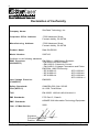
1
StorCase® Technology Data Silo® DS322 External FireWire-to-IDE Expansion Chassis User's Guide i StorCase® Technology Data Silo® DS322 External FireWire-to-IDE Expansion Chassis User's Guide Part No. D89-0000-0201 A02 January 2003 StorCase Technology, Inc. 17600 Newhope Street Fountain Valley, CA 92708-9885 Phone (714) 438-1850 Fax (714) 438-1847 DS322 User's Guide - Rev. A02 StorCase Technology, Inc. ii LIMITED WARRANTY STORCASE TECHNOLOGY, Incorporated (StorCase) warrants that its products will be free from defects in material and workmanship, subject to the conditions and limitations set forth below. StorCase will, at its option, either repair or replace any part of its product that proves defective by reason of improper workmanship or materials. Repair parts or replacement products will be provided by StorCase on an exchange basis, and will be either new or reconditioned to be functionally equivalent to new. This warranty does not cover any product damage that results from accident, abuse, misuse, natural or personal disaster, external power surge or failure, or any unauthorized disassembly, repair or modification. StorCase will not be responsible for any software, firmware or other customer data stored within, or interfacing with a StorCase product. Duration of Warranty Seven-Year Warranty: The following StorCase products are covered by this warranty for a period of seven (7) years from the original date of purchase from StorCase or its authorized reseller: all Data Express® removable device enclosures and all StorCase interface cables and accessories specifically intended for use with these products. Data Silo®, Data Stacker® and InfoStation® products are covered by this warranty for a period of seven (7) years, excepting the RAID controller, power supply, fan and blower components, which are covered by the three-year warranty described below. Three-Year Warranty: The following StorCase products are covered by this warranty for a period of three (3) years from the original date of purchase from StorCase or its authorized reseller: all Rhino®JR external expansion chassis, all RhinoJR removable drive enclosures, and all RAID controller modules. In addition, the following components of the Data Express, Data Silo, Data Stacker, InfoStation products are subject to warranty for a period of three (3) years: all power supplies, fans and blowers. Warranty Claim Requirements To obtain warranty service, the defective product must be returned to your local authorized StorCase dealer or distributor, or, with prior StorCase approval, to the StorCase factory service center. For defective products returned directly to StorCase, a Return Material Authorization (RMA) number must be obtained by calling StorCase Customer Service at (714) 445-3455. The RMA number must be prominently displayed on the outside of the return package. Shipments must be freight-prepaid and insured, and must include the product serial number, a detailed description of the problem experienced, and proof of the original retail purchase date. Products must be properly packaged to prevent damage in transit. Damage resulting from improper packaging will not be covered by this warranty. The StorCase factory service center is located at 17650 Newhope Street, Receiving Dock, Gate #4, Fountain Valley, CA 92780, U.S.A. StorCase Technology, Inc. DS322 User's Guide - Rev. A02 iii Free Technical Support StorCase provides free technical support. If you experience any difficulty during the installation or subsequent use of a StorCase product, please contact StorCases Technical Support Department prior to servicing your system. This warranty covers only repair or replacement of defective StorCase products, as described above. StorCase is not liable for, and does not cover under warranty, any costs associated with servicing and/or installation of StorCase products. StorCase Technical Support can be reached in the U.S. at (714) 438-1858 or toll-free at (888) 435-5460 (U.S. and Canada only). StorCase European Technical Support can be reached in the U.K. at +44 (0) 1932 738900. Disclaimers The foregoing is the complete warranty for the products identified above and supersedes all other warranties and representations, whether oral or written. StorCase expressly disclaims all warranties for the identified products, which are not stated herein, including, to the extent permitted by applicable law, any implied warranty of merchantability or fitness for a particular purpose. In no event will StorCase be liable to the purchaser, or to any user of a StorCase product, for any damages, expenses, lost revenues, lost savings, lost profits, or any other incidental or consequential damages arising from the purchase, use or inability to use a StorCase product, even if StorCase has been advised of the possibility of such damages. Copyright © 2003 StorCase Technology. All rights reserved. All registered trademarks are the property of StorCase Technology. All other logos and trademarks are properties of their respective companies. DS322 User's Guide - Rev. A02 StorCase Technology, Inc. iv Declaration of Conformity Company Name: StorCase Technology, Inc. Corporate Office Address: 17600 Newhope Street Fountain Valley, CA 92708 Manufacturing Address: 17600 Newhope Street Fountain Valley, CA 92708 Product Name: Data Silo DS322 Model Number: S30F103 Conforms to the following standards: EN 50081-1: 1992 Generic Emission EMC Directives: - EN 55022/CISPR22 Class A (89/336/EEC) - EN 61000-3-2 Harmonic Current - EN 61000-3-3 Voltage Fluctuations and Flicker EN 55024: 1998 ITE Immunity - IEC 61000-4-2 - IEC 61000-4-5 - IEC 61000-4-3 - IEC 61000-4-6 - IEC 61000-4-4 - IEC 61000-4-8 - IEC 61000-4-11 EN 60950 Low Voltage Directive: (73/23/EEC) Safety Standards: CSA (NRTL/C) CAN/CSA-C22.2 No. 950-95 UL 1950, Third Edition TUV: EN 60950: 1992+A1+A2+A3+A4+A11 EMI Standards: FCC Part 15, Class A EMC Standards: AS/NSZ 3548 Information Technology Equipment Year of Manufacture: 2002 Signature:___________________ Full name: Dieter Paul Position: President StorCase Technology, Inc. DS322 User's Guide - Rev. A02 v Important Safety Instructions 1. Read all these instructions. 2. Save these instructions for later use. 3. Follow all warnings and instructions marked on the product. 4. Do not use this product near water. 5. This product should be operated from the type of power source indicated on the marking label. If you are not sure of the type of power available, consult your dealer or local power company. 6. Do not attempt to service this product yourself, as opening or removing covers may expose you to dangerous voltage points or other risk. Refer all servicing to service personnel. Wichtige Sicherheitshinweise 1. Diese Hinweise sollten vollständig durchgelesen werden. 2. Diese Hinweise für einen späteren Gebrauch aufbewahren. 3. Allen auf dem Gerät angebrachten Warnungen und Hinweisen folgen. 4. Das Gerät nicht in der Nähe von Wasser verwenden. 5. Das Gerät nur mit dem Aufkleber bezeichneten Netzspannung betreiben. Bei Fragen über die Art der Netzspannung sollte der Händler oder das Energieversorgungsunternehmen zu rate gezogen werden. 6. Nicht versuchen das Produkt selbst zu reparieren. In allen Produkten existieren gefährliche elektrische Spannugen. Nicht das Gehäuse öffnen. 7. Wartungsarbeiten nur von qualifiziertern Kundendienstpersonal ausführen laßen. DS322 User's Guide - Rev. A02 StorCase Technology, Inc. vi Table of Contents INTRODUCTION ..................................................................................................................... Packaging Information .................................................................................................. Serial Number ................................................................................................................ General Description ...................................................................................................... Front Panel ............................................................................................................ Rear Panel ............................................................................................................. 1 1 1 2 4 6 INSTALLATION ...................................................................................................................... 8 Drive Preparation .......................................................................................................... 8 Drive Installation ................................................................................................... 9 Typical FireWire Configurations ................................................................................. 11 Typical Single Host Configurations ................................................................... 11 Typical Dual Host Configurations ...................................................................... 13 APPENDICES ........................................................................................................................ Appendix A - Specifications/Dimensions .................................................................. Appendix B - Optional Accessories .......................................................................... FireWire Cables .................................................................................................. Drive Carrier ........................................................................................................ Carrying Case ..................................................................................................... 15 16 18 18 19 20 Reader's Comments ............................................................................................................ 21 StorCase Technology, Inc. DS322 User's Guide - Rev. A02 vii List of Figures Figure 1: Figure 2: Figure 3: Figure 4: Figure 5: Figure 6: Figure 7: Figure 8: Figure 9: Figure 10: Data Silo DS322 .............................................................................................. 2 DS322 Front Panel .......................................................................................... 5 DS322 Rear Panel .......................................................................................... 6 Enlarged View of the FireWire Interface ...................................................... 7 Drive Installation Assembly ............................................................................ 9 Drive Cover Installation ................................................................................ 10 Typical Single Host Connection to One Data Silo ....................................... 11 Typical Single Host Connection to Multiple Data Silos ................................ 12 Typical Dual Host Connection to One Data Silo .......................................... 13 Typical Dual Host Connection to Multiple Data Silos .................................. 14 Figure Figure Figure Figure DS322 Physical Dimensions ........................................................................ FireWire Cables ............................................................................................ DE110 Drive Carrier ..................................................................................... Carrying Case ............................................................................................... A-1: B-1: B-2: B-3: 17 18 19 20 NOTICE: This User's Guide is subject to periodic updates without notice. While reasonable efforts have been made to ensure accuracy of this document, StorCase Technology, Inc. assumes no liability resulting from errors or omissions in this publication, or from the use of the information contained herein. Please check the StorCase web site at http://www.storcase.com or contact your StorCase representative for the latest revision of this document. DS322 User's Guide - Rev. A02 StorCase Technology, Inc. Introduction 1 INTRODUCTION Packaging Information The StorCase Technology Data Silo® external expansion chassis is shipped in a container designed to provide protection and prevent damage during shipment. The Data Silo was carefully inspected before and during the packing procedure at the factory. Evidence of any damage to the Data Silo should be reported to the shipper immediately. If the wrong Data Silo model has been received, please call your reseller or StorCase at (800) 435-0642 to arrange for a Return Material Authorization (RMA). StorCase cannot accept returns which do not display an RMA number on the outside of the package. Return the unit with all the original packing materials. Before removing any component from its packaging, discharge any static electricity by touching a properly grounded metal object. Serial Number The Data Silo is labeled with a serial number. This number must be reported to the StorCase Customer Service Representative in order to receive a Return Material Authorization (RMA) for warranty claims. Locate the serial number label and record the number in the space provided below. Serial Number: DS322 User's Guide - Rev. A02 StorCase Technology, Inc. 2 Introduction General Description WARNING: The DS322 contains NO USER SERVICEABLE PARTS inside the unit. Refer ALL servicing to qualified service personnel! The StorCase Technology Data Silo® DS322 2-bay expansion chassis with FireWire (IEEE-1394) interface and Data Express® DE110 removable drive enclosures provide durable and reliable mounting for two (2) 3.5" form factor, low-profile (1" high) Ultra ATA/100 drives. It is downward compatible with earlier technology IDE drives. The DS322 is available in a 2U rack mount, dual bay configuration (Figure 1). Each chassis is constructed of rugged steel and is equipped with one (1) 65W auto-ranging power supply, chassis status LED, two (2) adjustable-speed blowers, and all necessary internal wiring and drive mounting hardware. The DS322 comes standard with two (2) dual port FireWire (IEEE-1394) interfaces, which allow for single or dual host configurability. 320FW_1 Figure 1: Data Silo DS322 StorCase Technology, Inc. DS322 User's Guide - Rev. A02 Introduction 3 This User's Guide describes the steps required for installing drive(s) into the Data Silo external expansion chassis. This guide is intended to supplement documentation provided with the host computer system, the operating system, and the drive(s) to be installed within the Data Silo. Features: 2U rack mount enclosure Includes two (2) Data Express® DE110 removable IDE drive carriers and receiving frames Supports Ultra ATA/100 drives (downward compatible with earlier-technology AT/IDE drives) Supports drive hot swapping Two (2) FireWire (IEEE-1394) interfaces with multiple drive configurability Universal Plug and Play Supports FireWire high-speed transfer rates (up to 400Mbps) Compliant with ATA-5 and IEEE-1394 Standards Supports Microsoft® Windows® 98SE/2000/ME and Mac® OS generic SBP-2 drivers Corrosion-resistant steel construction Two (2) dual-speed blowers (11.3 CFM each) One (1) 65W auto-ranging power supply Audible alarm Includes external 10' and 20" FireWire cables Ideal for video editing Optional RAID Tool Kit software CD for Mac® OS 7-year warranty and free 24/7 technical support DS322 User's Guide - Rev. A02 StorCase Technology, Inc. 4 Introduction Front Panel (Figure 2) Data Express® DE110 Removable Drive Carrier(s) and Receiving Frame(s) Provides durable and reliable mounting for low-profile 3.5" Ultra ATA/100 drives (downward-compatible with earlier technology IDE drives). Unit ID Number and Activity Indicator(s) - Display the physical address of the DE110 device carrier if the carrier is Installed and Locked into the receiving frame or if the carrier is removed from the receiving frame. If the carrier is Installed but not Locked in the receiving frame, a "u" will be displayed to indicate an unlocked condition. The unit ID number is factory-set to "0" on both DE110 receiving frames. A small dot next to the unit ID number illuminates to indicate when the host computer is accessing the data on the DE110 carrier. This dot will flash during communication with the host computer. Key Lock/Drive Power Switch(es) - Perform three functions. The key switch assures proper seating of the drive carrier within the receiving frame, turns power to the drive on and off, and prevents unauthorized removal or installation of the carrier. NOTE: Disable FireWire device on host computer desktop before turning OFF power (simply right-click on FireWire Icon located in the System Tray and "disconnect"). Chassis Status LED/Audio Indicator - Provides the following operating information: Green = Power ON Flash Red = Fan Failure (alarm will sound) Chassis Handle(s) - Provide a sturdy grip for the installation and removal of the rackmount chassis. Power Switch - Rocker switch controls power to the DS322 chassis. StorCase Technology, Inc. DS322 User's Guide - Rev. A02 Introduction 5 Chassis Status LED Key Lock DE110 Removable DriveCarrier Chassis Handle 320FW_2 Power Switch DE110 Receiving Frame Unit ID Number and Activity Indicator Figure 2: DS322 Front Panel DS322 User's Guide - Rev. A02 StorCase Technology, Inc. 6 Introduction Rear Panel (Figures 3 & 4) FireWire Interfaces - Connect to a FireWire (IEEE-1394) device via FireWire cable (provided). Dual connectors allow for single or dual host configurability. Refer to section "Typical FireWire Configurations" for further information. Blower(s) - Two (2) blowers provide ample chassis ventilation (11.3 CFM each). Blower Speed Selector Switch - High and low speed. High speed (factorydefault) is recommended for high performance (10K RPM and higher) drives. A/C Power In - Accepts U.S. and other available international standard power cords. Blower Speed Selector Switch FAN H FireWire Interface L 320FW_3 Ground Stud A/C Power In Blower Vent Figure 3: DS322 Rear Panel StorCase Technology, Inc. DS322 User's Guide - Rev. A02 Introduction 7 FireWire Port (2) FireWire Port (1) 320FW_5 Figure 4: Enlarged View of the FireWire Interface DS322 User's Guide - Rev. A02 StorCase Technology, Inc. 8 Installation INSTALLATION CAUTION: The DS322 chassis contains NO USER SERVICEABLE parts inside the unit. Refer ALL servicing to qualified personnel! NOTE: Refer to the Data Silo DS322 User's Guide and Data Express DE110 User's Guide for additional operating and installation information. Also refer to the disk manufacturer's documentation for specific information regarding the disks. Drive Preparation NOTE: 1. Remove the drive from its protective packaging. 2. Plastic Drive Bezel: If the drive came equipped with a plastic front bezel, it must be removed before installing the drive into the drive carrier. 3. In most cases, your drive will be factory-configured as a Master Drive using a jumper option on the drive itself. StorCase however, recommends reconfiguring the drive to Cable Select instead. This can be done by configuring the jumper option on the drive itself (refer to the drive manufacturer's documentation for further information). Since specifications (specifically, pin assignments) between drive manufacturers may vary, please refer to your drive manufacturer's documentation for exact information regarding Cable Select configuration. StorCase Technology, Inc. DS322 User's Guide - Rev. A02 Installation 9 Drive Installation 1. Attach the DC power cable (from the Drive Carrier Board) to the drive (Figure 5). 2. Carefully insert the drive into the carrier. Slide the drive towards the Drive Carrier Board, so that the I/O connector on the drive mates with the connector on the Drive Carrier Board (Figure 5). Make sure that the DC power cable is not pinched. 3. Fasten the drive into place with four (4) #6-32 Phillips Flat Hd. screws (Figure 5). 4. Install the provided drive cover (Figure 6). Drive (Not Included) DC Power Cable Drive Carrier Board Drive Carrier 0835 #6-32 Phillips Flat Hd. Screw (4 each) Figure 5: Drive Installation Assembly DS322 User's Guide - Rev. A02 10 Installation 1 Insert this end into the carrier first 2 Slide the cover towards the back of the carrier 3 Secure with #6-32 Phillips Flat Hd. screws (2 Total) 0836 Figure 6: Drive Cover Installation 5. The DE110 drive carrier is now ready to be inserted into the receiving frame. NOTE: 6. The lock on the DE110 carrier functions as a lock and a DC power switch for the carrier unit. The lock must be engaged in order to supply power to the carrier and installed drive. Reboot the computer. The new disks is now ready for use, although it may have to be formatted or initialized prior to use with your operating system and applications software. WARNING: Unlocking the carrier unit switches DC power OFF to the drive. Since disk drives require a short amount of time to spin down, allow about 15 seconds before pulling the carrier unit out of the receiving frame to avoid possible damage to the drive. NOTE: Disable FireWire device on host computer desktop before turning OFF power (simply right-click on FireWire Icon located in the System Tray and "disconnect"). StorCase Technology, Inc. DS322 User's Guide - Rev. A02 Installation 11 Typical FireWire Configurations NOTES: The installation, configuration, and use of the StorCase Data Silo DS322 FireWire-IDE chassis requires a certain level of expertise and experience on the part of the user/integrator. Since there are many configuration options and variables (ie. host platforms, applications, etc), only general/ typical configuration guidelines will be discussed in this User's Guide. One (1) 10' FireWire cable and one (1) 20" FireWire cable are provided with each DS322 FireWire-IDE chassis. Typical Single Host Configurations NOTE: Depending on configuration, additional FireWire cabling may be required. Contact StorCase for further ordering information. 20 FireWire Cable (Provided) 10 FireWire Cable (Provided) 320FW_8 FireWire Host Figure 7: Typical Single Host Connection to One Data Silo DS322 User's Guide - Rev. A02 12 Installation 20 FireWire Cable (Provided) 10 FireWire Cable (Provided) FireWire Host 10 FireWire Cable (Provided) 20 FireWire Cable (Provided) 320FW_9 Figure 8: Typical Single Host Connection to Multiple Data Silos StorCase Technology, Inc. DS322 User's Guide - Rev. A02 Installation 13 Typical Dual Host Configurations NOTE: Depending on configuration, additional FireWire cabling may be required. Contact StorCase for further ordering information. FireWire Cable (Optional) FireWire Host 10 FireWire Cable (Provided) 320FW_10 FireWire Host Figure 9: Typical Dual Host Connection to One Data Silo DS322 User's Guide - Rev. A02 14 Installation 10 FireWire Cable (Provided) FireWire Host 10 FireWire Cable (Provided) FireWire Host 20 FireWire Cable (Provided) 20 FireWire Cable (Provided) 320FW_11 Figure 10: Typical Dual Host Connection to Multiple Data Silos StorCase Technology, Inc. DS322 User's Guide - Rev. A02 Appendix A - Specifications/Dimensions 15 APPENDICES DS322 User's Guide - Rev. A02 StorCase Technology, Inc. 16 Appendix A - Specifications/Dimensions Appendix A - Specifications/Dimensions The following DS322 specifications and dimensions are provided for reference only. 0 C to 40 C -40 C to 70 C -1000 to 10,000 ft -1000 to 40,000 ft -305m to 3048m -305m to 12195m IEEE-1394 & Compliance ATA-5 3.35 (85.1mm) 16.92 (429.8mm) 14.00 (355.6mm) Max. Transfer Rate up to 400Mbps Max. Cable Length 4.5m (14.75 ft) 20.0 lbs (9.1kg) Total weight including 2 DE110s (1) Auto Ranging 65 Watt (112W Peak*) Power Supply 100VAC - 240VAC, 50-60Hz DC Output Continuous * 5 sec. maximum Total for 2 Blowers (High Speed) 22.6 CFMs 320FW_specs StorCase Technology, Inc. DS322 User's Guide - Rev. A02 Appendix A - Specifications/Dimensions 17 16.92 (429.8mm) 14.00 (355.6mm) Top View 1.04 (26.4mm) Front View Right Side View 3.35 (85.1mm) 320FW_dims 19.00 (482.6mm) 1.18 (30.0mm) Figure A-1: DS322 Physical Dimensions (Dimensions are for reference only) DS322 User's Guide - Rev. A02 StorCase Technology, Inc. 18 Appendix B - Optional Accessories Appendix B - Optional Accessories FireWire Cables (Figure B-1) Additional FireWire cables are available for the DS322. Contact StorCase for further ordering information. 10ft. FireWire Cable 20in. FireWire Cable 4FW_8 Figure B-1: StorCase Technology, Inc. FireWire Cables DS322 User's Guide - Rev. A02 Appendix B - Optional Accessories 19 Drive Carriers (Figure B-2) Additional DE110 removable drive carriers are available for the DS322 as shown in Figure B-2. Contact StorCase for further ordering information. 320FW_12 Figure B-2: DE110 Drive Carrier DS322 User's Guide - Rev. A02 StorCase Technology, Inc. 20 Appendix B - Optional Accessories Carrying Case (Figure B-3) The optional molded plastic carrying case (P/N S20E101) is designed to transport the DE110 drive carrier from one site to another in a safe, impact and moisture resistant environment. Its compact dimensions, 7" long x 9" wide x 4" high, make it easy to carry and store. The foam lining is contoured to fit a single DE110 carrier. Contact StorCase for further ordering information. 320FW_13 Figure B-3: Carrying Case StorCase Technology, Inc. DS322 User's Guide - Rev. A02 Reader's Comments 21 Reader's Comments Please take a few moments when your computer system is up and running to send us your ideas and suggestions for improving our products and documentation. Did the installation go smoothly for you? Are there any changes you would like us to make, either with the hardware itself, or with the installation instructions? Everyone at StorCase Technology is working toward the goal of providing you with the highest quality, most cost effective, products available on the market, and we need your comments to guide our efforts. We look forward to hearing from you soon! Date: Your Name: Address: Telephone: ( ) To mail this page, carefully remove it from the manual, fold it, staple or tape it shut, and drop it in the mail. To FAX this page, carefully remove it from the manual (or make a photocopy) and FAX it to us at (714) 438-1847. Thank you for taking the time to help us make our products better! DS322 User's Guide - Rev. A02 StorCase Technology, Inc. Reader's Comments CUT ALONG THIS LINE FROM BOTTOM TO TOP OF PAGE 22 FOLD ALONG THIS LINE AND STAPLE SHUT NO POSTAGE NECESSARY IF MAILED IN THE UNITED STATES B U S I N E S S R E P LY M A I L FIRST CLASS MAIL PERMIT NO. 10686 SANTA ANA, CA POSTAGE WILL BE PAID BY ADDRESSEE TECHNOLOGY CORPORATION 17600 NEWHOPE STREET FOUNTAIN VALLEY CA 92708-9885 StorCase Technology, Inc. DS322 User's Guide - Rev. A02