1
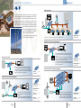
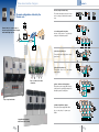
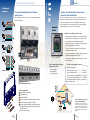
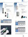
Catalogue
Inverter-chargers
Battery monitoring
Engineered power
Inverters
Battery chargers
Battery splitters
Battery separators
DC/DC converters
SWISS made power
Company
Summary
Experience and competences
The company Applications
3
6
- Applications in remote areas
6
- Mobile applications
8
- Backup applications
10
Products
In 2005, the Sommet Prize, organized
among others by the Union Bank of Switzerland was awarded to Studer Innotec,
for its capabilities to innovate as well as
to export its inverters.
12
- Sine wave inverter-chargers 12
- Sine wave inverters
20
- Battery chargers 24
- DC/DC converters 25
- Battery splitters
26
- Battery separators 26
- Battery protection 27
- Battery monitoring 27
Appendices
Studer Innotec was founded in 1987 by
Roland Studer, current General Director.
From 1987 to 1991, the company developed its areas of competences in the solar
photovoltaics and in the energy conversion, with the first inverters (DC/AC).
90% of the turnover exported
The launch in 1994 of the Twinpower, then in 1995 of the SI, both
sine wave inverters with unbeaten performances so far, makes Studer Innotec’s offer very attractive to demanding export
markets.
This is the start of an export business which represents now
some 90% of its turnover.
28
- Technical sheets
28
- How to find us 36
Photos credits
Robert Hofer : Studer’s products ; Perspective : 4, 5, 24 ; Steca : p. 6 bottom ; Jeanneau : p. 8 top ;
Meteorisk : p. 3, 8, 36 ; Siblik: p. 21.
Graphism
Atelier Perspective, R. Gigon, Sion.
February 2009
2
3
Company
Leadership
Comfort and versatility of the products
Studer Innotec is today the leader of the inverter market in
Switzerland and in Europe, and a major actor in the rest of the
World.
In future, this choice for quality and for service will continue to
guide our strategic axes.
It employs 50 people and manages a network of more than one
hundred distributors in more than 70 countries.
Thanks to a large range of products, it is the only inverter manfacturer to cover the solar photovoltaic market as well as the
nautical, the mobile, the backup and the telecom markets.
Integration and flexibility of the production
The philosophy of the company has been, from the very beginning, to master the process from A to Z, so from the development to the sales of the products. This is why Studer Innotec has
started as a vertically integrated manufacturer, therefore more
flexible than its competitors.
Beyond the performances, the next inverters will provide more
comfort and will offer a greater versatility to their users.
Closeness to the clients
From research to industrial implementation, Studer Innotec intends to keep on investing financially and also in human resources, in order to maintain its lead in terms of the offer and of the
closeness to the clients. This closeness expresses itself also by a
network of partners qualified to service its products. The addresses of these partners, as well as the distributors, will be found
on the company’s website, under the heading « Distributors ».
In other respects, to turn the markets expectations into products
and services, an 8 people team is fully dedicated to Research &
Development.
The choice of the performance
The high-tech design of its products, as well as the choice of
the performance and of the reliability, brings Studer Innotec to
select its components with the highest care. This is the reason
why it has chosen the latest technologies, like the digital signal
processors (DSP) which provide better performances and a higher efficiency to its inverters.
4
5
Applications
Applications in remote areas
Village electrification
Far from any electrical grid, by choice or by force, security and
comfort (lighting, heating, household appliances, leisure electronics, telecoms…) can yet be provided by autonomous energy systems. These systems consist firstly of an energy source,
normally a genset, a solar generator, a wind turbine or a combination of them, secondly of a battery storage, and then thirdly of
devices (inverter-charger, battery charger)
able to charge the battery from this energy source and to supply the users with AC
voltage (inverter, inverter-charger).
GENERATOR
GRID
INVERTER
AC
GRID
INVERTER
DC
The examples below show the products
in some stand-alone applications.
Xtender serie p. 12
(1600 - 63000 VA)
Various power sources supply energy to several consumer points.
Hybrid system : more autonomy and flexibility
GENERATOR
AC
This hybrid system provides a great flexibility in supply
and an increased autonomy in relation to each source of
energy.
The AC voltage supply to the appliances is done directly
from the energy source through the transfer relay, or from
the battery through the inverter function.
The charger function allows to charging the battery with
the genset. The size of the genset can be reduced thanks to
the function Smart-Boost.
DC
DC
AC
A complete solar system
DC
AC
DC
This is a complete solar system that the combination
of the inverter and of the optional built-in solar charge
controller function allows to create. The inverter supplies
the appliances with AC voltage and charges the battery
with DC voltage from the solar generator.
Xtender serie p. 12
(1600 - 63000 VA)
Compact series p. 18
(1100 - 7000 VA)
3-phase grid 3 x 400Vac for high power appliances
AJ serie (200 - 2000 VA)
p. 20
AC
Quality AC voltage for all electrical appliances
GENERATOR
AC
DC
AC
REGULAT0R
DC
6
The inverter supplies, exclusively from a battery,
any kind of appliance using AC voltage, without
exception.
It does convert the battery DC voltage into AC voltage with a better quality than from the public grid.
DC
Compact series p. 18
(1100 - 7000 VA)
DC
DC
Xtender serie p. 12
(1600 - 63000 VA)
REGULATOR
AJ serie (200 - 2000 VA)
p. 20
SI serie (600 - 10500 VA)
p. 22
DC
A 3 x 400Vac 3-phase grid can be built with
3 inverters for the supply of high power
appliances. In case of an increased need of
power it is possible to set up to 3 inverters
in parallel on each phase (Xtender only).
7
Xtender serie p. 12
(1600 - 63000 VA)
SI serie (600 - 10500 VA)
p. 22
Applications
Mobile applications
3 x 400Vac 3-phase grid on-board
An energy system on-board is often necessary to power the
AC voltage users, while the vehicle or the boat is away from the
electrical grid (port, garage, camping…). In that case the energy
is stored in the battery, which is actually charged by power sources on-board, like genset, solar generator, wind turbine, alternator or a combination of them. Studer Innotec offers the range
of products that secure the management and the conversion of
this energy, while securing an optimal supply of the appliances on-board.
AC
AC
DC
DC
A 3-phase grid can be built with 3 inverters. The serie Xtender
enables to create a 3-phase grid and to charge simultaneously the
battery, even if only a single phase is available as a power source
Xtender serie p. 12
(1600 - 63000 VA)
SI serie (600 - 10500 VA)
p. 22
Variable power source assistance
VARIABLE POWER
SOURCE
AC
AC
DC
The examples below show our products in
some mobile applications.
AC
The source being a variable power alternator, the Smart-boost will supply the power
difference in order that the power delivered
is always the same.
Xtender serie p. 12
(1600 - 63000 VA)
Successive charge of the batteries
A simple and reliable system on-board
AC
AC
DC
AC
AC
DC
DC
The inverter-charger charges the battery from the grid or
from a genset, and powers any kind of electrical appliance.
It converts the battery DC voltage to AC voltage.
DC
Xtender serie p. 12
(1600 - 63000 VA)
Compact series p. 18
(1100 - 7000 VA)
An upgradeable power
MBR serie p. 26
MBC serie p. 24
MBI serie p. 26
MBC serie p. 24
MOTOR
DC
DC
In this system, a battery
separator enables the charge of one or several auxiliary batteries once the primary battery is charged.
Simultaneous charge of batteries
MOTOR
AC
DC
AC
AC
DC
DC
AC
DC
DC
DC
DC
The power available for the users can be adapted in the
course of time by adding inverters in parallel or by creating
additional phases. It is therefore possible to install up to 9
inverters in a 3-phase power system.
8
Xtender serie p. 12
(1600 - 63000 VA)
A MOSFET splitter, with almost no voltage losses, enables to split the charge current to
and in between several batteries. From the battery pack, a DC/DC converter will step up or
step down the voltage according to the voltage of the users, 12, 24 or 48Vdc.
9
MDCI-MDC series p. 25
Applications
Backup applications
Uninterruptible power supply off-line
Powered by the public grid, the users like fridges, PCs, emergency lights, etc. which can not afford any power cut, are electrically
secured. An inverter-charger with transfer relay or a combination of an inverter and a charger guarantees to maintain well
the battery and to keep uninterrupted the supply of strategic appliances.
AC
DC
AC
In this configuration the grid supplies directly the users thanks
to the by-pass function of the inverter-charger. In case of a
drop or a cut of the grid, the inverter-charger guarantees the
supply of the users.
Studer Innotec offers solutions from 200W up to 63kW with a
product choice unchallenged on the market.
Some examples of backup applications are described below.
Xtender serie p. 12
(1600 - 63000 VA)
Compact series p. 18
(1100 - 7000 VA)
Individual Home backup
AC
An inverter-charger is
used there to provide a
backup power in case of
public grid outage. As
soon as the power shuts
off the inverter-charger
switches on inverter
mode and assures an
uninterruptible power
supply.
DC
AC
Xtender serie p. 12
(1600 - 63000 VA)
Compact series p. 18
(1100 - 7000 VA)
Solsafe – a backup system for grid connected solar installations
GRID
INVERTER
DC
Uninterruptible power supply on-line
Compteur
AC
AC
DC
DC
p. 20
AC
AJ serie (200 - 2000 VA)
DC
AC
SI serie (600 - 10500 VA)
Solsafe
S-Box
Secured
p. 22
p. 17
Not secured
In this system, the functions of battery charge and of users supply are separated, with
on one side a battery charger, and on the other an inverter. The fluctuations of the grid
current have no impact on the users.
10
MBC serie p. 24
The installation of our solution Solsafe in a grid connected solar system enables to secured
totally or partially the power supply in case of a power cut, and so to keep on using the solar
energy being produced.
11
Xtender serie p. 12
(1600 - 63000 VA)
Compact series p. 18
(1100 - 7000 VA)
Products
Applications
Sine wave inverter-chargers
Inverter
Xtender Series
The Xtender serie provides an unmatched freedom of use thanks to its
many functions. In a basic application, it offers together the functions of
inverter, battery charger, transfer system and assistance to the source.
These functions can be combined and controlled in a totally automatic
way for an exceptional comfort and an optimal management of the energy
available. Its programmable auxiliary contacts allow as well the interconnection with existing systems or the implementation of extended
functions.
Xtender
XTM
XTM 2000-12
XTM 3500-24
XTM 4000-48
Power
P30/Pnom
Power
Smart-Boost
Charge
current
Maximum
current
XTH 3000-12
12V
3000VA / 2500VA
3000VA
0 - 160A
50A / 11.5kVA
XTH 5000-24
24V
5000VA / 4500VA
5000VA
0 - 140A
50A / 11.5kVA
XTH 6000-48
48V
6000VA / 5000VA
6000VA
0 - 100A
50A / 11.5kVA
XTH 8000-48
48V
8000VA / 7000VA
8000VA
0 - 120A
50A / 11.5kVA
XTM 2000-12
12V
2000VA / 2000VA
2000VA
0 - 100A
50A / 11.5kVA
XTM 3500-24
24V
3500VA / 3000VA
3500VA
0 - 90A
50A / 11.5kVA
XTM 4000-48
48V
4000VA / 3500VA
4000VA
0 - 50A
50A / 11.5kVA
Complete technical specifications on page 28.
Smart-Boost function
• Parallel and 3 phase configuration up to 9 units.
The function Smart-Boost enables to add the inverter power to another
source, like for instance a genset or the shorepower, even in case of
complex (reactive, crest factor etc.) loads. This offers the possibility to
reduce the peak loads (power shaving) and to undersize the genset.
• Smart-Boost Function for assistance to the source.
• Automatic reduction of peak loads (power shaving).
Transfer
Battery
voltage
Xtender range
Features and performances
• Outstanding efficiency and overload capabilities.
Charger
Generator
or Grid
Charge
• Automatic allocation of the available power (power sharing).
Battery
• Standby level adjustable from a very low load threshold.
• Multi-stage, fully programmable battery charger with PFC.
Xtender
XTH
Wide modularity
• Ultra fast high power transfer relay.
By the implementation of several units, it is possible to create a
3-phase source or to set them in parallel to increase the power
available without extra cost. Up to 9 inverters of the Xtender serie
shall therefore be combined together up to 72 kW !
• Control by digital signal processor (DSP).
• 2 fully independently programmable auxiliary contacts.
XTH 3000-12
XTH 5000-24
XTH 6000-48
XTH 8000-48
Xtender
• Real time clock for event record and auxiliary relay programming.
Accessories
RCC-02
Comprehensive
LCD display
RCC-03
Remote control and programming centre RCC-02 with 2 m cable
For display, programming and updates purposes. Wall mounting.
Dimensions HxLxl : 170 x 168 x 43.5 mm.
Remote control and programming centre RCC-03 with 2 m cable
For display, programming and updates purposes. Panel mounting.
Dimensions : HxLxl : 130 x 120 x 42.2 mm.
Remote control and programming centre RCC-02 or RCC-03
Apart from the enclosure difference, adapted for wall or panel mounting,
both units have exactly the same features and allow the user to survey his system and fully customize it
to his needs. RCC gives a controlled access to the many adjustable parameters of the Xtender. It enables
the setting of the charge curve of the battery, the programming of the auxiliary contacts and gives access
to a lot of operation options. Thanks to its graphic display RCC provides clear and comprehensive indications on the state of the system in selectable language. The unit memorizes and displays the events that
occurred on an installation and so it does anticipate the problems that might appear. A slot for a SD card
is available and it allow the parameters record and download as well as the full software update.
12
Remote Control Module RCM-10. Only for XTM with 3 m cable (possible up to 5 m)
DIN rail remote module for main on/off and programmable function input.
Dimensions : HxLxl : 45 x 73 x 45 mm.
Battery temperature sensor BTS-01 with 3 m cable
This sensor enables to accurately adapt the charge thresholds to the battery temperature.
Dimensions : HxLxl : 58 x 51.5 x 22 mm.
Communication cable for 3ph and parallel CAB-RJ45-8-2 (2 m)
Allows the setting in parallel or the implementation of a 3-phase system.
13
Products
Sine wave inverter-chargers
The main configurations offered by the
Xtender serie
Inverter, charger and transfer relay
The Xtender basically works as an inverter
and as a charger, combined with a transfer
relay.
GENERATOR
XT
GENERATOR
GENERATOR
AC
AC
XT
XT
XT
XT
XT
XT
XT
XT
XT
XT
XT
GENERATOR
GENERATOR
GENERATOR
XT
XT
XT
XT
XT
XT
XT
GENERATOR
GENERATOR
GENERATOR
GENERATOR
GENERATOR
XT
XT
XT
XT
XT
XT
XT
XT
XT
XT
XT
XT
XT
XT
XT
GENERATOR
XT
XT
XT
XT
XT
XT
XT
GENERATOR
GENERATOR
GENERATOR
XT
XT
XT
GENERATOR
XT
GENERATOR
XT
GENERATOR
3 phase in and 3 phase out
Three-phase source for a three-phase
power supply.
XT
GENERATOR
XT
GENERATOR
GENERATOR
XT
XT
XT
XT
XT
XT
XT
XT
GENERATOR
GENERATOR
3 phase + with one reinforced phase
Three-phase power supply with increase
of the power on one phase by setting 2 or 3
Xtender in parallel on this phase.
XT
GENERATOR
GENERATOR
XT
GENERATOR
GENERATOR
GENERATOR
GENERATOR
GENERATOR
XT
XT
XT
XT
XT
XT
XT
XT
XT
XT
XT
XT
XT
XT
XT
XT
XT
XT
XT
XT
XT
XT XT
XT
XT
XT
XT XT
XT
XT
XT
XT XT
XT
XT
XT
GENERATOR
GENERATOR
XT
Compatible with standard
cable channel (230 x 60 mm)
14
XT
XT
XT
XT
3 Xtender in parallel on 3 phases
Three-phase power supply with 3 Xtender on each phase, for power up to
72kW.
XT
XT
XT
XT
GENERATOR
Easy set up of multi-units
XT
XT
XT
Easy accessible and robust
connections
XT
XT
GENERATOR
1 phase in and 3 phase out
Three-phase power supply from a single
phase source.
XT
XT
GENERATOR
DC
XT
XT
GENERATOR
REGULAT0R
XT
XT
GENERATOR
GENERATOR
XT
GENERATOR
GENERATOR
2 or 3 units in parallel on 1 phase
Increase of the power on one phase by
setting 2 or 3 Xtender in parallel.
XT
XT
GENERATOR
GENERATOR
Xtender family is a complete range of
inverter-chargers ideally suited for hybrid,
mobile and backup systems.
XT
GENERATOR
15
XT
XT
XT
XT
XT
XT
XT
XT
XT
XT
XT
XT
XT
XT
XT
XT
XT
XT
XT
XT
XT
XT
X-Connect
system
Pre-wired mounting frame for Xtender
multi-system
XT
XT
XT
XT
XT
XT
XT
XT
XT
XT
XT
XT
GENERATOR
XT
Centralized
GENERATOR
Solsafe : the anti-blackout system for grid
connected solar installations
Offers a flexible and cost effective solution for high power systems
based on XTH inverter
GENERATOR
GENERATOR
GENERATOR
Products
Applications
Sine wave inverter-chargers
XT
XT
Solsafe
S-Box
Despite a solar system on your house, in case of power outage, the
grid inverters will shut off and the solar generator, whatever its size,
will be useless. Studer Innotec has developped, already in 2004, a
concept in which its inverter-chargers allow to keep energy available
from the solar generator, even in case of a power cut.
GENERATOR
XT
XT
XT
Compared to other similar solutions, it offers :
GENERATOR
GENERATOR
XT
XT
XT
XT
XT
XT
•
Parallell
XT
XT
GENERATOR
XT
XT
XT
GENERATOR
XT
XT
XT
GENERATOR
GENERATOR
XT
XT
XT
XT
• The choice of the grid inverter allowing to work with
standard well known products
3-phase
XT
XT
XT
XT
XT
XT
XT
XT
XT
XT
XT
XT
XT
XT
XT
XT
XT
XT
XT
XT
XT
XT
XT
XT
XT
XT
XT
XT
XT
XT
XT
XT
Parallell + 3-phase
XT
XT
XT
XT
• To choose the grid inverter with any voltage input range,
independently from the battery voltage
• A possible and easy upgrade of existing grid-connected
solar installations
GENERATOR
GENERATOR
GENERATOR
GENERATOR
7
91
A great system flexibility by choosing independently the
grid inverter power (matching the solar generator) and
the stand-alone power (matching the needs for
autonomous energy), so long the stand-alone inverter is
as big or bigger than the grid inverter
S-Box : a genuine cabling solution to
implement the Solsafe
The S-Box can be supplied in 4 versions :
For single phase application :
• Hassle free cabling
- Solsafe box 25A for Compact………………......S-Box-25C
• Quick installation
- Solsafe box 25A for Xtender…………………....S-Box-25X
• Easy commissioning
mm
- Solsafe box 25A for Compact with ENS-26......S-Box-25C-E
- Solsafe box 25A for Xtender with ENS-26........S-Box-25X-E
For Solsafe implementation in 3ph systems, a schematic is at
disposal on simple request.
Up to 72kW multi-unit system
2
1
3
3x
9x
5
Pre-installed DC circuit breakers
2
Pre-installed DC fuses
3
Pre-installed DIN rails
4
Interconnection pipes and gland for auxiliary contact wiring
5
Interconnection pipes and gland for AC wiring
6
Interconnection pipes and gland + 90 mm2 wire terminated
with appropriates ring tongues for DC wiring from Xtender
to breakers and fuses
6
Screws set for frame assembly
3x
16
AC
Solsafe – a backup system for grid
connected solar installations
AC
4
1
GRID
INVERTER
DC
DC
981 mm
Frame is supplied with :
The installation of our solution Solsafe
in a grid connected solar system enables
to secured totally or partially the power
supply in case of a power cut, and so to
keep on using the solar energy being
produced.
Secured
Not secured
17
Products
Applications
Sine wave inverter-chargers
Multifunctional contact
The 16 A. potential free contact can be programmed according to the user wishes. It can react according
to the battery levels as well as to the system status (alarm conditions, presence of the public grid, sunlight’s presence…), and it enables for example :
The models of the Compact series consist of 3 fully automatic functions :
a sine wave inverter, a battery charger and a transfer system. Equiped
with a high-end technology, they carry our long experience in the field of
electrical supply.
1/ Automatic disconnection of
second priority users (condi tional supply).
Features and performances
2/ Alarm signalisation, acoustic
signal, MODEM, radio alarm etc.
• True sine wave voltage.
3/ Conditional battery charge.
GENERATOR
AC
DC
3
2
AC
AC
DC
1
AC
DC
Compact series
• Suitable for any kind of electrical appliance.
• Reliable and silent working with all kind of loads.
XP COMPACT
• Outstanding overload capabilities.
XPC 1400-12
XPC 2200-24
XPC 2200-48
• Stand-by level adjustable over a large range and from
a very low threshold.
• 4 STEP battery charger with PFC.
• Ultra-fast transfer relay.
• High efficiency.
COMPACT
Accessories
XP COMPACT
COMPACT
HP COMPACT
Remote control RCC-01
Comprehensive LED display. Also for the programming of
the COMPACT series (supplied with 20m cable).
l
l
l
Temperature sensor CT-35
This sensor adapts charge levels to the temperature variations of the battery (supplied with 3m cable).
l
l
l
l
l
l
• Full internal protection.
C 1600-12
C 2600-24
C 4000-48
• Ultra-fast regulation.
• Microprocessor controlled.
Remote control RPS-01
The setting of the power sharing can be remotely
controlled by means of the remote control supplied with a
20m cable.
HP COMPACT
Norm E certification
The XPC 1400-12, XPC 2200-24, C 1600-12 and
C 2600-24 are certified to the ECE-R 10 norm. This
certification is mandatory in the European Union
for all electrical equipments on board of vehicles.
Function inverter
Function charger
Transfer relay
Auxiliary relay module ARM-01
Equiped with 4 programmable relays, this module enables
to implement the system Solsafe (see page 11).
l
l
Cover CFC-01
This cover provides an additional protection to the connections by means of glands.
l
l
Cover C-IP23
Cover for a protection against intrusions or projections,
installed after the mounting of the device. It extends the
protection index from IP 20 to IP 23.
l
l
Compact range
Power 30 min. /
continuous at 25°C
Battery voltage
Adjustable charge
current
Maximum current
XPC 1400-12
1400VA / 1100VA
12Vdc
0 - 45A
16A/3.7kVA
XPC 220O-24
2200VA / 1600VA
24Vdc
0 - 37A
16A/3.7kVA
XPC 2200-48
2200VA / 1600VA
48Vdc
0 - 20A
16A/3.7kVA
C 1600-12
1600VA / 1300VA
12Vdc
0 - 55A
16A/3.7kVA
Optional built-in solar charge controller (-S)
C 2600-24
2600VA / 2300VA
24Vdc
0 - 55A
16A/3.7kVA
C 4000-48
4000VA / 3500VA
48Vdc
0 - 50A
16A/3.7kVA
HPC 2800-12
2800VA / 2500VA
12Vdc
0 - 110A
30A/6.9kVA
HPC 4400-24
4400VA / 4000VA
24Vdc
0 - 100A
30A/6.9kVA
HPC 6000-48
6000VA / 5000VA
48Vdc
0 - 70A
30A/6.9kVA
HPC 8000-48
8000VA / 7000VA
48Vdc
0 - 90A
50A/11.5kVA
The models XP Compact and Compact are
available with an optional built-in charge
controller (I/U/Uo) making the invertercharger an « all in one » device for a solar
installation.
DC
Complete technical specifications on page 29.
18
AC
DC
HPC 2800-12
HPC 4400-24
HPC 6000-48
HPC 8000-48
19
Products
AJ serie
Options and accessories
The AJ range consists of sine wave inverters that convert the DC
voltage of a battery into AC voltage which can be used by all electrical
appliances.
• High and steady efficiency.
AJ 1000-12, AJ 1300-24
AJ 2100-12, AJ 2400-24
Remote control JT8
Enables to control the inverter remotely
(supplied with 10m cable).
l
Plug for remote control RCM :
RCM 01 : ON when a contact is closed ;
RCM 02: ON when a voltage is present (key controlled) on the
remote control ;
RCM 03 : ON when a contact is open.
Features and performances
l
• Outstanding overload capabilities.
AJ serie
• Digital regulation and control by microprocessor.
AJ 275-12
AJ 350-24
AJ 400-48
• Electrical supply to any kind of appliance.
• Full internal protection.
• Stand-by level adjustable from a very low threshold.
AJ serie
AJ 500-12
AJ 600-24
AJ 700-48
AJ serie
DC
Optional built-in solar charge controller (-S)
An optional 3 STEP charge controller
(I/U/Uo) can be supplied built-in making
the inverter AJ an « all in one » device for a
solar installation.
AC
Norm E certification
AJ 1000-12
AJ 1300-24
The AJs in 12 and 24Vdc are certified to the ECE-R
10 norm. This certification is mandatory in the
European Union for all electrical equipments on
board of vehicles.
AJ serie
AJ 2100-12
AJ 2400-24
Battery
voltage
AJ 275-12
275VA / 200VA
12Vdc
AJ 350-24
350VA / 300VA
24Vdc
AJ 400-48
400VA / 300VA
48Vdc
AJ 500-12
500VA / 400VA
12Vdc
AJ 600-24
600VA / 500VA
24Vdc
AJ 700-48
700VA / 500VA
48Vdc
AJ 1000-12
1000VA / 800VA
12Vdc
AJ 1300-24
1300VA / 1000VA
24Vdc
AJ 2100-12
2100VA / 2000VA
12Vdc
AJ 2400-24
2400VA / 2000VA
24Vdc
Rural electrification (Solar Home System)
The rural electrification and the inverters of the AJ serie : excellence to the benefit of the development
of remore areas and populations. Choosing AC voltage for the rural electrification systems is going
for simplicity, reliability and cost saving. Indeed, compared with a DC voltage one, a system with an
inverter is often more efficient from 100W of solar power, and is always since 200W.
The AJ serie, due to its overload
capability and to its very reliable stand-by system adjustable
from 1W, is the most suitable
range of inverters to meet the
rural electrification technical
and economical requirements.
AC
DC
Power 30 min. /
continuous at 25°C
AJ range
AJ 275-12, AJ 350-24
AJ 400-48, AJ 500-12
AJ 600-24, AJ 700-48
DC
Applications
Sine wave inverters
Complete technical specifications on pages 30-31.
20
21
Products
Applications
Sine wave inverters
Options and accessories
SI serie
• Outstanding overload capabilities thanks to the combi ned use of a toroidal transformer, of an oversized
power stage and of an ultra-fast regulation.
SI serie
SI 612
SI 624
SI 648
SI 812
SI 824
SI 1212
SI 1224
SI 1248
SI 1624
SI 2324
SI 2348
SI 3324
SI 3548
l
Option 19’’ SI xxxxIND, inverter in 19’’ rack.
l
Alarm contact SI xxxxA, potential free contact 60V/0.5A.
l
Solar charge controller SI xxxS, built in the SI, 16A max. current.
l
• Full internal protection.
From 1200W there is a possible choice between
a stand-by system (load detection adjustable
from 0.3 to 20W) and the unique TWINPOWER
option.
• Possibility in option to connect 3 inverters together in
an autonomous 3 x 400Vac 3-phase grid.
SI serie
Option 3-phase SI xxxxPE, for 3 x 400V applications.
Option TWINPOWER
• Reliable and silent working with all kind of loads.
• Built-in solar charge controller in option for solar
systems (only SI 600 and 800).
l
100
90
80
The TWINPOWER option enables the permanent use of very small loads (like alarms
or security systems) with an
outstanding efficiency, 10 times
100
90
higher than any other inverter,
80
and a no-load consumption
70
60
< 0.5W (see above Options and
50
40
accessories).
Efficiency (%)
• A range in 19’’ rack is also available from 1200 to 3500W
(see option SIxxxxIND).
l
l
• Electrical supply to any kind of appliance.
• Stand-by level adjustable over a large range and from
a very low threshold.
l
Option Twinpower SI xxxxTP, without stand-by, no-load consumption < 0.5W.
Efficiency (%)
• High efficiency.
SI 1212 and up
Cover C-IP23
Cover for a protection against intrusions or projections, installed
after the mounting of the device. It extends the protection index
from IP 20 to IP 23.
The SI range consists of sine wave inverters that convert the DC voltage of
a battery into AC voltage which can be used by all electrical appliances.
Features and performances
SI 612 to SI 824
70
60
50
40
30
20
10
0
20
40
60
80
100
30
20
10
0
SI range
Continuous power
at 25°C
Battery voltage
SI 612
600VA
12Vdc
SI 624
600VA
24Vdc
SI 648
600VA
48Vdc
SI 812
800VA
12Vdc
120
140
160
180
Power (% de Pnom)
5
10
15
20
25
Power (W)
30
35
40
45
50
SI + Twinpower
SI
Conventional
Industrial casing in 19’’ rack
800VA
24Vdc
1200VA
12Vdc
SI 1224
1200VA
24Vdc
SI 1248
1200VA
48Vdc
SI 1624
1600VA
24Vdc
SI 2324
2300VA
24Vdc
SI 2348
2300VA
48Vdc
SI 3324
3300VA
24Vdc
SI 3548
3500VA
48Vdc
AC
3-phase
DC
SI 824
SI 1212
The availability of the inverters in 19’’ rack, from the SI 1200,
is a direct evolution of the sine wave SI series and it meets
particularly well the industrial applications (see above Options and accessories).
With the PE option, and from the SI 1200, it is possible to
connect 3 inverters together to build a 3 x 400Vac 3-phase
grid. This extends the SI range up to 10500VA (3 x SI 3548
PE). Such a configuration enables to supply motors and other
3-phase equipments, even with asymetrical powers on the
phases (see above Options and accessories).
Complete technical specifications on page 32.
22
23
L1
L2
L3
N
Products
DC/DC converters
Battery chargers
MBC serie
MDCI and MDC series
The MBC chargers enable to charge a battery from an AC voltage
source of supply (genset, public grid, shore power...). These chargers are also IP65 and therefore especially designed for outdoor
applications.
The DC/DC converters type MDCI and MDC are used, depending on the
model, either to step up or to step down a DC voltage.
The converters of the MDCI range are electrically isolated.
Features and performances
Features and performances
• Universal input voltage.
• High efficiency.
• Charge of lead-acid or GEL batteries.
• Low consumption.
• Protection against battery overcharge.
• Protection against short-circuit, overheat,
overvoltage and reverse polarity.
• Great stability of the output voltage for a more
reliable system.
AC
AC
DC
GENERATOR
DC
DC
MBC range
Battery voltage
Input voltage
Output current
Output
MBC 12-06/1
12 Vdc
100-260 Vac
6A
1
MBC 12-15/1
12 Vdc
100-260 Vac
15 A
1
MBC 24-03/1
24 Vdc
100-260 Vac
3A
1
MBC 24-08/1
24 Vdc
100-260 Vac
8A
1
Complete technical specifications on page 33.
MDCI range
Power
Input variant
Output variant
Isolated
MDCI 100
100 W
A/B/C/D
12/24 Vdc
Yes
MDCI 200
200 W
A/B/C/D
12/24 Vdc
Yes
MDCI 360
360 W
A/B/C/D
12/24 Vdc
Yes
MDCI 360 A24
Charger
330 W
A
24 Vdc
Yes
A = 9-18 Vdc
MDC range
B = 20-35 Vdc
C = 30-60 Vdc
D = 60-120 Vdc
Current
Input voltage
Output voltage
Isolated
MDC 1224-7
7A
9-18 Vdc
24 Vdc
No
MDC 2412-5
5A
18-35 Vdc
13.2 Vdc
No
MDC 2412-8
8A
18-35 Vdc
13.2 Vdc
No
MDC 2412-12
12 A
20-35 Vdc
13.2 Vdc
No
MDC 2412-20
20 A
20-35 Vdc
13.8 Vdc
No
MDC 2412-30
30 A
20-35 Vdc
13.8 Vdc
No
Complete technical specifications on page 33.
The MDC 2412-20 and 2412-30, as well as the MDCI 360 A24 « Charger » can also be used to charge a battery
from a source at their input terminal to a battery at their output terminal.
24
25
MOSFET battery splitters
Products
Battery protection
MBW serie
MBI serie
The MOSFET battery splitters MBI generate an insignificant voltage
drop. They supply the current of a charger or of an alternator to several
batteries. All batteries are thus charged in the same time and therefore
will not charge or discharge each others.
The Battery Watch protects the battery from an excessive discharge
and also the users in case of overvoltage.
Features and performances
• Programming of the connection and disconnection voltages
by jumpers.
Input
Charge
current
Charge
input
Outputs
MBI 100/2
12/24 Vdc
100 A
1
2
• MOSFET switches, therefore no sparks.
MBI 150/2
12/24 Vdc
150 A
1
2
• Alarm output to indicate excessive voltage drops.
MBI 100/3
12/24 Vdc
100 A
1
3
MBI 150/3
12/24 Vdc
150 A
1
3
MBI 200/3
12/24 Vdc
200 A
1
3
MBI 2-100/3
12/24 Vdc
100 A
2
3
MBI range
Features and performances
Operating voltage
range (Vdc)
MBW 30
30/25
6-35
MBW 60
60/50
6-35
200/150
8-32
MBW 200
• Automatic adjustment to the batteries voltage.
• Possible charge of the battery from an alternator
DC
DC
DC
Complete technical specifications on page 34.
Current
maximum/nominal
MBW range
Complete technical specifications on page 35.
AC
DC
• Voltage drop < 0.4 V at 100 Amp. charge current.
• Suitable for electronic alternators.
Battery monitoring
DC
DC
MOTOR
SBM-02
The SBM-02 is a highly accurate battery monitor with a history data
memory. It is supplied together with a 500A/50mV shunt.
Batteries separators
This device is designed for 12 and 24V batteries. The voltage pre-scaler
SBM-PS-02 in option extends the use of the SBM-02 to 27-175V batteries.
MBR serie
The batteries separators MBR are microprocessor controlled.
Features and performances
They charge first the primary battery, from a charger or an alternator, then the other batteries by connecting them in parallel.
Batteries
12/24 Vdc
100 A
2
MBR 12-160
12 Vdc
160 A
2
MBR 24-160
24 Vdc
160 A
2
MBR 12-400
12 Vdc
400 A
2
MBR 24-400
24 Vdc
400 A
2
MBR 12/24-100
AUX
DC
Charge
current
DC
Battery
voltage
MBR range
• Digital display of the 6 most important
parameters of a DC power system :
1. Battery voltage (V)
2. Current (A)
3. Consumed Ampere-hours (Ah)
4. Sate-of-charge (%)
5. Time-to-go (h:m)
6. Temperature (°C or °F)
Complete technical specifications on page 35.
MOTOR
Optional accessories
• Connection kit, type SBM-CAB-20, including 20m of twisted pair cable (3 x 2 x 0.5mm2) and
2 fuseholders.
Features and performances
• Insignificant voltage drop.
DC
• Protects the auxiliary battery from any
overvoltage coming from the charge.
DC
DC
AC
26
DC
• Communication kit, type SBM-COM, including RS232 interface box, 1.8m of 9p DSUB serial cable
and software.
• Temperature kit, type SBM-TEMP-20, with a temperature sensor and 20 m cable.
27
Appendices
Technical sheets
COMPACT
series
Xtender
series
Model
XTM 2000-12
XTH 3000-12
Inverter (factory setting/range adjustable with RCC-02 or RCC-03)
Nominal battery voltage
12V
Input voltage range
9.5 - 17V
Continuous power @ 25°C
2000VA
2500VA
Power 30 min. @ 25°C
2000VA
3000VA
Power 5 sec. @ 25°C
4.8kVA
7.5kVA
Power Smart-Boost 30 min. @ 25°C
2000VA
3000VA
Maximum load
Maximum asymmetric load
Load detection (stand-by)
Cos j
Maximum efficiency
Consumption OFF/Stand-by/ON
Output voltage
XTM 3500-24
XTH 5000-24
XTM 4000-48
XTH 6000-48
3500VA
4000VA
10.5kVA
4000VA
48V
38 - 68V
5000VA
6000VA
15kVA
6000VA
24V
19 - 34V
3000VA
3500VA
9kVA
3500VA
4500VA
5000VA
12kVA
5000VA
Up to short-circuit
Up to Pcont.
2 to 25 W
XTH 8000-48
7000VA
8000VA
21kVA
8000VA
0.1-1
93%
94%
96%
96%
1.2W/2.2W/9W 1.7W/2.2W/14W 1.3W/2.5W/11W 1.3W/2.5W/20W 1.6W/3W/12W 1.6W/3W/22W 1.6W/3.8W/30W
Sine wave 230Vac (+/- 2%) / 190-245Vac
Output frequency
50 Hz adjustable 45-65Hz +/- 0.05% (crystal controlled)
Harmonic distortion
<2%
Dynamic behaviour
1 ms (on load change 0 to 100%)
Overload and short-circuit protection
Automatic disconnection with 3 time restart attempt
Overheat protection
Warning before shut-off - with automatic restart
Battery charger 6 step adjustable : I-U-Uo-Equalize-Uo(low)-U(periodic)
Charging current adjustable
0 - 100A
0 - 160A
0 - 90A
0 - 140A
0 - 50A
0 - 100A
0 - 120A
Input current balance adjustment
1 - 50A
Maximum input voltage
265Vac
Input AC voltage range
Adjustable threshold from 150 to 230Vac
Input frequency
45 - 65Hz
Power Factor Correction (PFC)
EN 61000-3-2
Battery control (factory setting/range adjustable with RCC-02 or RCC-03)
Absorption end
By duration 2 / 0.25 - 10h or by current - / 4 - 30A
Absorption voltage
14.4 / 9.5 - 17V
28.8 / 19 - 34V
57.6 / 38 - 68V
Periodic absorption voltage
- / 9.5 - 17V
- / 19 - 34V
- / 38 - 68V
Floating voltage
13.6 / 9.5 - 17V
27.2 / 19 - 34V
54.4 / 38 - 68V
Reduced floating voltage
- / 9.5 - 17V
- / 19 - 34V
- / 38 - 68V
Equalization
By number of cycles ( - / 1 - 100) or at set interval ( - / 52 weeks)
Equalization end
By duration 4 / 0.25 - 10h or by current - / 4 - 30A
Equalization voltage
- / 9.5 - 17V
- / 19 - 34V
- / 38 - 68V
Deep-discharge protection
10.8 / 9.5 - 17V
21.6 / 19 - 34V
43.2 / 38 - 68V
Reduced floating time
- / 0 - 32 days
Periodic absorption time
- / 0 - 10 hours
Temperature compensation
-5 / 0 to -8mV/°C/Cell (only with optional BTS-01)
General data
XTM 2000-12
XTH 3000-12
XTM 3500-24
XTH 5000-24 XTM 4000-48 XTH 6000-48
XTH 8000-48
Multifunction contact adjustable
2 independent contacts 16A 250Vac (potential free 3 points)
Max. current on transfer relay
50A / 11.5kVA
Transfer time
<15ms
Weight
18.5kg
34kg
21.2kg
40kg
22.9kg
42kg
46kg
Dimension hxlxL [mm]
133x322x466
230x300x500
133x322x466
230x300x500 133x322x466
230x300x500
Protection index
IP23
Conformity
EN 61000-6-1, EN 61000-6-3, EN 55014, EN 55022, EN 61000-3-2, Dir. 89/336/EEC, LVD 73/23/EEC
Operating temperature range
-20 to 55°C
Ventilation
Forced from 55°C
Acoustic level
<40dB / <45dB (without/with ventilation)
Warranty
2 years
Options
l
l
l
l
Remote control and programmation centre RCC-02 or RCC-03
l
l
l
l
Communication cable for 3ph and parallel CAB-RJ45-8-2 (2 m)
l
l
l
l
Battery temp. Sensor BTS-01 (3 m)
l
l
l
Remote command module RCM-10 + 3 m cable
Model
Inverter
Nominal battery voltage
Input voltage range
Continuous power @ 25°C
Power 30 min. @ 25°C
Power 5 sec. @ 25°C
Maximum power
Maximum asymmetric load
Stand-by adjustment
XPC 1400-12 XPC 2200-24 XPC 2200-48
12V
9.5 – 16V
1100VA
1400VA
24V
19 - 32V
1600VA
2200VA
48V
38 - 64V
1600VA
2200VA
C 1600-12
C 2600-24
C 4000-48
12V
9.5 - 16V
1300VA
1600VA
HPC 6000-48 HPC 8000-48
24V
48V
12V
24V
48V
19 - 32V
38 - 64V
9.5 - 17V
19 - 34V
38 - 68V
2300VA
3500VA
2500VA
4000VA
5000VA
7000VA
2600VA
4000VA
2800VA
4400VA
6000VA
8000VA
3 x Pnom
Up to short-circuit
Up to Pcont.
1 to 25W
0.1 - 1
Cos j
Maximum efficiency
94%
95%
94%
95%
93%
94%
96%
1.7/2/16W
2/2.5/18W
2/3/30W
Consumption OFF/Stand-by/ON
0.5/0.6/4W
0.8/0.9/7W
1.2/1.3/7W 0.5/0.6/6W 0.8/0.9/9W 1.2/1.4/12W 1.4/1.8/10W
Output voltage
Sine wave 230Vac
Output frequency
50Hz +/- 0.05% (crystal controlled)
Total harmonic distortion
< 4%
< 2%
Dynamic behaviour
0.5 ms (on load change 0 to 100%)
Overload and short-circuit protection
Automatic disconnection with 3 time restart attempt
Overheat protection
Acoustic warning before shut-off - with automatic restart
Battery charger (4 STEP) I-U-Uo-Equalize (every 25 cycles)
Charging current adjustable
0 - 45A
0 - 37A
0 - 20A
0 - 55A
0 - 50A
0 - 110A
0 - 100A
0 - 70A
0 - 90A
Input current balance adjustment
Not available
1 - 16A
1 - 30A
1 - 50A
Maximum input voltage
265Vac
Input AC voltage range
Adjustable threshold from 150 to 230Vac
Input frequency
45 - 65Hz
Power Factor Correction (PFC)
EN 61000-3-2
Optional solar charger (4 stages) I-U-Uo-Equalize (every 25 cycles)
Maximum PV open circuit voltage (V)
25V
45V
90V
25V
45V
90V
Not available
Maximum charge current (A)
30A
30A
20A
30A
30A
20A
Not available
Charging curve
I-U-Uo-Equalize (every 25 cycles) / Not available
Not available
Battery control (thresholds and times adjustable by the user)
Absorption time
0-4 h
End charge cycle voltage*
14.4V
28.8V
57.6V
14.4V
28.8V
57.6V
14.4V
28.8V
57.6V
Floating voltage
13.6V
27.2V
54.4V
13.6V
27.2V
54.4V
13.6V
27.2V
54.4V
Equalization time
0-4 h
Equalization voltage
15.6V
31.2V
62.4V
15.6V
31.2V
62.4V
15.6V
31.2V
62.4V
Deep-discharge protection
10.8V
21.6V
43.2V
10.8V
21.6V
43.2V
10.8V
21.6V
43.2V
Temparature compensation
-3mV / ° C / Cell
(optional CT-35)
General data
Multifunction contact programmable
16A - 250Vac (potential free 3 points)
16A/3.7kVA
30A/6.9kVA
50A/11.5kVA
Max. current on transfer relay
Transfer time
< 40 ms
Weight
11.7 kg
12.6 kg
16 kg
17.1 kg
29.4 kg
33 kg
39 kg
41 kg
45 kg
124x215x670
242x288x480
242x288x500
Dimension h x lx L [mm]
124x215x410
124x215x480
Protection index
IP20 (IP23 with top cover C-IP23)
IP 23
l
l
l
l
Not available
Not available
Certification ECE-R 10 (E24)
EC conformity
EN 61000-6-1, EN 61000-6-3, EN 55014, EN 55022, EN 61000-3-2, Dir. 89/336/EEC, LVD 73/23/EEC
Operating temperature range
-20°C up to +55°C
Ventilation
From 45°C
Accoustic level
<40dB / <45dB (without/with ventilation)
Warranty
2 years
Options
Solar charge controller
30A
30A
20A
30A
30A
20A
* Factory settings
Data may change without any notice.
Data may change without any notice.
28
HPC 2800-12 HPC 4400-24
29
Appendices
Technical sheets
AJ serie
Model
Inverter
Nominal battery voltage
Input voltage range
Continuous power @ 25°C
Power 30 min. @ 25°C
Power 5 min. @ 25°C
Power 5 sec. @ 25°C
Maximum asymmetric load
Max. efficiency (%)
Cos j max.
Detection of the load
Current of short-circuit 2 sec. (exit)
Output voltage
Frequency
Distortion THD (resistive load)
Consumption Stand-by
Consumption «ON» no load
Overheat protection (+/-5°C)
Overload and short circuit protection
Reverse polarity protection
Major discharge battery protection
Cut overpressure
Accoustic alarm
General data
Weight
Dimensions
Protection index IP
Certification ECE-R 10 (E24)
EC conformity
Operating temperature
Ventilation forced
Acoustic level
Warranty
Approximate correction of Pnom
Recommended battery capacity
Length cables (Battery/left AC)
Options
Voltage max.
Current max.
Solar
Principle
regulator
Absorption voltage
Floating voltage
Plug for remote control (RCM)
AJ serie
AJ 275-12
AJ 350-24
AJ 400-48
AJ 500-12
AJ 600-24
12V
24V
48V
12V
24V
10.5 – 16V (24V max.) 21 – 32V (44V max.)
42 – 64V (64V max.) 10.5 – 16V (24V max.) 21 –32V (44V max.)
200VA
300VA
300VA
400VA
500VA
275VA
350VA
400VA
500VA
600VA
350VA
500VA
600VA
575VA
675VA
450VA
650VA
1000VA
1000VA
1200VA
150VA
150VA
200VA
250VA
300VA
93%
94%
94%
93%
94%
0.1 – 1 up to 200 VA
0.1 – 1 up to 300 VA
0.1 – 1 up to 300 VA
0.1 – 1 up to 400VA
0.1 – 1 up to 500VA
2W (only with the solar option -S)
Adjustable : 1 g 20W
2.3A (4.6A*)
3.2A (6.4A*)
4.6A (9.2A*)
5.2A (10.4A*)
5.7A (11.4A*)
Sine wave 230Vac (115Vac*) 0 / - 10%
50Hz (60Hz*) ± 0.05% (crystal controlled)
< 5% (@ Pnom.)
0.3W**
0.4W**
0.3W
0.4W
1.9W
3.3W
5W
3.8W
8.5W
Shut down @ 75°C - Auto-restart @ 70°C
Automatic disconnection with 2 time restart attempt
Protected by internal fuse
Shut off @ 0.87 x Unom - Automatic restart @ Unom
Shut off @ >1.33 x Unom - Automatic restart @ < Umax
Before low battery or overheating disconnection
2.4 kg
2.6 kg
142mm x 163mm x 84mm
l
AJ 275-12-S
25V
14.4V
13.6V
l
l
48V
42 –64V (64V max.)
500VA
700VA
900VA
1400VA
300VA
94%
0.1 – 1 up to 500VA
7A (14A*)
1W
10W
4.5 kg
142mm x 240mm x 84mm
IP 30 conforms to DIN 40050
l
l
Not available
EN 61000-6-1, EN 61000-6-3, EN 55014, EN 55022, Dir. 89/336/EEC, LVD 73/23/EEC
-20°C up to +50°C
From 45°C ± 5°C
< 45 dB (with ventilation)
2 years
-1.5%/°C since +25°C
> 5 x Pnom/Unom (recommended value in Ah)
1.2m / 1m
1.5m / 1m
AJ 350-24-S
AJ 400-48-S
AJ 500-12-S
AJ 600-24-S
45V
90V
25V
45V
10A
15A
Floating 3 stages (I/U/UO)
28.8V
57.6V
14.4V
28.8V
27.2V
54.4V
13.6V
27.2V
l
AJ 700-48
l
l
l
Not available
AJ 700-48-S
90V
57.6V
54.4V
Model
Inverter
Nominal battery voltage
Input voltage range
Continuous power @ 25°C
Power 30 min. @ 25°C
Power 5 min. @ 25°C
Power 5 sec. @ 25°C
Maximum asymmetric load
Max. efficiency (%)
Cos j max.
Detection of the load
Current of short-circuit 2 sec. (exit)
Output voltage
Frequency
Distortion THD (resistive load)
Consumption Stand-by
Consumption «ON» no load
Overheat protection (+/-5°C)
Short circuit protection
Inversion of polarity protection
Major discharge battery protection
Cut overpressure
Accoustic alarm
General data
Weight
Dimensions
Protection index IP
Certification ECE-R 10 (E24)
EC conformity
Operating temperature
Ventilation forced
Acoustic level
Warranty
Approximate correction of Pnom
Recommended battery capacity
Length cables (Battery/left AC)
Options
Voltage max.
Current max.
Solar
Principle
regulator
Absorption voltage
Floating voltage
AJ 1000-12
AJ 1300-24
AJ 2100-12
AJ 2400-24
12V
10.5 – 16V (24V max.)
800VA
1000VA
1200VA
2200VA
500VA
93%
0.1 – 1 up to 800VA
24V
21–32V (44V max.)
1000VA
1300VA
2000VA
2800VA
600VA
94%
0.1 – 1 up to1000VA
12V
10.5 – 16V (20V max.)
2000VA
2100VA
2450VA
5000VA
1000VA
92% @ 300VA
0.1 – 1 up to 2000VA
24V
21–32V (40V max.)
2000VA
2400VA
2800VA
5200VA
1200VA
94% @ 300VA
0.1 – 1 up to 2000VA
Adjustable : 1 g 20W
10A (20A*)
0.3W
9.0W
Protected by internal fuse 125A
13A (26A*)
26A (52A*)
Sine wave 230Vac (115Vac*) 0 / -10%
50 Hz (60Hz*) ± 0.05% (crystal controlled)
< 5% (@ Pnom. & Uin nom.)
0.4W
0.5W
10.0W
13W
Shut down @ 75°C - Auto-restart @ 70°C
Automatic disconnection with 2 time restart attempt
Protected by internal fuse 100A
Not protected
Shut off @ 0.87 x Unom - Automatic restart @ Unom
Shut off @ >1.33 x Unom - Automatic restart @ < Umax
Before low battery or overheating disconnection
8.5 kg
142mm x 428mm x 84mm
IP 30 conforms to DIN 40050
l
AJ 1000-12-S
25V
14.4V
13.6V
Protected by internal fuse 150A
18 kg
273mm x 399mm x 117mm
IP 20 conforms to DIN 40050
l
l
EN 61000-6-1, EN 61000-6-3, EN 55014, EN 55022, Dir. 89/336/EEC, LVD 73/23/EEC
-20°C up to +50°C
From 45°C ± 5°C
< 45 dB (with ventilation)
2 years
-1.5%/°C since +25°C
> 5 x Pnom/Unom (recommended value in Ah)
1.5m / 1m
1.7m / 1m
AJ 1300-24-S
AJ 2100-12-S
45V
25V
25A
30A
Floating 3 stages (I/U/UO)
28.8V
14.4V
27.2V
13.6V
l
* 115Vac/60Hz on request
Data may change without any notice.
30
< 3% (@ Pnom & Uin nom.)
0.4W
18W
19 kg
* 115Vac/60Hz on request
** Standby with solar option -S
Data may change without any notice.
30A (60A*)
31
l
AJ 2400-24-S
45V
28.8V
27.2V
Appendices
Technical sheets
SI serie
Model
Inverter
Voltage input (Unom) [V]
Input voltage range
Dynamic correction of Umin.
Continuous power [VA]
Power 15 min. @ 25°C
Power 3 min. @ 25°C
Power 5 sec. @ 25°C
Asymmetric load
Load detection (stand-by)
Cos j
Maximum Efficiency [%]
«Stand-by» current [mA]
Power «ON» no load [W]
Power «ON» no load [W]
TWINPOWER system
Output voltage
Frequency
Distortion
Dynamic behaviour
Protections
Overheating protection
General data
Weight
Length L x 124 (H) x 215 (W) [mm]
IP protection index
EC conformity
Forced ventilation
Acoustic level
Options
3-phase system (per unit) (-PE)
TwinPower system (-TP)
Top cover IP 23 (C-IP23)
Potential free alarm contact
(60V/0.5A) (-A)
Solar charge controller
16A/12-24V (-S)
Industrial casing in 19’’ rack - 3U x
400 mm (-IND)
MBC serie
SI 612, 624, 648
SI 812, 824
12/24/48
12/24
600
800
91
25/21/10
2.6
92
25/21
2.8
SI 1212,1224, 1248
SI 1624
SI 2324, 2348
12/24/48
24
24V/48
Min. - Max. : < Unom x 0.95 to Unom x 1.33
- 10% @ Pnom
1200
1600
2300
1.3 – 1.6 x Pnom / 25°C
1.6 – 2 x Pnom / 25°C
3.5 x Pnom
Up to 2 x Pnom
Adjustable : 0.3 g 20W
0.1 – 1
93 - 95
93 - 95
95
25/21/12
21
25/17
4.8
5.8
9
< 0.5
< 0.5
< 0.6
SI 3324
SI 3548
24
48
3300
3500
95
25
13
95
30
17
< 0.7
< 0.8
Sine wave 230 Vac ± 3%
50 Hz ± 0.01% (crystal controlled)
< 2% (at Pnom)
From 0% fo 100% load change. Normalization : 0.5 ms
Overload/Overheat/Short-circuit/Reverse polarity by internal fuse
75°C ± 3°C
6.9
10.4
38
791
l
l
l
l
l
l
l
l
l
l
l
l
l
l
l
l
l
l
l
l
l
l
l
l
l
l
l
MBC 12-15/1
12
14.4
13.8
6
14.4
13.8
15
MBC 24-03/1
24
MBC 24-08/1
24
28.8
27.6
3
28.8
27.6
8
100-260 (40 - 60 Hz)
Heat sink
1
> 85 %
-25 to 50°C
155x80x36
0.9
18-60
0.2
7.5
195x100x47
1.8
45-150
0.8
20
155x80x36
0.9
9-30
0.2
7.5
195x100x46
1.8
24-80
0.4
15
l
l
l
l
l
l
l
l
2 years
MDCI – DC/DC converter, switch-mode, isolated
15.2
l
l
MBC 12-06/1
12
MDCI and MDC
series
27
30
391
591
636
IP 20 complies with DIN 40050 / IP 23 with top cover C-IP23
EN 61000-6-1, EN 61000-6-3, EN 55014, EN 55022, Dir. 89/336/EEC, LVD 73/23/EEC
From 45°C +- 3°C
<40dB / <45dB (without/with ventilation)
276
13.2
Model
Battery voltage (Vdc)
Input voltage (Vac)
Charge voltage (boost) (Vdc)
Charge voltage (float) (Vdc)
Output (A)
Cooling
Outputs
Efficiency
Ambient temp. range
Dimensions lxwxh (mm)
Weight (kg)
Recommended batt. capacity (Ah)
Switch to Floating mode (A)
Secondary fuse (A)
Input wired
Ouput wired
Warranty
l
l
Model
Power (W)
Input variants (Vdc)
Output variants (Vdc/A) +- 2
Galvanic isolation
Isolation voltage (V)
Efficiency @ full load (%)
Off-load current (mA)
Operating temperature
Ambiant temp. (20°) increase after
30 min. @ full load
Cooling
Dimensions HxWxD (mm)
Weight (gr)
* A = 9-18 Vdc
B = 20-35 Vdc
MDCI 100
100
A-B-C-D
12.5/8-24/4
MDCI 200
200
A-B-C-D
12.5/16-24/8
l
l
MDCI 360
360
A-B-C-D
12.5/30-24/15
MDCI 360 Charger
330
A
27,6/12
l
l
400
± 85
< 25
-20 / +45°C
25°C
30°C
Convection
49x88x152
500
C = 30-60 Vdc
Fan
49x88x182
600
D = 60-120 Vdc
64x163x160
1400
MDC –DC/DC converter, switch-mode, not-isolated
Other output specifications on request (Ex: 115V/60Hz)
Model
Current (A)
Input (Vdc)
Output (Vdc)
Efficiency @ full load (%)
Off-load current (mA)
Operating temperature
Ambiant temp. (20°) increase
after 30 min. @ full load
Cooling
Dimensions HxWxD (mm)
Weight (gr)
Data may change without any notice.
MDC 1224-7 MDC 2412-5 MDC 2412-8 MDC 2412-12 MDC 2412-20 MDC 2412-30
7
5.5
8
12
20
30
9-18
18-35
20-35
24
13.2
13.8
90
< 15
<5
25
-20 / +40°C
30°C
49x88x98
300
20°C
49x88x68
170
30°C
Convection
49x98x88
250
260
33°C
49x88x126
480
Fan
49x88x151
600
Data may change without any notice.
32
33
Common features MDCI & MDC
Paralleling
Max. 2 converters
Max. 95% non condensing
Humidity
Overload
Up to short-circuit
Overheating
Output voltage reduction
Transient protection
Protection Overvoltage
by Varistor
Reverse
Fuse
polarity
Casework
Anodized aluminium
Connections
6.3 mm Faston
Warranty
2 years
EN 50081-1 (emission) EN
Norms
50082-1 (immunity) 95/54/EC
(automotive directive)
Appendices
Technical sheets
MBI serie
MBW serie
MBI – Battery isolator, voltage drop free
MBW – Battery watch
Model
Input nominal voltage (Vdc)
Input voltage range (Vdc)
Charge current max. (A)
Input number
Battery banks
Voltage drop @ 10a/20A (V)
Consumption (mA)
Alternator start
Operating temperature (°C)
Dimensions LxHxD (mm)
Weight (gr)
Nominal voltage 12 or 24V
Insulation to ground
Warranty
Norms
MBI 100/2 IG
MBI 150/2 IG
MBI 100/3 IG
MBI 150/3 IG
MBI 200/3 IG
MBI 2-100/3
12/24
8-30
100
150
100
1
150
2
200
100
2
3
0.0 / 0.1
0
l
l
l
l
l
-40 / +85
146x85x92
780
810
146x85x152
780
810
815
Automatic detection
> 500V @ 60Hz
2 years
EN 50081-1 (emission) EN 50082-1 (immunity) EN 60950-1 (safety)
780
Model
Nominal voltage (Vdc) depends on
jumpers
Nominal current (Amp)
Max. continuous current 5’ (Amp)
Peak current (Amp)
Operating voltage range (Vdc)
Consumption (mA)
Alarm output delay
Alarm output max. current (mA)
Load disconnect delay
Voltage level accuracy
Casework
Weight (gr)
Dimensions HxDxL (mm)
Battery protection
Users protection
MOSFET switches
Norms
MBW 30
25
30
40
MBW 60
12/24
MBW 200
50
60
70
150
200
300
8-32
<3
6-35
<7
15 seconds
500
1 minute
0.2V
2%
Anodized aluminium, black
200
49x88x68
80x60x40
Against excessive discharge
Against overvoltages (16 / 32 Vdc)
No sparks
EN 50081-1 (emission) EN 50082-1 (immunity)
Automotive Directive 95/54/CE
Jumper selectable voltage
Disengage (V)
10
10.5
11
11.5
21.5
22
22.5
23
Engage (V)
11.5
12
13
13.8
24.5
25
25.5
26.5
30 secondes
0.1V
580
145x92x85
Against overvoltages
(15.5 / 31 Vdc)
EN 50081-1 (emission)
Automotive Directive 95/54/CE
MBR serie
SBM-02
MBR – Microprocessor controlled battery separator
Model
Nominal voltage (Vdc)
Charge current max. (Amp)
Connection threshold (Vdc)
Disconnection threshold (Vdc)
Battery banks
Alternator start
Start contact for batteries paralleling
Micro switch for remote status indication
Dimensions LxHxD (mm)
Weight (gr)
Consumption
Voltage stability
Protection of the auxiliary battery against overvoltage
Connection on the battery side
Other connections
Warranty
Norms
MBR 12/24-100
12/24
100
13.2/26.4
12.8/25.6
l
46x46x80
110
MBR 12-160
12
MBR 24-160
24
MBR 12-400
12
26.4
25.6
2
13.2
12.8
160
13.2
12.8
MBR 24-400
24
400
26.4
25.6
l
l
l
l
l
l
l
l
l
l
46x93x96
300
78x102x110
900
< 5mA
6 2%
16 / 32Vdc
M6
6.3 mm Faston
2 years
EN 50081-1 (emission) EN 50082-1 (immunity) Automotive Directive 95/54/CE
Data may change without any notice.
SBM-02 – Battery monitor 12 and 24Vdc
Model
Supply voltage range
Supply current @ 12Vdc, without BL
Supply current @ 24Vdc, without BL
Input voltage range (« Auxiliary » battery)
Input voltage range (« Main » battery)
Input current range
Battery capacity range
Operating temperature range
Protection class
Front panel
Dimensions
Body diameter
Total depth
SBM-02
9-35 Vdc
9 mA
7 mA
2...35 Vdc
0...35 Vdc
-9999…+9999 A
20…9990 Ah
-20…50°C
IP20 (Frontpanel IP65)
Ø 64 mm
Ø 52 mm
79 mm
Standart equipment SBM-02
Potential free alarm contact
500A/50mV current shunt
Optional accessories
SBM-PS-02-Voltage pre-scaler 1:5 (adapting the SBM-02 to input voltage 27-175Vdc)
Connection kit, type SBM-CAB-20, including 20m of twisted pair cable (3x2x0.5mm2)
and 2 fuseholders
Communication kit, type SBM-COM, including RS232 interface box, 1.8m of 9p DSUB
serial cable and a sortware
Temperature kit, type SBM;-TEMP-20, with 20 m cable
Data may change without any notice.
34
35