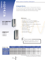
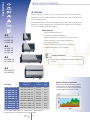
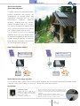
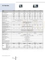
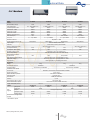
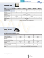
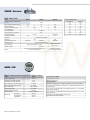
1
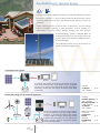
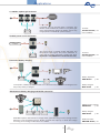
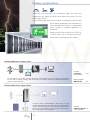
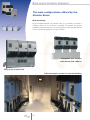
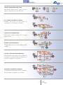
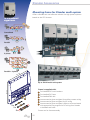
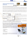
Battery chargers
Inverter-chargers
Battery monitoring
Engineered power
Inverters
Battery splitters
Battery separators
MPPT solar charge controllers
DC/DC converters
SWISS made power
Summary
The company
Applications
3
6
- Applications in remote areas
6
- Mobile applications
8
- Backup applications
10
- Self-consumption systems
12
Products
14
- MPPT solar charge controllers
14
- Sine wave inverter-chargers
18
- Sine wave inverters
28
- Battery chargers
30
- DC/DC converters
31
- Battery splitters
32
- Battery separators
32
- Battery protection
33
- Battery monitoring
33
Appendices
34
- Technical data
36
- How to find us
44
Photos credits
Robert Hofer, Céline Ribordy: Studer’s products; EB techniek/De Hoeve: p. 8; Hacksss-Fotolia.com: p. 10;
Getek AS: p. 24; Meteorisk: p. 3, 44; Perspective: p. 5, 30; SEI AG: p.12; Siblik: p. 29; Solarni Panely: p. 20;
Steca: p. 6 bottom; Studer Innotec SA: p. 15, 19.
Graphism
Atelier Perspective, R. Gigon, Sion.
January 2014
2
Company
Studer Innotec was established in 1987, not as a result of market
research, but founded on my wish to improve solar systems.
Therefore it was natural to focus on the main component of a
battery system: the inverter.
Three years later the company was manufacturing its first inverter
models, eight years later it started to export them and then
gradually opened up to new application areas (mobile applications,
backup systems and industrial applications).
Today Studer Innotec provides an extensive product range with
over 60 products that assure storage, conversion and management
of energy, of which over 95% are exported through our distributor
network with over 100 partners worldwide.
The key success factor in maintaining our competitive lead is constant
innovation. Through its know-how and experience, Studer Innotec
ensures the renewal of its product range as well as expanding into
new applications such as self-consumption systems and mini-grids.
Our company’s vision is the same as at its beginnings: more than
a product, we offer innovative solutions to optimise any solar
system whatever the application. These solutions are designed
and manufactured at the same location, in Sion, Switzerland, as a
result of the close collaboration and interaction with our customers.
Roland Studer
Founder and CEO of Studer Innotec SA
3
Production integration and flexibility
Studer Innotec’s company philosophy has always been to master
the complete process: from development to product sales. That
is why Studer Innotec since its beginning is a vertically integrated
company, capable of far greater flexibility than its competitors.
Furthermore it has a team of 13 Research & Development engineers
fully dedicated to turn the market expectations into products and
services.
The performance choice
In order to comply with Studer Innotec’s high-tech product concept
including outstanding performance and reliability, the company
choose its components with greatest care. This is the reason why
Studer Innotec has selected the latest technologies; such as digital
signal processors (DSP) that provide higher efficiency to its inverters.
Quality without compromise
Studer Innotec is an ISO enterprise that develops and manufactures
its products entirely in Switzerland. It also upholds its commitment
to an efficient and sustainable energy environment supplying to the
market high quality products.
4
Company
Ease in use and product versatility
Quality choice will continue to guide Studer Innotec’s strategic axis towards the
future. Beyond performance, the next inverters will have increased ease of use and
will offer greater versatility to the users.
Proximity with clients
From research to commercialisation, Studer Innotec endeavours to carry on its human
and financial investments in order to keep its lead in terms of global offer and proximity
with clients. This closeness is maintained by a network of distributors and qualified
service partners. Partner addresses can be found on the company website, under
« Distributors ».
In order to offer its partners an in-depth knowledge of its products and guarantee high
end support, Studer Innotec organizes twice a year trainings called Studer Qualidays.
Taking place over two to three days, depending on the modules chosen, Qualidays is
also a remarkable opportunity for participants to share experiences with each other.
The Qualidays are organised in the heart
of the Swiss Alps in Sion, at Studer
Innotec’s Headquarter and manufacturing
centre.
5
Applications in remote areas
Security and comfort (lighting, heating, household appliances, leisure
electronics, telecom...) can now be provided by autonomous energy
systems; when far away from any electrical grid, either by choice or
necessity.
These systems consist of three main components: first an energy
source; normally a genset, a solar generator, a wind turbine or a
combination of these; second battery storage; and third devices
(inverter/charger, battery charger) able to
charge the battery from the energy source(s)
and to supply users with AC voltage (inverter,
inverter/charger).
The examples below show the products in
some stand-alone applications.
A complete solar system
AC
DC
DC
A complete solar system can be built by combining an inverter
from the AJ series and the “ solar charge control “ integrated
function (as an option). One single device can then both supply
alternating current (AC) and charge the battery with direct
current (DC).
Inverters
AJ Series
(275 - 2’400VA)
p. 28
Quality AC voltage for all electrical appliances
DC
AC
DC
REGULATOR
DC
6
The inverter supplies, exclusively from a battery,
any kind of appliance using AC voltage, without
exception. It converts the battery’s DC voltage
into AC voltage at a higher quality than what is
available from the public grid. The MPPT solar
charge controller optimally charges the battery
from the solar generator.
Inverters
Xtender Series p. 18
(900 - 72’000VA)
Compact Series p. 26
(1’400 - 4’000VA)
AJ Series
p. 28
(275 - 2’400VA)
MPPT solar charge
controllers
VarioTrack
p. 14
Series
(65 - 80A)
VarioString
p. 15
(120A)
Applications
Village electrification
GENERATOR
REGULATOR
AC
GRID
INVERTER
GRID
INVERTER
DC
Inverters
Xtender Series p. 18
(900 - 72’000VA)
Various power sources supply energy to several consumer points.
Hybrid system: more autonomy and flexibility
Inverters
Xtender Series p. 18
(900 - 72’000VA)
Compact Series p. 26
(1’400 - 4’000VA)
GENERATOR
DC
AC
This hybrid system provides great flexibility in supply and
increased autonomy in relation to each energy source.
The appliances are supplied with AC voltage directly from
the energy source through the transfer relay, or from the
battery through the inverter function. The charger function
allows battery charging with the genset. The genset’s size
can be reduced thanks to the Smart-Boost function.
(Application note AN007/www.studer-innotec.com)
MPPT solar charge
controllers
VarioTrack
p. 14
Series
(65 - 80A)
VarioString
p. 16
(120A)
3-phase grid 3 x 400Vac for high power appliances
GENERATOR
AC
AC
DC
Inverters
Xtender Series p. 18
(900 - 72’000VA)
REGULATOR
DC
A 3 x 400Vac 3-phase grid can be
built with 3 inverters for supplying
high power appliances. In case of an
increased power requirement, it is
possible to connect up to 3 inverters in
parallel on each phase (Xtender only).
7
MPPT solar charge
controllers
VarioTrack
Series
p. 14
(65 - 80A)
VarioString
p. 16
(120A)
Mobile applications
A simple on-board energy system is often necessary to power the
AC voltage appliances, while the vehicle or the boat is away from
the electrical grid (port, garage, camping...).
In this case, energy is stored in the battery, which is actually charged
by power sources on-board, such as a genset, solar generator,
wind turbine, alternator or a combination of these. Studer Innotec
offers a complete product range that ensures the management and
conversion of this energy, while securing an optimal power supply
to the on-board appliances.
The examples below show our products in
some mobile applications.
A simple and reliable on-board system
AC
The inverter/charger charges the battery from the grid
or from a genset, and powers any kind of electrical
appliance. It converts the battery DC voltage to AC voltage.
Models equipped with the Smart-Boost system can add
the source’s power to that of the inverter.
DC
AC
Inverters
Xtender Series p. 18
(900 - 72’000VA)
Compact Series p. 26
(1’400 - 4’000VA)
An upgradeable power
AC
DC
AC
The amount of power available to the users can be
increased over time by adding inverters in parallel or by
creating additional phases. It is possible to install up to 9
inverters in a 3-phase power system.
8
Inverters
Xtender Series p. 18
(900 - 72’000VA)
Applications
3 x 400Vac 3-phase grid on-board
AC
DC
AC
A 3-phase grid can be built with 3 inverters. The
Xtender series enables the creation of a 3-phase grid
and to simultaneously charge the battery, even if only
a single phase is available as a power source.
Inverters
Xtender Series p. 18
(900 - 72’000VA)
Variable power source assistance
AC
AC
DC
VARIABLE POWER
SOURCE
The source being a variable power alternator, the
Smart-boost will supply the power difference in
order that the power delivered is always the same
(Application note AN004/www.studer-innotec.com).
Inverters
Xtender Series p. 18
(900 - 72’000VA)
Successive battery charging
AC
C
D
DC
AC
Battery separators
MBR Series
p. 32
MOTOR
DC
In this system, a battery separator enables one or several auxiliary batteries to be charged, once
the primary battery is charged.
Battery chargers
MBC series
p. 30
Simultaneous battery charging and DC/DC conversion
MOTOR
DC
DC
AC
MOSFET battery splitters
MBI Series
p. 32
DC
DC
Battery chargers
MBC Series
A MOSFET splitter, with almost no voltage losses, splits the charge current among several
batteries. From the battery pack, a DC/DC converter will step up or down the voltage
according to the voltage of the users: 12 or 24Vdc.
9
p. 30
DC/DC converters
MDCI-MDC Series p. 31
Backup applications
Appliances such as fridges, PCs, emergency lights, etc. which are
supplied by the public grid and cannot afford any power cut, are
electrically secured.
An inverter/charger with transfer relay or a combination of an inverter
and a charger guarantees that the battery is
well maintained and that an uninterrupted
power supply to strategic appliances is
sustained.
Studer Innotec offers solutions from 275VA up
to 72kVA with a one of a kind product choice
that remains unchallenged on the market.
Uninterruptible power supply on-line
AC
DC
AC
Inverters
AJ Series
(275 - 2’400VA)
In this system, the battery charge functions and appliances’ power supply are separated:
On one side is a battery charger, and on the other, an inverter. Grid current fluctuations have no
impact on the appliances.
Battery chargers
MBC Series
p. 28
p. 30
Uninterruptible power supply off-line
Compact series inverter/charger with built in solar
charger allows buildup of simple alone one solar backup
system with solar priority. The connected loads runs on
the sun as long as there is enough energy in the system.
Else it will rely on the utility grid.
10
Inverters
Compact Series p. 26
(1’400 - 4’000VA)
Applications
UPS with solar backup and solar priority
When it is forbidden or there is no incentive to inject
energy into the public grid, an Xtender invertercharger combined with VarioTrack or VarioString
MPPT solar charge controller will minimize the
grid consumption in favour of the locally produced
energy. They will also guarantee an energy supply
in case of grid-failure. This solution is easy to setup using Studer products.
Inverters
Xtender Series p. 18
(900 - 72’000VA)
Compact Series p. 26
(1’400 - 4’000VA)
Individual Home backup
AC
An inverter/charger is
used to provide backup
power in case of public
grid outage. As soon as
the power shuts down the
inverter/charger switches
to inverter mode and
assures an uninterruptible
power supply.
DC
AC
Inverters
Xtender Series p. 18
(900 - 72’000VA)
Compact Series p. 26
(1’400 - 4’000VA)
Solsafe – a backup system for grid connected solar installations
DC
GRID
INVERTER
Compteur
AC
DC
AC
Secured
Not secured
The installation of our Solsafe solution in a grid connected solar system provides the option to secure the power supply in case of a power cut to all loads or only priority loads,
and thus maintains the ongoing use of solar energy being produced.
(Application note AN003/www.studer-innotec.com).
11
Inverters
Xtender Series p. 18
(900 - 72’000VA)
Compact Series p. 26
(1’4000 - 4’000VA)
Self-consumption systems
In order to give priority to consumption of the energy generated from
your own solar or renewable installation, different systems including
the Xtender inverter-chargers can be set up.
These systems store excess energy produced during daytime in batteries to be used at a later time, maximizing self-consumption. The
public grid will only be used to import or export small amounts of
energy if absolutely necessary.
Simple solar priority system
Compact series inverter/charger with built-in (or external) solar charger allows to buildup a simple
solar backup system with solar priority. The connected loads run on the sun as long as there is
enough energy in the system. When the battery is below a certain level, it will rely on the utility grid.
12
Inverters
Compact Series p. 26
(1’400 - 4’000VA)
Applications
Priority to renewable energy without grid-injection
Inverters
Xtender Series p. 18
(900 - 72’000VA)
When it is forbidden or there is no incentive to inject energy into the public grid, an
Xtender inverter-charger combined with VarioTrack or VarioString MPPT solar charge
controller will minimize the grid consumption in favour of the locally produced energy.
They will also guarantee an energy supply in case of grid-failure. This solution is easy to
set-up using Studer products.
MPPT solar charge
controllers
p. 14
VarioTrack
Series
(65-80A)
VarioString
p. 15
(120A)
Optimising self-consumption with partial backup
This system has the advantage of being easily integrated into an existing grid-feeding
installation even when its power is higher than that of the Xtender. The self-consumption
is optimized by means of an expert control system (SCADA) supplied by partners of Studer
Innotec. This system also allows creating a separate secure grid adapted for selected
backup appliances (e.g. lights, cooling systems and communication).
Inverters
Xtender Series p. 18
(900 - 72’000VA)
Optimising self-consumption with full backup
This system will secure all user (household) appliances however it requires that the power
of the Xtender is at least equivalent to the grid inverter and that it covers the household’s
power needs. The self-consumption is optimized by means of an expert control system
(SCADA) supplied by partners of Studer Innotec. A correctly sized system adapted to meet
the customer’s needs guarantees the energy supply during power outages of the public grid.
13
Inverters
Xtender Series p. 18
(3500 - 72’000VA)
Applications
MPPT solar charge controller
VarioTrack Series
The VarioTrack solar charge controller maximizes the energy
generated from solar panels in any solar installation. It contains an
MPPT (Maximum Power Point Tracking) algorithm that continuously
tracks the maximum power point and automatically charges the
batteries in an optimal way with all the available solar power.
Main features
• Easy and safe commissioning with full protection
against incorrect wiring
• Rugged and durable, this device is designed to
VarioTrack
perform in harsh environmental conditions (IP54)
VT-65
• High conversion efficiency >99%
• Up to 15 VarioTrack in parallel on the same
communication bus
• 4 step charger for longer battery life
• Low self-consumption: <1W in night time mode
• Display with 7 LEDs showing status and current
• Comprehensive display, programming
and datalogging with RCC-02/-03
• Web access through Xcom-LAN or Xcom-GSM
• Suitable for any solar system
VarioTrack
• Optimal usage in an Xtender
system with synchronized
battery management
DC
VT-80
VarioTrack range
VT-65
VT-80
Nominal battery
voltage
Maximum power of
the solar generator
Maximum voltage of
the solar generator
12 V
1000 W
80 Vdc
24 V
2000 W
150 Vdc
48 V
4000 W
150 Vdc
12 V
1250 W
80 Vdc
24 V
2500 W
150 Vdc
48 V
5000 W
150 Vdc
Maximum charging
current to the battery
65A
80A
* Complete technical specifications on page 34
14
Products
The VarioTrack in an Xtender system
Designed to function in any solar installation, the VarioTrack works optimally in an Xtender system. The
communication between the two devices allows for synchronized battery management.
GENERATOR
DC
AC
Display and programming possibilities
The VarioTrack is fitted with several indicator lights and a control button for its basic operation. It is also
possible to do basic programming using the DIP switches situated inside the device.
By adding a remote control and programming center RCC-02/-03, the VarioTrack can use all functions
available in the remote control such as display, programming, data logging etc.
15
Applications
MPPT solar charge controller
VarioString
Dual MPPT solar charge controller 120A/48V.
The VarioString has two fully isolated MPPT inputs, up to 600V(Voc)
or up to 900V(Voc) with MPPT inputs in series.
Main features
• Reduces Balance of System costs (Eliminates expensive wiring
for parallel strings, saving wires, connectors, junction boxes,
fuses, space, time, etc)
• Safe, simple and trouble free connection with SUNCLIXTM (Phoenix
Contact “tool free”) PV connector
VarioString
VS-120
• Fully protected against incorrect wiring
• Simplified safety rules by full isolation between PV and battery and
between MPPT inputs
• Any grounding strategy applicable thanks to isolated MPPT inputs.
Grounding system fault detection.
• Fast, precise, best in class tracking algorithm bring MPPT efficiency
>99%
• World champion for efficiency in isolated converter with >98 %
conversion efficiency
• 7kW per unit and up to 15 units in parallel: 105kW
• 4 step charger fully programmable for longer battery life
• 9 LEDs to monitor status and current
• Optimal usage in an Xtender system with synchronized battery
management
• Web access through Xcom-LAN or Xcom-GSM
• Comprehensive display, programming and data logging features
with RCC-02/-03
VS-120
MPPT1
MPPT2
1 + 2 in parallel
1 + 2 in serie
Maximum Solar Power recommended
3500 W
3500 W
7000 W
7000 W
13 A
13 A
26 A
13 A
Maximum open circuit voltage
600 Vdc
600 Vdc
600 Vdc
900 Vdc
Minimum functional circuit voltage
200 Vdc
200 Vdc
200 Vdc
400 Vdc
250-500 Vdc
250-500 Vdc
250-500 Vdc
500-750 Vdc
60 A
60 A
120 A
120 A
VarioString
Maximum PV Current
Recommended MPPT voltage
Maximum output current
Battery voltage
48 V nom. (38-68 V)
* Complete technical specifications on page 35
16
Products
...Flexibility without compromise!
Two independent MPPT inputs each with 200 - 600Voc (2 x 3.5kWp)
Two MPPT inputs allow independent tracking of 2 different PV strings,
Voc, and/or power, which brings optimized efficiency and greater
flexibility for building integration.
Two MPPT inputs in parallel each with 200 - 600Voc (2 x 3.5kWp)
Parallel wiring allows simplified wiring with lower voltage when strings
are the same in size, power and orientation.
Two MPPT inputs in series with 400 - 900Voc (7kWp)
Serial wiring allows the greatest flexibility and simplest wiring with any
PV module on the market.
The VarioString in an Xtender system
Designed to function in any solar installation, the VarioString works optimally in an Xtender system. The
communication between the two devices allows for a synchronized battery management.
Display and programming possibilities
The VarioString is fitted with several indicator lights and a control button for its basic operation. It is also
possible to do basic programming using the DIP switches situated inside the device.
By adding a remote control and programming center RCC-02/-03, the VarioString can use all functions available
in the remote control such as display, programming, data logging, etc.
17
Applications
Sine wave inverter-chargers
Xtender Series
Xtender
XTS
XTS 900-12
XTS 1200-24
XTS 1400-48
The Xtender series provides unmatched freedom of use due to
its many functions. In a basic application, it offers a total package:
the functions of inverter, battery charger, transfer system and
assistance to the source. These functions can be combined and
controlled in a totally automatic way for exceptional ease and
optimal management of available energy.
The Xtender is equipped with a command entry and 2 configurable auxiliary
contacts. This allows automatic control of a genset or loadshedding when
the battery voltage is too low. The flexibility obtained makes it possible
to implement special functionalities, often necessary for good energy
management in standalone systems.
Main features
IP54
• Outstanding efficiency and overload
• Perfect management and limitation of AC sources
• Power shaving of the consumption peaks
• Automatic allocation of available power
• Active filtering of load steps on the genset
Xtender
XTM
• Automatic protection of the sources against overload
• Battery priority (or to renewable sources)
• Parallel and three-phase setting, up to 9 units (72kVA)
XTM 1500-12
XTM 2000-12
XTM 2400-24
XTM 2600-48
XTM 3500-24
XTM 4000-48
• Powerful multi-stage PFC charger
• Ultra-short transfer time (from 0 to 15ms max.)
• Automatic and efficient stand-by
• 2 programmable auxiliary contacts (optional on the XTS)
• Compatible with AC coupling
• XTS electronically protected against reverse polarity
• Display, programming and data logging integrated
in the remote control (RCC)
• Interactive with the Battery Status Processor (BSP)
Xtender
XTH
• RS-232 communication for remote supervision
XTH 3000-12
XTH 5000-24
XTH 6000-48
XTH 8000-48
GENERATOR
AC
18
GRID
INVERTER
DC
REGULATOR
DC
The Xtender series offers an optimal use of all
sources that can be found in hybrid systems,
whatever their connecting mode (AC or DC bus),
up to the nominal power of the Xtender system
(single, parallel and/or three phase).
DC
DC
Products
Output power
P30/Pnom
Power
Smart-Boost
Battery
voltage
AC
voltage
Charge
current
Transfer
current
900 VA** / 500 VA
900 VA**
12 V
230 Vac*
0 - 35 A
16 A
XTS 1200-24
1200 VA** / 650 VA
1200 VA**
24 V
230 Vac*
0 - 25 A
16 A
XTS 1400-48
1400 VA** / 750 VA
1400 VA**
48 V
230 Vac*
0 - 12 A
16 A
XTM 1500-12
1500 VA / 1500 VA
1500 VA
12 V
230 Vac*
0 - 70 A
50 A
XTM 2000-12
2000 VA / 2000 VA
2000 VA
12 V
230 Vac*
0 - 100 A
50 A
XTM 2400-24
2400 VA / 2000 VA
2400 VA
24 V
230 Vac*
0 - 55 A
50 A
XTM 2600-48
2600 VA / 2000 VA
2600 VA
48 V
230 Vac*
0 - 30 A
50 A
XTM 3500-24
3500 VA / 3000 VA
3500 VA
24 V
230 Vac*
0 - 90 A
50 A
XTM 4000-48
4000 VA / 3500 VA
4000 VA
48 V
230 Vac*
0 - 50 A
50 A
XTH 3000-12
3000 VA / 2500 VA
3000 VA
12 V
230 Vac*
0 - 160 A
50 A
XTH 5000-24
5000 VA / 4500 VA
5000 VA
24 V
230 Vac*
0 - 140 A
50 A
XTH 6000-48
6000 VA / 5000 VA
6000 VA
48 V
230 Vac*
0 - 100 A
50 A
XTH 8000-48
8000 VA / 7000 VA
8000 VA
48 V
230 Vac
0 - 120 A
50 A
Xtender range
XTS 900-12
* For the 120Vac/60Hz version, -01 is added to the model designation
** These features are valid only when using the cooling module ECF-01
Complete technical specifications on page 36
Smart-Boost function and active filtering
With this function it is possible to interact directly with the AC source (Genset or grid)
and to implement some basic functions such as:
• Efficient and immediate limitation of the current of the source, including
none linear or inductive/ capacitive loads, protecting efficiently the breakers
during connection to shore power or to a camping power meter with limited
current (function of power shaving and power assistance) (more information
on our website and in the Application note AN001/www.studer-innotec.com).
• Power shaving of load steps on the generator allowing an optimal
sizing of the generator and assuring the best possible efficiency of the fossil
fuels (function of filtering and of power assistance).
Generator
or Grid
Xtender
Charge
Battery
The function of assistance to the source enables also to implement advanced functions such as the priority
use of renewable energy, even when the grid is available (more information on our website and in the
Application note AN002/www.studer-innotec.com).
The new alpine cabin of Monte-Rosa
with an Xtender system
19
Sine wave inverter-chargers
The main configurations offered by the
Xtender Series
Wide modularity
By the implementation of several units, it is possible to create a
3-phase source or to set them in parallel to increase the power
available without extra cost. Up to 9 inverters of the Xtender Series
can be combined together for up to 72kVA!
Compatible with standard
cable channel (230 x 60mm)
Easy set up of multi-units
Self-consumption system for industrial building
20
Products
Inverter, charger and transfer relay
The Xtender works as an inverter and as a
charger, combined with a transfer relay.
GENERATOR
XT
XT
XT
GENERATOR
XT
XT
XT
XT
2 or 3 units in parallel on 1 phase
Increase the power on one phase by
connecting 2 or 3 Xtender in parallel.
GENERATOR
XT
XT
1 phase in and 3 phase out
Three-phase power supply from a single
phase source.
3 phase in and 3 phase out
Three-phase source for a three-phase power
supply.
XT
GENERATOR
XT
XT
GENERATOR
XT
XT
XT
3 phase + with one reinforced phase
Three-phase power supply with increase of
the power on one phase by connecting 2 or 3
Xtender in parallel on this phase.
XT
XT
GENERATOR
XT
XT
XT
XT
XT
XT
XT
XT
XT
XT
XT
GENERATOR
3 Xtender in parallel on 3 phases
Three-phase power supply with 3 Xtender
on each phase, for power up to 72kVA.
21
Xtender Accessories
Mounting frame for Xtender multi-system
Offers a flexible and cost effective solution for high power systems
based on the XTH inverter.
X-Connect
system
GENERATOR
XT
XT
XT
Centralized
GENERATOR
XT
XT
XT
Parallel
XT
XT
GENERATOR
XT
3-phase
XT
XT
XT
XT
XT
XT
XT
XT
XT
GENERATOR
Parallel + 3-phase
m
7m
91
Up to 72kVA multi-unit system
981 mm
Frame is supplied with:
2
1
3
4
3x
9x
5
6
1
Pre-installed DC circuit breakers
2
Pre-installed DC fuses
3
Pre-installed DIN rails
4
Interconnection pipes and gland for auxiliary contact wiring
5
Interconnection pipes and gland for AC wiring
6
Interconnection pipes and gland + 90mm2 wire terminated
with appropriate ring tongues for DC wiring from Xtender
to breakers and fuses
Screws set for frame assembly
3x
22
Products
Xtender/VarioTrack/VarioString
Accessories
RCC-02
RCC-03
Remote control and programming centre RCC-02 or RCC-03
Apart from the enclosure difference, adapted for wall or panel mounting, both units have exactly the same
features and allow the user to survey his system and fully customize it to his needs. The RCC gives a controlled
access to the many adjustable parameters of the Xtender and the VarioTrack/VarioString. It enables the setting
of the charge curve of the battery, the programming of the auxiliary contacts and gives access to a lot of
operation options. Thanks to its graphic display the RCC provides clear and comprehensive indications on the
state of the system in a selectable language. The unit records and displays the events that occurred on an
installation and so it anticipates the problems that might appear. A slot for an SD card is incorporated in the
RCC which allows parameters and log data to be recorded as well as a software update of the entire system.
Data logging and analysis
Analyse easily your data with the RCC-02/-03 Data
logger function that will record on the SD card the
main electrical values of your Xtender system during
its operation.
These standards enable the analysis of the system’s
energy consumption evolution, to check the power
cuts, the state of the auxiliary contacts, the input
currents and voltages, etc.
Studer Innotec offers for free a graphical and analysis tools, Xtender Data Analysis Tool. (more information
on our website and in the Application note AN006/www.studer-innotec.com).
Battery Status Processor BSP for XTENDER and VarioTrack/VarioString systems
One of the most important values for safe and effective operating of an
energy system with batteries is their state of charge.
The BSP offers, for Xtender and VarioTrack/VarioString systems, a highly
precise measuring and an extremely efficient algorithm that calculates
the state of charge in the most accurate way.
The remote control RCC-02/-03 provides data logging, the display of
values and the graphical display of the state of charge history and the
settings. Values of the BSP can be used in the programming of Xtender
and VarioTrack/VarioString systems. In addition, 17 different values can
be displayed such as:
•
•
•
•
•
•
State of charge
Voltage (12-24-48Vdc)
Current
Time to go
Throughput energy
Battery temperature
The two models, BSP 500 and BSP 1200, are supplied with a 500A or
1200A shunt respectively, a 5m cable for battery connection, and a 5m
communication cable.
23
Communication for Xtender/
VarioTrack/VarioString
Internet based communication sets Xcom-LAN, Xcom-GSM
Xtender and/or VarioTrack/VarioString systems can be constantly
controlled from any remote
terminal, computer, tablet or
smartphone. The communication
sets Xcom-GSM and Xcom-LAN
allow connecting to sites with
GSM mobile coverage or with
internet-connection over a local
network.
Studer Innotec provides this «plugand-play» solution using a secure
server and a simple and userfriendly interface. The interface
allows for remote interaction with
the installation exactly as if on-site with the remote control RCC-02/-03, including: access to all parameters,
real-time display of measured data and 30 days datalog of all devices included in the system.
Furthermore this solution makes it possible to configure the alarm trigger, sending alarm messages to one or
several persons by e-mail or by SMS, and to view the event log at any time to consult the messages sent by
the system.
Xcom-GSM or Xcom-LAN?
The available means of communication at the location of the installation will determine which set to choose.
If the installation has access to internet through a local area network (LAN), choose the Xcom-LAN set. If
there is no available connection to the internet but access to a GPRS or 3G mobile network, choose the
Xcom-GSM set.
Xtenders in the heart of the Spitzbergen...
24
Products
Xtender/VarioTrack/VarioString Accessories
XTS XTM XTH VT
VS
RCC-02/-03
The remote control module (with 2m cable) enables the setting of the
parameters as well as the display of the values measured. By means of an
SD card it is possible to log the system data and to save and restore the
parameters of the system. This module is available either for wall mounting
(model RCC-02), or for panel mounting (model RCC-03).
l
l
l
l
l
BTS-01
Battery temperature sensor (with 5m cable) offering the automatic compensation of the adjustable thresholds of the battery voltage.
l
l
l
l
l
RCM-10
Module for rail DIN mounting (with 5m cable) giving access to the main ON/OFF
and to the command entry with the models XTS and XTM.
l
l
BSP 500/1200
Module meant for the measuring and calculating of the battery state of charge (with
5m cable). This module is connected to the communication bus of the Xtender.
It allows the display and the datalogging of the values measured and calculated (see
opposite screens) and also the control of the 2 auxiliary contacts of the Xtender.
l
l
l
l
l
Xcom-232i
Communication module with RS-232 port and 2m RJ45 cable, allowing
access to the parameters and measured values of the Xtender system.
It makes the link between an Xtender system and a SCADA supervision or
control system (not supplied).
l
l
l
l
l
l
l
l
l
l
l
l
l
l
l
l
Xcom-GSM
Internet based communication sets.
The Xcom-GSM set includes one Xcom-232i, one cellular modem and all
necessary accessories. The SIM card is not provided.
Xcom-LAN
Internet based communication sets.
The Xcom-LAN set includes one Xcom-232i, one Ethernet bridge and all
necessary accessories.
ARM-02
This module, only meant for the XTS and for the VT/VS models and for rail
DIN mounting, is equipped with 2 auxiliary contacts controlled by the XTS
or by the VT/VS.
This function is already integrated in the models XTM and XTH.
l
l
ECF-01
External cooling module (IP54) for XTS and VarioTrack (VT-65 only).
The use of this accessory will increase the power of the XTS and the current
of the VT65 to 80 A. The ECF-01 is directly installed on top of the casing and
its mounting can be done at any time after installation.
l
l
X-Connect
Mounting frame for multi-XTH system, supplied as a kit. The frame is equipped
with DC breakers and fuses, and with rail DIN for the mounting of protection
devices upstream and downstream (see p. 22).
CAB-RJ45-8-xx
Communication cable for the connection between Xtenders and to all external
accessories. The cables are available in the following lengths: 2, 5, 10, 20
or 50m (xx stands for the length). For instance: one system with 3 Xtenders
requires 2 cables of 2m. One cable is supplied with every accessory. However
a longer cable can be ordered when necessary.
25
l
l
l
l
l
l
Applications
Sine wave inverter-chargers
Compact Series
The Compact series models consist of 3 fully automatic functions: a
sine wave inverter, a battery charger and a transfer system. Equipped
with high-end technology, they optimally perform, thanks to Studer
Innotec’s extensive experience in the field of electrical supply.
Main features
• True sine wave voltage
• Suitable for any kind of electrical appliance
XP COMPACT
• Reliable and silent working with all kind of loads
XPC 1400-12
XPC 2200-24
XPC 2200-48
• Outstanding overload capabilities
• Stand-by level adjustable over a large range and from
a very low threshold
• 4 STEP battery charger with PFC
• Ultra-fast transfer relay
• High efficiency
• Full internal protection
• Ultra-fast regulation
COMPACT
• Microprocessor controlled
C 1600-12
C 2600-24
C 4000-48
E
24
Norm E certification
The XPC 1400-12, XPC 2200-24, C 1600-12 and
C 2600-24 are certified to the ECE-R 10 norm.
Output power
P30/Pnom
Battery
voltage
AC
voltage
Charge current
Transfer
current
Solar
option (-S)
XPC 1400-12
1400 VA / 1100 VA
12 Vdc
230 Vac*
0 - 45 A
16 A
30 A
XPC 220O-24
2200 VA / 1600 VA
24 Vdc
230 Vac*
0 - 37 A
16 A
30 A
XPC 2200-48
2200 VA / 1600 VA
48 Vdc
230 Vac*
0 - 20 A
16 A
20 A
C 1600-12
1600 VA / 1300 VA
12 Vdc
230 Vac
0 - 55 A
16 A
30 A
C 2600-24
2600 VA / 2300 VA
24 Vdc
230 Vac
0 - 55 A
16 A
30 A
C 4000-48
4000 VA / 3500 VA
48 Vdc
230 Vac
0 - 50 A
16 A
20 A
Compact range
* For the 120Vac/60Hz version, -01 is added to the model designation
Complete technical specifications on page 37
26
Products
Optional built-in solar charge controller (-S)
Simple and robust hybrid system
Compact or XP-Compact series inverter/
charger with built in PWM solar charger
allows for a simple stand-alone solar/
diesel hybrid system. Compact, efficient,
robust and delivered with battery cables.
It is it a cost effective choice for small
solar hybrid systems.
12V/24V model => solar charge controller: 30A
48V model => solar charge controller: 20A
Multifunction programmable auxiliary relay
The 16A potential free contact can be programmed according to the user wishes. It reacts according to battery
levels, as well as to the system status (alarm conditions, presence of public grid or sunlight...), and can be
used for many diverse applications
such as:
Load shedding according to
battery status
Alarm signalization or start of
genset according to battery status
or power output
Conditional connection to
AC source to increase self
consumption of renewable
energy
Accessories
XP COMPACT
COMPACT
RCC-01
The remote control provides state of the system displayed by LED and
remote programming* (supplied with a 20m cable).
*compulsory for the programming of the XP Compacts
l
l
CT-35
This temperature sensor adapts charge levels to the battery’s temperature
variations (supplied with 3m cable).
l
l
ARM-01
The Auxiliary relay module equipped with 3 programmed relays and a
fourth one which is like the inverter-charger’s auxiliary contact. This
module allows the Solsafe system to be implemented (see page 11).
l
l
CFC-01
This cover provides additional connection protection by means of glands.
l
l
C-IP22
Cover for a protection against intrusions or projections, installed after the
mounting of the device. It extends the protection index of the XP Compacts
and Compacts from IP 20 to IP 22.
l
l
27
Applications
Sine wave inverters
AJ Series
The AJ range consists of sine wave inverter that convert battery
voltage into utility quality 230Vac* which can be used with all usual
electrical appliances.
Its proven reliability and outstanding performance make it the optimal
solution for many applications. Delivered with battery and AC cables
it is a true «plug and forget solution».
Main features
• High and steady efficiency
• Outstanding overload capabilities
AJ
• Digital regulation and control by microprocessor
AJ 275-12
AJ 350-24
AJ 400-48
• Electrical supply to any type of appliance
• Full internal protection
• Battery lifetime optimization (B.L.O.) function
AJ
• Supplied with battery and AC cables
AJ 500-12
AJ 600-24
AJ 700-48
E
24
AJ
AJ 1000-12
AJ 1300-24
Norm E certification
The AJs in 12 and 24Vdc are certified to the ECE-R
10 norm.
AJ
AJ 2100-12
AJ 2400-24
Output power
P30/Pnom
Battery
voltage
Solar
option
(-S)
AJ 275-12 (-S)
275 VA / 200 VA
12 Vdc
10 A
AJ 350-24 (-S)
350 VA / 300 VA
24 Vdc
10 A
AJ 400-48 (-S)
400 VA / 300 VA
48 Vdc
10 A
AJ 500-12 (-S)
500 VA / 400 VA
12 Vdc
15 A
AJ 600-24 (-S)
600 VA / 500 VA
24 Vdc
15 A
AJ 700-48 (-S)
700 VA / 500 VA
48 Vdc
15 A
AJ 1000-12 (-S)
1000 VA / 800 VA
12 Vdc
25 A
AJ 1300-24 (-S)
1300 VA / 1000 VA
24 Vdc
25 A
AJ 2100-12 (-S)
2100 VA / 2000 VA
12 Vdc
30 A
AJ 2400-24 (-S)
2400 VA / 2000 VA
24 Vdc
30 A
AJ range
For the 120Vac/60HZ version, -01 is added to the model designation
Complete technical specifications on pages 38-39
28
Battery Lifetime Optimizer:
With this activable function B.L.O. the AJ
inverters offer an advanced protection
of the battery, by a smart management
of low voltage disconnection (LVD)
Products
Rural electrification
(Solar Home System)
AJ series inverters for rural electrification
provide excellence that benefit the
development of remote areas and
populations. Choosing AC for rural
electrification
systems
improves
simplicity, reliability and cost savings.
Indeed, compared with a DC system,
one with an inverter that supplies loads
in AC, is often more efficient for systems
with 100W of solar power or more.
The AJ series is, due to its overload
capability and to its very reliable standby system adjustable from 2W, the most
suitable range of inverters to meet the
technical and economic requirements
of rural electrification projects.
Solar Home System with AJ
AJ with external
solar charge controller
AJ with built in solar
charge controller (-S)
Option built-in solar charge controller
For a complete solar system! The AJ series can be supplied with an optional integrated PWM solar charge
controller, making the inverter an “all in one” device for a solar home system.
Accessories
JT8 Remote control:
(supplied with a 5m cable) For AJ
1000-12 and bigger model. Enables
the control (ON/OFF) and the status
display of the inverter:
On, Standby, temporary Off
NOTE: For all other units from AJ275 to AJ700 its special
version with remote control feature is available through
a 3,2mm connector jack with 2 poles with the following
3 options:
RCM-01: inverter ON when contact is closed
RCM-02: inverter ON when voltage is across contacts
RCM-03: inverter is ON when contact is open
29
Applications
Battery chargers
MBC Series
The MBC chargers enable battery charging from an AC voltage
supply source (genset, public grid, shorepower, etc.). These chargers
are also watertight and therefore specially designed for outdoor
applications (IP 65).
Main features
• Universal input voltage
• Charge of lead acid batteries with liquid or gelled
(GEL) electrolyte
• Protection against battery overcharge
AC
DC
GENERATOR
MBC range
Battery voltage
Input voltage
Output current
Output
MBC 12-06/1
12 Vdc
230 Vac ±15%
6A
1
MBC 12-15/1
12 Vdc
230 Vac ±15%
15 A
1
MBC 24-03/1
24 Vdc
230 Vac ±15%
3A
1
MBC 24-08/1
24 Vdc
230 Vac ±15%
8A
1
MBC 24-15/1
24 Vdc
230 Vac ±15%
15 A
1
MBC 24-32/1
24 Vdc
230 Vac ±15%
32 A
1
Complete technical specifications on page 40
30
Applications
DC/DC converters
Products
MDCI and MDC Series
The DC/DC converters type MDCI and MDC are used, depending on the
model, either to step up or to step down a DC voltage.
The MDCI range converters are electrically isolated.
Main features
• High efficiency
• Low consumption
• Protection against short-circuit, overheating
overvoltage and reverse polarity
• Great stability of the output voltage for a more
reliable system
DC
DC
MDCI range
Power
Input variant
Output variant
Output Current
Isolated
MDCI 100
100 W
A/B/C/D
12.5/24 Vdc
8/4 A
Yes
MDCI 200
200 W
A/B/C/D
12.5/24 Vdc
16.5/8 A
Yes
MDCI 360
360 W
A/B/C/D
12.5/24 Vdc
30/15 A
Yes
MDCI 360 A24
Charger
330 W
A
24 Vdc
15 A
Yes
A = 9-18Vdc
B = 20-35Vdc
C = 30-60Vdc
D = 60-120Vdc
(ex. MDCI 200 D24)
Power
Input voltage
Output voltage
Output Current
Isolated
MDC 1224-7
170 W
9-18 Vdc
24 Vdc
7A
No
MDC 2412-5
65 W
18-35 Vdc
13.2 Vdc
5A
No
MDC 2412-8
105 W
18-35 Vdc
13.2 Vdc
8A
No
MDC 2412-12
160 W
20-35 Vdc
13.2 Vdc
12 A
No
MDC 2412-20
275 W
20-35 Vdc
13.8 Vdc
20 A
No
MDC 2412-30
415 W
20-35 Vdc
13.8 Vdc
30 A
No
MDC range
Complete technical specifications on page 40
The MDC 2412-20 and 2412-30, as well as the MDCI 360 A24 “Charger” can also be used to charge a battery.
31
Applications
MOSFET battery splitters
MBI Series
The MBI MOSFET battery splitters supply current from the charger or
alternator to several batteries. They generate an insignificant voltage
drop. All batteries are thus charged at the same time, and therefore
will not charge or discharge each other.
Input
Charge
current
Charge
input
Outputs
MBI 100/2
12/24 Vdc
100 A
1
2
MBI 150/2
12/24 Vdc
150 A
1
2
MBI 100/3
12/24 Vdc
100 A
1
3
MBI 150/3
12/24 Vdc
150 A
1
3
MBI 200/3
12/24 Vdc
200 A
1
3
MBI 2-100/3
12/24 Vdc
100 A
2
3
MBI range
Complete technical specifications on page 41
Main features
• Automatic adjustment to the batteries voltage
• Possible charge of the battery from an alternator
AC
DC
• Voltage drop < 0.4V at 100 Amp
• Suitable for electronic alternators
MOTOR
DC
DC
Applications
Battery separators
MBR Series
The MBR battery separators allow to supply the auxiliary battery or the
appliances, as soon as the main battery voltage is high enough.
Battery
voltage
Charge
current
Batteries
MBR 12/24-100
12/24 Vdc
100 A
2
MBR 12/24-160
12/24 Vdc
160 A
2
MBR 12/24-500
12/24 Vdc
500 A
2
MBR range
Complete technical specifications on page 41
MOTOR
Main features
• Insignificant voltage drop
DC
• Protects the auxiliary battery from any
overvoltage
DC
DC
AC
32
DC
Products
Applications
Battery protection
MBW Series
The Battery Watch protects the battery from an excessive discharge and
also the consumers in case of overvoltage.
Main features and performances
• Programmed Connection and disconnection voltages
by jumpers
• MOSFET switches, therefore no sparks
• Alarm output to indicate excessive voltage drops
Operating voltage
range (Vdc)
MBW 40
40 A
6-35 Vdc
MBW 60
60 A
6-35 Vdc
200 A
8-32 Vdc
MBW 200
DC
DC
DC
Maximum
current
MBW range
Complete technical specifications on page 42
Battery monitoring
Applications
SBM-02
The SBM-02 is a highly accurate battery monitor with a data history
memory. It is supplied together with a 500A/50mV shunt. This device is
designed for 12 and 24V batteries. The optional SBM-PS-02 voltage prescaler extends the use of the SBM-01 to 27-175V batteries.
Main features and performances
• Digital display of the 6 most important
parameters of a DC power system:
1. Battery voltage (V)
2. Current (A)
DC
DC
3. Consumed Ampere-hours (Ah)
4. Sate-of-charge (%)
5. Time-to-go (h:m)
AUX
6. Temperature (°C or °F)
Optional accessories
• Connection kit, type SBM-CAB-20, including 20m of twisted pair cable (3 x 2 x 0.5mm2) and
2 fuseholders
• Communication kit, type SBM-COM, including RS232 interface box, 1.8m of 9p DSUB serial cable
and software
• Communication kit, type SBM-COM-USB, including USB interface box, 1.8m of USB cable and software.
• Temperature kit, type SBM-TEMP-20, with a temperature sensor and 20 m cable
• Shunt 1200A / 50mV, type SH-1200-50, for battery monitoring in large system
33
VarioTrack
Series
Model
Electrical characteristics PV array side
At nominal battery voltage
Maximum solar power recommended (@STC)
Maximum solar open circuit voltage
Maximum solar functional circuit voltage
Minimum solar functional circuit voltage
Electrical characteristics battery side
Maximum output current
Nominal battery voltages
Operating voltage range
Performances of the device
Power conversion efficiency (in a 48 V typical-system)
Maximum stand-by self-consumption (48 V)
Maximum stand-by self-consumption (24 V)
Maximum stand-by self-consumption (12 V)
Charging stages
Battery temperature compensation (available with accessory BTS-01)
Electronic protections
PV reverse polarity
Battery reverse polarity
Battery overvoltage
Over temperature
Reverse current at night
Environment
Operating ambiant temperature range
Humidity
Ingress protection of enclosures
Mounting location
General data
Warranty
Weight
Dimensions h/w/l [mm]
Parallel operation (separated PV arrays)
Max wire size
Glands
Communication
Network cabling
Remote control and display
Menu languages
Data logging
Accordance to standards
CE compliant
Safety
EMC (Electro Magnetic Compatibility)
Accessories
Remote control RCC-02 or RCC-03
Module Xcom-232i
Internet based communication sets Xcom-LAN, Xcom-GSM
Battery Status Processor BSP
2 aux. contacts module ARM-02
Cooling Module ECF-01
Battery temp. sensor BTS-01 (3 m)
Communication cable CAB-RJ45-8-2
Data may change without any notice
34
VT-65
12 V
1000 W
80 Vdc
75 Vdc
VT-80
24 V
48 V
12 V
2000 W
4000 W
1250 W
150 Vdc
80 Vdc
145 Vdc
75 Vdc
Above battery voltage
24 V
48 V
2500 W
5000 W
150 Vdc
145 Vdc
65 A
80 A
Automatic / manual set to 12, 24 or 48 Vdc
Above battery voltage, minimum 7 V
>99 %
25 mA > 1.2 W
30 mA > 0.8 W
35 mA > 0.5 W
4 stages: Bulk, Absorption, Float, Equalization
–3 mV /°C /cell (25°C ref) default value adjustable -8 to 0 mV /°C
Up to –150 Vdc
Up to –150 Vdc
Up to 150 Vdc
Protected
Prevented by relays
–20 to 55°C
100 %
IP54, IEC/EN 60529:2001
indoor
5 years
5.2 kg
120 / 220 / 310
5.5 kg
120 / 220 / 350
Up to 15 devices
35 mm2
M 20 × 1,5
STUDER communication BUS
RCC-02/-03 / Xcom-232i
English / French / German / Spanish
With RCC-02/03 on SD card · One point every minute
EMC 2004/108/CE · LV 2006/95/CE · RoHS 2002/95/CE
IEC/EN 62109–1:2010
IEC/EN 61000–6–3:2011 · IEC/EN 61000–6–1:2005
l
l
l
l
l
l
l
l
l
l
l
Included
l
l
l
l
Techical Data
VarioString
Model
Electrical characteristics PV array side
Maximum solar power recommended (@STC)
Maximum current
Maximum solar open circuit voltage
Minimum solar functional circuit voltage
Recommended MPPT voltage
Electrical characteristics battery side
Maximum output current
Nominal battery voltages
Operating voltage range
Battery grounding possibility
Performances of the device
Maximum efficiency
MPPT efficiency
Maximum stand-by self-consumption (48 V)
Charging stages
Battery temperature compensation (available with accessory BTS-01)
VS-120
MPPT 1
3500 W
13 A
600 Vdc
200 Vdc
250-500 Vdc
MPPT 2
3500 W
13 A
600 Vdc
200 Vdc
250-500 Vdc
1 + 2 in parallel
7000 W
26 A
600 Vdc
200 Vdc
250-500 Vdc
1 + 2 in series
7000 W
13 A
900 Vdc
400 Vdc
500-750 Vdc
120A (60A per MPPT)
48 Vdc
38 - 68V
Battery + or battery >98 %
>99 %
25 mA > 1.25 W
4 stages: Bulk, Absorption, Float, Equalization
–3 mV /°C /cell (25°C ref) default value adjustable -8 to 0 mV /°C
Electronic protections
PV reverse polarity
Battery overvoltage
Over temperature
Reverse current at night
Galvanic isolation
PV grounding possibility
Ground fault Protection
Environment
Operating ambient temperature range
Humidity
Ingress protection of enclosures
Mounting location
General data
Warranty
Weight
Dimensions h/w/l [mm]
Solar generation connection (6mm2)
Parallel operation (separated PV arrays)
Max wire size (batery)
Glands (batery)
Communication
Network cabling
Remote control and display
Menu languages
Data logging
Accordance to standards
CE compliant
Safety
EMC (Electro Magnetic Compatibility)
Accessories
Remote control RCC-02 or RCC-03
Module Xcom-232i
Internet based communication sets Xcom-LAN, Xcom-GSM
Battery Status Processor BSP
2 aux. contacts module ARM-02
Battery temp. sensor BTS-01 (3 m)
Communication cable CAB-RJ45-8-2
l
Up to max 80 Vdc
l
l
l
PV + , PV - , floating
Programmable
–20 to 55°C
maximum 95%, non-condensing
IP20
indoor
5 years
7.5kg
133 / 322 / 466
SUNCLIXTM (Phoenix Contact Tool Free)
2 pairs supplied with unit
Up to 15 devices
70 mm2
2xPG21
STUDER communication BUS
RCC-02/03 / Xcom-232i / Xcom-LAN / Xcom-GSM
English / French / German / Spanish
With RCC-02/-03 on SD card · One point every minute
EMC 2004/108/CE · LV 2006/95/CE · RoHS 2002/95/CE
IEC/EN 62109–1:2010
IEC/EN 61000–6–3:2011 · IEC/EN 61000–6–1:2005
l
l
l
l
l
l
l
Data may change without any notice
35
Xtender
Series
Model
Inverter
Nominal battery voltage
Input voltage range
Continuous power @ 25°C
Power 30 min. @ 25°C
Power 5 sec. @ 25°C
Maximum load
Maximum asymmetric load
* Load detection (stand-by)
Cos j
Maximum efficiency
Consumption OFF/Stand-by/ON
* Output voltage
XTS 900-12
XTS 1200-24
XTS 1400-48
XTM 1500-12
XTM 2000-12
XTM 3500-24
XTM 4000-48
XTH 3000-12
12Vdc
24Vdc
48Vdc
12Vdc
24Vdc
48Vdc
24Vdc
48Vdc
12Vdc
19 - 34Vdc
38 - 68Vdc
9.5 - 17Vdc
19 - 34Vdc
38 - 68Vdc
19 - 34Vdc
38 - 68Vdc
9.5 - 17Vdc
650**/500VA 800**/650VA 900**/750VA
1500VA
3000VA
3500VA
2500VA
900**/700VA
1200**/1000VA
1400**/1200VA
1500VA
2000VA
2000VA
2400VA
2600VA
3500VA
4000VA
3000VA
2.3kVA
2.5kVA
2.8kVA
3.4kVA
4.8kVA
6kVA
6.5kVA
9kVA
10.5kVA
7.5kVA
96%
93%
Up to short-circuit
Up to Pcont.
2 to 25 W
0.1-1
93%
93%
93%
1.1W/1.4W/7W
1.2W/1.5W/8W
1.3W/1.6W/8W
93%
94%
96%
1.2W/1.4W/8W 1.2W/1.4W/10W 1.4W/1.6W/9W
94%
1.8W/2W/10W
1.4W/1.6W/12W 1.8W/2.1W/14W 1.2W/1.4W/14W
Pure sine wave 230Vac (± 2%) / 120Vac (1)
Adjustable 45 - 60Hz (1) ± 0.05% (crystal controlled)
Harmonic distortion
Overload and short-circuit protection
Overheat protection
Battery charger
<2%
Automatic disconnection with 3 time restart attempt
Warning before shut-off - with automatic restart
6 steps: Bulk, Absorption, Floating, Equalization, reduced floating, periodic absorption
Number of steps, thresholds, end current and times completely adjustable with the RCC-02/-03
* Charge Characteristic
35A
XTS 900-12
25A
12A
70A
100A
55A
30A
90A
50A
160A
With BTS-01 or BSP 500/1200
EN 61000-3-2
XTS 1200-24 XTS 1400-48 XTM 1500-12 XTM 2000-12 XTM 2400-24 XTM 2600-48 XTM 3500-24 XTM 4000-48 XTH 3000-12
150 to 265Vac / 50 to 140Vac (1)
45 to 65Hz
16Aac/20Aac
50Aac/56Aac
<15 ms
Module ARM-02 with 2 contacts, in option
8.2 kg
9 kg
9.3 kg
110x210x310
110x210x310
110x210x310
IP54
Conformity
Operating temperature range
Relative humidity in operation
Ventilation
Acoustic level
Warranty
Accessories
Remote control RCC-02 or RCC-03
Module Xcom-232i
Internet based communication sets
Xcom-LAN, Xcom-GSM
Battery Status Processor BSP
Remote Control Module RCM-10 (3 m)
2 aux. contacts module ARM-02
Cooling Module ECF-01
Battery temp. sensor BTS-01 (3 m)
Communication cable for 3ph and // CAB-RJ45-8-2
Mounting frame X-Connect
XTM 2600-48
9.5 - 17Vdc
* Output frequency
* Maximum charging current
* Temperature compensation
Power Factor Correction (PFC)
General data
* Input voltage range
Input frequency
Input current max. (transfer relay) /
Output current max.
Transfer time
Multifunction contacts
Weight
Dimension hxwxl [mm]
Protection index
XTM 2400-24
100%
Optional cooling module ECF-01
2 independent contacts (potential free 3 points, 16Aac/5Adc)
15 kg
18.5 kg
16.2 kg
21.2 kg
133x322x466
22.9 kg
133x322x466
34 kg
230x300x500
IP20
Directive EMC 2004/108/EC: EN 61000-6-1, EN 61000-6-3, EN 55014, EN 55022, EN 61000-3-2, 62040-2
Low voltage directive 2006/95/EC: EN 62040-1-1, EN 50091-2, EN 60950-1
-20 to 55°C
95% without condensation
Forced from 55°C
<40dB / <45dB (without/with ventilation)
5 years
l
l
l
l
l
l
l
l
l
l
l
l
l
l
l
l
l
l
l
l
l
l
l
l
l
l
l
l
l
l
l
l
l
l
l
l
l
l
l
l
l
l
l
l
l
l
l
l
l
l
l
l
l
l
l
l
l
l
l
l
l
l
l
l
l
l
l
l
l
l
l
l
l
l
l
l
* Adjustable with the RCC-02/-03
** These features are valid only when using the cooling module ECF-01.
(1)
With -01 at the end of the reference, means 120V/60Hz. Available for all Xtenders except XTH 8000-48
Data may change without any notice
36
Techical Data
COMPACT
Series
XTH 5000-24
XTH 6000-48
XTH 8000-48
24Vdc
48Vdc
19 - 34Vdc
38 - 68Vdc
4500VA
5000VA
7000VA
5000VA
6000VA
8000VA
12kVA
15kVA
21kVA
94%
96%
1.4W/1.8W/18W 1.8W/2.2W/22W 1.8W/2.4W/30W
140A
100A
120A
XTH 5000-24 XTH 6000-48 XTH 8000-48
50Aac/80Aac
40 kg
42 kg
230x300x500
46 kg
230x300x500
l
l
l
l
l
l
l
l
l
l
l
l
l
l
l
l
l
l
l
l
l
Model
Inverter
Nominal battery voltage
Input voltage range
Continuous power @ 25°C
Power 30 min. @ 25°C
Power 5 sec. @ 25°C
Maximum power
Maximum asymmetric load
Stand-by adjustment
XPC 1400-12 XPC 2200-24 XPC 2200-48
12Vdc
9.5 – 16Vdc
1100VA
1400VA
24Vdc
19 - 32Vdc
1600VA
2200VA
C 1600-12
C 2600-24
C 4000-48
48Vdc
12Vdc
24Vdc
48Vdc
38 - 64Vdc 9.5 - 16Vdc 19 - 32Vdc 38 - 64Vdc
1600VA
1300VA
2300VA
3500VA
2200VA
1600VA
2600VA
4000VA
3 x Pnom
Up to short-circuit
Up to Pcont.
1 to 25W
0.1 - 1
Cos j
Maximum efficiency
94%
95%
94%
95%
Consumption OFF/Stand-by/ON
0.5/0.6/4W
0.8/0.9/7W
1.2/1.3/7W 0.5/0.6/6W 0.8/0.9/9W 1.2/1.4/12W
Output voltage
Sine wave 230Vac (±5%) (XPC also available in 120Vac)
Output frequency
50Hz ± 0.05% (crystal controlled)
Total harmonic distortion
< 4%
< 2%
Overload and short-circuit protection
Automatic disconnection with 3 time restart attempt
Overheat protection
Acoustic warning before shut-off - with automatic restart
Battery charger (4 STEP) I-U-Uo-Equalize (every 25 cycles)
Charging current adjustable
0 - 45Adc
0 - 37Adc
0 - 20Adc
0 - 55Adc
0 - 50Adc
Input current balance adjustment
Not available
1 - 16A
Maximum input voltage
265Vac
Input AC voltage range
Adjustable threshold from 150 to 230Vac (XPC also available in 120Vac)
Input frequency
45 - 65Hz
Power Factor Correction (PFC)
EN 61000-3-2
Battery control (thresholds and times adjustable by the user)
Absorption time
0-4 h
End charge cycle voltage*
14.4Vdc
28.8Vdc
57.6Vdc
14.4Vdc
28.8Vdc
57.6Vdc
Floating voltage*
13.6Vdc
27.2Vdc
54.4Vdc
13.6Vdc
27.2Vdc
54.4Vdc
Equalization time*
0-4 h
Equalization voltage*
15.6Vdc
31.2Vdc
62.4Vdc
15.6Vdc
31.2Vdc
62.4Vdc
Deep-discharge protection*
10.8Vdc
21.6Vdc
43.2Vdc
10.8Vdc
21.6Vdc
43.2Vdc
Temparature compensation
-3mV / ° C / Cell
(optional CT-35)
General data
Multifunction contact programmable
16A - 250Vac (potential free 3 points)
Max. current on transfer relay
16Aac
Transfer time
< 40 ms
Weight
11.7 kg
12.6 kg
16 kg
17.1 kg
29.4 kg
Dimension hxwxl [mm]
124x215x410
124x215x480
124x215x670
Protection index
IP20 (IP22 with top cover C-IP22)
Not
l
l
l
l
Certification ECE-R 10 (E24)
Not available
available
EN 61000-6-1, EN 61000-6-3, EN 55014, EN 55022, EN 61000-3-2,
EC conformity
Low voltage directive 2006/95/EC: EN 62040-1-1, EN 50091-2, EN 60950-1
Operating temperature range
-20°C to +55°C
Relative humidity in operation
95% without condensation
Ventilation
From 45°C
Accoustic level
<40dB / <45dB (without/with ventilation)
Warranty
5 years
Option solar charger (4 stages)
Maximum PV open circuit voltage (V)
25Vdc
45Vdc
90Vdc
25Vdc
45Vdc
90Vdc
Maximum charge current (A)
30Adc
30Adc
20Adc
30Adc
30Adc
20Adc
Charging curve
I-U-Uo-Equalize (every 25 cycles)
* Factory settings
Data may change without any notice
37
AJ Series
Model
Inverter
Nominal battery voltage
Input voltage range
Continuous power @ 25°C
Power 30 min. @ 25°C
Power 5 min. @ 25°C
Power 5 sec. @ 25°C
Maximum asymmetric load
Max. efficiency (%)
Cos j max.
Detection of the load
Current of short-circuit AC 2 sec.
Output voltage
Frequency
Distortion THD (resistive load)
Consumption Stand-by
Consumption « ON » no load
Overheat protection (±5°C)
Overload and short circuit protection
Reverse polarity protection
as internal fuse
Deep discharge battery protection
Max. battery voltage
Acoustic alarm
General data
Weight
Dimensions hxwxl [mm]
Protection index IP
Certification ECE-R 10 (E24)
EC conformity
Operating temperature
Relative humidity in operation
Ventilation forced
Acoustic level
Warranty
Approximate correction of Pnom
Recommended battery capacity
Length cables (Battery/left AC)
Options
Voltage max.
Current max.
Solar
Principle
regulator
Absorption voltage
Floating voltage
Plug for remote control (RCM)
AJ 275-12
AJ 350-24
AJ 400-48
AJ 500-12
AJ 600-24
AJ 700-48
12Vdc
10.5 – 16Vdc
(24Vdc max.)
200VA
275VA
350VA
450VA
150VA
93%
24Vdc
21 – 32Vdc
(44Vdc max.)
300VA
350VA
500VA
650VA
150VA
94%
48Vdc
42 – 64Vdc
(64Vdc max.)
300VA
400VA
600VA
1000VA
200VA
94%
12Vdc
10.5 – 16Vdc
(24Vdc max.)
400VA
500VA
575VA
1000VA
250VA
93%
24Vdc
21 –32Vdc
(44Vdc max.)
500VA
600VA
675VA
1200VA
300VA
94%
48Vdc
42 –64Vdc
(64Vdc max.)
500VA
700VA
900VA
1400VA
300VA
94%
0.1 – 1 up to 200 VA
0.1 – 1 up to 300 VA
0.1 – 1 up to 300 VA
0.1 – 1 up to 400VA
0.1 – 1 up to 500VA
0.1 – 1 up to 500VA
2W (only with the solar option -S)
Adjustable: 1 to 20W
2.3Aac (4.6Aac*)
3.2Aac (6.4Aac*)
4.6Aac (9.2Aac*)
5.2Aac (10.4Aac*)
5.7Aac (11.4Aac*)
Sine wave 230Vac (120Vac*) ±5%
50Hz (60Hz*) ± 0.05% (crystal controlled)
< 5% (@ Pnom.)
0.3W**
0.5W**
1.1W**
0.4W
0.6W
2.4W
3.5W
5.2W
4.6W
7.2W
Shut down @ 75°C - Auto-restart @ 70°C
Automatic disconnection with 2 time restart attempt
60A
40A
25A
120A
90A
7Aac (14Aac*)
1.5W
12W
60A
Shut off @ 0.87 x Unom - Automatic restart @ Unom
Shut off @ >1.33 x Unom - Automatic restart @ < Umax
Before low battery or overheating disconnection
2.4 kg
2.6 kg
4.5 kg
142x240x84
142x163x84
IP 30 conforms to DIN 40050
l
Not available
EN 61000-6-1, EN 61000-6-3, EN 55014, EN 55022, EN 60950-1
-20°C to +50°C
95% without condensation
From 45°C ± 5°C
< 45 dB (with ventilation)
5 years
-1.5%/°C since +25°C
> 5 x Pnom/Unom (recommended value in Ah)
l
l
AJ 275-12-S
25Vdc
1.2m / 1m
AJ 350-24-S
45Vdc
10Adc
14.4Vdc
13.6Vdc
28.8Vdc
27.2Vdc
l
l
* 120Vac/60Hz on request
** Standby with solar option -S
Data may change without any notice
38
AJ 400-48-S
90Vdc
AJ 500-12-S
25Vdc
Floating 3 stages (I/U/UO)
57.6Vdc
14.4Vdc
54.4Vdc
13.6Vdc
l
l
l
Not available
1.5m / 1m
AJ 600-24-S
45Vdc
15Adc
AJ 700-48-S
90Vdc
28.8Vdc
27.2Vdc
57.6Vdc
54.4Vdc
l
l
Techical Data
AJ Series
Model
Inverter
Nominal battery voltage
Input voltage range
Continuous power @ 25°C
Power 30 min. @ 25°C
Power 5 min. @ 25°C
Power 5 sec. @ 25°C
Maximum asymmetric load
Max. efficiency (%)
Cos j max.
Detection of the load
Current of short-circuit AC 2 sec.
Output voltage
Frequency
Distortion THD (resistive load)
Consumption Stand-by
Consumption « ON » no load
Overheat protection (±5°C)
Short circuit protection
Reverse polarity protection
by internal fuse
Deep discharge battery protection
Max. battery voltage
Acoustic alarm
General data
Weight
Dimensions hxwxl [mm]
Protection index IP
Certification ECE-R 10 (E24)
EC conformity
Operating temperature
Relative humidity in operation
Ventilation forced
Acoustic level
Warranty
Approximate correction of Pnom
Recommended battery capacity
Length cables (Battery/left AC)
Options
Voltage max.
Current max.
Solar
Principle
regulator
Absorption voltage
Floating voltage
Remote control JT8 supplied with
5m cable
AJ 1000-12
AJ 1300-24
AJ 2100-12
AJ 2400-24
12Vdc
10.5 – 16Vdc (24Vdc max.)
800VA
1000VA
1200VA
2200VA
500VA
93%
0.1 – 1 up to 800VA
24Vdc
21–32Vdc (44Vdc max.)
1000VA
1300VA
2000VA
2800VA
600VA
94%
0.1 – 1 up to1000VA
12Vdc
10.5 – 16Vdc (20Vdc max.)
2000VA
2100VA
2450VA
5000VA
1000VA
92% @ 300VA
0.1 – 1 up to 2000VA
24Vdc
21–32Vdc (40Vdc max.)
2000VA
2400VA
2800VA
5200VA
1200VA
94% @ 300VA
0.1 – 1 up to 2000VA
Adjustable: 1 g 20W
10Aac (20Aac*)
13Aac (26Aac*)
26Aac (52Aac*)
Sine wave 230Vac (120Vac*) ±5%
50 Hz (60Hz*) ± 0.05% (crystal controlled)
< 5% (@ Pnom. & Uin nom.)
1.2W
0.7W
13W
16W
Shut down @ 75°C - Auto-restart @ 70°C
Automatic disconnection with 2 time restart attempt
0.7W
10W
125A
100A
30Aac (60Aac*)
< 3% (@ Pnom & Uin nom.)
1.2W
16W
Not protected
150A
Shut off @ 0.87 x Unom - Automatic restart @ Unom
Shut off @ >1.33 x Unom - Automatic restart @ < Umax
Before low battery or overheating disconnection
8.5 kg
142x428x84
IP 30 conforms to DIN 40050
l
19 kg
18 kg
273x399x117
IP 20 conforms to DIN 40050
l
l
l
EN 61000-6-1, EN 61000-6-3, EN 55014, EN 55022, EN 60950-1
-20°C to +50°C
95% without condensation
From 45°C ± 5°C
< 45 dB (with ventilation)
5 years
-1.5%/°C since +25°C
> 5 x Pnom/Unom (recommended value in Ah)
1.5m / 1m
AJ 1000-12-S
25Vdc
1.7m / 1m
AJ 1300-24-S
45Vdc
AJ 2100-12-S
25Vdc
25Adc
AJ 2400-24-S
45Vdc
30Adc
Floating 3 stages (I/U/UO)
14.4Vdc
13.6Vdc
28.8Vdc
27.2Vdc
14.4Vdc
13.6Vdc
28.8Vdc
27.2Vdc
l
l
l
l
* 120Vac/60Hz on request
Data may change without any notice
39
MBC Series
Model
Battery voltage (Vdc)
Input voltage (Vac)
Charge voltage (boost) (Vdc)
Charge voltage (float) (Vdc)
Output (A)
Cooling
Outputs
Efficiency
Ambient temp. range
Dimensions lxwxh (mm)
Weight (kg)
Switch to Floating mode (A)
Secondary fuse (A)
Input wired
Ouput wired
Warranty
MBC 12-06/1
12
MBC 12-15/1
12
MBC 24-03/1
MBC 24-08/1
24
24
230 ±15% (40 - 60 Hz)
28.8
28.8
27.6
27.6
3
8
Heat sink
1
> 85 %
-25 to 50°C
155x80x36
195x100x46
0.9
1.8
0.2
0.4
7.5
15
14.4
13.8
6
14.4
13.8
15
155x80x36
0.9
0.2
7.5
195x100x47
1.8
0.8
20
l
l
l
l
l
l
MBC 24-15/1
24
MBC 24-32/1
24
28.8
27.6
15
28.8
27.6
32
193x99x46
1.8
1.5
20
158x245x47.5
3.8
3.5
40
l
l
l
l
l
l
2 years
MDCI and MDC
Series
MDCI – DC/DC converter, switch-mode, isolated
Model
Power (W)
Input variants (Vdc)*
Output variants (Vdc/A) ± 2%
Output current (A)
Galvanic isolation
Isolation voltage (V)
Efficiency @ full load (%)
Off-load current (mA)
Operating temperature
Ambiant temp. (20°) increase after 30 min. @ full load
Cooling
Dimensions HxWxD (mm)
Weight (gr)
* A = 9-18 Vdc
B = 20-35 Vdc
MDCI 100
100
A-B-C-D
12.5/8-24/4
8/4
MDCI 200
200
A-B-C-D
12.5/16-24/8
16.5/8
l
l
MDCI 360
360
A-B-C-D
12.5/30-24/15
30/15
MDCI 360 Charger
360
A
27.6/13
13
l
l
400
> 85
< 25
-20 / +45°C
25°C
Convection
49x88x152
500
C = 30-60 Vdc
30°C
Fan
49x88x182
600
64x163x160
1400
D = 60-120 Vdc
MDC –DC/DC converter, switch-mode, not-isolated
Model
Power (W)
Output current (A)
Input (Vdc)
Output (Vdc)
Efficiency @ full load (%)
Off-load current (mA)
Operating temperature
Ambiant temp. (20°) increase
after 30 min. @ full load
Cooling
Dimensions HxWxD (mm)
Weight (gr)
MDC 1224-7 MDC 2412-5 MDC 2412-8 MDC 2412-12 MDC 2412-20 MDC 2412-30
170
65
105
160
275
415
7
5.5
8
12
20
30
9-18
18-35
20-35
24
13.2
13.8
90
< 15
<5
< 25
-20 / +40°C
30°C
49x88x98
300
20°C
49x88x68
170
30°C
Convection
49x98x88
250
260
Data may change without any notice
40
33°C
49x88x126
480
Fan
49x88x151
600
Common features MDCI & MDC
Paralleling (only MDCI)
Max. 2 converters
Humidity
Max. 95% non condensing
Overload
Up to short-circuit
Overheating
Output voltage reduction
Transient protection
Protection Overvoltage
by Varistor
Reverse
Fuse
polarity
Casework
Anodized aluminium
Connections
6.3 mm Faston
Warranty
2 years
EN 50081-1 (emission) EN
Norms
50082-1 (immunity) 95/54/EC
(automotive directive)
Techical Data
MBI Series
MBI – Battery isolator, voltage drop free
Model
Input nominal voltage (Vdc)
Input voltage range (Vdc)
Charge current max. (A)
Input number
Battery banks
Voltage drop @ 10a/20A (V)
Consumption
Alternator start
Operating temperature (°C)
Dimensions LxHxD (mm)
Weight (gr)
Nominal voltage 12 or 24V
Insulation to ground
Warranty
Norms
MBI 100/2 IG
MBI 150/2 IG
MBI 100/3 IG
MBI 150/3 IG
MBI 200/3 IG
MBI 2-100/3
150
200
100
2
12/24
8-30
100
150
100
1
2
3
0.05 / 0.1
0.24mA@24V
0.12mA@12V
l
l
l
l
l
-40 / +85
146x85x92
780
810
146x85x152
780
810
815
Automatic detection
> 500V @ 60Hz
2 years
EN 50081-1 (emission) EN 50082-1 (immunity) EN 60950-1 (safety)
780
MBR Series
MBR – Microprocessor controlled battery separator
Model
Nominal voltage (Vdc)
Charge current max. (Amp)
Connection threshold (Vdc) ± 2%
Disconnection threshold (Vdc) ± 2%
Battery banks
Alternator start
Start contact for batteries paralleling
Micro switch for remote status indication
Dimensions LxHxD (mm)
Weight (gr)
Consumption
Protection of the auxiliary battery against overvoltage
Connection on the battery side
Other connections
Warranty
Norms
MBR 12/24-100
12/24
100
13.2/26.4
12.8/25.6
MBR 12/24-160
12/24
160
13.2/26.4
12.8/25.6
2
l
MBR 12/24-500
12/24
500
13.2/26.4
12.8/25.6
l
l
l
l
l
46x46x80
110
46x93x96
300
< 5mA
16 / 32Vdc
M6
72x70x80
417
M8
6.3 mm Faston
2 years
EN 50081-1 (emission) EN 50082-1 (immunity) Automotive Directive 95/54/CE
Data may change without any notice
41
MBW Series
MBW – Battery watch
Model
Nominal voltage (Vdc) depends on
jumpers
Max. continuous current 5’ (Amp)
Peak current (Amp)
Operating voltage range (Vdc)
Consumption (mA)
Alarm output delay
Alarm output max. current (mA)
Load disconnect delay
Voltage level accuracy
Casework
Weight (gr)
Dimensions HxDxL (mm)
Battery protection
MBW 40
MBW 60
12/24
40
120
60
120
200
480
8-32
<3
6-35
<7
15 seconds
500
1 minute
0.2V
2%
Anodized aluminium, black
200
80x60x40
80x60x40
Against excessive discharge
Users protection
Against overvoltages (16 / 32 Vdc)
MOSFET switches
No sparks
EN 50081-1 (emission) EN 50082-1 (immunity)
Automotive Directive 95/54/CE
Norms
MBW 200
30 secondes
0.1V
Jumper selectable voltage
Disengage (V)
10
10.5
11
11.5
21.5
22
22.5
23
Engage (V)
11.5
12
13
13.8
24.5
25
25.5
26.5
580
145x92x85
Against overvoltages
(15.5 / 31 Vdc)
EN 50081-1 (emission)
Automotive Directive 95/54/CE
SBM-02
SBM-02 – Battery monitor 12 and 24 Vdc (27-175 Vdc in option)
Model
Supply voltage range
Consumption @ 12Vdc, without BL
Consumption @ 24Vdc, without BL
Input voltage range (« Auxiliary » battery)
Input voltage range (« Main » battery)
Input current range
Battery capacity range
Operating temperature range
Protection class
Front panel
Dimensions
Body diameter
Total depth
Data may change without any notice
SBM-02
9-35 Vdc
9 mA
7 mA
2...35 Vdc
0...35 Vdc
-9999…+9999 A
20…9990 Ah
-20…50°C
IP20 (Frontpanel IP65)
Ø 64 mm
Ø 52 mm
79 mm
Standart equipment SBM-02
Potential free alarm contact
500A/50mV current shunt
Optional accessories
SBM-PS-02-Voltage pre-scaler 1:5 (adapting the SBM-02 to input voltage 27-175Vdc)
Connection kit, type SBM-CAB-20, including 20 m of twisted pair cable (3x2x0.5 mm2)
and 2 fuseholders
Communication kit, type SBM-COM, including RS232 interface box, 1.8 m of 9p DSUB
serial cable and a software
Communication kit, type SBM-COM-USB, including USB interface box, 1.8 m of USB
cable and software.
Temperature kit, type SBM;-TEMP-20, with 20 m cable
Shunt 1200 A/50 mV, type SH-1200-50
London
Brussels
Francfort
Vienna
Paris
Zurich
Sion
Geneva
Lyon
Milan
Rome
Barcelona
STUDER INNOTEC SA
Rue des Casernes 57
1950 Sion - Switzerland
Phone: +41 (0) 27 205 60 80
Fax: +41 (0) 27 205 60 88
[email protected]
www.studer-innotec.com
SWISS made power