1
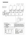
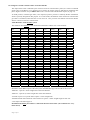
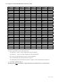
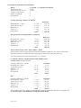
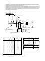
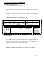
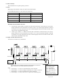
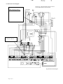
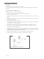
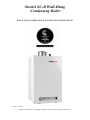
Strebel SC-B Wall-Hung
Condensing Boiler
INSTALLATION OPERATING & MAINTENANCE INSTRUCTIONS
Version 3.1-Jul/06
Strebel is not liable for any damage caused by incorrectly following these instructions.
1.
SAFETY GUIDELINES
4
2.
TYPICAL SYSTEM LAYOUT
5
2.1.
Single Boiler layout & quick Reference
5
2.2.
Cascade Boiler layout & quick reference
6
3.
TECHNICAL DATA S-CB BOILERS
7
4.
INTRODUCTION
8
4.1.
Operation of the S-CB Boiler
8
4.2.
Controls
8
4.3.
Frost Protection
8
4.4.
Cascade Control
8
5.
ACCESSORIES
9
6.
INSTALLATION OF THE S-CB
9
6.1.
Unpacking
9
6.2.
Select the position of the boiler
6.2.1
11
6.3.
Mounting the boiler
12
6.4.
Air Supply & flue gas discharge types
12
6.5.
The air inlet and gas outlet system
12
6.5.1
SC-B Flue resistance table and example calculation 1
13
6.5.2
Single & cascade table air inlet resistance
14
6.5.3
Single & cascade table flue resistance
15
6.6.
Example flue resistance calculation 2
16
6.7.
Example flue resistance calculation 3
16
6.8.
Condense water drain
17
6.9.
Central heating material
17
6.10.
7.
Important provisions
10
6.9.1
Central Heating circuit
17
6.9.2
The expansion vessel
17
6.9.3
S-CB Internal Pump
18
Low loss header & cascade layout
18
INSTALLATION INSTRUCTION FOR THE ELECTRICIAN
19
7.1.
Connecting to the mains power supply
19
7.2.
Connector strip
19
7.3.
Polarity sensitivity
23
7.4.
Fuses – Main & boiler internal
23
7.5.
Sample Cascade Electrical Layout
23
7.6.
Electrical Circuit Diagram
24
Page 2 of 51
Page No
8.
PUTTING INTO OPERATION
25
8.1.
Control panel, control knobs & L.E.D.
25
8.2.
Sensors
26
8.3.
Run and Fault Codes and Display meanings
27
8.4.
Display buttons
28
8.4.1
Service Button
28
8.5.
Filling and venting the boiler and system for light up
28
8.6.
Starting the boiler and Commissioning
29
8.7.
8.8.
8.6.1
General
29
8.6.2
Commissioning
29
Adjusting and setting the output
29
8.7.1
Setting the maximum output
29
8.7.2
Setting the minimum output
31
Gas conversion
31
9.
LONG TERM SHUTDOWN
32
10.
LOCK OUT / USER COMPLAINT
33
11.
TROUBLESHOOTING
34
11.1.
Cause of the fault
34
11.2.
Troubleshooting table
36
12.
13
14
INSPECTION AND MAINTENANCE
38
12.1.
General
38
12.2.
Inspection
38
12.3.
Maintenance
39
LPG Settings
SCB 60 to 120
40
SCB 150 to 180
41
EXPLODED VIEWS AND SPARES
42
14.1Burner, fan, gas pipe, heat exchanger, casing S-CB60 – S-CB120
14.1.1Spare Parts S-CB60 – S-CB120
14.2.Burner fan, gas pipe, heat exchanger, casing S-CB150 – S-CB180
14.2.1 Spares Parts
S-CB150 – S-CB180
14.3 Pipelines & pumps S-CB60 – S-CB120
14.3.1 Spare Parts S-CB60 – S-CB120
43
44
45
46
47
48
14.4 Pipelines & pumps S-CB150 – S-CB180
49
14.4.1Spare Parts S-CB150 – S-CB180
50
Page 3 of 51
1. SAFETY GUIDELINES
Read all these instructions before commencing installation.
This appliance is free from any asbestos material.
It is the law that all gas appliances and fittings are installed by a competent person (such as a CORGI
registered installer) and in accordance with the Gas Safety (installation and Use Regulations), the relevant
British standards for installation, codes of practice or rules in force and in accordance with the Manufactures’
instructions.
The installation shall also be carried out in accordance with the following regulations, codes and standards:
The Building Regulations issued by the Department of the Environment.
The Building Standards (Scotland) (Consolidation) Regulations issued by the Scottish Development
Department.
The Local Building Regulations and Local water by-laws, the gas services area and the Local Authority
recommendations.
Wiring to the appliance must be in accordance with the IEE (BS 7671) Wiring Regulations the Health
and Safety Document No 635 “The Electricity at Work Regulations 1989” and any local regulations that
apply.
Relevant British standards insofar as the relevant areas that are not covered by these instructions.
BS 5440: Parts 1 and 2 (Flues and Ventilation).
CP 342: Part 2, 1994. Code of practice for centralised hot water supply – buildings other than individual
dwellings.
British Gas Publications: IM/2 purging procedures, IM/5 soundness testing, IM/11, IM/16 Installation of
gas pipe work and boosters.
HSE guidance note PM 5, automatically controlled steam and hot water boilers.
CIBSE, IHVE, Guide ports A, B and C.
IGE/UP/1, IGE/UP/2 and IGE/UP/7.
Failure to comply with these regulations could lead to prosecution and deem the warranty invalid. This
appliance must be installed in accordance with the rules in force and used only in a sufficiently ventilated
space when not in a room sealed application or compartment ventilation as current regulations.
Page 4 of 51
2. TYPICAL SYSTEM LAYOUTS
2.1 Single Boiler Layout
Page 5 of 51
2.2 Typical Cascade Layout
Equipment shown may
not be supplied. Please
see tender for the actual
equipment supplied
Page 6 of 51
3. TECNICAL DETAILS
General
Product Identification Number
Dimensions (h x w x d)
Classification
Gas Appliance Type
Boiler Type S-CB
Water content etc.
Weight (empty)
Gas connection
Co-axial flue connections
Separate Flue Exhaust / Air Inlet
Possible with Adaptor (extra cost)
Power consumption
Protection class
CE 0063 BP3254
835 x 458 x 485
890 x 458 x 670
II2H3P
B23; C13X,C23X,C33X,C43X, C53X, C63X,C83X
60
80
100
120
150
180
3,9
5
6,5
8,3
10,4
12,9
46
73
78
83
92
101
Mm
Ltr
Kg
”
mm
mm
R ¾”
80/125
80-80
W
355
IP40
kW
kW
m³/hr
%
%
%
kW
kW
18-74
20-82
7,9
98
109,5
110
73
20-80
107
<15
23-92
25-102
9,8
98
109,5
110
90
25-100
107
<15
27-111
30-123
11,8
98
109,5
110
109
30-120
107
<15
34-138
38-154
14,7
98
109,5
110
136
36-150
107
<15
43-166
48-184
17,6
98
109,5
110
163
45-180
107
<15
<20
<20
<20
<20
<20
1,5
1,5
Central heating
Nominal input (Nett) 80/60ºC
Nominal input (Gross) 50/30ºC
Gas flow max. (G20)
Efficiency at 80/60ºC
Efficiency 50/30ºC
Efficiency 40/30ºC RAL 61
Nominal output at 80/60ºC
Nominal output at 50/30ºC
Norm efficiency 75/60ºC RAL-UZ61
NO x emission, RAL 61
mg/kWh
14-56
15-61
5,9
97
109
109,5
55
15-60
107
<15
CO emission, RAL 61
mg/kWh
<20
Data
CO2- flue gas
Dew point combustion gas
Temp. Flue gas @ ambient temp 20ºC
Flue resistance capability*
PH value condensate
Available pressure at 25ºC
Max. flow temp.
Min./Max. Boiler Pressure
Sound level at Maximum Output
Average Sound level
R ¾”
R ¾”
R ¾”
R 1”
R 1”
80/125 100/150 100/150 100/150 100/150
80-80 100-100 100-100 130-130 130-130
100-100
130-130
355
355
375
460
460
IP40
IP40
IP40
IP40
IP40
%
°C
°C
Pa
mwk
°C
bar
dBA
dBA
2,5
3
46.0
32.0
47.0
33.0
9
53
85
250* up to 600*
4 to 5,5
1,5
1,5
90
0.5 – 6
48.0
33.0
49.0
50.0
34.0
35.0
Table 1: Data
50.0
35.0
Boiler control includes:
Cascade control for up to 8 boilers ( requires flow temperature sensor at extra cost ) see item G page 8
Remote run & fault indication
0-10 VDC control connection ( requires flow temperature sensor at extra cost )
Control for external calorifier primary pump ( pump not included ) via relay at extra cost ( see page 22)
Weather compensation control (with outside detector at extra cost)
Control for an external pump via relay at extra cost,( see page 22 )external pump not included.
Electronic Ignition.
Boiler output modulated between 25% and 100%,
Page 7 of 51
4. INTRODUCTION
Warning: For trouble free operation of the boiler, and to be assured of the full guarantee, the following
items are required:
A. An automatic air and dirt separator must be installed in the installation and a strainer in
the return also devices as shown on pages 5 or 6.
B. Minimum static water pressure should be more than 0.5 bar.
C. The system is flushed, water tested and additive utilised if required.
D. Boiler auto air vent cap must be open and all system air vents open.
E. Low and high water cut out pressure switches ( usually in the fill unit) connected in the
Boiler volt free control circuit in series with other controls on terminals 13 - 14 or by 0 volt
when using external 0 to 10 volt control by others.
F. Control of Boiler on/off must never be by interruption of the mains supply.
G. When using a common flue the inbuilt cascade control must be used.
These instructions are written for the installer of Strebel products and contain all necessary information on
the installation and adjustment of S-CB boilers. We suggest that you read the instructions before installation
to ensure that all work is done correctly. We suggest that you keep these instructions near the boiler.
4.1 Operation of the S-CB Boiler
The heating boilers from the Strebel S-CB series are central heating boilers with maximum high efficiency.
Such performance is reached by, among other things, using a special heat exchanger made of stainless steel.
The heat exchanger allows flue gases to cool down below condensation point, condensing the flue gases and
releasing extra heat. This has an immediate positive impact on the efficiency, exceeding 100%net calorific.
•
S-CB flue gases have a low temperature (below 85°C), the boiler needs to have a high efficiency
approved stainless steel or plastic flue system .Aluminium flue systems are not allowed to be
connected to these boilers. Adequate drain points must be added to the flue system with a u trap.
4.2 Controls
The Strebel S-CB Boiler adjusts to the demand for heat by using flame modulation and external controls.
That is on the basis of 1) 0 to 10 volt control. 2) Strebel optimiser control 3) Built in weather compensation
with an outside detector. 4) RC or E-BUS .For RC or E-Bus system, see separate booklet.
The boiler control is equipped with:
Control for a DHW Cylinder with a diverter valve or a pump (pump via a relay both not supplied)
Connection for a Heating pump via a relay (pump and relay not supplied)
Connection for a room thermostat, on/off control, optimiser or 0 to 10 volt control (see 4.4.1).
4.3 Frost protection
Frost protection does not protect the system or system pumps. It protects the boiler.
Frost protect the system by fitting devices to link out any time controls. In a frost condition (at 7° Boiler
temperature) the Boiler internal pump starts. When the boiler water temperature falls down to 3°C, the burner
is also ignited. This operation will cease as soon as the boiler temperature has reached 10°C.
4.4 Cascade control
Using the integrated cascade control, a maximum of 8 boilers can be controlled in a cascade configuration.
The Cascade has in-built full logic step control. The Boiler will require a Flow temperature sensor and 2
wires to each boiler in a daisy chain. When using a common flue the cascade control must be used
4.4.1 0-10 VDC connection available
The boiler is equipped to take a 0-10 VDC signal from a controller by others (set at time of commissioning)
with which up to 8 boilers can be controlled in cascade, utilising the built in cascade manager. (0 Volt is
no heat demand.) The Boiler will require a Flow temperature sensor at extra cost.
Page 8 of 51
5. ACCESSORIES
Dependent on the choice of control and hydraulics etc, accessories are available from Strebel at extra cost.
See Page 50 for details
6. INSTALLATION OF THE STREBEL S-CB
6.1 Unpacking
The Strebel S CB includes the following documents and accessories:
•
1 Installation and cascade instructions for the installer.
•
User instruction (incorporated).
•
1 suspension bracket.
•
Fuses and 3 nuts for mounting the burner plate (attached to the front of the gas valve).
•
1 siphon with tightening nut and gasket.
•
Reducing couplings (where required) for flue gas discharge and air supply.
THE BOILER IS SET FOR NATURAL GAS G20.On delivery, immediately check that the Strebel S-CB is
complete and without any defects. Report any damage immediately to the supplier or Strebel Ltd.
.
.
2
6
1
4
5
1.
After removing the carton, the easiest way to take the boiler off the pallet is as follows:
2.
Lift the pallet including the boiler (at the side of the flue outlet) to a vertical position.
3.
The boiler has a polystyrene block, which now supports the Boiler on the floor.
4.
Push the Boiler a little forward, until the pallet is not touching the floor anymore.
5.
The boiler stands now on the flow- and return pipes and the polystyrene block.
6.
Take away the pallet (See also 6.3).
The boiler can now be lifted (unclip and remove the Boiler door before lifting) easily for mounting, by
putting a hand at the lower side of the boiler.
Page 9 of 51
6.2 Select the position for the Boiler
Select a position in the building with adequate access to the front, side and the bottom of the boiler for future
maintenance and servicing. The boiler must have at least 20 mm space at each side.
Boiler Type S-CB 60, 80, 100, 120
Co-axial flue is standard supply on 60kw to 100kw Boilers. Parallel flueing requires an adaptor at extra cost.
Parallel flueing is standard on the SCB 120 .Co-axial adaptor available at extra cost
Co-Axial
connection at the
rear.
Separate exhaust
and air inlet
connections are:
Flue exhaust at
the rear and air
inlet at the front
Parallel Flue
D
D1
S-CB
S-CB
60
80
100
120
80
100
100
130
S-CB
S-CB
60 / 80
100
120
Page 10 of 51
80
100
100
130
Concentric Flue D
D
80/125 mm
100/150 mm
100/150 mm
Boiler Type S-CB 150 and S-CB 180
150kw and 180kw Boilers are supplied with parallel flue connections an adaptor is
available for co axial flue-ing at extra cost
Air inlet
D1
Flue
D
890
Parallel Flue
S-CB
S-CB
D
D1
150
130
130
180
130
130
Co- Axial Flue D
100 /150
130 /150
6.2.1The installation area must have the following provisions:
•
Items listed in 4 page 8 also see drawings 2.1 page 5 and 2.2 page 6.
•
Electrical point with earth connection;
•
Connection to the drains for condensation water or suitable condense removal device
•
A sound wall or suitable mounting. The wall or frame used for mounting the boiler must be able to hold
the weight of the boiler.
•
Both the air supply (if room sealed) and the flues are to be connected to the outside wall and/or the roof.
(see safety guidelines page 4)
•
Install horizontal Flue parts under 1% fall in the direction of the boiler (one centimetre for every
linear metre) complete with extra drain points with a 60mm water trap.
•
The installation area must be dry and frost-free and conform to relevant regulations.
•
Installers are advised to choose a part of their building where slight noise emission will not cause
disturbance.
•
A minimum of 15 mbar gas pressure (and or current regulations) all plant running.
Page 11 of 51
6.3 Mounting the Boiler
Prepare the Boiler for mounting as in 6.1.Determine the positions for the flow and return pipes using the
suspension bracket or a suspension frame, if any. When marking the holes, ensure that the suspension bracket
or frame is level. Drill the holes for the flow and return pipes if required then hook the heating boiler onto the
bracket or place it upon the frame.
6.4 Air supply & flue types
When using multiple SCB Boilers on a common flue the inbuilt cascade control must be used. SCB
Boilers 60kw to 100kw use a co-axial flue. Twin pipe flue-ing utilises an adaptor at extra cost .Boilers 120.
150 and 180 kw use parallel i.e. one air inlet tube and one exhaust tube a co-axial adaptor is available at
extra cost. . All Boilers can be used in a room sealed application or, if the boiler room or fitting space
complies with the relevant ventilation requirements Boilers can be non room sealed I.E. exhaust only,
Providing ventilation as per current regulations is in place. See pages 10 and 11 for flue connections.
Install the horizontal flue parts under 1% fall in the direction of the boiler (one centimetre for every
linear metre). Adequate drain points should be installed throughout long horizontal exhaust runs and
at the base of any vertical flue exhaust run. 60 mm (minimum ) “u” traps should be utilized.
6.5 The air inlet and flue gas outlet system.
The Boiler is ( normally )room sealed, the casing is airtight with air entering through the air supply
connection only. Always ensure the casing is placed over the boiler when the boiler is in operation! The
available pressure for the inlet and flue system is 250
kW
Pa, unless data from the table is being used.
180
A180
180
160
A150
150
N.B.! Install the horizontal flue parts under 1%
fall in the direction of the boiler (one centimetre
for every linear metre). Failing to do so may result
in water condensation building up in the flue gas
tube. In turn, this may cause failure.
140
The impact of the flue to the output
120
A120
120
100
A100
100
80
A80
80
60
A60
60
40
0
100
200
300
400
500
600
The table on the left shows the relationship between
the Boiler output and the resistance of the air inlet
and flue. Up to a resistance of around 250 Pa the
output will be approximately the same as the Boiler
data plate In the event of a greater resistance ( up to
maximum 600 Pa ) this will change the Boiler output
. The resistance and the change of output only affect
the maximum output and not the minimum.
Tip! Remember that possible output changes may
influence hot water production and
transmission/absorption calculations.
Pa
Resistance
up to 250 Pa
300 Pa
350 Pa
400 Pa
450 Pa
500 Pa
550 Pa
600 Pa
Page 12 of 51
Decrease of input
0%
-3%
-4%
-6%
-7%
-8%
-9%
-10 %
6.5.1 Strebel S-CB Flue/Air inlet Resistance table
The output of the boiler is affected by the resistance of the air inlet and flue system. At a resistance up to 250
Pa, the output will be as indicated on the name plate of the boiler. See page 12 for higher flue resistance.
Table 1; Resistance table
(mm)
Co axial
( Twin) Flue gas discharge
(Twin )Air supply
Termina
ls
Co-axial
Item
Boiler S-CB
roof terminal
outside wall terminal
roof terminal
outside wall terminal
straight tube/mt
straight tube/mt
straight tube/mt
straight tube/mt
45° bend
45° bend
45° bend
45° bend
90° bend
90° bend
90° bend
90° bend
straight tube/mt
straight tube/mt
straight tube/mt
straight tube/mt
45° bend
45° bend
45° bend
45° bend
90° bend
90° bend
90° bend
90° bend
straight tube/mt
straight tube/mt
45° Concentric bend
45° Concentric bend
90° Concentric bend
90° Concentric bend
125/80
125/80
150/100
150/100
80
100
130
150
80
100
130
150
80
100
130
150
80
100
130
150
80
100
130
150
80
100
130
150
125/80
150/100
125/80
150/100
125/80
150/100
60
25
15
12
10
4
1
0,35
X
2
0,6
0,2
X
4
1
0,35
X
5
2
0,45
X
2,5
1
0,2
X
5
2
0,45
X
8.5
2.5
4.2
1.2
8.5
2.5
Resistance inlet and outlet system [Pa]
80
100
120
150
45
X
X
X
30
X
X
X
30
35
40
X
25
28
32
X
5,5
8
10
15
3
3,5
4
6
0,75
0,8
1
1,2
X
0,3
0,4
0,6
3
4
5
7.5
1,5
1,7
2
2,2
0,4
0,4
0,5
0,6
X
0,15
0,2
0,3
5.5
8
10
15
3
3,5
4
6
0,7
0,8
1
1,2
X
0,3
0,4
0,6
8
12
15
20
3,5
4
6
9
0,8
1,2
1,5
2
X
0,5
0,5
1
4
6,5
8
14
1,7
2
3,2
4.5
0,4
0,6
0,8
1
X
0,2
0,4
0,8
8
12
15
20
3,5
4
6
9
0,8
1,2
1,5
2
X
0,5
0,7
1,1
11.5
X
X
X
4.5
5
8.0
15
5.5
X
X
X
2.2
2.5
4
8
11.5
16
21
X
4.5
5
8
15
*Parallel Roof & wall terminal air inlet/exhaust resistance equals 1 meter straight length of same size
Strebel S-CB Example calculation - Boiler type: S-CB 60
S-CB 60 using a co-axial flue system 125/80, with through the roof terminal.
For the stated output the boiler has 250 Pa fan pressure
Roof terminal = 25
Pa Resistance
25 Pa subtracted from 250 Pa leaves 225 Pa
Each metre length of 125/80 flue has a resistance of 8.5 Pa. 225 divided by 8.5 =26.4
Therefore the above example allows a straight flue run of 26.4 metres.
Reduce this flue run by 1 metre for each 90 degree bend or ½ metre for each 45 degree bend.
See also sample parallel flue calculation on page 16
Install horizontal Flue parts under 1% fall in the direction of the boiler (one centimetre for every
linear metre).
Page 13 of 51
180
X
X
X
X
24
9
2
1,0
12
4.5
1
0,6
24
9
2
1,2
X
12
3
1.5
X
6
1.5
1.8
X
X
3
1.5
X
20
X
10
X
20
6.5.2 Single & Cascade resistance tables of air inlet and flue.
The output of the boiler is affected by the resistance of the air inlet and flue system (as a result of controlled
gas/air ratios in the Boiler). At a resistance up to 250 Pa, the output will be as indicated on the Boiler data
plate. Higher resistance of up to 600 Pa max can be overcome with reduced Boiler output (see page 12).
An under pressure, in the flue gas outlet, is not required, a positive pressure is created by the fan of the Boiler
which is specially designed for this purpose. As a result of this, the diameter of the common air inlet and flue
gas outlet is minimised; while the built in non return air valve prevents recirculation between the Boilers
when 2 or more are used on a common flue.
Table Resistance of the air inlet system
The stated Air inlet diameter is that used between the boilers and the roof or wall terminal.
Transmission
kW
60
90
120
150
180
210
240
270
300
330
360
390
420
450
480
510
540
570
600
630
660
690
720
750
780
810
840
870
900
930
960
990
1020
80 mm
Pa/m
4
7
10
15
24
100 mm
Pa/m
1
2
4
6
9
12
15
18
21
25
130 mm
Pa/m
0.35
0.6
1
1,5
2
2,5
3
4
5
7
8
9
10,5
12
13
14
15
16
18
20
22
23
25
27
28
30
150 mm
Pa/m
180 mm
Pa/m
200 mm
Pa/m
250 mm
Pa/m
0,4
0,6
1
1,4
1,8
2,2
2,6
3
3,4
3,8
5,3
5,8
6,3
6,5
7
8
9
10
11
12
13
14
15
16
17
18
20
21
22
23
25
0,5
0,6
0,7
0,8
0,9
1,1
1,3
1,5
1,7
2
2,3
2,6
2,9
3,3
3,6
3,9
4,2
4,6
5
5,4
5,8
6,2
6,6
7,0
7,5
8
8,5
9,0
9,5
0,8
0,9
1
1,2
1,3
1,4
1,5
1,8
2,1
2,3
2,4
2,5
2,6
3
3,5
4
4,2
4,3
4,3
4,5
4,7
4,9
5,2
5,5
0,65
0,7
0,75
0,8
0,85
0,90
0,95
1
1,1
1,2
1,3
1,4
1,6
1,8
2
Resistance of the different parts of the inlet system: Standard Flue pipe can be used for the air inlet.
*Bend 90° : equal to 1 meter straight tube of the same diameter.
*Bend 45° : equal to 0,5 meter straight tube of the same diameter.
*Cascade T-piece on top of the boiler equal to 1 meter straight tube.
*Parallel Roof & wall terminal air inlet resistance is equal to 1 meter straight length of same size.
* See sample calculation page 16.
Install horizontal Flue parts under 1% fall in the direction of the boiler (one centimetre for every
linear metre).
Page 14 of 51
6.5.3 Single & Cascade Table Resistance of the Flue in Pa/m
SIZE
Output kW
80mm
Pa/m
100mm
Pa/m
60
90
120
150
180
210
240
270
300
330
360
390
420
450
480
510
540
570
600
630
660
690
720
750
780
810
840
870
900
930
960
990
1020
5
8
15
26
2
4
6
9
12
15
20
25
130mm
Pa/m
1
1,5
2
3
4
5,5
7
8,5
10
11
12
13
15
17
19
21
23
27
28
30
150mm
Pa/m
180mm
Pa/m
200mm
Pa/m
250mm
Pa/m
0,6
1
1,5
2
2,5
3
3,5
4
4,5
6
7
8
9
10
11,5
13
14,5
16
17,5
19
20,5
22
23
24
25
26
27
28
29
30
31
0,5
0,6
0,8
1
1,2
1,5
1,7
2
2,3
2,5
3
3,5
4
4,5
5
6
6,3
6,5
7
7,5
8,2
8,4
8,7
9
9,5
10,1
10,6
12
13
14
0,8
0,9
1,1
1,3
1,5
1,7
1,9
2,1
2,3
2,5
2,8
3
3,3
3,7
4,0
4,3
4,6
4,9
5,2
5,6
6
6,4
6,8
7,3
8,0
8,8
X
X
X
X
0,8
0,9
1,0
1,2
1,4
1,5
1,6
1,7
1,8
1,9
2,1
2,2
2,3
2,4
2,5
2,6
Resistance of the different parts of the inlet system:
Bends 90° : equal to 1 meter straight flue of the same diameter
Bends 45° : : equal to 0,5 meter straight flue of the same diameter.
T-piece on top of the boiler is equal to 1 meter straight flue .
Co axial flueing, roof and wall terminal see page 13
Parallel Roof & wall terminal flue resistance is equal to 1 meter straight length of same size
•
See sample calculation page 16
Install horizontal Flue parts under 1% fall to the boiler (one centimetre for every linear metre).
Page 15 of 51
6.6 Example of a Flue Resistance Calculation
Boilers:
Horizontal air inlet:
Vertical air inlet to the roof:
T-pieces over the boilers
Number of bends 90°:
Roof terminal:
4 x 150 kW + 1 x 180 kW; Total 780 kW
5 meter
8 meter
4
2
1
Air inlet: Choosing a diameter of: 180 mm
Horizontal duct , 5 meter
Vertical duct, 8 meter
Bends 90°:x 2
T-pieces: x.4
Roof terminal
5
8
2
4
x 5.8
x 5.8
x 5.8
x 5.8
5.8
Total
Resistance
29.0 Pa
46.4 Pa
11.6 Pa
23.2 Pa
5.8 Pa
116 Pa
Flue gas exhaust Choosing a diameter of: 180 mm
Horizontal flue , 5 meter
Vertical flue, 8 meter
Bends 90°: x 2
T-pieces: x.4
Roof terminal
5 x 8.4
8 x 8.4
2 x 8.4
4 x 8.4
8.4
Total
Resistance
42.0 Pa
67.2 Pa
16.8 Pa
33.6 Pa
8.4 Pa
168.0 Pa
Total resistance of the system : 116 Pa+168Pa = 284 Pa
Total resistance is 284 Pa; higher than 250 Pa,(at which the Boiler output stays the same as stated on the
data plate) therefore according to the table on page 12, the output will be lowered by about 3%.
This means, that the total output will be 780 kW – 3% = 756 kW
6.7 Chosing a diameter of 150 mm for the whole 780 kW system,
Air inlet system: (uses flue material)
Choosing a diameter of: 150 mm
Horizontal duct, 5 meter
Vertical duct, 8 meter
Bends 90°: x. 2
T-pieces: x. 4
Roof terminal
5 x 15
8 x 15
2 x 15
4 x 15
15
Total
Resistance
75 Pa
120 Pa
30 Pa
60 Pa
15 Pa
300 Pa
Flue
Choosing a diameter of: 150 mm
Horizontal Flue, 5 meter
Vertical Flue, 8 meter
Bends 90°: x. 2
T-pieces: x. 4
Roof terminal
Resistance
5 x 23
115 Pa
8 x 23
204 Pa
2 x 23
46 Pa
4 x 23
102 Pa
23
23 Pa
Total
490 Pa
Total resistance: 300+490 = 790 Pa. It is clear, that the resistance is higher than the 250 Pa, even higher than
the maximum 600 Pa; the diameter of 150 mm is too small.
Page 16 of 51
6.8 Condense water drain
The condense water drain is next to the centre at the bottom of the boiler and has a ¾ inch hose discharge.
Connect this flexible hose to the drains via a tundish or oversize waste pipe. Also consider a waste trap.
N.B.!
Use only plastic parts with the condense water drain. Metal lines are not allowed.
Tip!
Blockage of this drain may cause damage to the boiler. The drain connection is correct when the condense
water can be seen flowing away, e.g. using a funnel. Any damage that may occur due to a blockage is not
covered by the warranty.
6.9 Central Heating
If plastic material for the flow and return from the radiators or under floor heating is being used and not
oxygen diffusion proof to DIN standard 4726/4729 a separation between the central heating water of the
boiler and the system will be required, e.g. using a plate heat exchanger. This will prevent contamination of
the boiler heat exchanger with magnetite. If the plastic material is not to the DIN standard failure to provide
such separation will void the warranty of any boiler parts relating to water.
6.9.1 Central Heating circuit
The S-CB has no pressure relief safety valve. This should be fitted in the flow of the system in close
proximity to the boiler (Boiler side of any valves). See pages 5 & 6.
The S-CB has no internal bypass. Low loss headers must be used to allow flow, even when all system valves
are closed.
Tip!
To prevent contamination of the S-CB heat exchanger, it is recommended to thoroughly flush the system
with clean running water prior to first use.
6.9.2 The expansion vessel
Please remember that the capacity of an expansion vessel is chosen or installed to match the capacity of the
central heating system and the static pressure. Fit the expansion vessel in the return of the central heating
system (see page 5 & 6 2.1 and 2.2) Expansion vessels and fill units available at extra cost from Strebel.
Page 17 of 51
6.9.3 Internal Pump
The pump has a speed regulator adjusted to the highest setting: Do not change this setting! The S -CB has a
built-in pump control with a standard 3-minute over run.
The pump will work at top speed when heat is required. When heat is no longer required, the pump will
continue to run for another 3 minutes. The pump and connected three-way valve for the calorifier or external
pump (if fitted) are also activated for one minute every 24 hours. The 24 hour cycle starts as soon as the
power supply to the boiler is activated.
6.10 Low loss header.
Low Loss Headers must be used with the S-CB Boiler
Typical Cascade Layout.
Hidden Detail
AAV
Air & Dirt
seperator
Low loss header
D4
H2
STRAINER
Low Loss Header
FILL
UNIT
D1 Diameter of common
flow & return headers
H3
H1
LSV DOC
EXP
VESSEL
For Low Loss Header size,
Flow and Return size see table.
Low Loss Header & Common Flow/Return
OUTPUT
H1 H2 H3 D4 D1
KW
mm mm mm inch inch
.
60
80
100
120
150
180
240
300
360
420
480
540
600
330
340
345
360
400
445
445
560
680
780
780
780
780
370
380
390
405
450
505
505
620
780
850
850
850
850
465
480
510
565
610
665
665
725
865
980
980
980
980
3
3
4
4
4
5
5
6
8
10
10
10
10
1 1/2
1 1/2
2
2
2
2
2 1/2
2 1/2
2 1/2
4
4
4
4
Boiler Connections Group I
Type
S-CB
60
80
100
120
1 1/2”
1 1/2”
1 1/2”
1 1/2”
3 /4”
3 /4”
3 /4”
3 /4”
Boiler Connections Group II
Type
S-CB
150
180
Note to Design Engineer: See Quotation for equipment supplied.
Page 18 of 51
Flow/Return Gas connection
Flow/Return Gas connection
2“
2“
1”
1”
7. INSTALLATION INSTRUCTIONS FOR THE ELECTRICIAN
7.1 Connecting to the mains power supply
The console has an ON / OFF button to switch the Boiler on or off.
The electrical connections to the S-CB are made via discreet plugs and sockets which are located within the
boiler casing, on top of the control panel.
Connections must only be made using appropriate diameter multi strand flexible cables. Cable entry must
only be via the rubber glanded cable points located at the bottom rear of the appliance: the low voltage
cables are at the left side (top in the drawing below) and the 230 VAC cables are at the right hand side
of the boiler (bottom in the drawing below).
If the boiler is to be room sealed, then care must be taken to ensure the cable entries are reasonably air-tight.
7.2 Boiler Plug & Connector Strip
The stated items may be attached using the available plugs/sockets (use relays for pumps)
Interruption of the mains supply for on/off control must not be used
1
2
Outside
sensor
18 19
C33536
LO
3
4
5
Flow
Sensor
20
HD
6
7
NOT
USED
21
L1
22
N
8
9
L2
Use for 3 way valve
on DHW. Use 2223 for D H W
Primary Pump
24
L1
11
25
26
N
L2
NOT USED
27
L1
13
14
Boiler On/off
( low voltage)
SEE DATA for
RC or E-BUS
28
29
N
L2
Heating Pump
27 - 28
See below
C = Common
HD = Heat Demand/Run
LO = Lock Out
12
+
0 to 10 v
DC in
NOT
USED
DHW
Sensor or
Thermostat
23
10
15
16
Cascade
Bus
Connection
34
35
36
L
N
E
Mains connection
230 AC
Interruption of the
mains supply for
on/off control
must not be used
Connector strip Strebel S-CB
Heating curve
When an outside temperature sensor has been connected, the boiler will respond to the program of weather
compensation (but not when 0 to 10 volt control is used)
Through the parameter menu the heating curve (see page 20) can be set: to do this, use the parameter menu
with the interface cable together with a laptop and the necessary software.
When the outside temperature sensor is connected, the cable terminals “13” and “14” should be bridged; or
an On/Off control should be used. For RC and E-BUS see separate data.
With the temperature button on the display (CH) this heating curve can be shifted with + and - 5°C.
The default for the heating curve of the main circuit is set to K-factor “3,5” See graph page 20
Page 19 of 51
Diagram Outside temperature versus Flow temperature and the K-factor
Flow Temperature
Flow temperature
°C
K-Factor
K=3
K=3,5
K=2,5
K=2
90
K=1,5
80
70
K=1
60
50
K=0,5
40
30
20
30
25
20
15
10
Outside Temperature +
Outside
Outsidetemperature
temperature°C
°C +
5
0
10
-5
-10
-15
Outside Temperature -
Plug
Connection
Description
1-2
Outside
Temperature
Sensor
When an outside temperature sensor is connected, the boiler will be weather
compensated. When no Roomstat or control is connected, the terminals “13 and
“14” should be bridged.
A remote room thermostat with or without time switch can be connected.
The RC or E –Bus (for RC and E-Bus see separate data), with or without built in
room compensation can be used,see other instructions.
When the outside temperature sensor is not connected, the boiler is controlled by the
roomstat or On/Off control (when connected to plug no. 13 and 14 )
3–4
Flow
temperature
sensor
Page 20 of 51
In cascade the flow temperature sensor for the central heating circuit is connected to
these terminals and placed directly on the flow to the installation (after any low loss
header). This flow sensor can work in conjunction with or without an outside
temperature sensor and is required for 0 to 10 v control by others.
5–6
Not used
7–8
Hot Water
Temperature
Sensor
9–10
Not
usedtemperat
ure control
with clock for
secondary
circuit
11-12
0 – 10 VDC
The boiler can be controlled by external control, through a 0 to 10 V signal, by
which 0 Volt is no heat demand and 10 V is maximum output. The DC supply “+”
has to be connected to terminal 11, while the “-“ has to be connected to terminal 12.
A Flow Temperature sensor is also required available at extra cost from Strebel
13-14
Room
temperature
control (with
or without
timer) for the
heating
circuit
These terminals have the following possibilities:
15-16
Cascade
connection
NOTE :
When a Calorifier is connected, a hot water sensor or an on/off thermostat can be
connected. If a sensor is connected, the domestic hot water is set at 60 in the Boiler
and also the water temperature will be shown on the display when active on DHW.
1.
When no on /off control is connected, the boiler temperature is controlled
by the maximum flow temperature, (set by the CH Control Knob on the
Panel). In this case a link has to be used between 13 and 14 .When an
outside temperature sensor is connected, the boiler is controlled through the
heating curve, which can be shifted with the CH Control knob on the Panel.
2.
When an On/Off Control (with or without a timer) is connected, this
control switches the boiler Off, when the desired temperature reaches the
temperature set on such control. (with or without outside temperature
compensation).
When two or more boilers are connected to the boiler control (every boiler control
has a built in cascade manager) each boiler of the cascade has to be connected to the
next boiler, using a two wire bus (cascade connection) terminals. A Flow
Temperature sensor is also required available at extra cost from Strebel.
The cascade control must be used on multiple Boiler systems sharing the same flue.
Page 21 of 51
18-19- Remote Fault Through the use of an external power (e.g. BMS, 230 VAC or 24 v), one Volt Free
20
Lock-out and contact closes in a Lock Out condition and the other on Heat Demand.
remote signal
A BMS, lamp or a buzzer can be connected
for Heat
demand.
HEAT DEMAND
N
LOCK OUT
SUPPLY
21-22-23 Diverter
Valve
primary hot
water circuit
or primary
pump relay
Diverter Valve (3 Port ) for charging a Calorifier
DHW primary pump relay is connected to 22 & 23
When a zone 2 circuit (low temp) is installed, the pump for this circuit has to be
connected to the terminals “N” and “L2” and the PE to the main PE terminal at the
right side of the panel.
24-25- not used
26
secondary
circuit
Mixing Valve for zone 2 (low temp) where the L2 is the Closing hydraulic
connection: (closing when the temperature is rising.)
27-28- HTG Pump
29
Heating pump relay 27– 28
30-31
No
connection
No connection
32-33
No
connection
No connection
34-35- Permanent
36
Supply
Page 22 of 51
The permanent supply is connected to these terminals. This supply must not be
interrupted for control purposes.
7.3 Phase sensitivity
The S-CB boilers are not phase (polarity) sensitive.
7.4 Fuses
Main supply fuse should be 5 Amp, slow blow (Not Strebel supply).
On the PCB. Board, there are 3 auto fuses and 1 mains fuse.
Fuse nr.
Use
Value
F1
Ignition
Automatic re-set
F2
Electronics
Automatic re-set
F3
Electronics
Automatic re-set
230 VAC
Mains
3.15 Amp
Maximum electrical load for the boiler.
a.
For the boiler types S CB60 to S CB120: The total load connected for external diverter valves and or
pumps should not exceed a maximum of 345 Watt (1.45A). Any external pump should be connected
to the boiler via a relay. When the total of the connected pumps and valves exceeds 345 Watt, these
items must be controlled through relays.
b.
Boiler types S CB150 + S CB180: The total load connected for external diverter valves and or
pumps should not exceed a maximum of 255 Watt (1.1A). Any external pump should be connected
to the boiler via a relay. When the total of the connected pumps and valves exceeds 255 Watt, these
items must be controlled through relays.
7.5 Sample Cascade Electrical Layout
All items are not used on every installation.
P2
North Wall
FS
0 to 10 v
see notes
below
See Drawings in the installation operating and maintenance instructions
pages 6 and 20 for full cascade hydraulic layout detail
Notes:
a.
b.
c.
d.
When using 0 – 10 Volt, no room thermostat can be connected
When using 0 – 10 Volt, no bridge is needed for the 13 and 14 connection
When using 0 – 10 Volt, no outside sensor can be connected
When using 0 – 10 Volt, a flow sensor is required on the Heating Flow.
P1 = Inbuilt Boiler pump
P2 = Heating pump
FS = Flow sensor
OS = Outside sensor
RT = Room thermostat
See “ a “
NOTE: See Quotation
for equipment supplied.
Page 23 of 51
7.6 Electrical circuit diagram
60-80-100- 120 KW SINGLE GAS VALVE
150-180 KW DUAL GAS VALVE
PCB with plug numbers
Ferrite
Article no 7427113
Fig 2; Electrical circuit diagram
Page 24 of 51
8. PUTTING INTO OPERATION
8.1 Control panel
Available control elements for the user (also see 8.4 and 8.41 on page 28)
Control Console
1.
Pressure Gauge – 0 to 6 bar .Filling pressure minimum: 0.5 bar.
2.
Control knob with indication: “CH”- Setting maximum Flow temperature
a. With this knob, the max flow temperature of the Central Heating can be adjusted
even when using 0 to 10 volt control.
b. The set temperature will always be displayed unless an outside sensor is fitted.
c. When an outside temperature sensor is connected, the set heating curve temperature will be
displayed: this set heating temperature can be shifted within limits: +10 and – 10°C.
3.
The Display – Shows the set flow temperature or,when 0 to 10 volt control is used the
temperature dictated by the voltage, example 10 volts equals maximum temperature see 2a
above. Where an outside temperature sensor is fitted, the compensated temperature is shown.
Exception: lock out and other faults. When there is a Lock out situation the cause of this Lock out, is
shown in a code on the display. The code is flashing on and off.
4.
Green LED named: Flame. - When the burner is working and firing properly (there is ionisation),
the LED is green; in case there is no Heat Demand, the LED is off.
5.
Press button named RESET: When the display is flashing, there is a lock out situation: by
pressing this button, the boiler will start again: before pressing this button, note the code in the
display in order to record the reason for the lock out see page 27.
6.
Service: Behind the small plastic cap, a plug is available for connection of a cable with interface, for
connection to a computer. This will allow extensive changes to the parameters in the boiler control
when in service mode.
7.
Below the plug, there is a small hole, through which one can push a sharp point (e.g. ball pen), this
will enable the fan speed to be set by turning the CH-knob when in service mode.(for setting the gas
valve see 8.4.1 page 28) When completed, push this small button once again, to return to the
automatic program.
8.
Double pole On/Off switch
O – no mains to the control
I– Control is switched on, and all the components in the boiler.
Page 25 of 51
8.2 Sensors
The boiler uses the following temperature sensors (S3 to S7 when fitted)
S1 =
The flow sensor (on the front left of the heat exchanger).
S2 =
The return sensor (on the rear left of the heat exchanger).
S3 =
Cascade flow temperature sensor.
S4=
NOT USED
S5=
DHW temperature (if fitted).
S6 =
The outside temperature sensor (if fitted).
S7=
NOT USED.
The sensors used in the Strebel S-CB are of the NTC type (negative temperature coefficient) and have the
values shown below:
Temperature
[°C]
0
5
10
15
20
25
30
35
40
45
50
55
60
65
70
75
80
85
90
95
Resistance Sensor 1, 2, 3,
4,5,7 [Ohm]
32550
25340
19870
15700
12490
10000
8059
6535
5330
4372
3605
2989
2490
2084
1753
1481
1256
1070
915
786
Temperature
[°C]
-30
-25
-20
-15
-10
-5
0
5
10
15
20
25
30
35
40
45
Resistance Sensor 6
[Ohm]
171800
129800
98930
76020
58880
45950
36130
28600
22800
18300
14770
12000
9804
8054
6652
5522
Table 2: Sensor table S-CB
If the CH water temperature rises very sharply, the boiler will be blocked by combined action of the supply
and return sensors until the water temperature has fallen again.
Page 26 of 51
8.3 Run and fault Information and Display Meanings
Display Two kinds of information may be displayed:
a. Display codes Steady and not Flashing on and off.
When a code is displayed, it means that there is a heat demand (except the code 0), but the boiler is
not working, example, because the temperature is higher than the set temperature.
After cooling down, in most cases the appliance will automatically start to function again.
Codes not flashing on and off (A2 to O are not faults)
Status
Code on display
Action
Flow temperature achieved
Flow temperature achieved
DHW Calling Boiler off on Temperature
Anti constant recycle ( hunting on & off )
Speed of the fan is too high
Speed of the fan is too low
No call for Heat ( external control
contacts are open & not calling for heat )
A2
A3
A4
A5
A6
A7
O
High limit thermostat is in a short term
(10 Sec) limit condition
C3
The condition may clear on
cooling down (else F2
condition)
Not used
C5
Wait for cooling down
Wait until temperature
decreases
Check cylinder control
Wait for cooling down
Wait until the speed is OK
Switch the external control to
call for heat
b. Codes flashing on and off
A code which is flashing on and off will show that the boiler is in a lock out position, and will not
restart automatically.
The RESET button needs to be pressed, until the flashing lock out code disappears.
Without any adjustments or repairs to the appliance, it is likely that the same lock out will happen
again: so please look at pages 33 to 39 of this booklet, on how to prevent this particular lock out.
Faults with codes flashing indication.
Status
Short circuit on ionisation probe
Code on
display
F0
High limit thermostat condition
Fan speed not correct
No flame after 5 attempts
Flame lift off during heat demand
Flow temperature too high
DHW temperature too high
Return temperature too high
Boiler not operational
Not used
New Parameter programmed correctly
Parameter incorrectly programmed
Burner control out of order
F2
F4
F5
F6
E0
E1
E2
F1
E5
PP
PE
nc
Action. Read page 37
& information below
Check Probe etc
Press Reset Button
Press Reset Button
Press Reset Button
Press Reset Button
Press Reset Button
Press Reset Button
Press Reset Button
Press Reset Button
Program Fault
Press Reset Button
Press Reset Button
Program again
Switch the mains off,
wait 5 seconds then on
Page 27 of 51
8.4 Display console buttons
There are a couple of uses of the buttons and knobs on the display console, namely to adjust settings or to get
information:
-- means the “OFF”
“0” on the display means: “No heat Demand”
On Heat Demand, the required boiler temperature is shown on the Display or domestic water
temperature during DHW demand (DHW if fitted )
8.4.1 Service Button
SERVICE press button.
In order to set the gas-valve for the maximum output as well as for the minimum output, the
appliance has to be put into the SERVICE mode: press a ball pen (or similar) into the small hole
beneath the plastic cap at the right side of the control fascia (see 8.1 page 25).
By turning the CH knob, the speed of the fan can be set between the maximum and minimum speed.
The display will show the speed of the fan e.g. 25 means 2500 r/min.
After 10 min. the boiler switches back to the automatic program: If the setting of the gas-valve is not
complete, press the switch again.
The temperature of all the connected sensors can be shown (without the help of a laptop) on the
display. Press the RESET button, the first temperature is now shown (blinking) together with the
code of the sensor (blinking).
To see the temperature of the next sensor, press again the RESET button.
FL
rE
dH
o
temperature
temperature
temperature
temperature
Flow temperature
Return temperature
Hot water temperature
Outside temperature
8.5 Filling and venting the Boiler and the system in preparation for light up.
Fill the central heating boiler and the heating system using the appropriate filling method. The correct fill
pressure is >0.5 bar max 6 bar
Pay attention to the following aspects in order to prevent corrosion of the CH system:
•
•
•
•
Fill water: if desired use X100 (only) additive to the water for the central heating. The pH value
should be higher than 5 (if not, we suggest you contact Strebel).Test the water. Use additive as required
Thoroughly flush out the central heating system removing all traces of flux and debris.
Ensure that any plastic pipes that are being used are oxygen diffusion-proof in accordance with DIN
4726/4729. If not, separate the boiler circuit and the plastic pipes using a plate heat exchanger
Check the circuit for leaks to prevent oxygen from entering the system.
The boiler has an automatic air vent, at the top of the boiler, this must be opened when the boiler is put
into operation. Check that the A/V screw cap is open by at least one twist. Check all system air vents are
open.
Shortly after putting the boiler into operation, check the filling pressure and add more water to maintain the
required pressure, if necessary .Cure any leaks on the heating and dhw system
Page 28 of 51
8.6 Commissioning
8.6.1 General
Measure the gas pressure in the gas pipe at the pressure nipple (3) of the gas safety valve.
The gas pressure needed for the boiler to work properly under full output is a minimum of 15 mbar (or
current regulations, if greater) all plant running.
3
2
1
2
1
2
3
S-CB 60/80
S-CB 100 / 120
S-CB 150/180
Figure 4; Gas valve(s) Strebel S-CB
NOTE: THE SCREW 2 ON THE GAS VALVE BLOCK SCB 60/80/150/180 IS THE SMALL SCREW AS SHOWN
8.6.2 Boiler Commissioning Light Up
•
•
•
•
•
•
Once the system has been filled, vented, (see 8.5 page 28) tested and everything is in order according
to this manual, connect the central heating boiler to the mains and turn the boiler on..
Make any external control device. IE room stat, control panel etc
When the boiler is turned on, the display will show the requested water temperature (see 8.4 , 8.4.1 )
The burner control will repeatedly give an electronic spark until a flame appears. If no flame appears
after several attempts, check 1), the gas supply. 2), the gas valve has been set correctly.
The Boiler has a built in hot water control, the boiler will first heat up the calorifier (when connected).
Once the calorifier is hot (if fitted), adjust the room thermostat (or make an external control) to a higher
value to start the burner for CH.
8.7 Adjusting and setting the output or when checking or replacing a new gas control valve
Set the valve via measuring the CO2 percentage (LPG is set by CO see page 40 & 41) and gas consumption
rate (The flue may effect the Boiler output see pages 13, 14 and 15) Use this method to set both the minimum
and the maximum output: first set the maximum output and then set the minimum output.
8.7.1 Setting the maximum output
Press with a ball pen (or similar) the SERVICE button (8.4.1) in the small hole beneath the plastic cap at the
right side of the control fascia and then turn the CH knob to give the maximum fan-speed (See table 4. page
30) Measurement of the emissions and CO2 percentage is via the measuring point in the flue gas pipe, (after
unscrewing the plastic cap).
If necessary, turn the adjusting screw 2 (see Figure 4 above) for setting; either anticlockwise to increase the
CO2 percentage or clockwise to reduce the CO2 percentage (see fig 4 page 30). For setting the minimum
output CO2 percentage see page 31 8.7.2 ( LPG is set by CO see page 40 &41).
Boiler
Minimum fan
revolutions (RPM)
For setting CH
Maximum fan
revolutions (RPM) for
setting CH
S-CB 60
S-CB 80
S-CB 100
S-CB120
S-CB 150
S-CB 180
1800
1800
1800
1800
1800
1800
6500
6500
6500
6500
5500
5500
Table 3 Revolutions S-CB
Page 29 of 51
IF the setting takes more than 30 minutes the Boiler will return to auto mode. If so, press the SERVICE
button again. Also for returning to the normal menu press SERVICE.
Set the Boiler via measuring the CO2 percentage (as shown in the table 4a below), and gas consumption rate.
Comment:
Measurement of the emissions and CO2 percentage is via the measuring point in the flue gas pipe, (after
unscrewing the plastic cap).
For gas valve adjustments see illustration on Page 29 Fig. 4
5. Gas consumption.
Boiler
S-CB-60
S-CB-80
S-CB-100
Natural
gas (G20)
0.098 m³
per minute
0.130 m³
per minute
LPG
See 40&41 See 40&41 See40&41 See 40&41
0.164 m³
per
minute
S-CB-120
S-CB-150
S-CB-180
0.196 m³
per minute
0.245 m³
per minute
0.293 m³
per minute
See 40&41 See 40&41
Table 4, Maximum settings
Injector
(Gross)(MJ/m3)
Cal. value Net
(MJ/m3)
CO2 max. Output
(%)
CO2 min. Output
(%)
* measured without casing
Type of gas
Natural gas G 20
LPG
none
none
50.7
76.64
34
88.00
8.8(+/-0.3)*
See LPG
8.5(+/-0.3)*
See LPG
Table 4a Co2 settings
Page 30 of 51
8.7.2 Setting the minimum output
Set the minimum load once the maximum load has been set. In service mode turn the CH knob until the
minimum RPM setting has been reached (20 on the display). In order to set or adjust the minimum load, twist
the screw [1] for the minimum setting. Turn the screw clockwise to increase or anti-clockwise to decrease the
CO2 percentage, (see table 4 a page 30). The gas valve on the S-CB150 and S-CB180, you only are allowed
to set the gas valve on the right hand side. DO NOT ADJUST THE LEFT HAND SIDE GAS VALVE
For Gas Valve Adjustment see illustration on page 29 Figure 4
8.8 Gas conversion
Converting from Nat. gas to LPG:
Boilers with a single gas valve: SCB 60 up to 120 kW: See page 40
Boilers with a two gas valves: SCB 150 up to 180 kW: See page 41
NOTE:
Set LPG by CO emission
Setting LPG CO² % is not important, because it is influenced by the quality of the LPG,
which differs quite a lot; mostly the measured CO² % is roughly between 9.5% and 10%.
High Fire CO: is set to less than 100 ppm CO.
Low Fire CO is set to less than 10 ppm .
Page 31 of 51
9. LONG TERM SHUTDOWN
It is recommended to leave the boiler turned on all year round to prevent frost damage in winter and moving
parts seizing due to corrosion during other times of the year. To switch the boiler off break the frost protected
control circuit (by others) or turn the room thermostat down (minimum power consumption is now assured);
the pump for the central heating and the fan will stop after a short delay.
If the boiler has to be put out of operation, the following action must be taken:
•
Close the gas cock.
•
Remove the electrical plug from the wall socket, or switch off the mains-power.
•
In the event of possible frost damage: drain both the boiler and the system.
When draining the boiler, drain the system first. Then open the two drain cocks of the boiler.
•
•
•
Put the O/I switch to position “O” and the On / OFF switch in position “OFF”.
Isolate at local isolation.
Open the filling and drain valve of the central heating system and the boiler drain valve on the right- and
left-hand side of the boiler.
Page 32 of 51
10. LOCK OUT
As the burner control goes into Lock Out, the display will show a code (see also 8.3 page 27) which
corresponds with the cause of the error; the table below shows the errors.
Only by pressing the “Reset-button” the boiler can be reactivated.
Meaning
Code on
Display
F0
F2
F4
F5
F6
E0
E1
E2
E4
E5
Possible cause of the Lock Out
See fault numbers Page 34 to 37
18; 35; 61
4;5;21;23;24;29;30;42;46
7;8;9;13;19;39;40;41
10;11;16;18;22;25;35;
10;12;16;22;25;26;32;44
4;5;23;29;46
3;4;21;24;25;38;43;55;
4;5;23;29;46
3;4;21;24;25;38;43;55;
1;2;3;4;21;24;30;43;46;51;55;63;
New Parameters programmed correct
Parameters incorrectly programmeerd
Burner Control has malfunction
No communication (in cascade mode)
PP
PE
nc
nc,
Burner defect
H1
Press Re Set Button
Revise programme
Switch power off then on
Check cables to all boilers and Bus
address numbers
Press reset button
Short Circuit in Ionisation Circuit
Limit Temperature
Wrong Fan speed
No Flame after 5 Ignition attempts
Flame lost (4 times) during running
Flow sensor shorted or interrupted
Return Sensor short/interrupted
There are several faults or complaints that the display is unable to convey.
Some of these faults or complaints are:
Complaint
a.
b.
c.
d.
e.
f.
g.
h.
i.
j.
k.
l.
The building is not warming up but the boiler is working
Noisy ignition
Burner of the boiler is continuously on, but the CH water is not warming
up
Room thermostat demanding heat, but boiler is not firing
Burner of the boiler is continuously on; building is getting too hot
Boiler is very noisy during CH operation
Tops of radiators are insufficiently hot
ON DHW, the water is cold
Temperature of the DHW is far too hot
ON DHW, the water remains below 60°C
ON DHW, the boiler is very noisy
Fault after replacement of the burner control
Cause of the fault
(see page 34 to 37)
45;53;54
16;35
45
1;42;52
2
29;46;66
55
24;56
51;57
51;58
23;59
60
Table 5; Other faults
Page 33 of 51
11. TROUBLESHOOTING
11.1 Cause of the fault
The faults listed on page 33 may have the following causes.
Table 6: Causes of faults
1.
2.
3.
4.
5.
6.
7.
8.
9.
10.
11.
12.
13.
14.
15.
16.
17.
18.
19.
20.
21.
22.
23.
24.
25.
26.
27.
28.
29.
30.
31.
34.
35.
36.
37.
38.
39.
40.
41.
42.
43.
44.
45.
Page 34 of 51
Room thermostat incorrectly connected.
Room thermostat not turning off, short-circuit in cable.
Sensor causing short-circuit in cable or internally.
Pump not running; got seized
Water pressure in the CH system too low. on external pressure gauge
Water pressure in the CH system too high. on external pressure gauge
Fan not connected (unplugged).
Fan has been damaged or dirty
Fan is defective
Gas valve not open.
Gas pressure is too low.
Gas pipe diameter is too small.
Fuse F3 defect
Fuse F4 defect.
Fuse F5 defect.
Gas valve setting for lowest RPM incorrect.
Gas valve is not or incorrectly connected to the power supply.
Ignition cable incorrectly connected
Transformer defect.
Connecting plug to gas valve connected incorrectly, or moist inside
Power plug of the pump connected incorrectly.
Siphon blocked.
Opening and closing manual de-aerator, after bleeding.
Three-way valve has been damaged.
Too much resistance in the flue system, or flue system is restricted or blocked.
Flue system having a leak to the inlet system; re-circulation of flue gas, only in case of concentric
flue connection.
Heat exchanger blocked (insufficient circulation).
High-limit thermostat defect (insufficient circulation).
Maximum load is too high.
Burner control defect.
Ignition electrode defect (porcelain cracked), incorrect distance to burner control
Moist or wet on the gas valve cables.
Moist or wet on the PCB of the burner control.
Moist or wet in the pump wiring.
Moist or wet in the fan and/or the fan connection.
Fan plug connected incorrectly.
Plug connected incorrectly.
Damaged connecting cable.
Sensor defect.
Flue gas circulation from behind the heat exchanger.
Flow or DHW leakage
Causes of faults table (cont’d)
46.
Setting of the RPM switch of the pump is too low.
47.
Sensors changed around (return sensor -S2 and hot water sensor S5).
48.
Fuse F1.Automatic re set
49.
Fuse F2 Automatic re set
50.
Line voltage 230 VAC.
51.
Parameter(s) in the installer program entered incorrectly.
52.
Open control, room thermostat, or common thermostat connected to an incorrect connector strip
port.
53.
Pulse width program in the installer menu incorrectly programmed; or steps are too long.
54.
Clock program of the clock thermostat should start earlier in the morning.
55.
Flow and return on the boiler have been changed around.
56.
Cable or plug to the three-way valve connected incorrectly.
57.
Priority sensor (S3) not placed correctly, or defect.
60.
Cable harness connectors incorrectly mounted on the PCB.
61.
Gas safety valve defect.
62.
After programming using the computer, confirms the new settings.
63.
Incorrect parameters or values outside the range of the program have been entered.
64.
The burner control is frequently checking the supply voltage.
65.
Mechanical defect in the Reset key when “H” is blinking; when the H is not blinking, the burner
control is defective.
66.
Gas valve is not correctly adjusted at maximum input.
Page 35 of 51
11.2 Troubleshooting table
Numbers are corresponding with Table 7
Table 7: Troubleshooting table
1.
2.
3.
4.
5.
6.
7.
8.
9.
10.
11.
12.
13.
14.
15.
16.
17.
18.
19.
20.
21.
22.
23.
24.
25.
26.
27.
28.
29.
30.
31.
Page 36 of 51
Check cable or replace the cable, check that the cable is connected to the correct connector strip.
Replace room thermostat or cable: has the correct thermostat been used?
Replace sensor or find cable fault.
Try and loosen the pump spindle, or replace the pump drive.
Add water and detect leak, also check the expansion vessel for leaks.
Too much water added; drain, check the pressure in the expansion vessel for correct air cushion
pressure(only check with 0 water pressure) replace the expansion vessel if defective
Place the plug: with the cables on the fan side.
Clean the fan blades.
Replace the fan
Open gas valve.
Check line and gas meter, make a resistance calculation, as required.
Change gas lines.
Check fuse F4- check all 230 V connections: pump, PCB.
See paragraph 6.4
Check the cabling using the wiring diagram, check the connection to the gas valve, be aware of
moister
Check cable for short-circuit, overheating, nearby or jammed between steel plate; check spark
plug cap for cracks, replace cap.
Replace the burner control.
Moister trapped, check the cable sockets which should fit tightly around the plug pins, check the
position of the cable socket, possibly adjust before the plug slides in.
Check that the plug(s) are fitting tightly.
Open the drain line (left-hand side of the boiler) by unscrewing the cap. Keep a jug on hand to
catch the amount of water drained. Poke through the line using a pen, moving left upward and
right upward. Take the burner unit from the boiler as required and pour some water in the heat
exchanger to rinse out the siphon.
Bleed the unit, not only the boiler itself but the entire system – in the event of such overall deaeration it is recommended to remove the 230 V off the boiler from the wall switch as the CH
pump should not be activated during the process.
Check the cut-off valve of the three-way valve. Take the pump motor out by unscrewing the four
fastening screws. Check the valve on the inside of the housing.
The driving motor can be removed by taking out the fastening screw at the front of the housing
(right bottom) and subsequently pressing the “snap in” lug on the side of the housing, just above
the motor, while pressing the motor down at the same time.
Check the air inlet and flue lines for blockage.
Check the inlet and flue system.
See 26.
REPLACE THE BOILER
Replace the high-limit thermostat by unscrewing from the brass nut: no draining is needed (do not
remove the brass nut).
Go over the settings as outlined in paragraph 6.6.1.
Troubleshooting table (cont’d)
34. Remove the burner control from the boiler by:
a. Removing the ignition cable from the electrode and remove the cable from the console
b. Removing the wiring from the spiral – 1X2-pole plug, 1X8-pole plug and the 230V-plug (right
side of the front). Unscrew the facia (4x) remove the burner control and replace it.
35. Replace, when bending: take care as bending near the burner plate may give a risk of cracking.
36. Dry, using a hairdryer as necessary, and check if working. Replace as necessary.
37. See 36.
38. See 36. Remove the connection and blow dry, using a hairdryer.
39. See 36. Remove the connection and blow dry, using a hairdryer.
40. The plug/ wire connection must point to the outside of the fan and one side should fit into the groove
on the PCB.
41. Check plugs and fit into one another correctly.
42. Check cables for possible damage or being trapped, and replace as required.
43. Check connections, or replace sensor.
44. Check the seal of the heat exchanger on the flue gas casing, and replace as required, fit a new rotary
lip seal.
45. Check flow and DHW-Pipes.
46. Turn the pump switch to position 3.
47. Check if the sensors are interchanged.
48. Possibly replace the fuse (must be a reason for the defect); there is no spare fuse present, see
diagram on page 26.
49. Possibly replace fuse (must be a reason for the defect); there is no spare fuse present, see diagram on
page 26.
50. Check the mains lead, the wall box for voltage; main fuse
51. Check the programmed parameters
52. Check the type of room thermostat and the indication on the sticker of the connector strips on the
boiler.
53. Change the pulse width program; see parameter manual.
54. Change the “wake-up” times of the clock thermostat.
55. Flow is on the left-hand side of the boiler; return on the right-hand side.
56. Check three-way valve including cables on the valve as well as on the connection strip.
57. Check the sensor on the calorifier.
60. It may occur that the 18-pin PCB plug moved up one pin too far; this may cause a fault in the
communication between the wiring and the pins: check both the left and the right-hand side of the
PCB plug to make sure the plugs are placed correctly.
61. A defect to the gas block usually has one of two causes: the electric coils are defective, or an internal
defect on the gas valve. In either case it would be recommended to replace the entire gas valve.
63. Use the correct software (please check) for programming. Also, do not exceed the value limits. Try
to reprogram.
64. Check the supply voltage using a universal meter; if the voltage is correct (should be between 190
and 250 Volt) replace the burner control.
65. In order to restore the Reset key, take the display from the plastic spacers and try the proper working
again. If negative, replace the display. If the display works outside the boiler, check that the key has
sufficient space under the plastic cover (not being blocked); make room.
If the letter “H” is not blinking, replace the burner control.
66. Re-adjust the gas valve as per the instructions.
Page 37 of 51
12 INSPECTION AND MAINTENANCE
12.1 General
The boiler requires inspection at least once every 12 months.
As a rule of thumb, inspection/maintenance is to be carried out when the boiler generates a number of similar
error codes.
12.2 Inspection (Items J K L Major Service)
An inspection should cover at least the following matters.
a.
Ask the user about any problems with the CH boiler and/or any comments.
b.
Check the system (water) pressure.
c.
Remove the casing of the boiler and check all lines and connections for traces of water and water
leakage.
d.
Inspect the top of the casing and/or the top of the boiler for water leakage or traces of water from the air
supply pipe or the de-aerator.
e.
Open the condense siphon and remove any dirt.
f.
If a laptop computer is available, connect this computer and check the service page for error messages,
starts and failed / successful starting attempts.
g.
Fire the boiler on maximum output, and measure the output and the CO2 percentage.(CO on LPG)
h.
Fire the boiler on minimum output, and measure the output and the CO2 percentage.(CO on LPG)
i.
Note the noise of the CH pump and the fan.
j.
Dismantle the burner unit: remove the 6 x M6 nuts and the ignition cable, and move the burner unit
forward. Remove the plug of the fan cable to the fan when the burner has been pulled half-way from the
combustion chamber Check the inside of the heat exchanger.
k.
Dismantle the air gas mixing box on the suction side of the fan and check the fan blades.
l.
Check the distance from the electrode to the burner; there should be 4 to 5 mm gap.
Figure 3; Distance from electrode to burner S-CB
Page 38 of 51
12.3 Maintenance
Depending on the outcome of the inspection, (preventative) maintenance should be considered.
Reasons may be:
ref. a.
Comments and notes from the customer should be taken seriously and an effort should be made to
find the cause of any deficiencies and problems.
ref. b.
The pressure of the system should be set between 1 and 6 bar: find possible leaks in the system and
have these fixed.
ref. c.
Any leakage must be repaired.
ref. d.
Flue: Find the cause of any water leakage from the air supply (possible cause from the roof
surface). Check the concentric flue and trace any leaks in the flue gas discharge and rectify.
ref. e.
Rinse if the condensed water from the siphon is badly contaminated. Several options are available.
1.
If the burner has already been removed: using a filling hose, pour water into the heat
exchanger (it will eventually reach the siphon).
2.
Adjust the drain line up (if possible) allowing the water to flow to the drain of the boiler.
ref. f.
Act upon the findings from the service screen using the service program or a laptop computer (if
used). and change any parts that may be the cause of these faults,
ref. g.
See under h.
ref. h.
Adjust the gas setting at the gas safety valve, as necessary, under minimum output.
ref. i.
If the CH pump has become noisy (certainly when the pump has been working for more than five
years) it is recommended to replace the pump motor as a precaution.
ref. j.
Never clean the burner itself it is not required If dirt has built up on the inside of the heat exchanger
and/or scale has formed on the inside of the stainless steel pipes, it should be removed using a hard
brush and citric acid do not use a steel brush! Always vacuum any dirt away.
ref. k.
If deposits have built up on the fan blades, carefully clean the blades one by one until the blades are
clean again. Work consistently in cleaning the blades, or else the fan may run irregularly and get out
of balance.
ref. l.
Carefully bend the electrode until the gap is correct 4 to 5 mm or replace (see page 44)
13 INSTRUCTING THE USER
Show the user how to operate the entire system. Above all, the user should be made familiar with all safety
precautions. The user should be told that service and maintenance of the central heating boiler is required
every 12 months or more. Regular service is essential for the safe operation of the boiler. Hand the user the
documents supplied with the S-CB boiler.
Page 39 of 51
Boilers with a single gas valve: SCB 60 up to 120 kW:
- Converting from Nat. gas to LPG:
1.
2.
3.
Turn the small "throttle"(see page 29) screw 2 clockwise about nr. 4 half turns.
press the service switch (with a pen).
The appliance should start: when there is no ignition, open the throttle 2 (anti - clockwise) with
about another half turn.
4. Turn the red control knob on the control panel to the maximum -the speed of the fan will go to
maximum: the colour of the flame should be blue: if yellow, give a little less gas (throttle
clockwise, or when the flame disappears, anti- clockwise).
5. When the flame has the right colour: place the analyser in the measuring hole of the tube not before,
otherwise you could get too much CO in the analyser .
6. Set the throttle screw 2to obtain a reading of about 100 ppm CO Note CO² % is not important it will
be around 9,5 %.
7. Turn the red control knob on the control panel to the left to about 9 O’Clock.
8. Set the screw 2 to obtain about 50 ppm CO.
9. Turn the red control knob on the control panel to the minimum.
10. Set the screw 1 so the analyser shows a CO value lower than 10ppm.
11. Turn the red control knob on the control panel to the maximum, to check the max. CO value, reset
(if required) the CO to less than 100 ppm with help of the Throttle screw.
When fitting a new gas valve:
1. Open the throttle (see page 29) screw 2 (anti - clockwise) completely; then turn screw 8 half turns
clock wise.
2. Press the service switch (with a pen).
• The appliance should start, if there is no ignition, open the throttle (anti - clockwise) about
a half turn.
3. Turn the red control knob on the control panel to the maximum -the speed of the fan will go to
maximum: the colour of the flame should be blue: if yellow give a little less gas (throttle clockwise,
or when the flame disappears, anti- clockwise).
4. When the flame has the right colour: place the analyser in the measuring hole of the tube - not
before, otherwise you could get too much CO in the analyser.
5. Set the throttle screw 2 to obtain a reading of: about 100 ppm CO (CO² % is not important it will be
around 9,5 %).
6. Turn the red control knob on the control panel to the left about to 9 O’ Clock .
7. Set the screw 2 to obtain about 50 ppm CO.
8. Turn the red control knob on the control panel to the minimum.
9. Set the screw 1 to obtain a CO value lower than 10 ppm.
10. Turn the red control knob on the control panel to the maximum, to check the max. CO value , reset
(if required) the CO to less than 100 ppm with help of the Throttle screw.
Page 40 of 51
Boilers with a double gas valve: SCB 150 and 180 kW
- Converting from Nat. gas to LPG:
1.
Disconnect electrically the left hand gas valve, by separating the white plug and contra plug of the
left hand gas valve.
2. Turn the small "throttle" (see page 29) screw 2 (on the right hand gas valve) clockwise about 4 half
turns.
3. Press the service switch (with a ball pen).
4. The appliance should start, if there is no ignition, open the throttle 2 (anti - clockwise) about a half
turn.
5. Turn the red control knob on the control panel to the maximum -the speed of the fan will go to
maximum: the colour of the flame should be blue, if yellow, give a little less gas (throttle clockwise,
or when the flame disappears, anti- clockwise).
6. When the flame has the right colour: place the analyser in the measuring hole of the tube - not
before, otherwise you could get too much CO in the analyser.
7. Set the screw 2 to obtain a reading of about 100 ppm CO. CO² % is not important it will be around
9,5 %.
8. Turn the red control knob on the control panel to the left to about 9 O’clock .
9. Set the screw 2 to obtain about 50 ppm CO.
10. Turn the red wheel to the minimum.
11. Set the screw 1 to give a CO value less than 10 ppm.
12. Turn the red control knob on the control panel to maximum, reset (if required ) the CO at less than
100 ppm with help of the Throttle screw.
Setting after replacing the right hand gas valve:
1.
2.
Open the throttle screw (anti - clockwise) completely; then turn the screw 8 half turns clock wise.
Press the service switch (with a pen) .
Commission the valves as per the commissioning instructions above starting at no 3
Conclusion
Set the Boiler on CO emission
Setting LPG CO² % is not important, because it is influenced by the quality of the
LPG, which differs quite a lot; mostly the measured CO² % is about between 9,5 and
10%) High Fire CO: less than 100 ppm Low Fire CO less than 10 ppm.
Page 41 of 51
14 EXPLODED VIEW DIAGRAMS
Page 42 of 51
14.1 Burner /fan/gas pipe/heat exchanger/casing S-CB 60 / S-CB 80 / S-CB 100 / S-CB 120
Figure 4; S-CB60 / S-CB80 / S-CB100 / S-CB120
Page 43 of 51
14.1 1 Burner /fan/gas pipe/heat exchanger/casing Spare S-CB 60 - S-CB 120
Spare parts S-CB60/120 Duo-Z GB
Article-name
1
4
4
4
5
5
5
5a
6
7
7
8
9
10
10
10
11
12
13
14
15
15
16
16
16
17
18
19
20
20
20
21
22
23
23
24
25
25
26
27
27a
28
29
30
Front panel
Seal ring 80 mm
Seal ring 100 mm
Seal ring 130 mm
Air inlet connection excentr 80
Air inlet connection excentr 100
Air inlet connection excentr 130
Gasket air inlet connection 162/135
Automatic air vent
Seal ring 80 mm
Seal ring 100 mm
NTC sensor
Insulation burner chamber
Heat exchanger 6+3
Heat exchanger 8+4
Heat exchanger 10+6
NTC sensor
Insulation burner door
Burner door
Nuts M6
Electrode
Gasket electrode
Burner 6+3
Burner 8+4
Burner 10+6
Gasket burner inlet pipe
ø5x14 mm Torx screw
M5x12 DIN7985 screw
Gasket inlet pipe & fan A60
Gasket inlet pipe & fan A80 / A100
Gasket inlet pipe & fan A120
Fan
O-ring 70x3 mm
Air gas mixing plate A60 / A80
Air gas mixing plate A100 / A120
Pipe coupling ¾"x ¾"
Gasvalve A60 / A80
Gasvalve A100 / A120
O-ring 33,4x2 NBR
Siphon 90 mm grey
Siphon cleaning tube grey
Flexible tube 600 mm grey
On/off switch black
Display-unit DU-910 incl. cable
Page 44 of 51
Order code
E07.004.023
E07.004.024
E07.004.025
E01.008.002
E01.008.003
E01.008.004
E04.015.008
E07.004.023
E07.004.024
E04.016.287
E07.010.098
E04.016.287
E07.010.093
E03.010.013
E06.010.012
E04.009.014
E07.001.024
E04.012.025
E04.012.026
E04.012.027
E07.001.029
E04.016.132
E07.002.007
E04.016.014
E04.016.281
E07.002.018
E04.016.278
.
31
32
33
34
35
35
35a
36
36
37
37
38a
40
40
40
41
41
41
Article name
Burner control F-910
Tube gland siphon
Tube gland ø38 mm
PG-9 swivel + cable gland 8mm
Adapter concentr. 80/125
Adapter concentr. 80-100/150
Gasket flue gas outlet 194/150
Seal ring 80 mm
Seal ring 100 mm
Seal ring 125 mm
Seal ring 150 mm
Gasket flue gas outlet 194/150
Adapter flue gas outlet 80/80
Adapter flue gas outlet 80/100
Adapter flue gas outlet 100/130
Seal ring 80 mm
Seal ring 100 mm
Seal ring 130 mm
Order code
E04.016.277
E04.010.033
E05.000.064
E01.008.010
E01.008.012
E07.004.023
E07.004.024
E07.004.026
E07.004.027
E01.008.014
E01.008.008
E01.008.009
E07.004.023
E07.004.024
E07.004.027
14.2 Burner/fan/gas pipe/heat exchanger/casing S-CB 150 – S-CB 180
Figure 5; S-CB150 / S-CB 180
Page 45 of 51
14.2.1 Burner/fan/gas pipe/heat exchanger/casing Spare S-CB 150 – S-CB 180
Spare parts S-CB150-180 Duo-Z GB
. Article name
50
51
52
52a
53
54
55
56
56
57
58
59
60
61
62
62
63
63
64
65
66
67
68
68
69
70
71
72
72
73
74
74a
75
76
77
78
79
80
80a
81
Front panel
Seal ring 130
Air inlet connection 130
Gasket air inlet connection 162/135
Automatic air vent
NTC sensor
Insulation burner chamber
Heat exchanger 12+6
Heat exchanger 15+8
Nut M8 DIN934 RVS
NTC sensor
Insulation burner door
Burner door
Nut M6
Electrode
Gasket Electrode
Burner 12+6
Burner 15+8
Gasket burner & air/gas inlet pipe
ø5x14 mm Torx screw
Air-gas inlet pipe 12+6 15+8
M8x8 DIN912 screw
Gasket air-gas inlet pipe & fan A150
Gasket air-gas inlet pipe & fan A180
Fan
O-ring 111x3 NBR
Air-gas mixing box
Gasvalve right
Gasvalve left
O-ring 33,4x2 NBR
Siphon 90 mm grey
Siphon cleaning tube grey
Flexible tube 600 mm grey
Display-unit DU-910 incl. cable
Burner control F-910
Tube gland siphon
Tube gland ø38 mm
Adapter flue gas outlet 100/130
Gasket flue gas outlet 194/150
Seal ring 130 mm
Page 46 of 51
Order code
E07.004.025
E01.008.004
E04.015.008
E04.016.287
E07.010.098
E04.016.287
E07.010.093
E03.010.013
E06.010.012
E04.009.014
E07.001.024
E04.012.028
E04.012.029
E07.001.029
E03.010.016
E04.016.290
E07.002.029
E04.016.014
E04.016.281
E07.002.018
E04.016.278
E04.016.277
E04.010.033
E01.008.009
E07.004.025
14.3.1 Pipes + pump Spare S-CB 60 – S-CB 120
.
90
91
91a
91b
92
Spare parts S-CB60/120 Duo-Z GB page 3
Article name
Check valve ¼"x¼"
Pump complete
Pump motor
Pumphouse 130 mm
Drain 3/8"
Page 48 of 51
Order code
E04.015.005
E04.016.298
E04.016.310
E04.015.064
E04.008.002
14.4 Pipes + pump S-CB 150 / 180
Figure 6; S-CB 150 / S-CB 180
Page 49 of 51
14.4.1 Pipes + pump Spare S-CB 150 – S-CB 180
.
100
100a
100b
101
102
103
Spare parts S-Cb150/ 180 Duo-Z GB
Article name
Order Code
Pump complete
Pump motor
Pumphouse
Drain 3/8"
Pressure gauge 6 bar
Flange with thread 50-2" DIN2566
E04.016.288
E04.016.311
E04.015.065
E04.008.002
E04.015.062
E04.010.120
Accessories
1
2
3
4
5
7
8
9
Item
Outside air temperature sensor : 12kOhm@25°C
External Flow temperature sensor after low velocity header :
10kOhm@25°C, to be wired to the boiler 3 & 4
Calorifier temperature sensor: 10kOhm@25°C; to be connected to the
boiler 7 & 8
Conversion set from concentric to parallel flue and air terminal for
SCB 60 & 80
Conversion set from concentric to parallel flue-air terminal for
SCB80 &,100 &120*
Conversion set from concentric to parallel flue- air terminal for
SCB120 &150 &180
Diverter valve
Mounting frame with flow- , return- and gas tube – see CASCADE Manual
Page 50 of 51
Part no.
E04.016.306
E04.016.304
E04.016.303
E61.001.158
E61.001.159
E61.001.161
E04.000.041
Declaration of Conformity
Under the EC DIRECTIVE on machinery (89/392/EEC, 91/386/EEC, 93/68/EEC) and the EC DIRECTIVE
ON ELECTROMAGNETIC COMPATIBILITY (89/336/EEC, 91/263/EEC, 92/31/EEC, 93/68/EEC)
have been constructed in conformity with the applicable provisions of the
EC DIRECTIVE on machinery and the EC DIRECTIVE on EMC.
Strebel Ltd
Page 51 of 51