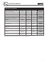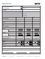
1
Installation systems
EKL/EMK for Vessels and Surfaces
Installation and Operation
Introduction
This BARTEC instruction manual for installation and operation is intended to give you important
information on electric trace heating systems for pipes. Reference is made here only to the use
of BARTEC EKL/EMK single-core heating cables. The contents of this manual are intended
mainly for persons who are familiar with the planning, installation, operation and maintenance
of electric trace heating systems.
Reservation
Technical data are subject to change without notice. Changes, errors and printer’s errors do
not justify claims for damages. For safety components and systems the relevant standards and
regulations are to be observed, as well as the corresponding operating and installation
instructions.
Installation and Operation
Content
1. Introduction
2
2. Important Instructions
2
3. Selection of Heating Cable and configuration
3
4. Storage
3
5. Installation
5.1 Installation preparations
5.2 Installation of the heating cable
4-9
4
5-8
5.3 Installation of accessories
10
5.4 Acceptance and inspection
11
Acceptance certificate
12
6. Temperature Control
13
7. Temperature Limiter
14
8. Heat Insulation
15
9. Power Supply and Electrical Protection Devices
16
10. Inspection and Commissioning
17
11. Operation and Maintenance
18 - 20
12. Proceeding in Fault Cases
20 - 22
12.1 Circuit-breaker trips
21
12.2 Residual current operated circuit-breaker trips
22
12.3 No or insufficient heating capacity
22
12.4 Heating capacity seems to be correct, the pipe temperature, however,
does not reach the desired temperature
22
1
Installation and Operation
1. Introduction
The present BARTEC manual for installation + maintenance is to provide you with important information
on electrical trace heatings for vessels and surfaces.
It exclusively applies to the use of
■ BARTEC-EKL (flexible single-core heating cables) as well as
■ BARTEC-EMK (single-core mineral-insulated heating cables).
The content of this manual is particularly directed towards persons who are entrusted with the planning,
erection, operation and maintenance of electrical trace heatings.
This manual applies to the following BARTEC products:
■ BARTEC EKL heating cables type: 27-582.-5512-....
■ BARTEC EKL light heating cables type: 27-582.-5514-....
■ BARTEC EKL EX heating cables type: 27-582.-5518-....
■ BARTEC EKL standard connection kits type: 27-5673-.1..
■ BARTEC EKL EX termination kits type: 27-5671-.2..
■ BARTEC EMK heating cables type: 27-383.-20../....
■ Pre-assembled EMK heating circuits EX/Standard
Pre-assembled EMK heating loops EX/Standard type: 27-361.-....
■ Installation accessories
The BARTEC warranty only applies if all
provisions and recommendations of the
manual and the product-accompanying
installation and mounting instructions
are strictly adhered to. This particularly
applies to the above-mentioned
instructions.
2. Important Installation and Maintenance Instructions
Observance of the following instructions is imperative when installing and maintaining BARTEC-EKL
and BARTEC-EMK heating cables and their respective installation systems. Non-observance of these
instructions may imply serious hazards for both personnel and system components.
For the installation and maintenance of electrical trace heatings, the respective applicable EC standards
and directives, the national regulations as well as the respectively valid safety regulations must be
complied with. Examples of applicable standards and directives: DIN VDE 100; EN 50110 (1+2); VBG
A2; EN 60519.
Please particularly observe the respective applicable EC standards and directives, the national
regulations as well as the respectively valid safety regulations for the application of electrical trace
heatings in hazardous areas.
Examples of the valid standards and directives for the application of electrical trace heatings in
hazardous areas: EN 60079-14; 94/9/EC Directive; 1999/92/EC Directive; BetrSichV (German
occupational safety regulations).
■ Improper installation of the trace heating and the adjacent system components or heating cable
damage may bear the risk of short circuits and fire during operation.
■ When using an EKL or EMK heating cable in hazardous areas, a temperature monitor as well as a
temperature limiter must always be applied, given no deviating provisions were specified during
the dimensioning and selection of the system.
■ Protect both ends of the single-core heating cable against environmental impact.
■ Junctions or contact points of the single-core heating cables are impermissible as the limit
temperature of the temperature class or the max. permissible operating temperature of the heating
cable would be exceeded.
■ To ensure a proper installation of BARTEC single-core heating cables, we recommend the use of
BARTEC connection systems. Such systems have been specifically developed for BARTEC heating
cables and have been tested and approved by test institutes.
2
Installation and Operation
3. Selection of the Heating Cable and Configuration
Prior to any installation of electrical trace heatings, the installer must check whether the trace heating
has been properly configured. Particularly, the following aspects must be verified:
■ Is an accurate configuration documentation and operation manual available?
■ Does the selected heating cable meet the respective requirements?
This particularly refers to:
- calculated heat loss
- temperature class specified in the type examination certificates
- max. permissible operating temperature
- max. permissible ambient temperature
■ Does the used pipe length exceed or underrun the calculated length?
■ Has a connection system been selected which complies with the requirements?
■ Does further material, which belongs to the trace heating or the adjacent installation, meet the
- electrical
- mechanical
- thermal
- chemical requirements?
■ Has electrical equipment been selected for installation in hazardous areas for which an EC type
examination certificate or a conformity certificate is available?
If a respective configuration documentation is not provided for, we recommend a verification of the
above-mentioned points on the basis of the BARTEC product documentation.
Should any questions arise during the examination of configuration documents, we recommend you to
contact the BARTEC technical department. Thanks to their comprehensive system know-how and a DPsupported configuration, our expert team will provide you with assistance. For the address of our
technical department, please refer to Chapter 12.
4. Storage
Incoming goods
■ Compare the delivery note with the supplied goods.
■ Examine the supplied heating cables and accessory components for possible transport damage.
Storage
■ Store heating cables and connection components at a clean and dry location.
■ During storage, particularly contact with chemicals and petrochemical products must be effectively
avoided.
■ It must be ensured that the heating cables are protected against mechanical damage during storage.
■ The storage temperature is specified in the respective data sheets and must be observed.
■ Even if heating cables and connection components are only shortly stored in damp rooms or at a
construction site, the ends must be effectively protected against humidity (e.g. by installing an
end termination).
3
Installation and Operation
5. Installation
5.1 Installation preparations
5.1.1 Scheduling
■ The installation of the electrical trace heating must be temporally coordinated with other
installation works. This particularly refers to works carried out at the vessels and surfaces to
be heated, the electrical installation and heat insulation.
■ All installation works at the vessels and surfaces must have been completed.
■ Pressure tests as well as material tests of the piping system should have been terminated prior
to installing the electrical trace heating.
5.1.2 Inspections prior to installation
■ Measure the installation resistance at the heating cable shortly before starting the installation
works.
■ Check on the basis of the insulation resistance measuring whether the supplied heating cable length
corresponds to the configuration specifications.
■ Check whether all material required for the installation of the electrical trace heating is available
at the construction site and free of damage.
■ Above all, check whether the identification of the heating cable and the components complies with
the configuration documents (material list) and type examination certificates.
■ Check on the basis of the product-accompanying installation instructions whether all required tools
are completely available.
■ Plan the routing of the heating cable by inspecting the vessel/surface to be heated.
■ Within this context, pay attention to sharp edges and uneven surfaces which may damage the heating
cable and remove them.
■ Varnished and painted vessels and surfaces must be completely dry before starting installation
works.
■ Verify whether the actual surface to be heated complies with the calculated surface.
■ Prior to routing the heating cable, verify whether the vessel/surface dimensions comply with the
dimensions used for design dimensioning. Only cut the heating cable to length after it has been
routed and fixed in accordance with the design dimensioning.
4
Installation and Operation
5.2 Installation of the heating cable
5.2.1 Routing of the heating cable - installation of the fixing accessories
(spacing strip/wire mats)
■ Approx. 25 fixing pins per square meter must be attached to the surface to be heated by means of
spot welding.
■ The points for the welding spots on the surface to be heated must be cleaned by means of an angle
grinder or a similar device (sketch 1).
■ Then, the fixing pins are welded to the surface by means of spot welding (sketch 2).
■ Following this, the welding points and the blank surfaces must be varnished with a corrosion
protection paint. After the coating has dried, the fixing strip can be installed.
Cleaned surface
Fixing pins
Sketch 2
Sketch 1
5.2.2 Installation of the spacing strips
■ The spacing strips (EKL/EMK - sketch 3a) must be attached to the vessel/surface by means of
the spring washers in accordance with the spacings specified in the configuration (sketch 3b).
Alternatively, the spacing strips can be welded to the vessel/surface. When installing the spacing
strips, attention must be paid to sharp edges – risk of injury!
EKL spacing strip
EMK spacing strip
Sketch 3a
Sketch 3b
5
Installation and Operation
5.2.3 Installation of the wire mats
■ The wire mats must be cut to correspond with the respective shape of the surfaces to be heated.
These mats are then fixed with a sufficient number of spring washers (sketch 4a-4c). When
installing the wire mats, attention must be paid to sharp edges - risk of injury! If required, sharp
edges of cutouts must be bent to the inside.
Sketch 4a
Sketch 4b
Sketch 4c
6
Installation and Operation
5.2.2 Installation of the heating cable
■ To unroll the heating cable, use a stable fixture for the heating cable reel.
■ Evenly wind the heating cable off the reel (sketch 5). Avoid extensive pulling as well as bending
and crimping of the heating cable.
■ When rolling the heating cable off the reel, observe that the cable does not run over corners or sharp
edges.
■ Do not step on the heating cable! Do not use the heating conductor as a stepping loop! Do not drive
over the heating cable with a vehicle and keep other people from driving over the cable.
correct
wrong
Sketch 5
EMK
heating cable
■ Starting at the terminal box, the heating cable is routed over the surface to be heated in loops and
fixed by means of the EMK or EKL spacing strip attached beforehand (sketch 5). With the EMK
spacing strip, the heating cable is routed beneath pre-punched lugs which are then bent or
tilted over the heating cable. With the EKL, the heating cable is installed in the provided
terminals (sketch 6).
Prior to routing the heating cable, the spacing strips are fixed to the surface to be heated by
means of fixing pins and locking washers attached beforehand or by means of welding. For
this purpose, the surface is punctually cleaned in accordance with the partitioning to prepare
the fixing pins’ welding by means of the weld clamp (refer to 5.2.1; 5.2.2).
Or fixed to the vessel/surface by means of wire mats installed beforehand. The EKL/EMK
heating cables are fixed to the wire mats by means of binding wire which is twisted together
with the help of combination pliers or a different tool. When using EKL heating cables, also
cable ties can be used for heating cable fixation. It must, however, be observed that the cable
binder/binding wire must not be excessively tightened. The heating cable must still be able
to move in the loop of the cable binder/binding wire (sketch 7).
■ When routing the heating cable, always observe the minimally permissible bending radius!
(5 x external diameter for EKL and EMK).
Example:
ED heating cable
Cable spacing
Cable spacing
= 3 mm
= Factor bending radius x external diameter heating cable
= 5 x 6 mm = 30 mm
■ When routing the heating cable, observe that the heating cable can be re-routed without any
junctions.
■ When routing, consider all fixtures and extensions of vessels and surfaces.
■ Both with the EKL as well as with the EMK, the heating cable terminations consist of transition
sleeves and a connected cold cable. For electrical connection, the ends of the cold cables are
inserted in the terminal box and connected in accordance with the terminal plan.
■ If required by the project, the entire heated surface is covered with aluminium foil after completion
of the installation works (sketch 8).
7
Installation and Operation
Heating cable installation with spacing strip
EKL spacing strip
Sketch 5
EMK spacing strip
Sketch 6
Heating cable installation with wire mats
Sketch 7
Heating cable coverage with aluminium foil
Sketch 8
8
Installation and Operation
Fixing material selection chart
Max. temperature
Width
Roll length
Aluminium self-adhesive tape/EKL
150°C
50 mm
55 m
02-5500-0014
Aluminium foil
400°C
1m
100 m
02-2430-0002
Aluminium foil
400°C
1m
10 m
02-2430-0003
Polyester clamping ring for heating cable fixation (EKL)
105°C
16 mm
1m
03-6500-0100
1 item
03-6515-0203
Self-adhesive tape for heating cable type
Turnbuckle for polyester clamping ring (EKL)
Order no.
Material
Width/Length
P
S/S clamping ring EMK
Stainless steel
3/8''
3/4''
30 m
30 m
03-6510-0203
03-6510-0204
S/S clips clamping ring
Stainless steel
3/8''
3/4''
100 items
100 items
03-6515-0201
03-6515-0202
EKL spacing strip
Stainless steel
10 mm
1m
03-6510-0200
EMK spacing strip
Stainless steel
12.8 x 0.75 mm
30 m
03-6510-0201
Welding pins
Stainless steel
Galvanized CU
1000 items
1000 items
03-5470-0002
03-5470-0001
Spring washers
Stainless steel
Galvanized CU
1000 items
1000 items
03-5479-0001
03-5479-0002
Wire mats
Stainless steel
Galvanized steel
25 m2
25 m2
02-2210-0003
03-5479-0002
Accessories
1m
1m
When selecting the self-adhesive tapes and spacing strips, observe the maximum surface temperature of the heating cable.
Mineral-insulated heating cables are generally fixed by means of stainless steel clamping rings.
9
Installation and Operation
5.3 Installation of accessories
■ Only use BARTEC original accessories to comply with existing technical regulations and approvals.
■ Please observe that the use of BARTEC original accessories constitutes a condition for possible
warranty claims.
■ Carefully observe the installation instructions and technical notes on the package inserts of the
respective accessories. This is imperative for a fault-free installation.
5.3.1 BARTEC system accessories
Beside the heating cable, the following system accessories are usually required for the complete
installation of a heating circuit:
■ Heating cable connection system
■ Cold leads
■ Fixing accessories for the heating cable
■ Heat-insulation ducts
■ Warning labels “electrically heated”
Further system accessories may be additionally required:
■ Heating cable connection
■ Terminal box/connection box
■ Mounting bracket and mounting plate for terminal or connection box
■ BARTEC control units
5.3.2 Further installation instructions
■ Prior to installing the power supply lines, install the heating cable connections.
■ Install terminal boxes in a freely accessible way.
■ When positioning the terminal boxes, make sure that the box entries with cable and heating cable
screw connections do not point upwards.
■ When installing connections, ensure the existing cable paths can be further used.
■ During installation, keep the terminal boxes closed as long as possible to provide protection against
dirt and humidity.
■ Check for a proper establishment of the termination system and the correct functioning of the heating
circuit by measuring the insulation and the loop resistance (Chapter 9).
After the installation of boxes, check:
whether suitable and approved screw connections and filler plugs have been used and whether
they have been properly installed.
for a tight fit of screw connections and filler plugs.
for a tight fit of the box at the mounting bracket.
Ensure whether the requirements stipulated in the type examination certificates have been met.
10
Installation and Operation
5.4 Acceptance and inspection
Caution
Prior to fitting the heat insulation, the installed heating circuits must be
inspected.
Inspection process
■ Prior to the correct routing of the heating cable, particularly observe that
the heating cable fits tightly with the vessel/surface
the heating cable does not show any contact points or junctions
the heating cable does not show any damage
■ Check for a proper installation of terminals, connections and terminal boxes as well as temperature
controllers and sensors (visual check).
■ Check for a proper installation of the limiter sensor (mandatory for heating circuits in hazardous
areas), as well as for the limiter setting.
■ Enter the position of the heating cable as well as that of terminals and connections into the piping
documentation.
■ Measure the insulation resistance in all heating circuits before installing the heat insulations
(Chapter 9).
■ The correct installation and functioning of the electrical trace heating must be confirmed by means
of an acceptance certificate (refer to the following sample form).
■ With stabilised design, verify the conditions stipulated in the project documentation for compliance.
11
Acceptance
Certificate and Operation
Installation
Electrical trace heatings
Sheet
Vessel heatings
Heating circuit
Customer
Date
Order Comm. No.
Project system
BARTEC order No.
Serial No.
Heating circuit No.
Pipe/vessel No.
Building
Product
Heating cable
Type
Installation number
Heating cable length
m
m
m
Voltage
V
V
V
Switch-on
A
A
A
Operation
A
A
A
W/m
W/m
W/m
Cold
Ω
Ω
Ω
Hot
Ω
Ω
Ω
Current
Capacity
Resistance
Insulation resistance- Setpoint: ≥ 5 MΩ
with 1000 V measured voltage
>
Temperature setting
Function check
MΩ
yes
MΩ
>
Function check
no
yes
MΩ
>
Function check
no
yes
Controller
°C
°C
°C
Limiter
°C
°C
°C
Low temperature
°C
°C
°C
EX version
Ex
Ex
Ex
T
T
T
Temperature class
no
Comments:
Above entries verified:
City/Date
BARTEC GmbH
12
Installer
Max-Eyth-Straße 16
D-97980 Bad Mergentheim
Customer
Phone: +49(0)7931 597-0
Fax: +49(0)7931 597-119
Installation and Operation
6. Temperature Control
Selection of a temperature controller
■ For operations with single-core heating cable systems, a temperature controller is always required.
■ When selecting a suitable temperature controller, particularly the following technical data must
comply with the requirements of the respective application:
Rated voltage
Rated current
Temperature control range
Max. permissible temperature/max. permissible sensor temperature
IP protection
Explosion protection, if required
Type examination certificate
■ For reasons of an economical power utilisation, the use of a controller with surface sensor is in
all cases recommendable.
■ Prior to installation, verify whether the applied temperature controller complies with the technical
requirements and the configuration.
Room temperature controller
■ Install a room temperature controller always at the coolest spot of the environment (e.g. north side).
■ Observe the installation instructions of the respective room temperature controller.
Temperature controller with sensing line
■ With surface heatings, the temperature sensor should not be positioned directly at the heating cable
(sketch 9).
■ When fixing the temperature sensor, a sound heat transmission between the sensor and the surface
must be ensured (e.g. by using an aluminium self-adhesive tape or heat transfer compound).
■ Observe the installation instructions of the respective temperature controller.
■ If the position of the temperature controller should not be defined by configuration, please contact
the technical department of BARTEC (Chapter 12), where you will get expert advise.
Further installation instructions
■ During installation, keep the casing of temperature controllers closed as long as possible to prevent
dirt and humidity from intruding.
■ Ensure for a proper fixing of the casing cover and a close sealing.
■ Use suitable screw connections and filler plugs in accordance with the technical requirements and
type examination certificates and check for their impermeability.
13
Installation and Operation
7. Temperature Limiter
For all single-core heating cable systems of monitored design (EKL or EMK), a temperature limiter must
be used in hazardous areas. A limiter permanently switches off the heating circuit upon exceedance of
the limit temperature. The temperature limiter must be installed at the hottest spot.
Maximum surface temperature
Temperature class
450°C
T1
300°C
T2
200°C
T3
135°C
T4
100°C
T5
85°C
T6
The temperature limiter’s task is to avoid an exceedance of the limit temperature in the tracer heating
system, e.g. in case of controller failures or overvoltage, by switching off the heating. Within this
context, the selection and installation of the temperature sensor plays a particularly important role. As
regards the measuring accuracy, the selected sensor mass should be as low as possible.
As a matter of fact, the hottest spot in the system is supposedly at the heating cable itself - usually at
locations where a sound thermal connection of the heating cable to the surface to be heated is hardly
possible, e.g. at valves or flanges.
Artificial hot spot
An artificial hot spot is created by fitting a heat insulation between the heating cable and the surface to
be heated, at which the sensor for the temperature limiter is installed with direct contact to the heating
cable (sketch 9).
■ When installing the temperature limiter, observe that the sensor is positioned at the hottest system
spot. Use aluminium to fix the sensor and the heating cable to each other. To ensure that the
temperature at the artificial hot spot is definitely higher than the heating cable temperature at spots
with minor thermal connection, this hot spot must be dimensioned with approx. double sensor
length.
■ As a result of the unavoidable heat dissipation of the sensor itself, the deviation from the sensor
mass depends on the heating cable mass (proportion of diameters) as well as on the specific heating
capacity (W/m) and must be considered when setting the limiter temperature.
■ Each EKL/EMK heating circuit in hazardous areas must be equipped with a limiter.
■ When using an adjustable temperature limiter, the switch-off point must be set at up to T3 min.
5K and T2 and T1 min. 10K [refer to EN 50019;28] below the maximum surface temperature of the
temperature class.
Example: For T3, limiter setting 195 °C.
14
Installation and Operation
Temperature sensor
Artificial hot spot
Limiter sensor
Sketch 9
8. Heat Insulation
Important instruction
Prior to fitting the heat insulation, verify whether an acceptance inspection of the insulation has been
carried out and documented.
Installation of the heat insulation
The reliable functioning and efficiency of an electrical trace heating essentially depends on a proper and
professional heat insulation installation.
The following factors must be particularly observed:
■ Check for the compliance of the heat insulation (type, insulation thickness) with the configuration.
A heat insulation deviating from the configuration must, in no case, be installed as otherwise a
correct functioning of the trace heating can no longer be guaranteed. This must be particularly
observed for heating systems of “stabilised design”.
■ Install the heat insulation immediately after the installation of the trace heating to minimise the
risk of heating cable damage.
■ Only use dry insulation material. Humidity reduces the efficiency of insulation material and thus
impairs the function of the trace heating.
■ When installing the heat insulation, always take care not to damage the heating cable.
■ Only use BARTEC heat insulation ducts for the ducting of heating and connection cables.
■ Seal the heat insulation at all welds of the steel jacket and entries (valve entries, suspenders).
The entire insulation must be reliably water-proof.
■ After installation of the heat insulation, measure the insulation resistance at all heating circuits
once more to ensure that the heating cable has not been damaged during the installation.
Marking
■ Mark the outer sheath of the heat insulation with “electrically heated” warning labels in clearances
of maximally 3 meters in order to draw the attention of maintenance personnel to the electrical trace
heating.
15
Installation and Operation
9. Power Supply and Electrical Protection Devices
Rated voltage
■ BARTEC heating cables are available for various rated voltages. Respective information is available
in the BARTEC catalogue and from the technical department of BARTEC.
■ Operate the respective heating cable only with the rated voltage provided for. The rated voltage is
stated on the computer print-out of the heating cable layout.
Overcurrent protection device
■ For overcurrent protection, please only use circuit-breakers which comply with the configuration
and the technical BARTEC documents. Deviations therefrom may result in false tripping of the
circuit-breaker and impairment of the efficiency of the overcurrent protection.
■ If protection units other than those specified in the configuration or the technical BARTEC
documents are to be used, please contact the technical department of BARTEC (Chapter 12)..
Residual current operated circuit-breaker
■ Principally, the use of a residual current operated circuit-breaker with 30 mA is recommended.
■ To ensure for the efficiency of this protection measure, a heating cable with protective braiding is
to be used. This protective braiding must be incorporated into the protection measures. this
particularly applies to all trace heatings connected to non-conducting pipes (plastic pipes, coated
pipes) and surfaces.
Caution
■ When implementing the electrical protection measures, the respectively applicable national
technical regulations must be adhered to.
In the Federal Republic of Germany:
VDE regulations, particularly DIN VDE 0100, DIN VDE 0254 and EN 60519.
16
Installation and Operation
10. Inspection and Commissioning
Inspections
Continuing inspections of the trace heating during installation and operation serve the prevention of
additional costs accruing from a belated detection of installation and mounting faults. As the installation
costs for the trace heating and the heat insulation exceed the costs for the heating cable by far, the
following inspection procedures should be consistently followed.
The insulation resistance is to be measured at the following points of time:
a) Pre-inspection
Shortly before commencing installation of the heating cable at the construction site
b) Acceptance inspection
After the heating circuit has been completely installed or prior to applying the heat insulation
c) Final inspection
Immediately after the works at the heat insulation have been completed
d) Commissioning inspection
Prior to switching on the system
Measuring of the insulation resistance
■ This inspection procedure serves the detection of heating cable damage and possible installation
faults of terminals and connections.
■ An insulation test device with a minimum test voltage of 500 V DC and a maximum test voltage
of 2000 V DC is to be used. The insulation resistance should be at least 50 MΩ per heating circuit,
irrespective of the length.
■ Measuring:
The measuring is to be carried out between the heating conductor and the protective braiding.
A further measuring is to be carried out between the protective braiding and the earthed piping.
Acceptance and documentation
■ Upon completion of the installation works (prior to applying the heat insulation), each heating
circuit, if possible in the presence of the client, must be accepted. In accordance with the enclosed
sample report, this acceptance inspection must be documented (=acceptance inspection).
■ All further inspections must also be documented in the form of an inspection report.
■ After the heat insulation has been completely installed, a final inspection of the individual heating
circuits is recommendable.
■ Usually, such inspection lies in the area of responsibility of the client or the final customer (=final
inspection).
Commissioning
■ Each trace heating must only be commissioned if
the acceptance certificates are available for each heating circuit and the fault-free condition
of the trace heating has been confirmed.
the heat insulation has been completely installed and is in a dry state.
it is ensured that the heating circuit is operated in compliance with the data specified by
BARTEC.
Note
Additional heating energy which is required for heating empty or already filled vessels has usually not
been accounted for by the configuration. With system cold starts, you should therefore grant a sufficient
period of time for the vessel to achieve the desired temperature.
17
Installation and Operation
Note
Electrical equipment must only be operated in hazardous areas if
■ it is subject to an EC type examination certificate issued by a testing laboratory listed in
Section 14 of the 76/117/EEC directive and
■ It has been marked with the symbol
by the manufacturer.
■ it complies with the respectively applicable EC standards and directives, the national
regulations as well as with the respectively applicable safety regulations.
Example: German occupational safety regulations (BetrSichV), EN 50014, EN 50019
11. Operation and Maintenance
Operation
■ During the operation of the electrical trace heating, it must be ensured that all system components
are operated in compliance with the operating data specified by BARTEC. This particularly applies
to the observance of maximum temperatures. Operation within the range of these operating data
forms a condition for possible future warranty claims.
System documentation
■ For each system, a complete documentation ranging from configuration, to installation and
commissioning to periodical maintenance works of a trace heating, should be kept.
■ Such documents should include:
Configuration documents
Heat loss calculation
Selection of the heating cable
System plans with heating circuit allocation
Circuit diagrams
Acceptance certificates
Reports on servicing works and interventions with vessels and surfaces, the trace heating
and the heat insulation
Inspection reports
Operating manual
Maintenance
To allow for the best possible safety and reliability of a trace heating system, BARTEC recommends the
implementation of a maintenance program which provides for visual, functional and electrical checks
within specified time intervals.
Important maintenance instructions are listed in the following sections.
18
Installation and Operation
Visual and functional check
■ Carefully check the heat insulation for possible damage, lacking sealings, cracks, outer sheath
damage, lacking heat insulation ducts for heating cables and other cables, intruded water or
chemicals.
If the heat insulation is subject to damage, the heating cable must be checked for possible
impairments.
Damaged heating cables must be replaced by new ones.
Wear parts (e.g. sealings, locking plates, etc.) must be replaced.
■ Check the terminal boxes, connection boxes and casings of temperature controllers for corrosion
damage and possible mechanical impairments. Make sure that all casing covers are correctly
locked.
■ Check the temperature controller’s/safety temperature limiter’s connecting cables and capillary
tube systems for damage and mechanically protected routing.
■ Temperature controllers must be checked for their correct functioning.
■ If no safety temperature limiters with permanently adjusted switch-off value are applied, they
must also be checked for their correct functioning.
Electrical inspection
■ The measuring of the insulation resistance should be considered as an inherent part of the regular
maintenance works.
Inspection intervals
■ With anti-freeze systems, inspections should be carried out annually before the heating period.
■ With systems serving the maintenance of process temperatures, inspections should be carried out
in regular intervals, however, at least twice a year.
Personnel training
■ The regular maintenance works should be carried out by trained and experienced maintenance
personnel.
■ You are recommended to support maintenance personnel with the implementation of new
developments in the fields of application technology and maintenance by training measures.
BARTEC service
■ Apart from establishing complete heating circuits, BARTEC also offers its experienced service
personnel for accruing maintenance works.
Servicing works at the heat insulation and pipings
■ Observe that the system is to be activated prior to each servicing procedure.
■ Ensure not to damage the trace heating system during servicing works at the vessel or the heat
insulation.
■ Make sure that, upon completion of servicing works, the heating circuits, including heat insulation,
are properly and professionally installed in accordance with the configuration.
■ Upon completion of servicing works, carry out a visual, functional and electrical check at the trace
heating and document such checks.
Note
The operation and, consequently, the maintenance of explosion-protected operating equipment
and systems are subject to the respectively applicable EC standards and directives, the national
regulations as well as the respectively valid safety regulations.
For example: EN 50110; German occupational safety regulations (BetrSichV);
German law on device safety (GSGV)
In Germany, the operator must assure that the electrical systems are commissioned, inspected
and maintained in accordance with the German occupational safety regulations (BetrSichV).
19
Installation and Operation
12. Proceeding in Fault Cases
Damage in the heating circuit
■ Never try to repair any damaged heating cables! Immediately replace the damaged part of the heating
cable by a new one (risk of fire!).
■ For servicing the heating circuit, only use original BARTEC components!
(e.g. connections, terminals, sealings, etc.)
Instructions for the rectification of faults
■ If faults occur in the trace heating system, we recommend troubleshooting in accordance with the
following instructions and, if applicable, rectification of the fault.
■ If the rectification measure in accordance with the following instructions is not successful, please
immediately contact the technical department of BARTEC.
Note
For hazardous areas, the following provisions are applicable
Servicing and modification works at electrical systems, during which an explosive
atmosphere can be ignited, may only be carried out with the approval of the plant
manager or a respectively authorised person.
The most important safety measure is to create and ensure for a voltage-free condition
prior to commencing works (refer to the respectively applicable standards and
regulations).
An authorization for the execution of hot works is required and, when working with hot
surfaces/flames, respective protection measures must be taken.
20
Installation and Operation
12.1 Circuit-breaker trips
Possible cause
Measures
1. Underdimensioned circuit-breaker
Check the current load, the overcurrent
protection fuse and the max. current carrying
capacity of the electrical supply line
2. Excessive heating circuit length
3. Switch-on at too low temperatures
(observe configuration data)
4. Faulty RCCB
Replace the RCCB
5. Short-circuit/ground fault at
- terminal
- connection(s)
- connection lines
- heating cable due to damage
Localize and repair faulty terminal or
connection or localize and replace the faulty
heating cable
12.2 Residual current operated circuit-breaker (RCCB) trips
Possible cause
Measures
1. Underdimensioned circuit-breaker
Check the current load, the overcurrent
protection fuse and the max. current carrying
capacity of the electrical supply line
2. Faulty RCCB
3. Short-circuit/ground fault at
- terminal
- connection(s)
- connection lines
- heating cable due to damage
4. Excessive humidity in terminal or
connection(s) due to improper and
unprofessional installation
Localize damp spot(s), replace the terminal
block and dismount affected parts; first, check
and repair casings outside and then casings
underneath the heat insulation
5. Heating cable or connection line damage
Localize the impaired spot and install a new
heating cable or connection line
21
Installation and Operation
12.3 No or insufficient heating capacity
Possible cause
Measures
1. No or insufficient line voltage
Control the line voltage at the heating circuit
infeed and rectify existing faults
2. Heating circuit length is longer than
specified in the configuration
Check heating circuit allocation, routing and
length, re-calculate required heating capacity
a) Connections have not been established
a) Establish connections and re-check the
heating capacity
b) The heating cable has been interrupted
b) Localize and remove the interruption, then
re-check the heating capacity
3. High transmission resistance due to an
improperly installed terminal, connection
Re-install the respective terminal, connection,
etc. and ensure for a correct clamping and
crimping
4. Temperature controller has been
incorrectly connected or set or
wrong sensor position
Correct the wiring or position the sensor
properly
5. Exceedance of the max. permissible
vessel/surface temperature
Check the vessel/surface temperature
6. Heating cable has been subjected to
excessive humidity (e.g. faulty
connection or heating cable damage)
Replace faulty parts
7. Heating cable has been subjected to
excessive temperatures
Replace the heating cable
8. Temperature limiter has tripped
Check and, if required, replace heating circuit
10.4 Heating capacity seems to be correct,
the pipe temperature, however, does not reach the desired temperature
22
Possible cause
Measures
1. Damp heat insulation
Replace the damp heat insulation by a dry one
and ensure for a correct sealing
2. Insufficient fit of the heating cable
routing with flanges, valves and
controls and instruments
Use an additional heating cable by means of
connections while not exceeding the max.
permissible heating circuit length
3. Incorrect setting of the
temperature controller
Correct the controller setting
4. Insufficient thermal dimensioning
Check the dimensioning in co-operation with
the technical department of BARTEC and
observe the recommendations of the BARTEC
planning department
5. The connection line cross-section
underruns the permissible value
(excessive voltage drop)
Use a connection line with a permissible
cross-section
6. Wrong sensor position
Position the sensor correctly
BARTEC protects
people and the
environment
by the safety
of components,
s y s t e m s
BARTEC GmbH
Max-Eyth-Straße 16
D-97980 Bad Mergentheim
Phone: +49 7931 597-0
Fax: +49 7931 597-494
[email protected]
www.bartec.de
UK-D-BEH240604-08/04-BARTEC WerbeAgentur-232188
and plants.