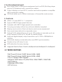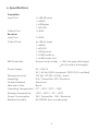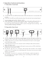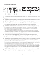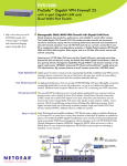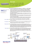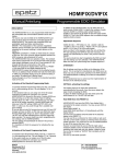
1
CA-USBHUT & CA-USBHU100R HDMI-GIGALAN-TX HDMI-GIGALAN-RX HDMI-GIGALAN-TX CA-USBHUT & HDMI-GIGALAN-RX & CA-USBHU100R Safety Precautions Please read all instructions before attempting to unpack or install or operate this equipment, and before connecting the power supply. Please keep the following in mind as you unpack and install this equipment: Always follow basic safety precautions to reduce the risk of fire, electrical shock and injury to persons. To prevent fire or shock hazard, do not expose the unit to rain, moisture or install this product near water. Never spill liquid of any kind on or into this product. Never push an object of any kind into this product through module openings or empty slots, as you may damage parts. Do not attach the power supply cabling to building surfaces. Do not allow anything to rest on the power cabling or allow it to be abused by persons walking on it. To protect the equipment from overheating, do not block the slots and openings in the module housing that provide ventilation. Revision History Version No Date VR0 20110330 Summary of Change Preliminary Release Table of Contents 1. Introduction ……………………..……………………...…........….……. 1 2. Applications …………………..………………….……...................….. 1 3. EDID Learning …………………..………………….……...................….. 1 4. System Requirements ……………..……….........………............……. 2 5. Features …………………………………………......……........…...…… 2 6. Specifications ………………………………...……..........………....…. 3 7. Operation Controls and Functions ……………...……..............…… 4 7.1 Transmitter’s Front Panel ........................................................ 4 7.2 Transmitter’s Rear Panel .……………………..….......…...….… 4 7.3 Receiver’s Front Panel ............................................................ 5 7.4 Receiver’s Rear Panel .………………...…..…….......…...….… 6 8. D-Sub 9Pin Definitions ….………………….........….............…..…...... 6 9. Connection and Installation ….………………….........…..…..…...... 7 10. Acronyms …...................................................................................... 8 1. Introduction SPATZ HDMI-GIGALAN is another product for transmitting HDMI or DVI over IP networks or extending these signals over a single UTP cable (CAT5e/6/7). The system is using 1000BaseT technology so any structured cabling that has been approved for Gigabit Networks will work for the HDMI-GIGALAN system. Due to a highly integrated ASIC we can offer HDMI over IP in a cost effective way for Real time video. Compression and Latency The transmitter works with a special compression technology that creates fixed data stream of 120 Mbps. The system works with an adaptive motion detection which results in a very high quality for still pictures and an extreme low latency of less than 3ms. If your signal contains motion the system will apply a multi stage prefiltering which will show up as slighty visible compression artefacts. We recommend to test the system with motion video before specifying for such an application. The image quality of typical PC signal up to 1920 x 1200 is exceptional and very difficult to tell apart from a direct connection. We therefore think that this product is well suited for digital signage of any kind or distributing of content with little motion with the advantage of big distances at very low system cost. The HDMI-GIGALAN works best with GIGABIT switches. However they have the ability to detect the network speed and can reduce the transmission rate for 100BaseT equipment. The proprietary network signal can only be decoded by the HDMIGIGALAN-RX and not by any Software decoders or media clients. Point to Point configuration The HDMI-GIGALAN-TX and HDMI-GIGALAN-RX are using the Multicast protocol, which means that units with same multicast adresses can join this group and communicate with each other.This technology is vastly reducing the network load, as only one datastream is created independently of the amount of recipients. If you would like to use the HDMI-GIGALAN on existing networks or switchers they need to support IPv6 or IPv4 and IGMP or CGMP (cisco) protocol. The multicast adress room is 224.0.0.0 to 239.255.255.255. If you intend to use unmanaged switches you have to adjust the transmitters Dip Switches to different adresses. You can have up 16 transmitters and an unlimited amount of receivers in an unmanaged setup. 1 Unmanaged networks will not allow dynamic switching only a changing the multicast adress with the DIP-switches will create a new routing. You can however create virutal paths with this technique if you do not need any dynamic changes. Point to Multi Point configuration/DYNAMIC MATRIX Routing This setup is the right choice for reconfiguring the connections of RX and TX units. With a managed switch all transmitters and receivers would have the same DIP switch setup. The are logically seperated by creating a VLAN for each TX unit. Any RX that joins this VLAN will connect automatically to the one TX source there. This method allows the creation of very large distributed matrices at low system cost. Typciall managed switches can be controlled by RS-232 commands or via Telent commands over one port. So you can create your own app or GUI to control the switch. 2. Applications HDMI, USB, RS-232 & IR Extender Broadcasting system over single CAT5e/6 Long distance data sending with cascade Matrix network system System control over RS-232 and equipment control over IR KVM control 3. EDID LEARNING The HDMI-GIGA-LAN can learn the EDID from the used display and transfer it to the TX device for the source. This assures that there is a controlled EDID table that is representing the capabilities of the used display(s). To learn the EDID in the system, connect TX and RX device directly. Connect the sink to the RX device and then HOLD the VIDEO button when powering the RX device until the Power LED starts flashing. You can now release the VIDEO button the system will reboot and the TX device will now hold the learned EDID until you reprogramm it. If you want only SingleEDID (e.g. 1080p) to be present in the TX device we recommend to use the HDMIFIX as the sink device and learn the SingleEDID from our EDID emulator 2 4. System Requirements Input HDMI and or USB source equipment such as DVD, Blu-Ray player and or PC/Notebook with connection cables. Output display such as HD TV, monitor and active speaker or amplifier with connection cables. CAT5e/6 cable up to 100Ms in between of transmitter and receiver. 5. Features HDMI v1.2 and HDCP v1.1 compliant Support USB 2.0 high-speed devices Operate with USB 2.0 high speed host controllers True plug and play without any driver installation required Display and control of the host device and source equipment Save and share data into a separate room Tested CAT5 cable distance of up to 100 meters or cascade up to as long it require or link up to 16 pairs for matrix system Supports digital display output resolution up to 1920 x 1080@60Hz & WUXGA Automatic display mode detection and DDC synchronization Simple set up with easy to use LED indicators for easy viewing Supports Point to Point, Point to Multipoint and Multipoint to Multipoint 5.1 TESTED SWITCHES Dell PowerConnect 5400 Series (5424, 5448) Dell PowerConnect 6200 Series (6224, 6248) Cisco Catalyst 2960 Gigabit Netgear 7000 Series V2 (GSM7224, GSM7228PS, GSM7248, GSM7252PS) Pakedge SW24-GBM HP Procurve 3 6. Specifications Transmitter Input Port 1 x USB (B type) 1 x HDMI 1 x IR Blaster 1 x RS-232 Output Port 1 x RJ45 Receiver Input Port 1 x RJ45 Output Ports 4 x USB (A type) 1 x HDMI 1 x RS-232 1 x IR Receiver 1 x 3.5Ø Audio In 1 x 3.5Ø Audio Out ESD Protection Human body model: ± 10kV (air-gap discharge) ± 6kV (contact discharge) Power Supply 5V / 2.6A Tx 5V / 3A Rx (US/EU standards, CE/FCC/UL certified) Dimensions (mm) 102 (W) x 95 (D) x 25 (H) / each Weight(g) 214 / Transmitter, 220 / Receiver Chassis Material Aluminum Silkscreen Color Black Operating Temperature 0˚C ~ 40˚C / 32˚F ~ 104˚F Storage Temperature -20˚C ~ 60˚C / -4˚F ~ 140˚F Power Consumption 5W / Transmitter, 12W / Receiver Relative Humidity 20~90% RH (non condensing) 4 7. Operation Controls and Functions 7.1 Transmitter’s Front Panel POWER LINK PAIR SEL LINK HDMI/USB/IR/RS232 to CAT5e/6 Transmitter ① ② ③ ① Power LED: The red LED will illuminate when the device is connected with power. ② Link LED: The LED red will illuminate when the device has received input source single and output display’s data. ③ LINK PAIR SELECT: This dip switch allows user with matrix setting for link up to 16 pairs of the devices with single IP router. Each pair must have the same dip switch setting in order to pair to the right device setting. The factory default setting is at 0000. 7.2 Transmitter’s Rear Panel HDMI IN DC 5V USB IN CAT5e/6 OUT ① ② ③ ④ RS 232 IN BLASTER ⑤ ⑥ ① DC 5V: Plug the 5V/2.6A DC power supply into the unit and connect the adaptor to AC wall outlet. Power LED will illuminate when the power is on. ② USB IN: This slot is to connect with PC/Notebook for input source signal with USB B type cable. ③ CAT5e/6 OUT: This slot is to connect with CAT5e/6 cable with receiver side’s CAT5e/6 input. ④ HDMI IN: This slot is to connect with input source such as DVD or Blu-Ray player with connection cable. ⑤ RS 232 IN: This slot is to connect with D-Sub 9pin female null moden cable from PC’s system for controlling both the input source and output display over RS-232. ⑥ IR BLASTER: This slot is to connect with IR blaster cable included in the package for IR signal sending and controlling the HDMI input source equipment. 5 7.3 Receiver’s Front Panel POWER 1 LINK PAIR SEL 2 USB 3 4 LINK CAT5e/6 to HDMI/USB/IR/RS232 Receiver IR ① ②③ ④ ⑤ ⑥ ① Power LED: The red LED will illuminate when the device is connected with power. ② Link LED: The LED red will illuminate when the device has received output display’s single and input source’s data. ③ IR: receiver: This IR reciever can accept IR signal of the HDMI input source device with frequency between 20~60Hz and can send the signal over CAT5e/6 to transmitter side to control the input source equipment. ④ LINK PAIR SELECT: This dip switch allows user with matrix setting for link up to 16 pairs of the devices with single IP router. Each pair must have the same dip switch setting in order to pair to the right device setting. The factory default setting is at 0000. You can create mutliple groups (upt to 16) consisting of one TX and an unlimited numbers of RX that are using the same LAN. So this is perfect for fixed routed installs for unmanaged IP switches. ⑤ VIDEO MODE: Press this button to switch in between the video and graphic mode. The OSD will display your selection every time when the button is pressed. ⑥ LINK button: Press this button once or twice to allow the receiver to be link up or unlink with the transmitter and the OSD will show "Starting USB" or "Stopping USB" on the HDMI output display. To connect a single transmitter to the desired RX, press the LINK button for 3sec to get the host control of USB on the HDMIGIGALAN-RX. The HDMIGIGALAN con only link one USB connection at a time. Son only one pair of TX and RX can communicate over USB. If there are more than one receiver linked at one TX only the RX that has been linked will make an USB connection. ⑦ USB 1~4: These slots are for users to connect with keyboard, mouse, HDD, USB flash drive and…etc. for USB hub function and KVM usage. 6 7.4 Receiver’s Rear Panel AUDIO HDMI OUT DC 5V RS 232 OUT CAT5e/6 IN IN OUT ① ② ③ ④ ⑤ ⑥ ① DC 5V: Plug the 5V/3A DC power supply into the unit and connect the adaptor to AC wall outlet. Power LED will illuminate when the power is on. ② RS 232 OUT: This slot is to connect with D-Sub 9pin female null moden cable from PC’s system for controlling both the input source and output display over RS-232. ③ CAT5e/6 IN: This slot is to connect with CAT5e/6 cable with transmitter side’s CAT5e/6 output ④ AUDIO IN: This slot is for extra audio input source signal to be connected with 3.5Ø phone jack cable. ⑤ AUDIO OUT: This slot is for external audio output equipment to be connected with active speaker and connection cable. ⑥ HDMI OUT: This slot is to connect with output display such as HD TV or monitor with connection cable. 8. D-Sub 9 Pin Definitions Pin 1 2 3 4 5 6 7 8 9 Define N/C RX TX N/C GND N/C N/C N/C N/C * RS-232 transmission format: Baud Rate: 115200bps Data Bit: 8 bits Parity: None Stop Bit: 1 bit Flow Control: None 7 9. Connection and Installation Transmitter's Rear Panel B HDMI 100m DVD or Notebook Notebook PC or Blu-ray 100m or IP Router 100m Receiver's Rear Panel HDMI Microphone PC Active Speaker TV/Monitor Receiver's Front Panel 3M 30° 3M 30° 7M Keybord 8 Mouse HDD Flash 9