1
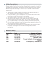
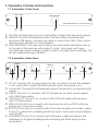
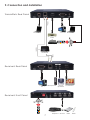
CA-USBHUT & CA-USBHU100R Multi-functioning HDMI/USB/ RS-232 & IR over single CAT5e/6 Transmitter and Receiver Extender Box Operation Manual CA-USBHUT & CA-USBHU100R Disclaimers The information in this manual has been carefully checked and is believed to be accurate. Cypress Technology assumes no responsibility for any infringements of patents or other rights of third parties which may result from its use. Cypress Technology assumes no responsibility for any inaccuracies that may be contained in this document. Cypress also makes no commitment to update or to keep current the information contained in this document. Cypress Technology reserves the right to make improvements to this document and/or product at any time and without notice. Copyright Notice No part of this document may be reproduced, transmitted, transcribed, stored in a retrieval system, or any of its part translated into any language or computer file, in any form or by any means - electronic, mechanical, magnetic, optical, chemical, manual, or otherwise - without express written permission and consent from Cypress Technology. © Copyright 2011 by Cypress Technology. All Rights Reserved. Version 1.0 March 2011 Trademark Acknowledgments All products or service names mentioned in this document may be trademarks of the companies with which they are associated. Safety Precautions Please read all instructions before attempting to unpack or install or operate this equipment, and before connecting the power supply. Please keep the following in mind as you unpack and install this equipment: Always follow basic safety precautions to reduce the risk of fire, electrical shock and injury to persons. To prevent fire or shock hazard, do not expose the unit to rain, moisture or install this product near water. Never spill liquid of any kind on or into this product. Never push an object of any kind into this product through module openings or empty slots, as you may damage parts. Do not attach the power supply cabling to building surfaces. Do not allow anything to rest on the power cabling or allow it to be abused by persons walking on it. To protect the equipment from overheating, do not block the slots and openings in the module housing that provide ventilation. Revision History Version No Date Summary of Change VR020110330 Preliminary Release VR1 20110609 Add EDID Function VR2 20110913 WUXGA @ RB VR3 20120204 Power adaptor, Dimensions & Weight VR4 20120416 IR Frequency & Distance Table of Contents 1. Introduction ……………………..……………………...…........….……. 1 2. Applications …………………..………………….……...................….. 1 3. Package Contents ………………………...........……….................… 1 4. System Requirements ……………..……….........………............……. 2 5. Features …………………………………………......……........…...…… 2 6. Specifications ………………………………...……..........………....…. 3 7. Operation Controls and Functions ……………...……..............…… 7.1 Transmitter’s Front Panel ........................................................ 4 7.2 Transmitter’s Rear Panel .……………………..….......…...….… 4 7.3 Receiver’s Front Panel ............................................................ 5 7.4 Receiver’s Rear Panel .………………...…..…….......…...….… 6 8. D-Sub 9Pin Definitions ….………………….........….............…..…...... 6 9. Connection and Installation ….………………….........…..…..…...... 7 10. Acronyms …...................................................................................... 8 4 1. Introduction With HDMI & USB over CAT5e/6 connectivity are becoming popular nowadays. The growing need for their flexibility has likewise risen in demand. The HDMI & USB over a CAT5e/6 transmitter and receiver box solution is developed for any household and/or commercial environment. This pair of devices allows HDMI and or USB host device to send data within a 100-meters distance while offering expandability for up to 4 USB outputs to perform tasks. In addition, this pair of devices can also save data from the output port devices or allow remote control through the display side even when there's 100 meters apart separating the devices. Furthermore, this pair of devices includes extra functions like IR, line-out and microphone features that allows user to enjoy control over distance and audio sound over favor audio equipments. Moreover, the device allowing user with cascade with the same family type of device to extend the transmission distance up to as long as it demand and without signal loss or delay, or with multi pairs of the extender box up to 16 for matrix usage from a IP for data sharing within the connected device of sources and displays. The HDMI & USB over a CAT5e/6 transmitter and receiver box are the ideal choices to your HDMI & USB extension and data sharing needs. 2. Applications HDMI, USB, RS-232 & IR Extender Broadcasting system over single CAT5e/6 Multimedia display and multi-data sharing Long distance data sending with cascade Matrix network system System control over RS-232 and equipment control over IR KVM control 3. Package Contents HDMI & USB over single CAT5e/6 Transmitter HDMI & USB over single CAT5e/6 Receiver 5V / 3A DC power supply x 2 IR Blaster x 1 Operation manual 1 4. System Requirements Input HDMI and or USB source equipment such as DVD, Blu-Ray player and or PC/Notebook with connection cables. Output display such as HD TV, monitor and active speaker or amplifier with connection cables. CAT5e/6 cable up to 100Ms in between of transmitter and receiver. 5. Features HDMI v1.2 and HDCP v1.1 compliant Support USB 2.0 high-speed devices Operate with USB 2.0 high speed host controllers True plug and play without any driver installation required Display and control of the host device and source equipment Save and share data into a separate room Tested CAT5 cable distance of up to 100 meters or cascade up to as long it require or link up to 16 pairs for matrix system Supports digital display output resolution up to 1920 x 1080@60Hz & WUXGA@RB Automatic display mode detection and DDC synchronization Simple set up with easy to use LED indicators for easy viewing Data transmission rate 1G bit/s Can cascade over Giga Ethernet hub base on TCP/IP 2 6. Specifications Transmitter Input Port 1 x USB (B type) 1 x HDMI 1 x IR Blaster 1 x RS-232 Output Port 1 x RJ45 Receiver Input Port 1 x RJ45 1 x 3.5Ø Audio In Output Ports 4 x USB (A type) 1 x HDMI 1 x RS-232 1 x IR Receiver 1 x 3.5Ø Audio Out ESD Protection Human body model: ± 10kV (air-gap discharge) ± 6kV (contact discharge) Power Supply 5V / 3A (US/EU standards, CE/FCC/UL certified) Dimensions (mm) 180 (W) x 110 (D) x 25 (H) / each Weight(g) 382 / Transmitter, 384 / Receiver Chassis Material Aluminum Silkscreen Color Black Operating Temperature 0˚C ~ 40˚C / 32˚F ~ 104˚F Storage Temperature -20˚C ~ 60˚C / -4˚F ~ 140˚F Power Consumption 5W / Transmitter, 12W / Receiver Relative Humidity 20~90% RH (non condensing) 3 7. Operation Controls and Functions 7.1 Transmitter’s Front Panel LINK USB LINK PAIR SEL HDMI/USB/IR/RS232 to CAT5e/6 Transmitter ① ② ③ ① This LED will illuminate when the transmitter is linked with receiver's signal. ② USB LED: This LED will illuminate when the transmitter has linked with receiver's USB signal. User are only able to control the USB in (the source device) when this LED is not illuminated. ③ LINK PAIR SELECT: This dip switch allows user with matrix setting for link up to 16 pairs of the devices with single IP router. Each pair must have the same dip switch setting in order to pair to the right device setting. The factory default setting is at 0000. 7.2 Transmitter’s Rear Panel POWER DC 5V ① ② HDMI IN USB IN CAT5e/6 OUT ③ ④ ⑤ RS 232 IN IR BLASTER ⑥ ⑦ ① DC 5V: Plug the DC power supply into the unit and connect the adaptor to AC wall outlet. Power LED will illuminate when the power is on. ② Power LED: The red LED will illuminate when the device is connected with power. ③ USB IN: This slot is to connect with PC/Notebook for input source signal with USB B type cable. ④ CAT5e/6 OUT: This slot is to connect with CAT5e/6 cable with receiver side’s CAT5e/6 input. ⑤ HDMI IN: This slot is to connect with input source such as DVD or Blu-ray player with connection cable. ⑥ RS 232 IN: This slot is to connect with D-Sub 9pin female null moden cable from PC’s system for controlling both the input source and output display over RS-232. ⑦ IR BLASTER: This slot is to connect with IR blaster cable included in the package for IR signal sending and controlling the HDMI input source equipment. 4 7.3 Receiver’s Front Panel LINK LINK PAIR SEL 1 ② USB 3 4 CAT5e/6 to HDMI/USB/IR/RS232 Receiver IR ① 2 ③ ④ ⑤ ⑥ ① Link LED: The LED red will illuminate when the device has received output display’s single and input source’s data. ② IR: receiver: This IR reciever can accept IR signal of the HDMI input source device with frequency between 30~50Hz and can send the signal over CAT5e/6 to transmitter side to control the input source equipment. ③ LINK PAIR SELECT: This dip switch allows user with matrix setting for link up to 16 pairs of the devices with single IP router. Each pair must have the same dip switch setting in order to pair to the right device setting. The factory default setting is at 0000. ④ VIDEO MODE: Press this button to switch in between the video and graphic mode. The OSD will display your selection every time when the button is pressed. For EDID update: Connect both transmitter and receiver box together with CAT5e/6 cable and power on the transmitter side, then press this button constantly before powering on the receiver side. The LINK LED will light up instantly and go disappear, when the LED is light up again with blinking this button may be released. Under multiple link of receivers the EDID update will always be stored with the last update setting. ⑤ LINK button: Press this button once or twice to allow the receiver to be link up or unlink with the transmitter and the OSD will show "Starting USB" or "Stopping USB" on the HDMI output display. Under multiple link of receivers on a single transmitter, press it for 3sec to get the host control of USB on the receiver. When the LED illuminate it means the device has obtain the USB authority. ⑥ USB 1~4: These slots are for users to connect with keyboard, mouse, HDD, USB flash drive and…etc. for USB hub function and KVM usage. 5 7.4 Receiver’s Rear Panel POWER DC 5V ① ② AUDIO RS 232 OUT CAT5e/6 IN IN OUT ③ ④ ⑤ ⑥ HDMI OUT ⑦ ① DC 5V: Plug the DC power supply into the unit and connect the adaptor to AC wall outlet. Power LED will illuminate when the power is on. ② Power LED: The red LED will illuminate when the device is connected with power. ③ RS 232 OUT: This slot is to connect with D-Sub 9pin female null moden cable from PC’s system for controlling both the input source and output display over RS-232. ④ CAT5e/6 IN: This slot is to connect with CAT5e/6 cable with transmitter side’s CAT5e/6 output ⑤ AUDIO IN: This slot is for extra audio input source signal to be connected with 3.5Ø phone jack cable. ⑥ AUDIO OUT: This slot is for external audio output equipment to be connected with active speaker and connection cable. ⑦ HDMI OUT: This slot is to connect with output display such as HD TV or monitor with connection cable. 8. D-Sub 9 Pin Definitions Pin 1 2 3 4 5 6 7 8 9 Define N/C RX TX N/C GND N/C N/C N/C N/C * RS-232 transmission format: Baud Rate: 115200bps Data Bit: 8 bits Parity: None Stop Bit: 1 bit Flow Control: None 6 9. Connection and Installation Transmitter's Rear Panel B B HDMI 100m HDMI HDMI HDMI Notebook PC or Notebook DVD or Blu-ray 100m or IP Router 100m Receiver's Rear Panel HDMI HDMI HDMI HDMI Microphone PC Active Speaker TV/Monitor Receiver's Front Panel 7 Keybord Mouse HDD Flash A Acronyms Acronym Complete Term CAT6 Catergory 6 Cable HDCP High-bandwidth Digital Content Protection HDMI High-Definition Television USB Universal Serial Bus 8 CYPRESS TECHNOLOGY CO., LTD. Home page: http://www.cypress.com.tw 20100706 MPM-CAUSBHUT