1
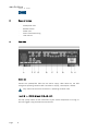
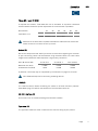
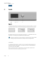
Series 5 soulution nature of sound 520 Preamplifier User manual Preamplifier User manual 520 Dear client We are proud that you decided yourself for a soulution product. You have acquired a preamplifier with outstanding sonic performance which you will enjoy for many years. We understand your eagerness to get started but even though please study this manual step by step before you integrate the preamplifier 520 in your High Fidelity system. This manual contains also useful tips for the optimisation of your overall HiFi-system. If there are any questions regarding the start-up or operation of your preamplifier please do not hesitate to contact your dealer. Have fun! Your soulution team Page 1 soulution nature of sound CE-Declaration of Conformity Spemot AG declares that this product is in conformance with the following directives and standards: Low Voltage Directive 2006/95/EG (EN/IEC 60065:2002) Electromagnetic Compatibility 2004/108/EG (EN 55013:2001, EN 55020:2002, EN 61000-3-2:2006, EN61000-3-3:1995) FCC-Notice Note: This equipment has been tested and found to comply with the limits for a Class B digital device, pursuant to Part 15 of the FCC Rules. These limits are designed to provide reasonable protection against harmful interference in a residential installation. This equipment generates, uses and can radiate radio frequency energy and, if not installed and used in accordance with the instructions, may cause harmful interference to radio communications. However there is no guarantee that interference will not occur in a particular installation. If this equipment does cause harmful interference to radio or television reception, which can be determined by turning the equipment off and on, the user is encouraged to try to correct the interference by one or more of the following measures: - adjust or relocate the receiving antenna increase the separation between the equipment and the receiver connect the equipment into a mains outlet on a circuit different from that to which the receiver is connected consult the dealer or an experienced radio/TV technician for help - Disposal According to the Directive 2002/96/EG of the European Parliament used consumer-electro technical appliances have to be disposed separately and have to be indicated with the following symbol. In the case of disposal of this component please do so in conformity with legal and environmental regulations. Page 2 Preamplifier User manual 520 Table of contents 1 2 3 4 5 6 7 8 9 10 11 12 13 Technical Highlights ............................................................................ 4 Safety advice: ................................................................................. 5 Scope of delivery ................................................................................. 6 Rear side ............................................................................................ 6 Front side ........................................................................................... 8 Remote control ................................................................................. 10 Program-Mode .................................................................................. 11 Trouble shooting ............................................................................... 14 Service ............................................................................................. 14 Safety functions ................................................................................ 15 Warranty ........................................................................................... 15 Specification .................................................................................... 16 Dimensions ....................................................................................... 17 Quick-start Unpacking Unpack your preamplifier 520 Keep the packing for future transportations Treat the top class surface with care Positioning Cooling air must be able to escape unrestricted. Cabling Position the preamplifier 520 on a stable base. Disconnect all appliances of your system from the mains Connect the 520 with your amplifier Connect the 520 with your source components Connect all appliances of your system with the mains While changing cables the 520 must remain disconnect from the mains. Programming Switch-on Default values for all functions are programmed. No additional programming is required for the start-up. Switch-on the 520 preamplifier Select a moderate volume level Switch-on your source components and your amplifier Check the cabling before switch-on Page 3 soulution nature of sound 1 Technical Highlights Layout The audio section is physically separated from the digital circuits. For minimal interferences they are additionally shielded. Power supply The preamplifier 520 has separate power supply units for the audio section as well as for its digital section. A multi-stage filter network reduces potential interferences to a minimum. Volume control Relays switched high precision metal foil resistors form an 80 steps (1 dB) volume control. Each channel has its own volume control resistor network. The volume control allows also adjusting the balance. Depending on the balance setting the volume of the left or right channel is decreased. In order to avoid unpleasant click-noise and harmful voltage peaks while changing the volume the preamplifier 520 disposes over an additional volume control path only active while actually changing the volume. This parallel volume control is realised with a Programmable Gain Amplifier (PGA) which is able to adjust the volume without any noise. As soon as the new volume level is set, the signal path is switched back to the high end resistor network. Output stage The output stage is optimised for velocity, precision and impulse current rating. Thanks to its low output impedance of 10 the output stage is stable on every load (also long cables are driven without problems). Page 4 Preamplifier User manual 2 520 Safety advice: User manual Follow the safety advices Keep this user manual. Mains supply Exclusively use 3 phase power cords with ground conductor. Unplug the 520 from the mains in the following cases: before you manipulate with cables before cleaning during thunder storms before you leave for longer periods Cabling While manipulating with cables the 520 has to remain disconnected from the mains. Wrong cabling may cause damages to your 520, amplifier and loudspeakers. Excessive volumes due to inappropriate handling may cause hearing damages. Transport Use only with the cart, stand, tripod, bracket or table specified by the manufacturer or sold with the apparatus. When a cart is used, use caution when moving cart/apparatus combination to avoid injury or tip over. Packing In order to omit condensation of water inside your preamplifier 520, let it warm up within the packing. Please keep the original packing for future transports. Operation Never run your preamplifier 520 with opened housing with closed cooling-slots with high ambient temperatures (>40°C) close to heat sources like radiators, etc. with extremely high humidity for example in humid cellars close to water (Sink, bathtub, or similar equipment) Cleaning Use a soft and dry towel. We suggest using a non abrasive micro fibre towel. Please do not use any solvents or liquidities Service Service by a qualified person required if the mains-cable or the mains connectors are damaged foreign substances or liquidity have entered the 520 the 520 has seen rain the 520 seems to malfunction the 520 has fallen to the floor or the housing is damaged Page 5 soulution nature of sound 3 Scope of delivery - 4 Preamplifier 520 Remote control Power cord Phono-Termination-Plug User manual Rear side I A Mains (A) Connect the preamplifier 520 with the mains supply. After switch-on, the 520 changes to operating condition OFF (red LEDs in display, consumption <0.5W). Only switch-off the mains connection in operating condition OFF. Input IN 1...IN2 (B) & Input IN 3...IN 4 (C) Use top quality cables for the connection to your source components. For long cables we suggest using the balanced connections. Page 6 Preamplifier User manual 520 Phono MC- Input IN 5 (D) If required the subsonic filter RIAA-IEC can be activated. A dip-switch controlled resistor network allows for optimal adjustment of the termination impedance. Micro-Switch Impedance in 1000 S1 S2 S3 S4 S5 S6 20 100 215 300 405 500 Dipswitch position 1 = connected, 0 = open Detailed list of termination impedance available at www.soulution-audio.com Never connect a line source to the input IN 5. Output (E) Due to the exceptional load stability there are no restrictions regarding the selection of your connecting cables. We recommend using balanced cables. For short cable lengths also unbalanced cables represent a high quality connection. Gain (@ Volume 80) Balanced-Out (XLR) Unbalanced-Out (RCA) IN 1 & IN 2 IN 3 & IN 4 IN 5 (Phono) +10dB +4dB +16dB +10dB +70dB +64dB A potential a hum-loop may be suppressed by the Ground-Lift (page 12) function. Omit feedback-loops while connecting recording devices. LINK (F) The LINK-connection allows controlling the switch-on of other soulution products. Start-Mode (page 12) defines the behaviour of the 520 after switch-on. RS 232 Interface (G) All functions can be controlled through the RS 232 interface. Type label (H) The type label shows the serial number and the nominal rating of your product. Page 7 soulution nature of sound 5 Front side Power (I) The Power button defines the operating condition ON or OFF (red LEDs). In operating condition OFF the audio circuits are completely disconnected from the outputs. Operating condition OFF Start-up Normal operation We suggest switching off the 520 (power consumption in < 0.5W) while not listening to music. It can easily be activated with the remote control. Unplug your 520 from the mains before you manipulate with cables, before cleaning, during thunder storms or before you leave for longer periods. LINK-System: The preamplifier 520 remains in MUTE until all connected LINK-components are switched on (Display LINK Connect). If an error occurs within a LINK-component the display shows LINK ERROR. When the preamplifier 520 is switched off all connected LINK components are switched off simultaneously (operating condition OFF). Page 8 Preamplifier User manual 520 Mute (J) In case of an emergency the safety function Mute allows disconnecting all inputs from the outputs (wrong cabling, feedback loops, etc.). Prog (K) Several Program-Functions allow adjusting the 520 to your individual requirements. The Prog-button switches the 520 to Programming-Mode. Volume (L) The Volume knob controls the functions Volume +/-, Input-Select and is used for the Programming. Volume +/The 520 has a volume control range of 79 dB. We suggest limiting the maximal volume level. Volume-Dim A short push (de)activates the Volume-Dim function (Display for example „D 20“). As long as the Volume-Dim function is active the volume can not be altered. Change to Input-Select Mode Input-Select The new input can be selected and will be activated after timeout of approx. 3 sec. Display / IR-receiver (M) The display shows all relevant information of your preamplifier 520. Page 9 soulution nature of sound 6 Remote control Taste (1) Pre-Modus IR-transmitter Operation until 5m distance and angel of ±45°. (2,3) Volume +/- (4) Volume-Dim Play/Pause (5/6) Select +/- Next / Previous track (7) Enter Function for Program-Mode (8) P (De)activates Program-Mode DIM / (9) Mute (10) ON / OFF (11) - Open/Close (12) PRE - Activates PRE-Mode (13) CD Activates CD-Mode - Change of Remote Ctrl ID: Press the respective buttons for approx. 5 seconds. ID 1: (6), (5), (10) ID 2: (6), (5), (9) Exchange of batteries (2 x AAA): Open the battery tray on the rear side. Insert the batteries into the tray as indicated. Ensure correct polarity of the batteries. Close the tray with corresponding screw. Dispose the exhausted batteries Page 10 CD-Modus - Preamplifier User manual 7 520 Program-Mode General The preamplifier 520 can be adjusted to your individual setup. It is already programmed with default settings. Further programming is not mandatory. We recommend to adjust the Start-Volume and to set the Max-Volume. Function Push on the Prog button switches the preamplifier 520 between operating-mode and programming-mode. Timeout after 10 seconds. Rotating of the Select knob allows selecting the desired Program-Function Push on the Select knob for approval of the selected function. Now the value domain of the selected Program-Function is active. (red LEDs in display). Rotating of the Select knob allows for adjusting the desired value. Push on the Select knob for approval of the respective value. Page 11 soulution nature of sound 7.1 Program-Functions Function Page 12 Values Remarks IN 1, IN 2, IN 3, IN 4, IN 5 Defines which input shall be active after start-up. 1..30..50 Defines the Start-Volume level. In the value domain it changes to the Start-Volume level. 1..30..50 Defines the Dim-Volume level. In the value domain it changes to the Dim-Volume level. 50...80 The maximal volume can be limited. Especially for high efficiency loudspeakers this function should be activated. In the value domain the volume level does not change. <- 9...0...9 -> Balance defines the level difference between left and right channel. OFF, AUX, CD, DAC, DVD, PHON, SACD, TUNE, etc. The inputs IN 1…IN 5 can be renamed individually. ON, OFF Phono-High-Pass (de)activates the subsonic filter (RIAA-norm). OFF should be used only for top quality LP’s and decoupled turntables. Preamplifier User manual Function Values Remarks OFF, IN 1, In 2, IN3, IN 4, The volume and balance settings of the preamp do not have any influence in the Surround-IN. 20..50..80 Defines the output level for the SurroundIN. The setting is ignored if Surround-IN is set to OFF. OFF = connected ON = disconn. (Dis)connects the ground of the balanced outputs. 1 = low 2 = medium 3 = high The intensity of the display can be adjusted in three steps. 1, 2 Defines the identification of the 520. The identification of the remote control has to be defined accordingly 520 Activates the default values (bold) for all functions. Page 13 soulution nature of sound 8 Trouble shooting Error Action No display Check the cabling to the mains supply. Eventually replace the fuse. No music Check - the cabling to the source components and the amplifier. - if proper input has been selected - if the source component is in MUTE - if the amplifier is switched on POWER FAIL In case of a short circuit in the power supply the unit switches off automatically. The display shows POWERFAIL. OVERCURRENT If the current at the output is higher than 0.2 A the MUTE function is activated and the display shows OVERCURRENT. If you cannot identify the error please disconnect the preamplifier 520 from the mains supply and contact your soulution dealer. 9 Service If your soulution product needs service please contact your soulution dealer. For further information see www.soulution-audio.com Page 14 Preamplifier User manual 10 11 520 Safety functions Overcurrent For currents > 0.2 Ampere at the output the preamplifier 520 shuts down automatically. Power supply The power supply is monitored for correct operation. In case of an error the 520 gets shut down automatically. Fuse Model 220-240 V Model 100-120 V 2A/T 250V micro fuse 5x20mm 4A/T 250V micro fuse 5x20mm Warranty All soulution products are guaranteed against defects in material and workmanship for five years from date of purchase. The guarantee is void if the product has been subject to misuse or negligence or has been modified, repaired or opened by a non authorised person without written authorisation of Spemot AG. For the return transport to our premises please use exclusively the original packaging. Transport damages are not subject to this guarantee, repairs will be charged. We recommend effecting transport insurance. If you do not posses the original packaging no more please contact your soulution dealer. Basic repairs may be completed by your soulution dealer. Please clarify whether he is able to do the work before you send the product back to us. Page 15 soulution nature of sound 12 Specification Specification General Nominal Voltage Power consumption Input Impedance Output Gain Frequency response THD+N Signal-to-Noise Ratio Crosstalk Output impedance LINK-Out Dimensions Dimensions Weight Data Model 100-120V Model 220-240V ON Standby 100 - 120 V, 50-60 Hz 220-240 V, 50-60 Hz 150 W <0.5 W (IN 1...IN 5) balanced (IN 1...IN 2) unbalanced (IN 3...IN 4) Phono (IN 5) 10 k 47 k adjustable RCA-In RCA-In XLR-In XLR-In XLR-Out RCA-Out XLR-Out RCA-Out -63...+16 dB -69...+10dB -69...+10dB -75...+4dB DC-500kHz <0.001% >120dB <-120dB 10 12V 442x448x143 mm ca. 20 kg Technical specifications are subject to change without prior notification. Page 16 Preamplifier User manual 13 520 Dimensions Page 17 Spemot AG Industriestrasse 70 CH-4657 Dulliken www.soulution-audio.com [email protected] soulution nature of sound part.no. 92147