1
DIGITAL VODEOCASSETTE RECORDER
MSW-A2000/A2000P
INSTALLATION MANUAL
1st Edition
Serial No. 10001 and Higher: MSW-A2000
Serial No. 40001 and Higher: MSW-A2000P
! WARNING
This manual is intended for qualified service personnel only.
To reduce the risk of electric shock, fire or injury, do not perform any servicing other than that
contained in the operating instructions unless you are qualified to do so. Refer all servicing to
qualified service personnel.
! WARNUNG
Die Anleitung ist nur für qualifiziertes Fachpersonal bestimmt.
Alle Wartungsarbeiten dürfen nur von qualifiziertem Fachpersonal ausgeführt werden. Um die
Gefahr eines elektrischen Schlages, Feuergefahr und Verletzungen zu vermeiden, sind bei
Wartungsarbeiten strikt die Angaben in der Anleitung zu befolgen. Andere als die angegeben
Wartungsarbeiten dürfen nur von Personen ausgeführt werden, die eine spezielle Befähigung
dazu besitzen.
! AVERTISSEMENT
Ce manual est destiné uniquement aux personnes compétentes en charge de l’entretien. Afin
de réduire les risques de décharge électrique, d’incendie ou de blessure n’effectuer que les
réparations indiquées dans le mode d’emploi à moins d’être qualifié pour en effectuer d’autres.
Pour toute réparation faire appel à une personne compétente uniquement.
Attention-when the product is installed in Rack:
1. Prevention against overloading of branch circuit
When this product is installed in a rack and is
supplied power from an outlet on the rack, please
make sure that the rack does not overload the supply
circuit.
2. Providing protective earth
When this product is installed in a rack and is
supplied power from an outlet on the rack, please
confirm that the outlet is provided with a suitable
protective earth connection.
3. Internal air ambient temperature of the rack
When this product is installed in a rack, please make
sure that the internal air ambient temperature of the
rack is within the specified limit of this product.
4. Prevention against achieving hazardous
condition due to uneven mechanical loading
When this product is installed in a rack, please make
sure that the rack does not achieve hazardous
condition due to uneven mechanical loading.
MSW-A2000
MSW-A2000P
Voor de klanten in Nederland
CAUTION
Danger of explosion if battery is incorrectly
replaced.
Replace only with the same or equivalent type
recommended by the manufacturer.
Dispose of used batteries according to the
manufacturer’s instructions.
Dit apparaat bevat een (CF)n-Li batterij voor memory
back-up.
Raadpleeg uw leverancier over de verwijdering van de
batterij op het moment dat u het apparaat bij einde
levensduur afdankt.
Gooi de batterij niet weg. maar lever hem in als KCA.
Vorsicht!
Explosionsgefahr bei unsachgemäßem
Austausch der Batterie.
Bij dit produkt zijn batterijen geleverd.
Wanneer deze leeg zijn, moet u ze niet
weggooien maar inleveren als KCA.
Ersatz nur durch denselben oder einen vom
Hersteller empfohlenen ähnlichen Typ.
Entsorgung gebrauchter Batterien nach Angaben
des Herstellers.
ATTENTION
Il y a danger d’explosion s’il y a remplacement
incorrect de la batterie.
Remplacer uniquement avec une batterie du
même type ou d’un type équivalent recommandé
par le constructeur.
Mettre au rebut les batteries usagées
conformément aux instructions du fabricant.
ADVARSEL!
Lithiumbatteri-Eksplosionsfare ved fejlagtig
håndtering.
Udskiftning må kun ske med batteri
af samme fabrikat og type.
Levér det brugte batteri tilbage til leverandøren.
MSW-A2000
MSW-A2000P
1 (P)
Table of Contents
Manual Structure
Purpose of this manual .............................................................................................. 2
Related manuals ......................................................................................................... 2
1. Installation
1-1.
1-2.
1-3.
1-4.
1-5.
1-6.
1-7.
1-8.
1-9.
1-10.
1-11.
1-12.
1-13.
1-14.
1-15.
1-16.
MSW-A2000
MSW-A2000P
Installation Procedure.................................................................................. 1-1
Supplied Accessories .................................................................................. 1-1
Operating Conditions .................................................................................. 1-2
Power Supply .............................................................................................. 1-2
1-4-1. Voltage and Power Requirements .............................................. 1-2
1-4-2. Power Cord................................................................................. 1-2
Installation Space ........................................................................................ 1-3
Rack Mounting ............................................................................................ 1-4
Matching Connectors and Cables................................................................ 1-9
Signal Inputs and Outputs ......................................................................... 1-10
Switch Settings on Connector Panel ......................................................... 1-14
Analog Audio-related Switch Settings ...................................................... 1-15
Displaying Setup Extended Menu ............................................................. 1-18
Removing/Reattaching Lower Control Panel Unit ................................... 1-19
Switching Search Dial Mode .................................................................... 1-21
Reference System ...................................................................................... 1-22
Settings and Adjustment when External Equipment is Connected ........... 1-23
1-15-1. Settings for Time Code ............................................................ 1-23
1-15-2. VTR Constant Values Settings of Editor ................................. 1-23
1-15-3. System Phase Alignment.......................................................... 1-24
1-15-4. Setup Menu Settings ................................................................ 1-24
Removing/Reattaching Plug-in Boards ..................................................... 1-25
1
Manual Structure
Purpose of this manual
This manual is the installation manual of digital videocassette recorder MSWA2000/A2000P.
This manual is intended for use by trained system and service engineers, and
provides the information that is required to install (environment, connection information, initial setting, etc.) and the setting check sheet.
Related manuals
Besides this “installation manual”, the following manuals are available for digital
videocassette recorder MSW-A2000/A2000P.
. Operation Manual (Supplied with the MSW-A2000/A2000P.)
This manual is necessary for application and operation (and installation) of the MSW.
. Maintenance Manual (Available on request)
Volume-1 : Service Instruction
Volume-2 : Parts List
Volume-3 : Diagrams
These manuals describe the maintenace and service information (service overview, adjustments, board layouts, schematic diagrams, detailed parts list, etc.) for
this unit. If these manuals are required, please contact your local Sony Sales
Office/Service Center.
. Protocol Manual of Remote (9-pin) Connector (Available on request)
This manual explains the protocol for controlling the VTR via the RS-422A (9-pin
serial remote). If this manual is required, please contact your local Sony Sales
Office/Service Center.
. Interface Manual of Parallel I/O (50-pin) Connector (Available on
request)
This manual explains the protocol for controlling the VTR via the parallel (50pin). If this manual is required, please contact your local Sony Sales Office/
Service Center.
. “Semiconductor Pin Assignments” CD-ROM (Available on request)
This “Semiconductor Pin Assignments” CD-ROM allows you to search for
semiconductors used in the MSW.
Semiconductors that cannot be searched for on this CD-ROM are listed in the
maintenance manual (volume-3) for the corresponding unit. The maintenance
manual (volume-3) contains a complete list of all semiconductors and their ID
Nos., and thus should be used together with the CD-ROM.
Part number: 9-968-546-XX
2
MSW-A2000
MSW-A2000P
Section 1
Installation
1-1. Installation Procedure
1-2. Supplied Accessories
Installation procedure of this unit is shown on the following flowchart.
Refer to each section about detail of each flow.
The operation manual is also required to do *-marked
flow.
Screws for rack mounting (PSW 4 x 16) .......................... 4
Operation manual .............................................................. 1
Installation manual ............................................................ 1
Start
Determination of
installation place
1-3. Operating Conditions
1-4. Power Supply
1-5. Installation Space
Unpacking
n
When the unit is transported, it is required to pack the unit into the specified new packing materials.
Do not reuse the packing materials.
Rack mounting
*Connection
*Initial setup
1-6. Rack Mounting
1-7. Matching Connectors and Cables
1-8. Signal Inputs and Outputs
1-9.
1-10.
1-11.
1-12.
1-13.
1-14.
1-15.
Switch Settings on Connector Panel
Analog Audio-related Switch Settings
Displaying Setup Extended Menu
Removing/Reattaching Lower Control Panel Unit
Switching Search Dial Mode
Reference System
Settings and Adjustment when External Equipment is Connected
*Operation check
n
If an error message appears on the time data display area, refer to the operation manual.
(For more details, refer to the maintenance manual volume-1.)
End
MSW-A2000
MSW-A2000P
1-1
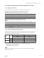
1-3. Operating Conditions
1-4. Power Supply
1-3. Operating Conditions
c
Good air circulation is essential to prevent internal heat
build-up. Place the unit in location with sufficient air
circulation.
Do not block the ventilation holes of the cabinet and the
front and rear panels.
Operating temperature: 5 dC to 40 dC
Operating humidity: 25 % to 80 %
(Condensation not allowed)
Storage temperature: _20 dC to 60 dC
Locations to avoid:
. Areas where the unit will be exposed to direct sunlight
of any other strong lights.
. Areas near heat sources.
. Dusty areas or areas subject to vibration.
. Areas with strong magnetic field.
. Areas with much electrical noise.
. Areas with much static electricity.
. Areas that is impossible to find a specified room for
installation.
(Refer to “1-5. Installation Space” page 1-3.)
. Areas windtight.
Tilt allowance:
Within 30d
Do not slant the front and rear of the
unit more than 30d.
c
Fix the unit securely to avoid drop when the unit is operated at not-horizontal place.
n
AC power supply is required a capacity which is commensurate with rush current.
If the capacity of the AC power supply is not enough, the
breaker of AC power of a supply side may operate or this
unit may not operate normally.
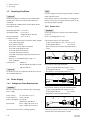
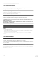
1-4-2. Power Cord
w
Use the specified power cord only when connecting the
AC power.
Never use a damaged power cord.
For customers in the U.S.A. and Canada:
1 Power cord (approx. 2.4 m) ! 1-557-377-11
2 Plug holder (Brown)
3-613-640-01
Please contact your local Sony Sales Office/Service
Center.
1
2
AC inlet
For customers in the United Kingdom:
1 Power cord DK-2401(UK) (approx. 2.4 m)
2 Plug holder (Brown)
3-613-640-01
Plug holder is included in DK-2401(UK).
1
2
AC inlet
1-4. Power Supply
1-4-1. Voltage and Power Requirements
w
Be sure to operate the unit within the range of following
power voltage.
Power voltage:
AC 100 to 240 V ± 10 %
Power frequency:
50 Hz or 60 Hz
Power consumption: 2A (200 W)
(Without the optional kit.)
Rush current:
Power voltage 100 V IN; 10 A
Power voltage 240 V IN; 20 A
This unit’s power line has a switching regulator.
1-2
For customers in Europe except the United Kingdom:
1 Power cord DK-2401(AE) (approx. 2.4 m)
2 Plug holder (Brown)
3-613-640-01
Plug holder is included in DK-2401(AE).
1
2
AC inlet
If the unit is used in the area except above, please contact
your local Sony Sales Office/Service Center.
MSW-A2000
MSW-A2000P
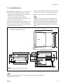
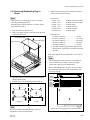
1-5. Installation Space
1-5. Installation Space
Moreover, an air flow that is effective in cooling the unit is
essential. If the ventilation is not enough, the unit may be
damaged because of an increase of the internal temperature.
n
This unit is air-cooled by the five fans. The operation with
the upper lid is removed affects the air cooling by the fans.
Complete the work in a short time as possible when operating the unit for inspection with the upper lid removed. If it
takes a long time, blow to the unit by an electric fan to cool
the unit.
When installing, the installation space must be secured in
consideration of the ventilation and service operation.
. Do not block the ventilation slots at the left side and
right side panels, and vents of the fans.
. Leave a space around the unit for ventilation.
. Leave more than 40 centimeters of space in the rear of
the unit to secure the operation area.
When the unit is installed on the desk or the like, leave at
least four centimeters of space in the left and right sides.
Leaving 40 centimeters or more of space above the unit is
recommended for service operation.
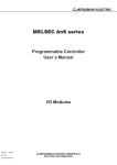
544
416(Rail-installed width)
427(Unit width)
Mass of MSW-A2000/A2000P : 22 kg
45.5
533
577(Maximum traveling distance)
105
481
465
45
454
87
31
87
112
19.5
37
174
87
37
31
15.9
31.5
364
427
34
12.7
123.8
263.5
48
415.9
457.5
n Remove the feet when rack mounting.
(38.5)
Unit : mm
Dimensions when Rack-Mounting
n
The MSW-A2000/A2000P allows the operation with the detached lower control panel unit.
For details, refer to Section 1-12.
MSW-A2000
MSW-A2000P
1-3
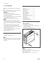
1-6. Rack Mounting
1-6. Rack Mounting
Parts Packed in RMM-130
Explains how to mount this unit into a 19-inch standard
rack.
Be sure to mount this unit into a rack accurately following
the procedure and notes mentioned below.
c
. Use the specified rack mount rail.
The use of other rail of low strength may drop the unit
and cause the risk of injury.
. To prevent toppling over the rack, fix it on the horizontal
and firm floor securely with bolts, etc.
. Mount the unit into a rack with a steady posture.
m
. When other equipment with built-in hard disk drive is
already mounted in the same rack for mounting this unit,
turn off the power of the equipment before mounting this
unit.
. Connect long enough cables on the connector panel,
considering that the unit is pulled out from the rack.
. Do not operate this unit without the upper lid and bottom
plate except when servicing it.
. Adjust the temperature inside the rack within the range
of the unit’s operating temperature.
(Refer to Section 1-3.)
.
.
.
.
.
.
.
.
.
.
.
.
Slide rails ......................................... 2
Rack angles (handles) ..................... 2
Rail brackets .................................... 4
Plate nuts (large) ............................. 4
Plate nuts (small) ............................. 4
Screws (PSW4 x 16) ...................... 4
Screws (B4 x 8) .............................. 8
Hexagon socket head cap screws .... 8
Flat washers ..................................... 8
Screws (RK5 x 14) ......................... 2
Ornamental washers ........................ 2
L-shaped hexagon wrench .............. 1
Rack Mounting Procedure
. Removing the feet
1. Set the unit its side panel down.
2. Unscrew the four screws to remove the feet from the
bottom plate of the unit.
3. Set the unit in a horizontal position.
Foot
Specified Rack Mount Kit
RMM-130 (Optional accessory)
PS4 x 20
n
When mounting this unit into Sony LMS (Library Management System) VTR console, it is necessary to modify the
VTR console.
Foot
PS4 x 20
n
Keep these screws and the feet.
When operating the unit after demounting it from the rack,
be sure to reattach the feet.
Tightening torque: 98 x 10_2 N . m {10 kgf . cm}
1-4
MSW-A2000
MSW-A2000P
1-6. Rack Mounting
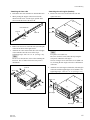
. Attaching the inner rails
4. Pull out the inner rails from the two intermediate rails.
5. While pressing the stopper of the inner rail in the
direction of the arrow A in the figure, pull the inner
rail out in the direction of the arrow B.
Intermediate rail
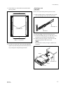
. Attaching the rack angles (handles)
8. Remove the four screws from both sides (left and
right) of the unit.
B4 x 6
Inner rail
Outer rail
B4 x 6
A
Stopper
B
B4 x 6
6. Remove the ten screws from both sides (left and right)
of the unit as shown in the figure below.
7. Attach the two inner rails to both sides (left and right)
of unit with the removed screws in the step 6.
Tightening torque: 120 x 10_2 N . m {12.2 kgf . cm}
n
Be sure to use the (B4 x 6) screws when attaching the
inner rail. The use other-sized screws may cause a
malfunction.
Inner rail
B4 x 6
B4 x 6
n
Keep these screws (B4 x 6).
Be sure to use these screws when directly fixing the
side panels without the rack angles.
The use of longer screws such as the screws (PSW 4 x
16) for fixing the rack angles will cause a malfunction
of the unit.
9. Attach the two rack angles to both sides (left and right)
of the unit with the supplied four screws (PSW4 x 16).
Tightening torque: 120 x 10_2 N . m {12.2 kgf . cm}
PSW4 x 16
B4 x 6
PSW
4 x 16
Inner rail
Rack angle
PSW4 x 16
Rack angle
MSW-A2000
MSW-A2000P
PSW4 x 16
1-5
1-6. Rack Mounting
. Loosely attaching the rail brackets
10. Slide the intermediate rail as shown in the figure, and
then loosely attach the rail bracket to the outer rail
with a plate nut (large) and the two screws.
. Attaching the outer rails
12. Loosely attach the two outer rails to the middle of the
4U space in the rack for mounting this unit, with the
eight hexagon socket head cap screws, eight flat
washers, and four plate nuts (small).
Plate nut (small)
Plate nut (large)
Rail bracket
Outer rail
B4 x 8
Intermediate rail
Rail
Rail bracket
Flat washer
By 4U
Hexagon socket
head cap screw
2U
L-shaped hexagon wrench
11. Slide the ball retainer in the direction of the arrow, and
then loosely attach the rail bracket to the outer rail
with a plate nut (large) and the two screws.
Outer rail
Plate nut (large)
Rail bracket
Intermediate rail
Ball retainer
13. As shown in the following figure, adjust each frontside position of the outer rails on both sides (left and
right) so that the distance from the surface of the rack
to the tip of the rail becomes within the range of 50 to
55 millimeters.
14. Fully tighten the eight screws (B4 x 8) fixing the four
rail brackets.
Tightening torque: 120 x 10_2 N . m {12.2 kgf . cm}
Rack
B4 x 8
Outer rail
Rail bracket
50 to 55 mm
Rack angle
1-6
B4 x 8
MSW-A2000
MSW-A2000P
1-6. Rack Mounting
15. Check that the two intermediate rails attached to the
rack are parallel.
. Mounting in rack
c
Be sure to carry the unit by the two persons or more.
A
17. Slide each ball retainer of intermediate rails on both
sides (left and right) in the direction of the arrow.
Intermediate rail
Intermediate rails
Ball retainer
A'
Width : A = A' = 416 mm
16. To fix the two outer rails to the rack, fully tighten the
eight loosely fitted hexagon socket head cap screws in
step 12 using the L-shaped hexagon wrench.
18. Pull equal length of each rail on both sides out.
19. Lift the unit holding the gripes on both sides, slowly
insert the inner rails into the intermediate rails.
20. While pressing each stopper of inner rails on both
sides, slowly push the unit into the rack.
n
Be careful not to catch your finger or hand in rack
mount rail.
Stopper
Intermediate rail
Stopper
Inner rail
MSW-A2000
MSW-A2000P
1-7
1-6. Rack Mounting
21. Slide the unit in and out from the rack about three
times and check that the slide rails move smoothly.
If they are not smoothly, demount the unit and go back
to “Attaching the outer rails” (step 12).
c
When demounting the unit, carry it by the two persons
or more.
n
This unit does not have the feet at this operating.
Put down the unit on the floor or other, being careful
not to damage the unit.
22. Secure the unit to the rack with the two screws and
two ornamental washers.
Tightening torque: 120 x 10_2 N . m {12.2 kgf . cm}
Ornamental washer
RK5 x 14
RK5 x 14
Ornamental washer
1-8
MSW-A2000
MSW-A2000P
1-7. Matching Connectors and Cables
1-7. Matching Connectors and Cables
When external cables are connected to the connector of this unit, the hardware listed below (or equivalents) must be used.
Panel indication
Matching connector (cable)
Sony part No.
AUDIO INPUT
XLR 3P, MALE
1-508-084-00
AUDIO OUTPUT
XLR 3P, FEMALE
1-508-083-00
MONITOR OUTPUT
XLR 3P, FEMALE
1-508-083-00
TIME CODE IN
XLR 3P, MALE
1-508-084-00
XLR 3P, FEMALE
1-508-083-00
VIDEO INPUT
BNC 75Z, MALE
1-569-370-12
VIDEO OUTPUT
BNC 75Z, MALE
OUT
AUDIO INPUT (AES/EBU)
1-569-370-12
BNC 75Z, MALE
*1
*1
AUDIO OUTPUT (AES/EBU)
BNC 75Z, MALE
REMOTE 2
PARALLEL I/O (50P)
D-SUB 50P, MALE and
JUNCTION SHELL 50P
REMOTE 1-IN (9P)
9P remote control cable
(RCC-G series)
or
D-SUB 9P, MALE and
JUNCTION SHEEL 9P
REMOTE 1-OUT (9P)
1-569-370-12
1-569-370-12
1-565-516-11
1-563-379-11
_
1-560-651-00
1-561-749-00
9P remote control cable
(RCC-G series)
or
D-SUB 9P, MALE and
JUNCTION SHEEL 9P
1-560-651-00
1-561-749-00
RS-232C
D-SUB 9P, FEMALE
1-563-815-21
CONTROL PANEL
10P, MALE (connecting cable)
1-792-418-11
VIDEO CONTROL
D-SUB 15P, FEMALE and
JUNCTION SHELL 15P
1-561-610-21
1-561-929-00
(OPTION)
Specified by optional kit
or
D-SUB 9P, MALE and
JUNCTION SHEEL 9P
_
1-560-651-00
1-561-749-00
BNC 75Z, MALE *2
1-569-370-12
BNC 75Z, MALE *2
1-569-370-12
JM-60 stereo phone plug
_
SDI
SDTI
PHONE
*3
Remarks
_
*1: Coaxial cable length : max. 600 meters (Reference value based on MSW series)
It is recommended to connect the BELDEN8281 cable or equivalent to this connector.
*2: Coaxial cable length : max. 200 meters (Reference value based on MSW series)
It is recommended to connect the BELDEN8281 cable or equivalent to this connector.
*3: It is used on the front (upper control panel).
MSW-A2000
MSW-A2000P
1-9
1-8. Signal Inputs and Outputs
1-8. Signal Inputs and Outputs
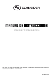
Reduced drawing of rear panel
3
1
2
5
4
Input connectors
1 AUDIO INPUT
XLR 3-pin x 4 (1 set : CH1, CH2, CH3, and CH4)
Analog audio 4 channels
LOW OFF : _60 dBu, high impedance, balanced
HIGH OFF : +4 dBu (Standard), high impedance, balanced
HIGH ON : +4 dBm (Standard), 600 Z termination, balanced
1 TIME CODE IN
XLR 3-pin x 1
Time code 0.5 to 18 V p-p, 10 kZ, balanced
2 VIDEO INPUT, REF.VIDEO
BNC x 2 in loop through connection
Outside reference video signal (Black burst or composite sync)
0.3 V p-p, 75 Z, sync negative
2 VIDEO INPUT, COMPOSITE
BNC x 2 in loop through connection
Analog composite video 1.0 V p-p, 75 Z, sync negative
2 VIDEO INPUT, COMPONENT
BNC x 3 (1 set : Y, R-Y, and B-Y)
Analog component video
Y
: 1.0 V p-p, 75 Z, sync negative
R-Y/B-Y : 0.7 V p-p, 75 Z
3 AUDIO INPUT (AES/EBU)
BNC x 4 (1 set : CH1/2, CH3/4, CH5/6, and CH7/8)
Digital audio 8 channels
AES/EBU format, 2 channel mode, 1.0 V p-p, 75 Z
5 SDI INPUT
BNC x 1 (active through out x 1)
Serial digital interface (270 Mbit/s) in conformity to SMPTE 259M & ITU-R BT.656
5 SDTI INPUT
BNC x 1
Serial data transport interface (270 Mbit/s) in conformity to
SMPTE 305M (SDTI) and
SMPTE 322M (SDTI-CP)
Remote connectors
4 REMOTE 2 PARALLEL I/O (50P)
D-SUB 50P connector (Refer to Optional “Interface manual” for details.)
4 REMOTE1-IN (9P)
D-SUB 9P connector (RS-422A interface)
Remote control
4 REMOTE1-OUT (9P)
D-SUB 9P connector (RS-422A interface)
Remote control
4 RS-232C
D-SUB 9P connector (RS-232C interface)
for ISR (Interactive Status Reporting)
4 CONTROL PANEL
10P connector
for an outside control panel connection only
4 VIDEO CONTROL
D-SUB 15P connector
for a TBC remote controller (BVR-50) connection
4 (OPTION)
D-SUB 9P connector
for an optional kit
1-10
MSW-A2000
MSW-A2000P
1-8. Signal Inputs and Outputs
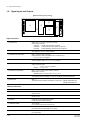
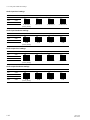
Rear panel
LOW
HIGH
ON
600Z
OFF
R
VIDEO INPUT
AUDIO INPUT
CH2 LEVEL
CH3 LEVEL
CH1 LEVEL
LOW
HIGH
ON
600Z
OFF
L
LOW
OFF
R
CH4 LEVEL
HIGH
ON
600Z
LOW
OFF
REF.VIDEO
HIGH
ON
600Z
OFF
CONPOSITE
ON OFF
CONPONENT
CH2
AUDIO OUTPUT
CH3
AUDIO INPUT (AES/EBU)
CH3/4
CH5/6
CH7/8
SDI
INPUT
75Z Y
75Z
L
R-Y
CH1
CH1/2
ON
CH1/2
AUDIO OUTPUT (AES/EBU)
CH3/4
CH5/6
CH7/8
B-Y
CH4
REMOTE 2 PARALLEL I/O(50P)
VIDEO OUTPUT
R
MONITOR OUTPUT
L
IN
TIME CODE
OUT
CONPOSITE
CONPONENT
1
Y
2
R-Y
REMOTE 1-IN(9P)
CONTROL PANEL
SDI
OUTPUT
SDTI
INPUT
1
AC IN
3
(SUPER)
REMOTE 1-OUT(9P)
VIDEO CONTROL
2
OUTPUT
1
3 (SUPER)
2
B-Y
RS232C
(OPTION)
Output connectors
1 AUDIO OUTPUT
XLR 3-pin x 4 (1 set : CH1, CH2, CH3, and CH4)
Analog audio 4 channels
+4 dBm (Standard) (600 Z load), low impedance, balanced
1 TIME CODE OUT
XLR 3-pin x 1
Time code 2.2 V p-p, low impedance, balanced
1 MONITOR OUTPUT
XLR 3-pin x 2 (1 set : R and L)
Analog audio
+4 dBm (Standard) (600 Z load), low impedance, balanced
2 VIDEO OUTPUT, COMPOSITE
BNC x 3 (including 1 for character superimpose)
Analog composite video 1.0 V p-p, 75 Z, sync negative
2 VIDEO OUTPUT, COMPONENT
BNC x 3 (1 set : Y, R-Y, and B-Y)
Analog component video
Y
: 1.0 V p-p, 75 Z, sync negative
R-Y/B-Y : 0.7 V p-p, 75 Z
3 AUDIO OUTPUT (AES/EBU)
BNC x 4 (1 set : CH1/2, CH3/4, CH5/6, and CH7/8)
Digital audio 8 channels
AES/EBU format, 2 channel mode, 1.0 V p-p, 75 Z
5 SDI OUTPUT
BNC x 3 (including 1 for character superimpose)
Serial digital interface (270 Mbit/s) in conformity to SMPTE 259M & ITU-R BT.656
5 SDTI OUTPUT
BNC x 2
Serial data transport interface (270 Mbit/s) in conformity to
PHONE
(Upper control panel)
MSW-A2000
MSW-A2000P
SMPTE 305M (SDTI) and
SMPTE 322M (SDTI-CP)
JM-60 stereo phone jack
Analog audio
up to _12 dBu (8 Z load), unbalanced
1-11
1-8. Signal Inputs and Outputs
REMOTE 2 PARALLEL I/O: 50-pin (female)
External view
17
1
33
18
50
34
Pin No.
I/O *1
Setting change *2 Signal
Description
1
IN
O
FF
CLOSURE SW (FF)
2
OUT
X
REC SW
PANEL REC SW OUT
3
OUT
X
PLAY SW
PANEL PLAY SW OUT
4
OUT
X
STOP SW
PANEL STOP SW OUT
5
OUT
X
ENTRY SW
PANEL ENTRY SW OUT
6
OUT
X
REF SYSTEM ALARM
Non-REFERENCE
7
OUT
X
CF LOCK
COLOR FRAME LOCK STATUS
8
OUT
X
DRUM LOCK
LOCK STATUS OF DRUM SERVO
9
OUT
X
CAP LOCK
LOCK STATUS OF CAPSTAN SERVO
10
OUT
O
CUE PRESET
EDIT PRESET STATUS of the CUE Channel
11
OUT
O
TC PRESET
EDIT PRESET STATUS of the TC Channel
12
OUT
O
OXIDE/METAL
OXIDE/METAL TAPE STATUS
13
OUT
O
TAPE THICKNESS
TAPE THICKNESS STATUS
14
OUT
X
SPARE
SPARE
15
OUT
X
SPARE
SPARE
16
——
——
+12V
——
17
——
——
GND
SIGNAL GND
18
IN
O
PREROLL
CLOSURE SW (PREROLL)
19
IN
O
STBY ON
CLOSURE SW (STANDBY ON)
20
IN
O
REW
CLOSURE SW (REW)
21
IN
O
ENTRY
CLOSURE SW (ENTRY IN)
22
IN
O
STBY OFF
CLOSURE SW (STANDBY OFF)
23
IN
O
EJECT
CLOSURE SW (EJECT)
24
OUT
X
REC
REC STATUS
25
OUT
X
CH CONDITION RED
CHANNEL CONDITION RED STATUS
26
OUT
O
ASSEMBLE PRESET
ASSEMBLE PRESET STATUS
27
OUT
O
EDIT OUT
EDIT STATUS
28
OUT
O
EJECT OUT
EJECT STATUS
29
OUT
O
ANALOG/DIGITAL
ANALOG/DIGITAL STATUS
30
OUT
O
REEL HUB
REEL HUB STATUS
31
OUT
X
REM2 SETTING DATA RESET REMOTE2 SETTING DATA RESET STATUS
32
OUT
X
ALL REC INHIBIT
33
——
——
GND
34
IN
O
PLAY
CLOSURE SW (PLAY)
35
IN
O
STOP
CLOSURE SW (STOP)
ALL REC INHIBIT STATUS
(Continue)
1-12
MSW-A2000
MSW-A2000P
1-8. Signal Inputs and Outputs
(Continued)
Pin No.
I/O * 1
Setting change * 2 Signal
Description
36
IN
O
REC
CLOSURE SW (REC)
37
OUT
X
REV LAMP
REV LAMP STATUS
38
OUT
O
DA2 PRESET
DA2 EDIT PRESET STATUS
39
OUT
O
DA1 PRESET
DA1 EDIT PRESET STATUS
40
OUT
X
FWD LAMP
FWD LAMP STATUS
41
OUT
O
DA4 PRESET
DA4 EDIT PRESET STATUS
42
OUT
O
DA3 PRESET
DA3 EDIT PRESET STATUS
43
OUT
X
STOP
STOP STATUS
44
OUT
O
VIDEO PRESET
VIDEO EDIT PRESET STATUS
45
OUT
O
INSERT PRESET
INSERT EDIT PRESET STATUS
46
OUT
X
STBY ON
STANDBY ON STATUS
47
OUT
X
PLAY
PLAY STATUS
48
OUT
X
REMOTE
REMOTE STATUS
49
OUT
X
ALARM
SYSTEM ALARM STATUS
50
OUT
O
PREROLL
PREROLL STATUS
*1: Input ; 47 kZ pull up to +5 V (close/open)
Output ; 10 kZ pull up to +5 V (0 V or open)
*2: The pins described as O mark are possible to change the setting.
Refer to the optional interface manual for changing the setting.
REMOTE1-IN: 9-pin (female)
REMOTE1-OUT: 9-pin (female)
RS-232C: 9-pin (male)
External view
External view
5
1
1
9
5
6
6
9
Pin No.
Signal
Pin No.
Signal
1
GND
1
DCD ; Data Carrier Detect (Input)
2
RM TX(_)
2
RXD ; Received Data (Input)
3
RM RX(+)
3
TXD ; Transmitted Data (Output)
4
GND
4
DTR ; Data Terminal Ready (Output)
5
PRIORITY
5
SG ; Signal Ground
6
GND
6
DSR ; Data Set Ready (Input)
7
RM TX(+)
7
RTS ; Request to Send (Output)
8
RM RX(_)
8
CTS ; Clear to Send (Input)
9
GND
9
NC
MSW-A2000
MSW-A2000P
1-13
1-8. Signal Inputs and Outputs
1-9. Switch Settings on Connector Panel
CONTROL PANEL: 10-pin (female)
(OPTION): 9-pin (female)
External view
External view
5
1
3
6
9
2
5
8
10
9
Pin No.
Signal
Terminal voltage (V)
Pin No.
Signal
1
+21 V
+21 V
1
GND
2
+21 V
+21 V
2
RM TX (_)
3
KEY TX (+) (Output)
RS422
3
RM RX (+)
4
FRONT/REAR
+5: FRONT
0: REAR
4
GND
5
——
5
KEY TX (_) (Output)
RS422
6
GND
6
KEY RX (+) (Input)
RS422
7
RM TX (+)
7
GND
8
RM RX (_)
8
KEY RX (_) (INPUT)
RS422
9
GND
9
GND
——
10
GND
——
VIDEO CONTROL: 15-pin (male)
When the unit is installed, be sure to perform the following
setup.
Refer to the operation manual “Section 2 Location and
Function of Parts” for setup.
8
9
6
1-9. Switch Settings on Connector Panel
External view
1
1
15
. Analog audio input level/600 Z termination switches
Pin No.
Signal
Terminal voltage (V)
1
SYNC CONT (Input)
_5 to +5
2
HUE CONT (Input)
_5 to +5
3
SC CONT (Input)
_5 to +5
4
VIDEO LEVEL CONT (Input)
_5 to +5
5
SETUP CONT (Input)
_5 to +5
6
CHROMA LEVEL CONT (Input) _5 to +5
7
REG _12V (Output)
_12
8
GND
——
9 to 12
NC
——
13
Y/C DELAY CONT (Input)
_5 to +5
14
NC
——
15
REG +12V (Output)
+12
1-14
. 75 Z termination switch of reference video input
. 75 Z termination switch of composite video input
MSW-A2000
MSW-A2000P
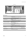
1-10. Analog Audio-related Switch Settings
1-10. Analog Audio-related Switch Settings
If necessary, perform the following audio-related settings using the switches on the APR-52 board.
. Audio input level *1
. Audio input headroom *2
. Audio output level *1
. Audio output headroom *2
. Monitor output level *1
. Monitor output headroom *2
. Monitor output level, fixed/variable selection
*1: Select the level for each channel from +4, 0, _3, _20 dBm. (Factory settings: +4 dBm for each channel)
*2: Select the headroom for each channel from 20, 18, 16 dBm. (Factory settings: 20 dBm for each channel)
A
B
C
D
E
F
G
H
J
K
APR-52
L
N
P
M
A
S401
S901
S1001
S900
S1000
S800
S700
S600
S500
S902
S801
S701
S601
S501
S1002
1
S301
S201
S101
2
3
S400
S300
S200
S100
4
5
6
APR-52 Board (Side A)
n
Refer to Section 1-16 for removing and
reattaching the plug-in boards.
< Top View >
MSW-A2000
MSW-A2000P
1-15
1-10. Analog Audio-related Switch Settings
Audio input level settings
S200
CH3
S300
1
2
3
4
1
2
3
4
1
2
3
4
CH4
S400
+4 dBm/600 Z
(Factory setting)
0 dBm/600 Z
_3 dBm/600 Z
_20 dBm/600 Z
O
N
CH2
O
N
S100
O
N
CH1
O
N
Ref. No.
1
2
3
4
Input level and Switches state (\\ : Knob position)
Channel
Audio input headroom settings
S401
O
N
CH4
1
2
3
4
S301
O
N
CH3
1
2
3
4
S201
O
N
S101
CH2
1
2
3
4
CH1
Input headroom and Switches state (\\ : Knob position)
O
N
Ref. No.
1
2
3
4
Channel
20 dB
(Factory setting)
18 dB
16 dB
12 dB
Audio output level settings
S801
+4 dBm/600 Z
(Factory setting)
0 dBm/600 Z
_3 dBm/600 Z
O
N
CH4
1
2
3
4
S701
O
N
CH3
1
2
3
4
S601
O
N
S501
CH2
1
2
3
4
CH1
Output level and Switches state (\\ : Knob position)
O
N
Ref. No.
1
2
3
4
Channel
_20 dBm/600 Z
Audio output headroom settings
S800
1-16
O
N
CH4
1
2
3
4
S700
O
N
CH3
1
2
3
4
S600
O
N
S500
CH2
1
2
3
4
CH1
Output headroom and Switches state (\\ : Knob position)
O
N
Ref. No.
1
2
3
4
Channel
20 dB
(Factory setting)
18 dB
16 dB
12 dB
MSW-A2000
MSW-A2000P
1-10. Analog Audio-related Switch Settings
Monitor output level settings
O
N
1
2
3
4
O
N
S1002
1
2
3
4
R
O
N
S902
1
2
3
4
L
Output level and Switches state (\\ : Knob position)
O
N
Ref. No.
1
2
3
4
Channel
+4 dBm/600 Z
(Factory setting)
0 dBm/600 Z
_3 dBm/600 Z
_20 dBm/600 Z
Monitor output headroom settings
O
N
O
N
1
2
3
4
S1000
1
2
3
4
R
O
N
S900
1
2
3
4
L
Output headroom and Switches state (\\ : Knob position)
O
N
Ref. No.
1
2
3
4
Channel
20 dB
(Factory setting)
18 dB
16 dB
12 dB
Monitor output level switching (fixed or variable)
When the variable level is selected, the level is adjusted with the PHONE level control knob.
Channel
Ref. No.
L
S901
R
S1001
Setting and Switch state (\\ : Knob position)
Fixed
1
2
O
N
Variable
1
2
O
N
(Factory setting)
MSW-A2000
MSW-A2000P
1-17
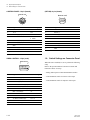
1-11. Displaying Setup Extended Menu
1-11. Displaying Setup Extended Menu
The extended menus of the setup menu are usually not accessible. To display them, set the bit-1 of the
DIP switch S1502 on the SS-89 board to ON.
n
For details on H-, 9- and B-series items, refer to the operation manual supplied with the unit.
For details on F-series items, refer to the maintenance manual, volume-1.
Ref. No. Bit
Name
Description
Factory setting
S1502
EXTENDED MENU
OFF (OPEN) : Not display extended menu of setup menu
ON (CLOSE) : Displays extended menu of setup menu
OFF (OPEN)
1
n
Never change the settings of the switches except above.
A
1
B
C
D
E
F
G
H
J
SS-89
K
L
ON
N
P
M
S101
S1501
2
1
8
S1502
A
3
4
5
6
SS-89 Board (Side A)
n
Refer to Section 1-16 for removing and
reattaching the plug-in boards.
< Top View >
1-18
MSW-A2000
MSW-A2000P
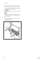
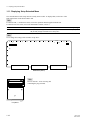
1-12. Removing/Reattaching Lower Control Panel Unit
1-12. Removing/Reattaching Lower
Control Panel Unit
Removal/Extension of the Lower Control Panel
Unit
The lower control panel unit is detachable from the main
unit, therefore operation with placing the single panel unit
on the table as a keyboard of a personal computer is
possible. (The length of the connected cable is about 62
centimeters.)
1. After pressing the release levers, open the lower
control panel as shown in the figure below.
2. Disconnect the cable from the connector on the back
side of the lower control panel unit and from the cord
holder.
3. Remove the two screws shown in the figure.
PANEL SELECT switch
Front switch panel
Release lever
Cable
Release lever
BVTT3 x 6
Lower control panel unit
Back view
Lower control panel unit
Cable
BVTT3 x 6
Not only connecting the cable to a CONTROL PANEL
connector in the front switch panel, but connection between the cable and a CONTROL PANEL connector in the
rear connector panel provides operating the lower control
panel. After connection, set a PANEL SELECT switch on
the switch panel as follows:
Connector to be connected
to lower control panel unit
Setting of PANEL
SELECT switch
Front (on the switch panel)
FRONT side
Rear (on the connector panel)
REAR side
Cable holder
Connector
4. Lightly draw the lower control panel unit toward you,
and then lift it upward.
Settings when connecting the two lower control
units
When connecting the two lower control units to one MSWA2000/A2000P, select which operation to enable by
setting from the setup extended menu ITEM-117.
Operation
enabled
Setting of ITEM-117
Setting of PANEL
SELECT switch
Front-side panel
EXT or PARA
FRONT side
Rear-side panel
EXT
REAR side
Both panels
PARA
REAR side
Lower control panel unit
n
ITEM-117’s factory setting : EXT
MSW-A2000
MSW-A2000P
1-19
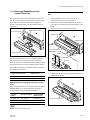
1-12. Removing/Reattaching Lower Control Panel Unit
5. Erect the feet on the back side of the lower control
panel unit and place it.
9. Connect the connecting cable to the connector on the
back side of the lower control panel unit and fix the
connecting cable in the cord holder.
Foot
Back view
Cable
Foot
Connector
Lower control panel unit
Cable holder
6. While lifting the outer stay by the forefinger, fold the
arm in the direction of the arrow shown in the figure.
n
Move the forefinger off before pinching it between the
arm and chassis.
Arm (right side)
n
In the case of connecting between the CONTROL PANEL
connector of the rear connector panel and the lower control
panel unit, set the PANEL SELECT switch on the switch
panel to REAR.
Craw
Reattachment of the Lower Control Panel Unit
Outer stay
7. Check that each arm is locked and unmoving state. If it
rattles, lightly push in the arm until it locks.
8. Take the connecting cable off the three cord holders on
the switch panel.
Reattach the lower control panel unit in the reverse order
of removal and extension, yet when reattaching, use care
about following points.
. Set the PANEL SELECT switch to FRONT.
. When opening the arms, follow step 1.
. When reattaching the lower control panel unit to the
arms, fit each claw of the arms with the notches on the
back side of the lower control panel unit, then press.
. Check the screw holes are visible from your side before
tightening the screws.
Cable holders
Arm (left side)
Cable
Arm (right side)
1-20
MSW-A2000
MSW-A2000P
1-13. Switching Search Dial Mode
1-13. Switching Search Dial Mode
There are two kinds of operation to switch the search dial
on the lower control panel between jog mode and shuttle
mode.
. SHUTTLE/JOG button selecting
To enter the shuttle mode, press the SHUTTLE button.
To enter the jog mode, press the JOG button.
4. Check to see that the shaft of the search dial is not seen
in the round hole of the mode selection plate, and then
tighten the screw.
Back view
Mode selection plate
Screw
. Search dial pressing
When you press the dial, the search dial toggles between
shuttle and jog modes.
It is possible to prohibit a manner of toggling.
Round hole
Prohibiting Search Dial Pressing
1. After pressing the release levers, open the lower
control panel as shown in the figure below.
2. Loosen a screw on the backside of the search dial as
shown in the figure.
n
If it is difficult to loosen the screw, remove the lower
control panel unit in advance.
(Refer to Section 1-12.)
3. Slide the mode selection plate in the direction indicated by the arrow until it contacts the portion A.
Release lever
Release lever
The shaft is not seen.
Allowing Search Dial Pressing
1. Open the lower control panel. (Operation side up)
2. Loosen a screw on the backside of the search dial as
shown in the figure.
3. Fully slide the mode selection plate in the direction
indicated by the arrow.
4. Check to see that the shaft of the search dial is seen in
the round hole of the mode selection plate, and then
tighten the screw.
Back view
Mode selection plate
Screw
Lower control panel unit
Back view
Mode selection plate
Search dial
Screw
Search dial shaft
Round hole
The shaft is seen.
Portion A
MSW-A2000
MSW-A2000P
1-21
1-14. Reference System
1-14. Reference System
For each reference signal in this unit, either of an external reference video signal (*3) or input video
signal (*4) is automatically selected according to the setting of function menu item OUT REF, the setting
of setup menu ITEM-309, and the operation mode (PB/EDIT/REC) of this unit. (Refer to the table below.)
Regarding the reference signal (clock) of an analog video signal in an A/D converter, the analog video
signal itself is used as a reference signal under any setting.
Menu ITEM-309
EXT
OUT REF
—————
Operation mode
—————
AUTO
REF
PB
EDIT (*1)
INPUT
EDIT (*2)
REC
—————
Video input A/D
Video output process
Digital audio
External Reference Video (*3)
Input Video (*4)
Servo system
*1: When the setup menu ITEM-309 is set to “AUTO1”.
*2: When the setup menu ITEM-309 is set to “AUTO2”.
*3: REF. VIDEO input
*4: The input video signal is selected by the video input selection.
m
. To select the video input, open the HOME page on the function screen and use the F1 button (VID. IN).
. To set the OUT REF, open the P4 page (MISCELLANEOUS) on the function screen and use the F2
button (OUTREF).
Audio Signal Independent Recording
Even if an input video signal is selected as the reference signal, the reference signal is automatically
selected to an external reference video signal for the period in which the no input video signal is input.
When no external reference video signal is input, the internal-generated reference signal is automatically
selected for the period.
An audio signal can be independently recorded by this system even if no reference video signal is input
from the outside.
Alarm Display for Video Input Signal and Reference Signal
1. Blink of the selected input video indication area of the video input selection
This area at the HOME page on the function screen blinks when signal is not input to the connector
selected by the video input selection.
2. Blink of the STOP button
The button blinks when the reference signal is not locked to an input video signal.
(This function can be cancelled in the setup menu ITEM-105.)
. When the OUT REF is set to “INPUT”:
The STOP button blinks when the signal is not input to the connector selected by the video input
selection.
. When the OUT REF is set to “REF”:
The STOP button blinks in the following either cases.
When no reference signal is input to REF. VIDEO connector.
When the reference video signal (REF.VIDEO input) is not synchronized with an input video signal
selected by the video input selection.
1-22
MSW-A2000
MSW-A2000P
1-15. Settings and Adjustment when External Equipment is Connected
1-15. Settings and Adjustment when External Equipment is Connected
1-15-1. Settings for Time Code
To set the TIME CODE, open the P1 page (TCG/TCR SETTING) on the function screen.
When Editing with an Editor (BVE-2000, etc.) Capable of the 1st Edit
When MSW-A2000/A2000P is used by connecting to an editor, set as follows.
Button
Item (Display)
Setting
F1
TCG INT/EXT (TCG)
INT
F2
TCG PRESET/REGEN (TCG)
PRESET
F3
TCG RUN (RUN)
FREE
When Editing with Direct Machine-to-Machine (VTR to VTR)
n
The setup menu ITEM-610: REGEN CONTROL MODE setting data must be set to “AS&IN”.
Button
Item (Display)
Setting
F1
TCG INT/EXT (TCG)
INT
F2
TCG PRESET/REGEN (TCG)
PRESET
F3
TCG RUN (RUN)
REC
1-15-2. VTR Constant Values Settings of Editor
Set the VTR constant values according to the table below when the editor which needs the setting of VTR
constant values is connected. Moreover, the change of VTR constant values are required when the 525/
625 system is switched by setup menu of this unit.
Model
MSW-A2000P
VTR CONSTANT 2
Data No.
Data No.
525/625
1
MSW-A2000
VTR CONSTANT 1
525/60
B0
2
61
3
00
4
96
5
07
6
07
7
03
8
1
2
3
4
5
6
7
8
*
0A
07
FB
00
81
3D
FF
5A
*
8A
625/50
B1
61
00
7D
07
07
03
8A
0A
06
FB
00
83
4B
FF
4B
525/60
B0
61
00
96
07
07
03
8A*
0A
07
FB
00
81
3D
FF
5A
625/50
B1
61
00
7D
07
07
03
8A*
0A
06
FB
00
83
4B
FF
4B
*: Set the data of No.8 of the VTR CONSTANT 1 to “0A” for the following editors.
. BVE-900 ROM versions earlier than 1.08
. BVE-600 ROM versions earlier than 1.01
n
When remote-controlling this unit by the editor, set the setup menu ITEM-401: FUNCTION MODE
AFTER CUE-UP to “STOP”.
MSW-A2000
MSW-A2000P
1-23
1-15. Settings and Adjustment when External Equipment is Connected
1-15-3. System Phase Alignment
An external reference video signal and analog composite signal must be input to MSW-A2000/A2000P
after they are adjusted so that SC-H conforms to the specifications.
When Connecting to a Digital Switcher
Fundamentally, the system phase adjustment is not necessary.
Refer to the manual of the digital switcher for details.
When Connecting to an Analog Switcher
Perform the system phase adjustment according to the manual of the analog switcher.
To adjust the system phase of this unit, open the P3 page (VIDEO OUT CONTROL2 & MISC) and use
the MULTI CONTROL knob.
When adjusting (i.e. changing the settings), press the button below to blink the current setting value, and
then turn the MULTI CONTROL knob.
Button
Item (Display)
F1
SYSTEM SYNC PHASE (SYNC)
F2
SYSTEM SUBCARRIER PHASE (SC)
m
. Be sure to adjust in PB mode.
The system phase does not change even if the SYNC/SC is adjusted in the REC mode, but it changes
when the REC mode is shifted to the PB mode.
. The playback sound may be momentarily interrupted when the SYNC/SC is adjusted during tape
playback.
1-15-4. Setup Menu Settings
Video/Sync Delay Setting “ITEM-701”
Commonly, when integrating the menu into the editing system, set to “VIDEO”.
To prevent the picture shift during EE/PB switching in the VTR-to-VTR edit operation, this setup menu is
also set to “VIDEO”.
Analog Component Signal Format Setting “ITEM-709” (525/60 system only)
The input (SUB-ITEM-0) and output (SUB-ITEM-1) sides are set to “D-1” or “B-CAM” according to the
operating system, respectively.
1-24
MSW-A2000
MSW-A2000P
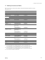
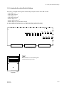
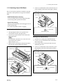
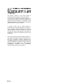
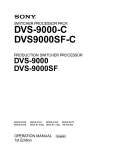
1-16. Removing/Reattaching Plug-in Board
1-16. Removing/Reattaching Plug-in
Board
5. When removing the EQ-84 or VPR-64 board, disconnect the harnesses from its board.
m
. Turn off the power and unplug the power cord before
removing/reattaching the board.
. When the plug-in board is replaced, refer to the maintenance manual, volume-1.
1. Fully loosen the two fixing screws.
2. Remove the upper lid (rear) by moving in the direction
indicated by the arrow.
Screw with stopper
Screw with stopper
Upper lid (rear)
EQ-84 board :
CN101 (G-3) ............. 6P White (Orange and Red)
CN200 (E-4) .............. 6P White (Yellow and Blue)
CN600 (A-3) ............. 3P White (Red)
CN700 (E-3) .............. 3P White (Yellow)
CN1600 (A-4) ............. 3P White (Orange)
CN1700 (E-4) .............. 3P White (Blue)
VPR-64 board :
*
CN100 (E-1/SDI-52) ............................. 1P Red
*
CN101 (F-1/SDI-52) ............................. 1P Yellow
*
CN500 (H-1/SDI-52) ............................ 1P Orange
*
CN501 (F-1/SDI-52) ............................. 1P Green
*
CN600 (H-1/SDI-52) ............................ 1P Blue
*: The VPR-64 board piggybacks the SDI-52 board,
therefore those connectors are mounted on the SDI52 board.
When reattaching the board, install in the reverse order of
removal.
m
. After inserting the board, push in the two folded eject
levers simultaneously to firmly connect the plug-in
board to the connector on the motherboard.
. When reattaching the upper lid (rear), be sure to insert
the protrusions in the square holes on the chassis, and
then secure the lid.
3. Open the eject levers on both ends of the board in the
direction of the arrows.
4. Hold the eject levers and slowly pull the board out.
2
1
1
1
Pulling out
1
3
EPR-1
DM-123
DPR-155
SS-89
APR-52
AU-272
EQ-84
3
2
Insertion
n
The AU-272 and EQ-84 boards should be removed
together due to their structural feature.
MSW-A2000
MSW-A2000P
VPR-64
(SDI-52)
The SDI-52 board is piggybacked onto the VPR-64 board.
Locations of Plug-in Boards
1-25
The material contained in this manual consists of
information that is the property of Sony Corporation.
Sony Corporation expressly prohibits the duplication of
any portion of this manual or the use thereof for any
purpose other than the operation or maintenance of the
equipment described in this manual without the express
written permission of Sony Corporation.
Le matériel contenu dans ce manuel consiste en
informations qui sont la propriété de Sony Corporation.
Sony Corporation interdit formellement la copie de
quelque partie que ce soit de ce manuel ou son emploi
pour tout autre but que des opérations ou entretiens de
l’équipement à moins d’une permission écrite de Sony
Corporation.
Das in dieser Anleitung enthaltene Material besteht aus
Informationen, die Eigentum der Sony Corporation sind.
Die Sony Corporation untersagt ausdrücklich die
Vervielfältigung jeglicher Teile dieser Anleitung oder den
Gebrauch derselben für irgendeinen anderen Zweck als
die Bedienung oder Wartung der in dieser Anleitung
beschriebenen
Ausrüstung
ohne
ausdrückliche
schriftliche Erlaubnis der Sony Corporation.
MSW-A2000
MSW-A2000P
MSW-A2000 (SY)
MSW-A2000P (SY) E
3-203-754-01 (1)
Sony Corporation
Communication System Solutions Network Company
Printed in Japan
2000. 2 08
©2000