1
HD DIGITAL VIDEOCASSETTE RECORDER
HDW-1800
HDW-D1800
INSTALLATION MANUAL
1st Edition
! WARNING
This manual is intended for qualified service personnel only.
To reduce the risk of electric shock, fire or injury, do not perform any servicing other than that
contained in the operating instructions unless you are qualified to do so. Refer all servicing to
qualified service personnel.
! WARNUNG
Die Anleitung ist nur für qualifiziertes Fachpersonal bestimmt.
Alle Wartungsarbeiten dürfen nur von qualifiziertem Fachpersonal ausgeführt werden. Um die
Gefahr eines elektrischen Schlages, Feuergefahr und Verletzungen zu vermeiden, sind bei
Wartungsarbeiten strikt die Angaben in der Anleitung zu befolgen. Andere als die angegeben
Wartungsarbeiten dürfen nur von Personen ausgeführt werden, die eine spezielle Befähigung
dazu besitzen.
! AVERTISSEMENT
Ce manual est destiné uniquement aux personnes compétentes en charge de l’entretien. Afin
de réduire les risques de décharge électrique, d’incendie ou de blessure n’effectuer que les
réparations indiquées dans le mode d’emploi à moins d’être qualifié pour en effectuer d’autres.
Pour toute réparation faire appel à une personne compétente uniquement.
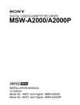
HDW-1800 (SY)
HDW-1800 (CN)
HDW-D1800 (SY)
HDW-D1800 (CN)
Serial No. 10001 and Higher
Serial No. 50001 and Higher
Serial No. 10001 and Higher
Serial No. 50001 and Higher
HDW-1800/D1800
ADVARSEL!
Lithiumbatteri-Eksplosionsfare ved fejlagtig
håndtering.
Udskiftning må kun ske med batteri
af samme fabrikat og type.
Levér det brugte batteri tilbage til leverandøren.
CAUTION
Danger of explosion if battery is incorrectly replaced.
Replace only with the same or equivalent type
recommended by the manufacturer.
Dispose of used batteries according to the
manufacturer’s instructions.
Vorsicht!
Explosionsgefahr bei unsachgemäßem Austausch
der Batterie.
Ersatz nur durch denselben oder einen vom
Hersteller empfohlenen ähnlichen Typ. Entsorgung
gebrauchter Batterien nach Angaben des
Herstellers.
ADVARSEL
Lithiumbatteri - Eksplosjonsfare.
Ved utskifting benyttes kun batteri som
anbefalt av apparatfabrikanten.
Brukt batteri returneres
apparatleverandøren.
VARNING
Explosionsfara vid felaktigt batteribyte.
Använd samma batterityp eller en likvärdig typ
som rekommenderas av apparattillverkaren.
Kassera använt batteri enligt gällande
föreskrifter.
VAROITUS
ATTENTION
Il y a danger d’explosion s’il y a remplacement
incorrect de la batterie.
Remplacer uniquement avec une batterie du même
type ou d’un type équivalent recommandé par le
constructeur.
Mettre au rebut les batteries usagées conformément
aux instructions du fabricant.
HDW-1800/D1800
Paristo voi räjähtää jos se on virheellisesti
asennettu.
Vaihda paristo ainoastaan laitevalmistajan
suosittelemaan tyyppiin.
Hävitä käytetty paristo valmistajan ohjeiden
mukaisesti.
1 (P)
Attention-when the product is installed in Rack:
Für Kunden in Deutschland
1. Prevention against overloading of branch circuit
When this product is installed in a rack and is
supplied power from an outlet on the rack, please
make sure that the rack does not overload the supply
circuit.
Entsorgungshinweis: Bitte werfen Sie nur entladene
Batterien in die Sammelboxen beim Handel oder den
Kommunen. Entladen sind Batterien in der Regel dann,
wenn das Gerät abschaltet und signalisiert “Batterie
leer” oder nach längerer Gebrauchsdauer der Batterien
“nicht mehr einwandfrei funktioniert”. Um
sicherzugehen, kleben Sie die Batteriepole z.B. mit
einem Klebestreifen ab oder geben Sie die Batterien
einzeln in einen Plastikbeutel.
2. Providing protective earth
When this product is installed in a rack and is
supplied power from an outlet on the rack, please
confirm that the outlet is provided with a suitable
protective earth connection.
3. Internal air ambient temperature of the rack
When this product is installed in a rack, please make
sure that the internal air ambient temperature of the
rack is within the specified limit of this product.
4. Prevention against achieving hazardous
condition due to uneven mechanical loading
When this product is installed in a rack, please make
sure that the rack does not achieve hazardous
condition due to uneven mechanical loading.
For the customers in the Netherlands
Voor de klanten in Nederland
Hoe u de batterijen moet verwijderen, leest u in de
Onderhoudshandleiding.
Gooi de batterij niet weg maar lever deze in als klein
chemisch afval (KCA).
5. Install the equipment while taking the operating
temperature of the equipment into consideration
For the operating temperature of the equipment, refer
to the specifications of the Operation Manual.
6. When performing the installation, keep the
following space away from walls in order to
obtain proper exhaust and radiation of heat.
Right, Left: 4 cm (1.6 inches) or more
Rear:
40 cm (16 inches) or more
2 (P)
For the customers in Taiwan only
HDW-1800/D1800
Table of Contents
Manual Structure
Purpose of this manual ........................................................... 2 (E)
Related manuals ..................................................................... 2 (E)
1. Installation
1-1.
Installation Procedure .............................................. 1-1 (E)
1-2.
Supplied Accessories ............................................... 1-1 (E)
1-3.
Operating Conditions ............................................... 1-1 (E)
1-4.
Power Supply ........................................................... 1-2 (E)
1-4-1.
1-4-2.
Voltage and Power Requirements .................. 1-2 (E)
Power Cord ..................................................... 1-2 (E)
1-5.
Installation Space ..................................................... 1-3 (E)
1-6.
Rack Mounting ........................................................ 1-4 (E)
1-7.
Matching Connectors and Cables ............................ 1-9 (E)
1-8.
Signal Inputs and Outputs ...................................... 1-10 (E)
1-9.
Switch Settings on Connector Panel ...................... 1-14 (E)
1-10. Switch Settings on Circuit Boards ......................... 1-15 (E)
1-10-1.
APR-80 Board .............................................. 1-15 (E)
1-11. Operation Mode Settings ....................................... 1-17 (E)
1-11-1. Operation Procedure of Destination
Selection Mode ............................................. 1-17 (E)
1-12. Removing/Reattaching Lower Control
Panel Unit .............................................................. 1-18 (E)
1-13. Switching Search Dial Mode ................................. 1-19 (E)
1-14. Reference System .................................................. 1-20 (E)
1-15. Settings and Adjustment when External
Equipment is Connected ........................................ 1-21 (E)
1-15-1. Settings for Time Code ................................ 1-21 (E)
1-15-2.
1-15-3.
VTR Constant Values Settings of Editor ..... 1-21 (E)
System Phase Alignment .............................. 1-22 (E)
1-16. Removing/Reattaching Plug-in Board ................... 1-22 (E)
1-17. Taking Out the Cassette in Tape Slacking ............. 1-23 (E)
Appendix A Setting Check Sheet
HDW-1800/D1800
1 (E)
Manual Structure
Purpose of this manual
This manual is the installation manual of the HD Digital Videocassette Recorder
HDW-1800/D1800.
This manual is intended for use by trained system and service engineers, and
provides the information that is required to install (environment, connection information, initial setting, etc.) and the setting check sheet.
Related manuals
Besides this “installation manual”, the following manuals are available for this unit.
. Operation Manual (Supplied with this unit.)
This manual is necessary for application and operation (and installation) of this
unit.
. Maintenance Manual (Available on request)
Volume-1 : Service Instruction
Volume-2 : Parts List, Block Diagrams, and Board Layouts
Volume-3 : Schematic Diagrams
These manuals describe the maintenace and service information (service overview, adjustments, board layouts, schematic diagrams, detailed parts list, etc.) for
this unit.
. “Semiconductor Pin Assignments” CD-ROM (Available on request)
This “Semiconductor Pin Assignments” CD-ROM allows you to search for
semiconductors used in Broadcast and Professional equipment.
The maintenance manual (volume-2) contains a complete list of semiconductors
and their ID Nos., and thus should be used together with the CD-ROM.
Part number: 9-968-546-0X
2 (E)
HDW-1800/D1800
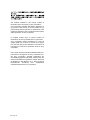
Section 1
Installation
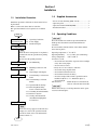
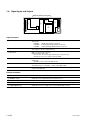
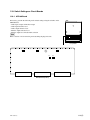
1-1. Installation Procedure
1-2. Supplied Accessories
Installation procedure of this unit is shown on the following flowchart.
Refer to each section about detail of each flow.
The operation manual is also required to do *-marked
flow.
.
.
.
.
Screws for rack mounting (PSW 4 x 16) .......................
Operation guide ..............................................................
Operation manual CD-ROM (PDF) ...............................
Installation manual .........................................................
4
1
1
1
1-3. Operating Conditions
Start
Determination of
installation place
1-3. Operating Conditions
1-4. Power Supply
1-5. Installation Space
Unpacking
n
When the unit is transported, it is required to
pack the unit into the specified new packing
materials.
Do not reuse the packing materials.
Rack mounting
*Connection
*Initial setup
1-6. Rack Mounting
1-7. Matching Connectors and
Cables
1-8. Signal Inputs and Outputs
1-9. Switch Settings on Connector
Panel
1-10. Switch Settings on Circuit
Boards
1-11. Operation Mode Settings
1-12. Removing/Reattaching
Lower Control Panel Unit
1-13. Switching Search Dial Mode
1-14. Reference System
1-15. Settings and Adjustment
when External Equipment
is Connected
c
Good air circulation is essential to prevent internal heat
build-up. Place the unit in location with sufficient air
circulation.
Do not block the ventilation holes of the cabinet and the
front and rear panels.
Operating temperature: 5 dC to 40 dC
Operating humidity: 25 % to 80 % (non-condensing)
Storage temperature: _20 dC to 60 dC
Locations to avoid:
. Areas where the unit will be exposed to direct sunlight
of any other strong lights.
. Areas near heat sources.
. Dusty areas or areas subject to vibration.
. Areas with strong magnetic field.
. Areas with much electrical noise.
. Areas with much static electricity.
. Areas that is impossible to find a specified room for
installation. (Refer to “1-5. Installation Space”.)
. Areas windtight.
Tilt allowance:
Within 30d (Do not slant the front
and rear of the unit more than 30d.)
c
Fix the unit securely to avoid drop when the unit is operated at not-horizontal place.
*Operation check
n
If an error message appears on the time data
display area, refer to the operation manual.
(For more details, refer to the maintenance
manual volume-1.)
End
HDW-1800/D1800
1-1 (E)
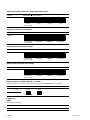
1-4. Power Supply
1-4-2. Power Cord
1-4-1. Voltage and Power Requirements
This unit does not come with a power cord.
To get a power cord, please contact your local Sony Sales
Office/Service Center.
This unit’s power line has a switching regulator.
c
Be sure to operate the unit within the range of following
power voltage.
Power voltage:
AC 100 to 240 V ± 10 %
Power frequency:
50 Hz or 60 Hz
Power consumption: Maximum 170 W
(With all of the presumed optional kits.)
Rush current:
10 A (Power voltage 100 V)
33 A (Power voltage 240 V)
n
AC power supply is required a capacity which is commensurate with rush current.
If the capacity of the AC power supply is not enough, the
breaker of AC power of a supply side may operate or this
unit may not operate normally.
w
Use the specified power cord only when connecting the
AC power. Never use a injured power cord.
For customers in the U.S.A. and Canada:
1 Power cord 125 V 10 A (2.4 m):
! 1-551-812-31
2 Plug holder (Brown):
3-613-640-01
1
2
For customers in the United Kingdom:
1 Power cord 250 V 10 A (2.0 m):
2 Plug holder (Brown):
1
2
AC inlet
! 1-777-823-12
3-613-640-01
AC inlet
For customers in European countries except the United
Kingdom:
1 Power cord 250 V 10 A (2.0 m):
! 1-551-631-15
2 Plug holder (Brown):
3-613-640-01
1
2
For customers in the China:
1 Power cord 250 V 10 A (1.8 m):
2 Plug holder (Brown):
1
2
AC inlet
! 1-783-481-42
3-613-640-01
AC inlet
If the unit is used in the area except above, please contact
your local Sony Sales Office/Service Center.
1-2 (E)
HDW-1800/D1800
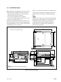
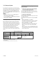
1-5. Installation Space
When installing, the installation space must be secured in
consideration of the ventilation and service operation.
. Do not block the ventilation slots at the left side and
right side panels, and vents of the fans.
. Leave a space around the unit for ventilation.
. Leave more than 40 centimeters of space in the rear of
the unit to secure the operation area.
When the unit is installed on the desk or the like, leave at
least four centimeters of space in the left and right sides.
Leaving 40 centimeters or more of space above the unit is
recommended for service operation.
Moreover, an air flow that is effective in cooling the unit is
essential. If the ventilation is not enough, the unit may be
damaged because of an increase of the internal temperature.
n
This unit is air-cooled by the five fans. The operation with
the upper lid is removed affects the air cooling by the fans.
Complete the work in a short time as possible when
operating the unit for inspection with the upper lid removed. If it takes a long time, blow to the unit by an
electric fan to cool the unit.
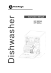
544
416(Rail-installed width)
427(Unit width)
(Mass of this unit : approx. 22 kg)
45.5
533
577(Maximum traveling distance)
105
454
15.9
19.5
87
87
70.6
112
31
174
87
31
36.2
481
465
45
31.5
364
427
34
12.7
123.8
263.5
48
n Remove the feet when rack mounting.
415.9
457.5
(38.5)
Unit : mm
Dimensions when Rack-Mounting
HDW-1800/D1800
1-3 (E)
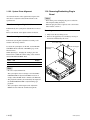
1-6. Rack Mounting
Parts Packed in RMM-131
Explains how to mount this unit into a 19-inch standard
rack.
Two positions (center and low) are available to attach the
inner rails of the slide rails to this unit.
Be sure to mount this unit (*) into a rack accurately
following the procedure and notes mentioned below.
*: The center position only is available for the units listed
below.
MSW-A2000 : Serial No. 10001 through 10180
MSW-A2000P : Serial No. 40001 through 40520
w
. To prevent toppling over the rack, fix it on the horizontal
and firm floor securely with bolts, etc.
. When installing the unit in an Outside Broadcasting van,
be sure to fix the unit to the rack using the screws and
ornamental washers supplied with the rack mount kit.
.
.
.
.
.
.
.
.
.
.
.
c
. Use the specified rack mount rail.
The use of other rail of low strength may drop the unit
and cause the risk of injury.
. Mount the unit into a rack with a steady posture.
Slide rails ..........................................................
Rack angles (handles) with lock mechanism ...
Rail brackets .....................................................
Plate nuts (large) ..............................................
Plate nuts (small) ..............................................
Screws (B4 x 8) ...............................................
Hexagon socket head cap screws .....................
Flat washers ......................................................
Screws (RK5 x 14) ..........................................
Ornamental washers .........................................
L-shaped hexagon wrench ...............................
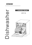
Rack Mounting Procedure
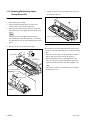
. Removing the feet
1. Set the unit its side panel down.
2. Unscrew the four screws to remove the feet from the
bottom plate of the unit.
3. Set the unit in a horizontal position.
Feet
m
. When other equipment with built-in hard disk drive is
already mounted in the same rack for mounting this unit,
turn off the power of the equipment before mounting this
unit.
. Connect long enough cables on the connector panel,
considering that the unit is pulled out from the rack.
. Do not operate this unit without the upper lid and bottom
plate except when servicing it.
. Adjust the temperature inside the rack within the range
of the unit’s operating temperature.
(Refer to Section 1-3.)
Specified Rack Mount Kit
2
2
4
4
4
8
8
8
2
2
1
PS4 x 20
Feet
PS4 x 20
RMM-131 (Optional accessory)
m
. When mounting this unit into Sony LMS (Library
Management System) VTR console, it is necessary to
modify the VTR console.
. When mounting this unit into Flexicart, be sure to use
the specified kit below.
VTR Mounting kit: BKFC-53/3
. The RMM-130 rack mount kit also can be used for the
center position.
1-4 (E)
n
Keep these screws and the feet.
When operating the unit after demounting it from the rack,
be sure to reattach the feet.
Tightening torque: 98 x 10_2 N . m {10 kgf . cm}
HDW-1800/D1800
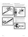
. Attaching the inner rails
4. Pull out the inner rails from the two intermediate rails.
5. While pressing the stopper of the inner rail in the
direction of the arrow A in the figure, pull the inner
rail out in the direction of the arrow B.
. Attaching the rack angles (handles)
8. Remove the four screws from both sides (left and
right) of the unit.
B4 x 6
Intermediate rail
B4 x 6
Inner rail
Outer rail
A
Stopper
B4 x 6
B
6. Remove the ten screws from both sides (left and right)
of the unit as shown in the figure below.
7. Attach the two inner rails to both sides (left and right)
of unit with the removed screws in the step 6.
Tightening torque: 120 x 10_2 N . m {12.2 kgf . cm}
m
. Be sure to use the (B4 x 6) screws when attaching
the inner rail. The use other-sized screws may cause
a malfunction.
. Pay attention not to fasten the screws to the screw
holes other than actually used screw holes for fixing
the inner rails on both sides of the unit.
If unnecessary screws are fastened, rack mounting
will be unenabled.
Inner rail
n
Keep these screws (B4 x 6).
Be sure to use these screws when directly fixing the
side panels without the rack angles.
The use of longer screws such as the screws (PSW 4 x
16) for fixing the rack angles of RMM-130 will cause
a malfunction of the unit.
9. Attach the two rack angles to both sides (left and right)
of the unit with the four screws (PSW4 x 16).
Tightening torque: 120 x 10_2 N . m {12.2 kgf . cm}
n
. For RMM-131, screws with stop washers are used
for fixing the rack angles.
. For RMM-130, use the supplied screws PSW4 x 16
as shown in Fig. 1.
B4 x 6
B4 x 6
Inner rail
n
When replacing a 5U size Sony VTR with this unit, attach
the inner rails to the low position, so that the bottom of the
unit becomes same as that of the 5U size VTR.
Rack angle
PSW4 x 16
PSW
4 x 16
Rack angle
Rack angle
Fig.1 For RMM-130 (Left side)
HDW-1800/D1800
1-5 (E)
. Loosely attaching the rail brackets
10. Slide the intermediate rail as shown in the figure, and
then loosely attach the rear rail bracket to the outer rail
with a plate nut (large) and the two screws.
. Attaching the outer rails
12. Loosely attach the two outer rails to the middle of the
4U space in the rack for mounting this unit, with the
eight hexagon socket head cap screws, eight flat
washers, and four plate nuts (small).
Plate nut (small)
Plate nut (large)
Rail bracket
Outer rail
B4 x 8
Rail
Rail bracket
By 4U
Flat washer
Hexagon socket
head cap screw
Intermediate rail
2U
L-shaped hexagon wrench
11. Slide the ball retainer in the direction of the arrow, and
then loosely attach the front rail bracket to the outer
rail with a plate nut (large) and the two screws.
Outer rail
Plate nut (large)
Rail bracket
Intermediate rail
13. As shown in the following figure, adjust each frontside position of the outer rails on both sides (left and
right) so that the distance from the surface of the rack
to the tip of the rail becomes within the range of 50 to
55 millimeters.
14. Fully tighten the eight screws (B4 x 8) fixing the four
rail brackets.
Tightening torque: 120 x 10_2 N . m {12.2 kgf . cm}
Ball retainer
Rack
B4 x 8
Outer rail
Rail bracket
50 to 55 mm
Rack angle
1-6 (E)
B4 x 8
HDW-1800/D1800
15. Check that the two intermediate rails attached to the
rack are parallel.
A
. Mounting in rack
c
Be sure to carry the unit by the two persons or more.
17. Slide each ball retainer of intermediate rails on both
sides (left and right) in the direction of the arrow.
Intermediate rail
Intermediate rails
Ball retainer
A'
Width : A = A' = 416 mm
16. To fix the two outer rails to the rack, fully tighten the
eight loosely fitted hexagon socket head cap screws in
step 12 using the L-shaped hexagon wrench.
18. Pull equal length of each rail on both sides out.
19. Lift the unit holding the gripes on both sides, slowly
insert the inner rails into the intermediate rails.
20. While pressing each stopper of inner rails on both
sides, slowly push the unit into the rack.
c
Be careful not to catch your finger or hand in rack
mount rail.
Stopper
Release button
Intermediate rail
Stopper
Inner rail
Release button
n
Pushing the unit in the depths of the rack, the lock mechanism prevents the unit from being pulled out.
To pull the unit out of the rack, pull the unit while pressing
the release buttons of the rack angles.
HDW-1800/D1800
1-7 (E)
21. Slide the unit in and out from the rack about three
times and check that the slide rails move smoothly.
If they are not smoothly, demount the unit and go back
to “Attaching the outer rails” (step 12).
c
When demounting the unit, carry it by the two persons
or more.
n
This unit does not have the feet at this operating.
Put down the unit on the floor or other, being careful
not to damage the unit.
22. Push the unit in the depths of the rack. The unit is
fixed to the rack by the lock mechanism.
Attempt to pull the rack angles and confirm that the
unit cannot be pulled out of the rack.
w
When installing the unit in an Outside Broadcasting
van, be sure to fix the unit to the rack using the screws
and ornamental washers supplied with the rack mount
kit.
Tightening torque: 120 x 10_2 N . m {12.2 kgf . cm}
n
When the unit is not fixed to the rack or the clearances
between the rack angle and rack are existed, it is
necessary to perform the adjustment for the lock
mechanism.
Refer to the RMM-131 installation guide for more
detailed information.
Release button
Ornamental
washer
RK5 x 14
RK5 x 14
Release button
Ornamental washer
1-8 (E)
HDW-1800/D1800
1-7. Matching Connectors and Cables
When external cables are connected to the connector of this unit, the hardware listed below (or equivalents) must be used.
Panel indication
Matching connector (cable)
Sony part No.
AUDIO INPUT
TIME CODE IN
XLR 3P, MALE
1-508-084-00
AUDIO OUTPUT
MONITOR OUT
TIME CODE OUT
XLR 3P, FEMALE
1-508-083-00
REF INPUT
VIDEO OUTPUT
BNC 75Z, MALE
1-569-370-12
AUDIO INPUT (AES/EBU)
AUDIO OUTPUT (AES/EBU)
BNC 75Z, MALE *1
1-569-370-12
REMOTE 2
PARALLEL I/O (50P)
D-SUB 50P, MALE and
JUNCTION SHELL 50P
1-565-516-11
1-563-379-11
REMOTE 1-IN (9P)
REMOTE 1-OUT (9P)
9P remote control cable (RCC-G series)
or
D-SUB 9P, MALE and
JUNCTION SHEEL 9P
_
or
1-560-651-00
1-561-749-00
RS-232C
D-SUB 9P, FEMALE
1-563-815-21
CONTROL PANEL
20P, MALE
(exclusive connecting cable)
1-833-620-11
VIDEO CONTROL (9P)
D-SUB 9P, MALE and
JUNCTION SHELL 9P
1-561-651-00
1-561-749-00
HDV IN (OPTION)
Specified by optional kit
_
HD SDI
BNC 75Z, MALE
*2
1-569-370-12
SDI
BNC 75Z, MALE *3
1-569-370-12
PHONES
JM-60 stereo phone plug
_
Remarks
Upper control panel connector
*1: Coaxial cable length : max. 600 meters (Reference value based on HDW series)
It is recommended to connect the BELDEN 8281 cable or equivalent to this connector.
*2: Coaxial cable length : max. 100 meters (Reference value based on HDW series)
It is recommended to connect the BELDEN 1694A cable or equivalent to this connector.
*3: Coaxial cable length : max. 200 meters (Reference value based on HDW series)
It is recommended to connect the BELDEN 8281 cable or equivalent to this connector.
HDW-1800/D1800
1-9 (E)
1-8. Signal Inputs and Outputs
Reduced drawing of rear panel
3
1
5
2
6
4
Input connectors
1 AUDIO INPUT
XLR 3-pin x 2 (1 set : CH1, CH2)
Analog audio
LOW OFF : _60 dBu, high impedance, balanced
HIGH OFF : +4 dBu (Standard), high impedance, balanced
HIGH ON : +4 dBm (Standard), 600 Z termination, balanced
1 TIME CODE IN
XLR 3-pin x 1
Time code 0.5 to 18 V p-p, 10 kZ, balanced
2 REF. INPUT
BNC x 2 in loop through connection
Outside reference video signal
SD : 0.3 V p-p, 75 Z, sync negative (Black burst or composite sync)
HD : 0.6 V p-p, 75 Z, sync negative (Ternary SYNC)
3 AUDIO INPUT (AES/EBU)
BNC x 2 (1 set : CH1/2, CH3/4)
Digital audio
AES/EBU format, complies with AES-3id-1995
5 HD SDI INPUT
BNC x 1
Serial digital interface (1.485 Gbit/s), complies with SMPTE 292M
6 HDV IN (OPTION)
i.LINK 6-pin x 1
Complies with IEEE1394
Remote connectors
4 REMOTE 2 PARALLEL I/O (50P) ***
D-SUB 50P connector
4 REMOTE1-IN (9P)
D-SUB 9P connector (RS-422A interface), Remote control
4 REMOTE1-OUT (9P)
D-SUB 9P connector (RS-422A interface), Remote control
4 RS-232C
D-SUB 9P connector (RS-232C interface) for ISR (Interactive Status Reporting)
4 VIDEO CONTROL (9P)
D-SUB 9P connector for a TBC remote controller (HKDV-900) connection
*** : Refer to Optional “Interface manual” for details.
1-10 (E)
HDW-1800/D1800
Output connectors
1 AUDIO OUTPUT
XLR 3-pin x 2 (1 set : CH1, CH2)
Analog audio
+4 dBm (Standard) (600 Z load), low impedance, balanced
1 TIME CODE OUT
XLR 3-pin x 1
Time code 2.2 V p-p, low impedance, balanced
1 MONITOR OUTPUT
XLR 3-pin x 2 (1 set : L and R)
Analog audio
+4 dBm (Standard) (600 Z load), low impedance, balanced
2 VIDEO OUTPUT, COMPOSITE
BNC x 3 (including 1 for character superimpose)
Analog composite video 1.0 V p-p, 75 Z, sync negative
3 AUDIO OUTPUT (AES/EBU)
BNC x 4 (1 set : CH1/2, CH3/4, CH5/6, and CH7/8) or
BNC x 2 (1 set : CH1/2, CH3/4)
Digital audio
AES/EBU format, complies with AES-3id-1995
5 HD SDI OUTPUT
BNC x 3 (including 1 for character superimpose)
Serial digital interface (270 Mbit/s), complies with SMPTE 292
5 SDI OUTPUT
BNC x 3 (including 1 for character superimpose)
Serial digital interface (270 Mbit/s), complies with SMPTE 259M & ITU-R BT.656
PHONES
(Upper control panel)
JM-60 stereo phone jack
Analog audio
up to _12 dBu (8 Z load), unbalanced
Other
Memory stick
(Switch panel)
HDW-1800/D1800
Memory stick x 1
Applicable memory stick (8 MB to 128 MB)
1-11 (E)
REMOTE 2 PARALLEL I/O: 50-pin (female)
External view
17
1
33
18
50
34
Pin No.
I/O *1
Setting change *2 Signal
Description
1
IN
O
FF
CLOSURE SW (FF)
2
OUT
X
REC SW
PANEL REC SW OUT
3
OUT
X
PLAY SW
PANEL PLAY SW OUT
4
OUT
X
STOP SW
PANEL STOP SW OUT
5
OUT
X
ENTRY SW
PANEL ENTRY SW OUT
6
OUT
X
REF SYSTEM ALARM
Non-REFERENCE
7
OUT
X
CF LOCK
COLOR FRAME LOCK STATUS
8
OUT
X
DRUM LOCK
LOCK STATUS OF DRUM SERVO
9
OUT
X
CAP LOCK
LOCK STATUS OF CAPSTAN SERVO
10
OUT
O
CUE PRESET
EDIT PRESET STATUS of the CUE Channel
11
OUT
O
TC PRESET
EDIT PRESET STATUS of the TC Channel
12
OUT
O
OXIDE/METAL
OXIDE/METAL TAPE STATUS
13
OUT
O
TAPE THICKNESS
TAPE THICKNESS STATUS
14
OUT
X
SPARE
SPARE
15
OUT
X
SPARE
SPARE
16
——
——
+12V
(Maximum output current 50 mA)
17
——
——
GND
SIGNAL GND
18
IN
O
PREROLL
CLOSURE SW (PREROLL)
19
IN
O
STBY ON
CLOSURE SW (STANDBY ON)
20
IN
O
REW
CLOSURE SW (REW)
21
IN
O
ENTRY
CLOSURE SW (ENTRY IN)
22
IN
O
STBY OFF
CLOSURE SW (STANDBY OFF)
23
IN
O
EJECT
CLOSURE SW (EJECT)
24
OUT
X
REC
REC STATUS
25
OUT
X
CH CONDITION RED
CHANNEL CONDITION RED STATUS
26
OUT
O
ASSEMBLE PRESET
ASSEMBLE PRESET STATUS
27
OUT
O
EDIT OUT
EDIT STATUS
28
OUT
O
EJECT OUT
EJECT STATUS
29
OUT
O
ANALOG/DIGITAL
ANALOG/DIGITAL STATUS
30
OUT
O
REEL HUB
REEL HUB STATUS
31
OUT
X
REM2 SETTING DATA RESET REMOTE2 SETTING DATA RESET STATUS
32
OUT
X
ALL REC INHIBIT
33
——
——
GND
34
IN
O
PLAY
CLOSURE SW (PLAY)
35
IN
O
STOP
CLOSURE SW (STOP)
ALL REC INHIBIT STATUS
(Continue)
1-12 (E)
HDW-1800/D1800
(Continued)
Pin No.
I/O *1
Setting change *2 Signal
Description
36
IN
O
REC
CLOSURE SW (REC)
37
OUT
X
REV LAMP
REV LAMP STATUS
38
OUT
O
DA2 PRESET
DA2 EDIT PRESET STATUS
39
OUT
O
DA1 PRESET
DA1 EDIT PRESET STATUS
40
OUT
X
FWD LAMP
FWD LAMP STATUS
41
OUT
O
DA4 PRESET
DA4 EDIT PRESET STATUS
42
OUT
O
DA3 PRESET
DA3 EDIT PRESET STATUS
43
OUT
X
STOP
STOP STATUS
44
OUT
O
VIDEO PRESET
VIDEO EDIT PRESET STATUS
45
OUT
O
INSERT PRESET
INSERT EDIT PRESET STATUS
46
OUT
X
STBY ON
STANDBY ON STATUS
47
OUT
X
PLAY
PLAY STATUS
48
OUT
X
REMOTE
REMOTE STATUS
49
OUT
X
ALARM
SYSTEM ALARM STATUS
50
OUT
O
PREROLL
PREROLL STATUS
*1: Input ; 47 kZ pull up to +5 V (close/open)
Output ; 10 kZ pull up to +5 V (0 V or open)
*2: The pins described as O mark are possible to change the setting.
Refer to the optional interface manual for changing the setting.
REMOTE1-IN: 9-pin (female)
REMOTE1-OUT: 9-pin (female)
RS-232C: 9-pin (male)
External view
5
External view
1
9
1
6
5
6
9
Pin No.
Signal
Pin No.
Signal
1
GND
1
DCD ; Data Carrier Detect (Input)
2
RM TX(_)
2
RXD ; Received Data (Input)
3
RM RX(+)
3
TXD ; Transmitted Data (Output)
4
GND
4
DTR ; Data Terminal Ready (Output)
5
PRIORITY
5
SG ; Signal Ground
6
GND
6
DSR ; Data Set Ready (Input)
7
RM TX(+)
7
RTS ; Request to Send (Output)
8
RM RX(_)
8
CTS ; Clear to Send (Input)
9
GND
9
NC
HDW-1800/D1800
1-13 (E)
VIDEO CONTROL: 9-pin (female)
External view
5
1
9
1-9. Switch Settings on Connector Panel
When the unit is installed, be sure to perform the following
setup.
Refer to the operation manual “Section 2 Location and
Function of Parts” for setup.
6
. Analog audio input level/600 Z termination switches
. 75 Z termination switch of reference video input
Pin No.
Signal
1
GND
2
RM TX (_)
3
RM RX (+)
4
GND
5
——
6
GND
7
RM TX (+)
8
RM RX (_)
9
GND
HDV IN (OPTION): 6-pin
External view
1
3
5
Pin No.
Signal
1
VP
2
VG
3
NTPB
4
TPB
5
NTPA
6
TPA
1-14 (E)
2
4
6
HDW-1800/D1800
1-10. Switch Settings on Circuit Boards
1-10-1. APR-80 Board
If necessary, perform the following audio-related settings using the switches on the
APR-80 board.
. Audio input, output, and monitor output
. Audio input reference level
. Audio output reference level
. Monitor output reference level
. Monitor output level, fixed/variable selection
n
Refer to Section 1-16 for removing and reattaching the plug-in boards.
< Top View >
A
B
C
D
E
F
G
1
S1901
S1900
H
J
APR-80 K
A
L
M
N
P
S1902
2
S2001
S2000
3
4
5
6
APR-80 Board (Side A)
HDW-1800/D1800
1-15 (E)
Audio input, output, and monitor output headroom settings
1
2
3
4
5
6
7
8
1
2
3
4
5
6
7
8
O
N
O
N
1
2
3
4
5
6
7
8
18 dB
16 dB
12 dB
20 dB
(Factory setting)
O
N
O
N
S1902-1, 2
1
2
3
4
5
6
7
8
\ : Knob position)
Switch state (\
Ref. No.
Audio input reference level settings
O
N
O
N
1
2
3
4
5
6
7
8
1
2
3
4
5
6
7
8
1
2
3
4
5
6
7
8
0 dBm/600 Z
_3 dBm/600 Z
_20 dBm/600 Z
+4 dBm/600 Z
(Factory setting)
O
N
O
N
S1902-3, 4
1
2
3
4
5
6
7
8
\ : Knob position)
Switch state (\
Ref. No.
Audio output reference level settings
O
N
O
N
1
2
3
4
5
6
7
8
1
2
3
4
5
6
7
8
1
2
3
4
5
6
7
8
0 dBm/600 Z
_3 dBm/600 Z
_20 dBm/600 Z
+4 dBm/600 Z
(Factory setting)
O
N
O
N
S1902-5, 6
1
2
3
4
5
6
7
8
\ : Knob position)
Switch state (\
Ref. No.
Monitor output reference level settings
O
N
O
N
1
2
3
4
5
6
7
8
1
2
3
4
5
6
7
8
1
2
3
4
5
6
7
8
0 dBm/600 Z
_3 dBm/600 Z
_20 dBm/600 Z
+4 dBm/600 Z
(Factory setting)
O
N
O
N
S1902-7, 8
1
2
3
4
5
6
7
8
\ : Knob position)
Switch state (\
Ref. No.
Monitor output level switching (fixed or variable)
When the variable level is selected, the level is adjusted with the PHONES level control knob.
Channel
Ref. No.
L
S2001
R
S2000
\ : Knob position)
Switch state (\
Fixed
1
2
Variable
O
N
1
2
O
N
(Factory setting)
Factory use
n
Never change the setting.
Ref. No.
Switch state
S1900, S1901
All OFF
1-16 (E)
HDW-1800/D1800
1-11. Operation Mode Settings
When turning on the POWER switch for the first time or
after executing “M49: RESET ALL SETUP” in the
maintenance mode, the mode for selecting a destination (J
or SYL) appears.
Select a destination following the operation procedure of
the destination selection mode.
Once a destination is selected, this mode does not appear
when the POWER switch is turned on and the unit operates
with the selected destination.
m
. Be sure to select a destination before use.
If no destination is selected, the unit will not perform the
playback and recording operations correctly even though
these operations are enabled.
. Destination: “J” is for the models for Japan, and “SYL”
is for the models for the countries other than Japan.
1-11-1. Operation Procedure of Destination
Selection Mode
1. When no destination has not been selected, turning on
the POWER switch displays the following indication
in the menu display area of the control panel.
2. Pressing the F3 (_) or F4 (+) button selects the
destination 50 : SYL, 59.94 : SYL or 59.94: J.
DESTINATION SETTING
* NO-SET
50:SYL
59.94:SYL
59.94:J
Select DESTINATION.
Push SET button.
3. Press the F9 (SET) button.
. Pressing the F9 (SET) button accepts the selected
destination.
. Screen 2 appears after Screen 1 is displayed for
about 10 seconds as shown in the figure. Then turn
off the POWER switch.
Screen 1
DESTINATION SETTING
INITIALIZING...
Screen 2
About 10 seconds
DESTINATION SET
COMPLETE
59.94:SYL
TURN OFF/ON POWER !!
To return the destination to the “NO-SET” status:
Reset all the unit settings to the factory settings using
“M49: RESET ALL SETUP” of the maintenance mode.
For details about the maintenance mode, refer to Section 3
in the Maintenance Manual Volume-1.
n
All the settings, including the setup menu, are reset.
HDW-1800/D1800
1-17 (E)
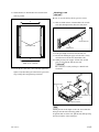
1-12. Removing/Reattaching Lower
Control Panel Unit
5. Lightly draw the lower control panel unit toward you,
and then lift it upward.
Removal
1. Turn off the power of VTR.
2. After pressing the unlock button, open the lower
control panel as shown in the figure below.
3. Disconnect the cable from the connector on the back
side of the lower control panel unit and from the cord
holder.
n
Check the power of the VTR is turned off before
disconnecting the cable. Disconnecting or connecting
the cable in the power-on state will damage the control
panel.
Lower control panel unit
Reattaching
4. Remove the two screws shown in the figure.
POWER
O
Unlock button
I
Power OFF
Unlock button
BVTT3 x 6
Lower control panel unit
Reattach the lower control panel unit in the reverse order
of removal. Yet when reattaching, use care about following
points.
. If the arms are not open, press the both side of unlock
buttons, then secure the arm to the 90 d position.
. When reattaching the lower control panel unit to the
arms, place the lower control panel which square holes
aligned to the unlock buttons, and slide it slightly to the
VTR.
. Check the screw holes are visible from your side before
tightening the screws.
Back view
Cable
BVTT3 x 6
Cable holder
Connector
1-18 (E)
HDW-1800/D1800
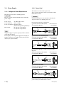
1-13. Switching Search Dial Mode
There are two kinds of operation to switch the mode of the
search dial on the lower control panel.
4. Check to see that the shaft of the search dial is not seen
in the round hole of the mode selection plate, and then
tighten the screw.
Back view
. Button selecting
To enter the shuttle mode, press the SHUTTLE button.
To enter the jog mode, press the JOG button.
To enter the variable mode, press the VAR button.
Mode selection plate
Screw
. Search dial pressing
When you press the search dial, the search dial mode
switches in order to shuttle, jog, variable.
It is possible to prohibit a manner of switching.
Prohibiting Search Dial Pressing
Round hole
1. After pressing the unlock buttons, open the lower
control panel as shown in the figure below.
2. Loosen a screw on the backside of the search dial as
shown in the figure.
n
If it is difficult to loosen the screw, remove the lower
control panel unit in advance.
(Refer to Section 1-12.)
3. Slide the mode selection plate in the direction indicated by the arrow until it contacts the portion A.
Unlock button
The shaft is not seen.
Allowing Search Dial Pressing
1. Open the lower control panel. (Operation side up)
2. Loosen a screw on the backside of the search dial as
shown in the figure.
3. Fully slide the mode selection plate in the direction
indicated by the arrow.
4. Check to see that the shaft of the search dial is seen in
the round hole of the mode selection plate, and then
tighten the screw.
Back view
Unlock button
Mode selection plate
Screw
Lower control panel unit
Back view
Mode selection plate
Search dial
Screw
Search dial shaft
Round hole
The shaft is seen.
Portion A
HDW-1800/D1800
1-19 (E)
1-14. Reference System
Alarm Display for Video Input Signal and
Reference Signal
For each reference signal, either of an external reference
video signal (*3) or input video signal (*4) is automatically
selected according to the setting of function menu item
OUT REF, the setting of setup menu ITEM-309, and the
operation mode (PB/EDIT/REC) of this unit. (Refer to the
table 1-14-1 below.)
m
. To select the video input, use F1 (VIDEO IN) in the
function menu page P01 : HOME.
. To set the OUT REF, use F2 (REF VID) in the function
menu page P03 : VID PROC.
Audio Signal Independent Recording
Even if an input video signal is selected as the reference
signal, the reference signal is automatically selected to an
external reference video signal for the period in which the
no input video signal is input. When no external reference
video signal is input, the internal-generated reference
signal is automatically selected for the period.
An audio signal can be independently recorded by this
system even if no reference video signal is input from the
outside.
1. Blink of the selected input video indication
area of the video input selection
The selected input video indication area on the system
information blinks when signal is not input to the connector selected by the video input selection.
2. Blink of the STOP button
The button blinks when the reference signal is not locked
to an input video signal.
(This function can be canceled in the setup menu ITEM105.)
. When the OUT REF is set to “INPUT”:
The STOP button blinks when the signal is not input to
the connector selected by the video input selection.
. When the OUT REF is set to “REF”:
The STOP button blinks in the following either cases.
When no reference signal is input to REF. VIDEO
connector.
When the reference video signal (REF.VIDEO input) is
not synchronized with an input video signal selected by
the video input selection.
Table 1-14-1. Reference System
Menu ITEM-309
EXT
OUT REF
—————
Operation mode
—————
AUTO
REF
PB
EDIT (*1)
INPUT
EDIT (*2)
REC
—————
Video output process
Digital audio
External Reference Video (*3)
Input Video (*4)
Servo system
*1: When the setup menu ITEM-309 is set to “AUTO1”.
*2: When the setup menu ITEM-309 is set to “AUTO2”.
*3: REF. VIDEO input
*4: The input video signal is selected by the video input selection.
1-20 (E)
HDW-1800/D1800
1-15. Settings and Adjustment when External Equipment is Connected
1-15-1. Settings for Time Code
To set the TIME CODE, open the the P02 : TC page on the function menu.
When Editing with an Editor (BVE-2000, etc.) Capable of the 1st Edit
When this unit is used by connecting to an editor, set as follows.
Button
Item (Display)
Setting
F1
TCG SOURCE (TCG SRC)
INTERNAL
F2
TCG PRESET/REGEN (TCG MODE)
PRESET
F3
TCG RUN (TCG RUN)
FREE
When Editing with Direct Machine-to-Machine (VTR to VTR)
n
The setup menu ITEM-610 : REGEN CONTROL MODE setting data must be set to “AS&IN”.
Button
Item (Display)
Setting
F1
TCG SOURCE (TCG SRC)
INTERNAL
F2
TCG PRESET/REGEN (TCG MODE)
PRESET
F3
TCG RUN (TCG RUN)
FREE
1-15-2. VTR Constant Values Settings of Editor
Set the VTR constant values according to the table 1-15-2 below when the editor which needs the setting
of VTR constant values is connected. Moreover, the change of VTR constant values are required when
the operation mode is switched by setup menu of this unit.
n
When remote-controlling this unit by the editor, set the setup menu ITEM-401: FUNCTION MODE
AFTER CUE-UP to “STOP”.
Table 1-15-2. VTR Constant Values Settings of Editor
Model
Operation
Mode
VTR CONSTANT 1
1
HDW-1800,
HDW-D1800
59.94, 29.97P 20
2
E2
3
00
Data No.
4
5
96
07
6
07
VTR CONSTANT 2
7
03
1
2
3
Data No.
4
5
*1
0D
08
00
00
*1
8
8A
81
6
7
8
3D
FF
5A
21
E2
00
7D
07
07
03
8A
0D
07
00
00
83
3B
FF
4B
24P, 23.98P 22
E2
00
78
07
07
03
8A*1 0D
07
00
00
83
3B
FF
4B
50, 25P
(Standard value is expressed in hexadecimal.)
*1: Set the data of No.8 of the VTR CONSTANT 1 to “0A” for the following editors.
. BVE-900 ROM versions earlier than 1.08
. BVE-600 ROM versions earlier than 1.01
HDW-1800/D1800
1-21 (E)
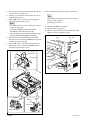
1-16. Removing/Reattaching Plug-in
Board
1-15-3. System Phase Alignment
An external reference video signal must be input to this
unit after it is adjusted so that SC-H conforms to the
specifications.
When Connecting to a Digital Switcher
m
. Turn off the power and unplug the power cord before
removing/reattaching the board.
. When the plug-in board is replaced, refer to the maintenance manual, volume-1.
Fundamentally, the system phase adjustment is not necessary.
Refer to the manual of the digital switcher for details.
Removing
When Connecting to an Analog Switcher
1. Fully loosen the two fixing screws.
2. Remove the upper lid (rear) assembly by moving in
the direction indicated by the arrow.
Perform the system phase adjustment according to the
manual of the analog switcher.
To adjust the system phase of this unit, use the MULTI
CONTROL knob at the P03 : VID PROC page on the
function menu.
When adjusting (i.e. changing the settings), press the
button below to blink the current setting value, and then
turn the MULTI CONTROL knob.
Button
Item
Display
F3
SYSTEM SYNC PHASE
SYNC PHS
F4
SYSTEM SYNC PHASE (fine djustmen)
SYNC FIN
Screw with stopper
Upper lid (rear)
assembly
Screw with stopper
m
. Be sure to adjust in PB mode.
The system phase does not change even if the SYNC
PHS/SYNC FIN is adjusted in the REC mode, but it
changes when the REC mode is shifted to the PB mode.
. The playback sound may be momentarily interrupted if
the SYNC PHS/SYNC FIN is adjusted during tape
playback.
. The system phase of SD output can be adjusted in
ITEM-719 and -720 of the extended setup menu.
1-22 (E)
HDW-1800/D1800
3. Open the eject levers on both ends of the board in the
direction of the arrows.
4. Hold the eject levers and slowly pull the board out.
1
1
2
1
1
3
When slacking the tape in this unit, follow the steps below
to take out the cassette tape.
n
Being careful not to damage the tape, take out the cassette
tape with care.
3
2
Pulling out
1-17. Taking Out the Cassette in Tape
Slacking
Insertion
n
The SY-340 and DU-386 boards should be removed
together due to their structural feature.
1. Turn off the power.
2. Fully loosen the fixing screw.
3. Slide the knobs on upper lid (front) assembly each in
the inside. (Move the knobs to the outside to fix the
upper lid (front) assembly.
4. Remove the upper lid (front) assembly.
Knob
Upper lid (front) assembly
Reattaching
When reattaching the board, install in the reverse order of
removal.
m
. After inserting the board, push in the two folded eject
levers simultaneously to firmly connect the plug-in
board to the connector on the motherboard.
. When reattaching the upper lid (rear) assembly, be sure
to insert the protrusions in the square holes on the
chassis, and then secure the lid.
Fixing screw
Knob
Removal
Installation
HDW-1800/D1800
1-23 (E)
5. Release the lock of the board holder and open the AE31 board in the arrow direction.
6. Check by eye that the unit is in the state to be able to
wind manually the tape.
7. Pull the ME wire for a few times with short steps to
take up the tape inside the cassette.
m
. Be careful for the tape not to catch in parts such as a
flange of a tape guide.
. Don’t take the ME wire off the wire holder.
. The ME wire links with the T real table.
The T real table rotates about 1/24 turns clockwise (takeup direction) by pulling the ME wire about 6 mm.
8. Rotate the M gear of the threading motor block in
direction of arrow shown in the EJECT label by about
a half turn to slack off the tape.
9. Pull the ME wire for a few times with short steps in
the direction of arrow shown in the EJECT label to
take up the tape inside the cassette.
10. To wind up the tape into the cassette, repeat steps 8
and 9.
n
On completely winding up the tape into the cassette,
the M gear will be tighten.
(Unthreading end state)
11. Check that the ME wire is slacken.
12. Open the lower control panel.
13. Turn the eject knob in the arrow direction of the label
until the cassette is completely ejected.
Label
Eject knob
AE-31 board
Board holder
M gear
EJECT
label
ME wire
EJECT
label
Wire holder
Gear box assembly
1-24 (E)
HDW-1800/D1800
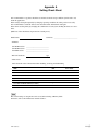
Appendix A
Setting Check Sheet
It is recommended to copy these check sheets and write down the setup conditions (switch and so on)
under the application.
If the setting is changed temporarily by changing operating condition, the setting can be reset easily.
It is recommended to attach the sheets to the unit when check, maintenance and repair.
If the unit is used frequently by changing the combination of each system, making the sheets are convenient.
(Make use of the check sheets in prevention of setting error.)
Model name:
Serial No.: _____________________________
. Firmware
SY1 ROM version: ____________________________
SY2 ROM version: ____________________________
SV ROM version: ____________________________
. RS-232C baud rate:
bps
. Hours meter
Write down the value of hours meter when checking, servicing, and maintaining.
ITEM
Date
H01: OPERATION HOURS
/
H02: DRUM RUNNING HOURS
/
H03: TAPE RUNNING HOURS
/
H04: THREADING COUNTER
/
H12: DRUM RUNNING HOURS (Resettable)
/
H13: TAPE RUNNING HOURS (Resettable)
/
H14: THREADING COUNTER (Resettable)
/
Hours meter
n
The current settings of setup menu can be saved and read using a Memory Stick.
For details, refer to the maintenance manual volume 1.
HDW-1800/D1800
A-1 (E)
Connector panel
Switch
Factory setting
Setting
CH1
HIGH ON
[||]
LOW OFF
[||]
HIGH OFF
[||]
HIGH ON
CH2
HIGH ON
[||]
LOW OFF
[||]
HIGH OFF
[||]
HIGH ON
1
ON
[||]
ON
[||]
OFF
2
ON
[||]
ON
[||]
OFF
Switch
Factory setting
Setting
REMOTE 1 (9P)
LOCAL
[||]
Lighting (REMOTE)
[||]
Lightless (LOCAL)
REMOTE 2 (50P)
LOCAL
[||]
Lighting (REMOTE)
[||]
Lightless (LOCAL)
Switch
Factory setting
Setting
KEY INHIBIT
OFF
[||]
Analog audio input level 600 Z
Reference video input 75 Z
Upper control panel
Switch panel
ON
[||]
OFF
Switches on the board
n
Never change the setting of Factory use switches.
Board
Name
Channel
Switch No.
Factory setting
AE-31
Factory use
(HEAD TUNE switch)
CH1
S100
All OFF
_
CH2
S200
All OFF
_
Audio input, output, and monitor
output headroom
CH1/2/L/R
S1902
20 dB
[||]
20
[||]
18
[||]
16
[||]
12
Audio input reference level
CH1/2
S1902
+4 dBm/600 Z
[||]
+4
[||]
0
[||]
_3
[||]
_20
Audio output reference level
CH1/CH2
S1902
+4 dBm/600 Z
[||]
+4
[||]
0
[||]
_3
[||]
_20
Monitor output reference level
L/R
S1902
+4 dBm/600 Z
[||]
+4
[||]
0
[||]
_3
[||]
_20
Monitor output level
FIXED/VARIABLE switch
L
S2001
Fixed (UNITY)
[||]
Fixed
[||]
Variable
Fixed
[||]
Variable
APR-80
Setting
R
S2000
Fixed (UNITY)
[||]
Factory use
_
S1900
All OFF
_
Factory use
_
S1901
All OFF
_
HPR-21
Factory use
_
S400
All OFF
_
SY-340
Factory use
_
S105
All OFF
_
A-2 (E)
HDW-1800/D1800
(Continued)
Board
Switch No.
: Name
Factory setting
SS-101
S101
1
: TRACKING ENABLE
OFF
2
: Factory use
OFF
3
: DT WOBBLING
OFF
4
: SV ERR DISABLE
OFF
S1501
_
Never change the settings of S1501 switch since each switch is set according to the characteristics of the unit.
OFF
_
2 - 6 : Model ID switch
See below.
_
7
ON
_
1
S1502
Setting
: Factory use
: J/SY
8
: 525/625
OFF
1
: EXTENDED MENU
ON
2
: MAINTENANCE MODE ACCESS ENABLE
ON
3 - 8 : Factory use
OFF
_
S1501 factory setting ( \ : Knob position)
HDW-1800
HDW-D1800
ON
ON
1
HDW-1800/D1800
8
1
8
A-3 (E)
Page
P01 : HOME
P02 : TC
Button
Name
Factory setting
Setting
SDI
[||]
[||]
SG
[||]
EE
[||]
PB
[||]
DISABLE
[||]
ENABLE
TC
[||]
TC
[||]
UB
[||]
CTL
MENU
_
_
TCG SET
_
_
VIDEO IN
_
F3
EDIT
_
_
F4
E.PRESET
_
_
F5
CLR CNT
_
_
F6
PB/EE
EE
F7
CONFI
DISABLE
F8
COUNTER
F9
F10
F1
TCG SRC
INTERNAL
[||]
INTNTERNAL
[||]
EXT LTC
[||]
SDI IN
F2
TCG MODE
PRESET
[||]
PRESET
[||]
RGN : LTC
[||]
RGN : VITC
F3
TCG RUN
REC
[||]
REC
[||]
FREE
F4
DROP FRM
DF
[||]
DF
[||]
NDF
F5
_
F6
_
F7
_
F8
_
F9
_
F10
TCR
AUTO
[||]
LTC
[||]
AUTO
[||]
VITC
VIDEO IN
SDI
[||]
SDI
[||]
SG
F2
REF VID
INPUT
[||]
REF
[||]
INPUT
F3
SYNC PHS
0
VALUE: _______
F4
SYCN FIN
0
VALUE: _______
[||]
VALUE: _______
[||]
8F
P03 : VID PROC F1
F5
V.PROC
LOCAL
[||]
LOCAL
[||]
MENU
F6
VID LEVL
PRESET
[||]
PRESET
[||]
VALUE: _______
CHR LEVL
PRESET
[||]
PRESET
[||]
VALUE: _______
F7
P04 : MISC-1
SDI
F1
F2
F8
*1
HUE/CHR PHAS
PRESET
[||]
PRESET
F9
*2
SETUP LV/BLK LEVL PRESET
[||]
PRESET
[||]
VALUE: _______
F10
PRESET
_
_
F1
CAPSTAN
4F
[||]
2F
[||]
4F
F2
_
F3
PREREAD
OFF
[||]
ON
[||]
OFF
F4
_
F5
CHARA
ON
[||]
ON
[||]
OFF
F6
T-INFO
TOTAL
[||]
TOTAL
[||]
REMAIN
F7
_
F8
_
F9
_
F10
_
*1: HUE (59.94i, 29.97PsF mode) /CHR PHAS (50i, 25PsF, 23.98PsF, 24PsF mode)
*2: SETUP LV (59.94i, 29.97PsF mode) /BLK LEVL (50i, 25PsF, 23.98PsF, 24PsF mode)
A-4 (E)
HDW-1800/D1800
Page
P05 : MISC-2
P06 : EDIT
Button
Factory setting
Setting
F1
_
F2
UMID
_
_
F3
SHOT MRK
_
_
F4
STP CODE
_
_
F5
_
F6
_
F7
_
F8
FREEZE
_
_
F9
FRZOFF
_
_
F10
_
F1
AUTOEDIT
_
_
F2
PREVIEW
_
_
F3
REVIEW
_
_
F4
DMC
_
_
F5
PREROLL
_
_
F6
R/P SEL
OFF
[||]
F7
AUD IN
_
_
F8
AUD OUT
_
_
F9
IN
_
_
F10
OUT
_
_
REC INHI
OFF
[||]
F2
INS TC
_
_
F3
INS CUE
_
_
F4
EDIT
_
_
F5
ASSEMBLE
_
_
F6
INS VID
_
_
F7
INS A1
_
_
F8
INS A2
_
_
F9
INS A3
_
_
F10
INS A4
_
_
P07 : E.PRESET F1
HDW-1800/D1800
Name
OFF
[||]
RECDER
ON
[||]
OFF
[||]
PLAYER
A-5 (E)
Page
P08 : AUD INP
Button
Name
F1
EMPHASIS
Factory setting
Setting
OFF
[||]
F2 *3
AUD MIX
(→P102)
_
_
ON
[||]
OFF
F3 *4
AUD MONI
(→P100)
_
_
F4
MT.SCALE
FULL
[||]
FULL
[||]
FINE
F5
_
F6
AUDIO SG
OFF
[||]
OFF
[||]
ON
F7
INP A1
ANA-1
[||]
SDI-1
[||]
AES-1
[||]
ANA-1
F8
INP A2
ANA-2
[||]
SDI-2
[||]
AES-2
[||]
ANA-2
F9
INP A3
ANA-1
[||]
SDI-3
[||]
AES-3
[||]
ANA-1
F10
INP A4
ANA-2
[||]
SDI-4
[||]
AES-4
[||]
ANA-2
*3: When F2 (AUD MIX) in the function menu page P08 : AUD INP is selected, P102 : AUD MIX is displayed to allow audio mixing setting.
n
Audio mixing setting for the CUE track is available with the setup menu ITEM-833 (CUE AUDIO INPUT SELECT).
Page
Recording track
Factory setting
Setting
P102 : AUD MIX
CH-1
NOT MIX
[||]
NOT MIX
[||]
MIX [[||] CH-1 [||] CH-2 [||] CH-3 [||] CH-4]
CH-2
NOT MIX
[||]
NOT MIX
[||]
MIX [[||] CH-1 [||] CH-2 [||] CH-3 [||] CH-4]
CH-3
NOT MIX
[||]
NOT MIX
[||]
MIX [[||] CH-1 [||] CH-2 [||] CH-3 [||] CH-4]
CH-4
NOT MIX
[||]
NOT MIX
[||]
MIX [[||] CH-1 [||] CH-2 [||] CH-3 [||] CH-4]
*4: When F3 (AUD MONI) in the function menu page P08 : AUD INP is selected, P100 : AUD MONI is displayed to allow audio monitor setting.
n
F5 (TRCK CHG) of the function menu page P100 : AUD MONI is displayed only during playback of MPEG IMX to allow selective setting (CH-5 to CH-8).
Page
Channel monitored
Factory setting
Setting
P100 : AUD MONI
or
P101 : AUD MONI
L
CH-1 only
[||]
CH-1
CH-5
[||] CUE
[||]
[||]
[||]
[||]
[||]
[||]
[||]
R
A-6 (E)
CH-1 only
CH-1
CH-5
[||] CUE
CH-2
CH-6
[||]
CH-2
CH-6
[||]
[||]
[||]
CH-3
CH-7
[||]
CH-3
CH-7
[||]
[||]
[||]
CH-4
CH-8
CH-4
CH-8
HDW-1800/D1800
The material contained in this manual consists of
information that is the property of Sony Corporation.
Sony Corporation expressly prohibits the duplication of
any portion of this manual or the use thereof for any
purpose other than the operation or maintenance of the
equipment described in this manual without the express
written permission of Sony Corporation.
Le matériel contenu dans ce manuel consiste en
informations qui sont la propriété de Sony Corporation.
Sony Corporation interdit formellement la copie de
quelque partie que ce soit de ce manuel ou son emploi
pour tout autre but que des opérations ou entretiens de
l’équipement à moins d’une permission écrite de Sony
Corporation.
Das in dieser Anleitung enthaltene Material besteht aus
Informationen, die Eigentum der Sony Corporation sind.
Die Sony Corporation untersagt ausdrücklich die
Vervielfältigung jeglicher Teile dieser Anleitung oder den
Gebrauch derselben für irgendeinen anderen Zweck als
die Bedienung oder Wartung der in dieser Anleitung
beschriebenen
Ausrüstung
ohne
ausdrückliche
schriftliche Erlaubnis der Sony Corporation.
HDW-1800/D1800
HDW-1800 (SY)
HDW-1800 (CN)
HDW-D1800 (SY)
HDW-D1800 (CN) J, E
3-992-809-01
Sony Corporation
Printed in Japan
2006. 9 08
©2006