1
PROFESSIONAL DISC RECORDER
PDW-1500
OPERATION MANUAL [English]
1st Edition (Revised 6)
Important Safety Instructions
•
•
•
•
•
•
•
•
•
•
•
•
Read these instructions.
Keep these instructions.
Heed all warnings.
Follow all instructions.
Do not use this apparatus near water.
Clean only with dry cloth.
Do not block any ventilation openings.
Install in accordance with the manufacturer’s instructions.
Do not install near any heat sources such as radiators, heat
registers, stoves, or other apparatus (including amplifiers)
that produce heat.
Do not defeat the safety purpose of the polarized or
grounding-type plug. A polarized plug has two blades with
one wider than the other. A grounding-type plug has two
blades and a third grounding prong. The wide blade or the
third prong are provided for your safety. If the provided plug
dose not fit into your outlet, consult an electrician for
replacement of the obsolete outlet.
Protect the power cord from being walked on or pinched
particularly at plugs, convenience receptacles, and the point
where they exit from the apparatus.
Only use attachments/accessories specified by the
manufacturer.
Use only with the cart, stand, tripod, bracket, or table
specified by the manufacturer, or sold with the apparatus.
When a cart is used, use caution when moving the cart/
apparatus combination to avoid injury from tip-over.
• Unplug this apparatus during lightning storms or when
unused for long periods of time.
• Refer all servicing to qualified service personnel. Servicing
is required when the apparatus has been damaged in any
way, such as power-supply cord or plug is damaged, liquid
has been spilled or objects have fallen into the apparatus,
the apparatus has been exposed to rain or moisture, does
not operate normally, or has been dropped.
WARNING
To reduce the risk of fire or electric shock,
do not expose this apparatus to rain or
moisture.
To avoid electrical shock, do not open the
cabinet. Refer servicing to qualified
personnel only.
THIS APPARATUS MUST BE EARTHED.
CAUTION
The apparatus shall not be exposed to dripping or splashing.
No objects filled with liquids, such as vases, shall be placed on
the apparatus.
The unit is not disconnected from the AC power source
(mains) as long as it is connected to the wall outlet, even if the
unit itself has been turned off.
2
Do not install the appliance in a confined space, such as a
book case or built-in cabinet.
This apparatus is provided with a main switch on the rear
panel. Install this apparatus so that user can access the main
switch easily.
This symbol is intended to alert the user to
the presence of uninsulated “dangerous
voltage” within the product’s enclosure that
may be of sufficient magnitude to constitute
a risk of electric shock to persons.
This symbol is intended to alert the user to
the presence of important operating and
maintenance (servicing) instructions in the
literature accompanying the appliance.
WARNING: THIS WARNING IS APPLICABLE FOR USA
ONLY.
If used in USA, use the UL LISTED power cord specified
below.
DO NOT USE ANY OTHER POWER CORD.
Plug Cap
Cord
Length
Rating
Parallel blade with ground pin
(NEMA 5-15P Configuration)
Type SJT, three 16 or 18 AWG wires
Minimum 1.5 m (4 ft. 11 in.), Less than
2.5 m (8 ft. 3 in.)
Minimum 10 A, 125 V
Using this unit at a voltage other than 120 V may require the
use of a different line cord or attachment plug, or both. To
reduce the risk of fire or electric shock, refer servicing to
qualified service personnel.
WARNING: THIS WARNING IS APPLICABLE FOR OTHER
COUNTRIES.
1. Use the approved Power Cord (3-core mains lead)/
Appliance Connector/Plug with earthing-contacts that
conforms to the safety regulations of each country if
applicable.
2. Use the Power Cord (3-core mains lead)/Appliance
Connector/Plug conforming to the proper ratings (Voltage,
Ampere).
If you have questions on the use of the above Power Cord/
Appliance Connector/Plug, please consult a qualified service
personnel.
CAUTION
The use of optical instruments with this product will increase
eye hazard.
Use of controls or adjustments or performance of procedures
other than those specified herein may result in hazardous
radiation exposure.
This Professional Disc Recorder is classified as a CLASS 1
LASER PRODUCT.
Laser diode properties
Wavelength: 403 to 410 nm
Emission duration: Continuous
Laser output power: 65 mW (max. of pulse peak), 35 mW
(max. of CW)
Standard: IEC60825-1 (2001)
Tekniska data för laserdiod
Våglängd: 403 till 410 nm
Emissionslängd: Kontinuerlig
Laseruteffekt: 65 mW (max. för pulstopp), 35 mW (max. för
kontinuerlig våg)
Standard: IEC60825-1 (2001)
Egenskaber for laserdiode
Bølgelængde: 403 til 410 nm
Strålingsvarighed: Kontinuerlig
Afgivet lasereffekt: 65 mW (maks stråletoppunkt), 35 mW
(maks ved kontinuerlig stråling)
Standard: IEC60825-1 (2001)
Laserdiodin ominaisuudet
Aallonpituus: 403 - 410 nm
Säteilyn kesto: jatkuva
Laserin teho: 65 mW (pulssin huipun maks.), 35 mW
(jatkuvan aallon maks.)
Standardi: IEC60825-1 (2001)
WARNING
Excessive sound pressure from earphones and headphones
can cause hearing loss.
In order to use this product safely, avoid prolonged listening at
excessive sound pressure levels.
VAROITUS!
LAITTEEN KÄYTTÄMINEN MUULLA KUIN TÄSSÄ
KÄYTTÖOHJEESSA MAINITULLA TAVALLA SAATTAA
ALTISTAA KÄYTTÄJÄN TURVALLISUUSLUOKAN 1
YLITTÄVÄLLE NÄKYMÄTTÖMÄLLE LASERSÄTEILYLLE.
VARNING
OM APPARATEN ANVÄNDS PÅ ANNAT SÄTT ÄN I DENNA
BRUKSANVISNING SPECIFICERATS, KAN ANVÄNDAREN
UTSÄTTAS FÖR OSYNLIG LASERSTRÅLNING, SOM
ÖVERSKRIDER GRÄNSEN FÖR LASERKLASS 1.
For the customers in the USA
This equipment has been tested and found to comply with the
limits for a Class A digital device, pursuant to Part 15 of the
FCC Rules. These limits are designed to provide reasonable
protection against harmful interference when the equipment is
operated in a commercial environment. This equipment
generates, uses, and can radiate radio frequency energy and,
if not installed and used in accordance with the instruction
manual, may cause harmful interference to radio
communications. Operation of this equipment in a residential
area is likely to cause harmful interference in which case the
user will be required to correct the interference at his own
expense.
You are cautioned that any changes or modifications not
expressly approved in this manual could void your authority to
operate this equipment.
All interface cables used to connect peripherals must be
shielded in order to comply with the limits for a digital device
pursuant to Subpart B of Part 15 of FCC Rules.
For the State of California, USA only
Perchlorate Material - special handling may apply, See
www.dtsc.ca.gov/hazardouswaste/perchlorate
Perchlorate Material : Lithium battery contains perchlorate.
This label is located on the top panel of the drive unit.
Denna etikett finns på ovansidan av driftenheten.
Denne mærkat sidder på drevenhedens øverste panel.
Tämä kyltti sijaitsee ajurilaitteen yläpinnalla.
For the customers in Europe
This product with the CE marking complies with both the EMC
Directive and the Low Voltage Directive issued by the
Commission of the European Community.
Compliance with these directives implies conformity to the
following European standards:
• EN60065: Product Safety
• EN55103-1: Electromagnetic Interference (Emission)
• EN55103-2: Electromagnetic Susceptibility (Immunity)
This product is intended for use in the following
Electromagnetic Environment(s):
Dette merket er plassert på oversiden av driverenheten.
3
E1 (residential), E2 (commercial and light industrial), E3
(urban outdoors) and E4 (controlled EMC environment, ex. TV
studio).
For the customers in Europe
The manufacturer of this product is Sony Corporation, 1-7-1
Konan, Minato-ku, Tokyo, Japan.
The Authorized Representative for EMC and product safety is
Sony Deutschland GmbH, Hedelfinger Strasse 61, 70327
Stuttgart, Germany. For any service or guarantee matters
please refer to the addresses given in separate service or
guarantee documents.
For the Customers in Taiwan only
4
Table of Contents
Before Using the Unit .............................. 7
Setting the Line Mode ................................7
Chapter 1 Overview
1-1 Features ............................................... 9
1-2 MPEG-4 Visual Patent Portfolio License
........................................................... 11
1-3 MPEG-2 Video Patent Portfolio License
........................................................... 11
Chapter 2 Names and Functions of
Parts
2-1 Front Panel ........................................ 12
2-2 Rear Panel ......................................... 20
Chapter 3 Preparations
3-1 Connections and Settings................ 23
3-1-1 Connecting an External Monitor ..... 23
3-1-2 Connections for Using PDZ-1 Proxy
Browsing Software ..........................24
3-1-3 Connecting to a Nonlinear Editing
System..............................................26
3-1-4 Connections for Cut Editing ............ 27
3-1-5 Connections for Clip Audio Insert
Editing..............................................29
3-1-6 Editing Control Unit Settings .......... 33
3-2 Setup .................................................. 34
3-3 Setting the Date and Time................ 34
3-4 Superimposed Text Information...... 35
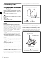
3-5 Handling Discs .................................. 38
3-5-1 Discs Used for Recording and Playback
.........................................................38
3-5-2 Notes on Handling ........................... 38
3-5-3 Write-Protecting Discs ....................38
3-5-4 Loading and Unloading a Disc ........ 38
3-5-5 Formatting a Disc ............................39
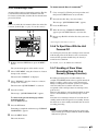
3-5-6 To Eject Discs With the Unit Powered
Off....................................................39
3-5-7 Handling of Discs When Recording
Does Not End Normally (Salvage
Function)..........................................39
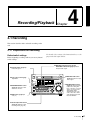
Chapter 4 Recording/Playback
4-1 Recording .......................................... 41
4-1-1 Preparations for Recording ..............41
4-1-2 Recording Time Code and User Bit
Values ..............................................43
4-1-3 Recording Operation........................46
4-1-4 Auto Clip List Recording for Automatic
Inclusion of Recorded Clips in Clip Lists
..........................................................47
4-2 Playback ............................................ 48
4-2-1 Preparations for Playback ................48
4-2-2 Playback Operation..........................49
4-2-3 Thumbnail Search ............................50
4-2-4 Clip List Playback............................52
4-2-5 Repeat Playback...............................53
4-2-6 Locking and Deleting Clips ............. 54
Chapter 5 Scene Selection
5-1 Overview ............................................ 56
5-2 Creating Clip Lists ............................ 59
5-2-1 Selecting Clips .................................59
5-2-2 Reordering Sub Clips.......................61
5-2-3 Trimming Sub Clips ........................63
5-2-4 Deleting Sub Clips ...........................64
5-2-5 Previewing the Current Clip List..... 64
5-2-6 Saving the Current Clip List to Disc64
5-3 Managing Clip Lists (CLIP Menu) .... 66
5-3-1 Loading a Clip List From Disc Into Unit
Memory............................................66
5-3-2 Deleting Clip Lists From a Disc ...... 67
5-3-3 Clearing the Current Clip List From the
Unit Memory....................................67
5-3-4 Presetting the Initial Time Code of the
Current Clip List ..............................67
5-3-5 Sorting Clip Lists .............................68
5-4 Using PDZ-1 Proxy Browsing Software
........................................................... 69
Chapter 6 Insert Editing
6-1 Clip Audio Insert Editing .................. 70
6-1-1 Preparations for Editing................... 70
6-1-2 Editing Operations ...........................71
Table of Contents
5
Chapter 7 File Operations
Appendixes
7-1 Overview ............................................ 73
7-1-1 Directory Structure ..........................73
7-1-2 File Operation Restrictions ..............74
7-1-3 Assigning User-Defined Clip Titles 76
7-1-4 Assigning User-Defined Clip and Clip
List Names ....................................... 77
7-2 File Access Mode File Operations (for
Windows) .......................................... 79
7-2-1 Making FAM Connections ..............80
7-2-2 Operating on Files ...........................80
7-2-3 Exiting File Operations.................... 80
7-3 File Operations in File Access Mode (for
Macintosh) ........................................ 81
7-3-1 Making FAM Connections ..............81
7-3-2 Operating on Files ...........................82
7-3-3 Exiting File Operations.................... 82
7-4 FTP File Operations .......................... 83
7-4-1 Making FTP Connections ................83
7-4-2 Command List .................................84
7-5 Recording Continuous Time Code With
FAM and FTP Connections.............. 90
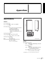
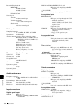
Specifications........................................ 133
Glossary................................................. 136
Chapter 8 Menus
8-1 Menu System Configuration ............ 91
8-2 Basic Setup Menu ............................. 92
8-2-1 Items in the Basic Setup Menu ........ 92
8-2-2 Basic Menu Operations ...................95
8-3 Extended Menu ................................. 99
8-3-1 Items in the Extended Menu ............99
8-3-2 Extended Menu Operations ...........110
8-3-3 Using UMID Data .........................111
8-4 Maintenance Menu.......................... 114
8-4-1 Items in the Maintenance Menu .... 114
8-4-2 Maintenance Menu Operations...... 116
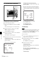
8-5 System Menu................................... 119
8-5-1 Items in the System Menu .............119
8-5-2 System Menu Operations...............120
Chapter 9 Maintenance and
Troubleshooting
9-1 Periodic Maintenance ..................... 122
9-1-1 Digital Hours Meter....................... 122
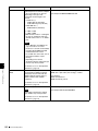
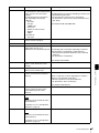
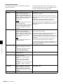
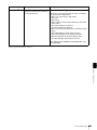
9-2 Error Messages ............................... 123
9-3 Alarms.............................................. 124
9-3-1 Alarm List......................................124
6
Table of Contents
Index....................................................... 138
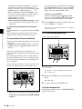
Before Using the Unit
3
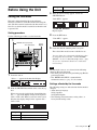
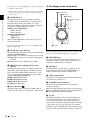
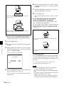
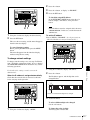
Setting the Line Mode
Setting
Line mode
625
625: PAL
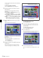
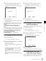
When the desired setting appears, release the
SHUTTLE button.
“Push SET !!” appears.
This unit is shipped with the line mode still unset.
Therefore you need to set the line mode before using the
unit. (The unit cannot be used unless the line mode is set.)
Once it is set, the line mode is retained even when the unit
is powered off.
Setting procedure
Use the following procedure to set the line mode.
To redo the selection
Repeat step 2.
4
Press the SET button.
“Turn OFF !!” appears.
1
POWER switch (rear panel)
2,3
Time data display
5
EJECT
ACCESS
NETWORK
LOCAL
REMOTE
MONITOR
L
MIX
R
SG DATA
ANA SDI
AE8/EBU
dB OVER
0
SG DATA
ANA SDI
AE8/EBU
dB OVER
0
SG DATA
ANA SDI
AE8/EBU
dB OVER
0
SG DATA
ANA SDI
AE8/EBU
dB OVER
0
-12
-12
-12
-12
-20
-20
-20
-20
-30
-40
-30
-40
-30
-40
-30
-40
-60
CH-
-60
15
-60
26
ALL/CH-1
37
CH-
MINUTES
MONITOR
1/2 3/4
AUDIO
18 24 BIT
5/6 7/8 4 8 CH
48
INPUT SEL
CH-2
VIDEO
INPUT SEL
CH-3
625
525
COUNTER
SELECT
CH-4
STOP
KEY INH ALARM
REC INH
SECONDS
HOLD
SUB
CLIP
SYS MENU
MENU
THUMB
NAIL
F REV
F FWD
UT T
LE
JO G
VAR
ESSENCE
MARK
SHIFT
SET RESET
S.SEL
MARK1
REC
IN
TOP
SH
FRAMES
IMX[50 40 30]
DVCAM
CLIP
MENU
NEXT
PLAY
PREV
HOURS
-60
CH-
AUDIO
MONITOR SEL METER SEL INPUT CH
VARIABLE
REC
PRESET
PB
PHONES
CH-
EDIT REMOTE [9P iLINK]
VITC VIUB COUNTER VITC
INPUT
i.LINK
SDI
CMPST
Y-R,B
SG
OUT
END
MARK2
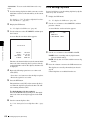
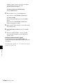
Power the unit off, and then power it on again.
The selected line mode becomes available for use.
You can change the setting made with this procedure
by using basic menu item 013 “525/625 SYSTEM
SELECT.” See 8-2-2 “Basic Menu Operations” (page
95) for more information about how to make basic
menu settings.
Note
5
1
4
Power the unit on.
“Select ----” appears in the time data display.
The line mode is not set, or is cleared, in the following
situations. Reset the line mode.
• The unit is powered off before performing step 4 in the
previous procedure.
• The “RESET ALL SETUP” command in the
maintenance menu (see page 114) is executed.
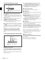
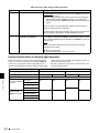
Settings affected by the line mode
2
With the SHUTTLE button held down, rotate the jog
dial.
When you rotate the jog dial in the forward direction,
the “----” part of the display changes in the sequence
525U > 525J > 625. When you rotate it in the reverse
direction, the display changes in the sequence 625 >
525J > 525U.
Setting
Line mode
525U
525(U): NTSC (areas outside Japan)
525J
525(J): NTSC (Japan)
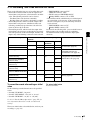
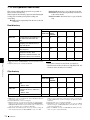
The following settings are affected when the line mode is
changed.
• Alarm message language
525(J): Japanese
525(U)/625: English
• The following menu item names, setting values, or
factory default setting values
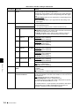
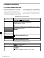
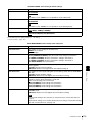
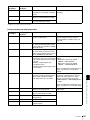
Before Using the Unit
7
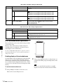
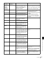
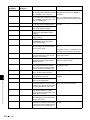
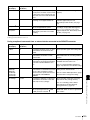
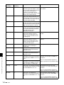
Item
No.
Item name
Settings a)
525 (U)/525 (J) 625
Basic menu
002
CHARACTER H- 00 to 0A to 2A
POSITION
00 to 09 to 29
003
CHARACTER V- 00 to 2E to 38
POSITION
00 to 37 to 43
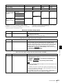
Extended menu
601
VITC POSITION 12H to 16H to
SEL-1
20H
9H to 19H to
22H
602
VITC POSITION 12H to 18H to
20H
SEL-2
9H to 21H to
22H
628
DF MODE
No item
652
UMID SDI VANC 12 H to 17 H to 9 H to 17 H to
19 H
18 H
LINE
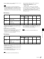
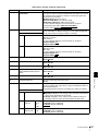
660
ESSENCE
MARK SDI
VANC LINE
12 H to 17 H to 9 H to 17 H to
19 H
18 H
703
BLANK LINE
SELECT
Setting range:
ALL LINE,
LINE 12 to
LINE 20
(525(U))/LINE
12 to LINE 21
(525(J))
Setting range:
ALL LINE,
LINE 9, 322 to
LINE 22, 335,
LINE 23
710
INTERNAL
VIDEO SIGNAL
GENERATOR
BB, CB75,
CB100
BB, CB75,
CB100
713
VIDEO SETUP
REFERENCE
Item
No item
718
SETUP LEVEL/
BLACK LEVEL
SETUP LEVEL BLACK LEVEL
723
INPUT VIDEO
BLANK
Setting range:
ALL LINE,
LINE 12 to
LINE 20
Item
a) Underlined values are the factory defaults.
8
Before Using the Unit
Setting range:
ALL LINE,
LINE 9, 322 to
LINE 22, 335
Overview
1-1 Features
The PDW-1500 Professional Disc Recorder is a half-rack
sized recorder optimized for use with nonlinear editing
systems. Despite its compact size, this unit offers highspeed data transfers between compatible nonlinear
devices, creating a powerful editing tool for video
productions.
The features of the PDW-1500 include the following.
MPEG IMX/DVCAM recording
Chapter
1
times speed for MPEG IMX signals. For low-resolution
proxy AV data, a transfer speed of up to 50 times faster
than real time is achieved.
Thumbnail search operation
Simply press the THUMBNAIL button and the PDW1500 instantly displays thumbnails on a connected
monitor. You can easily cue up the desired scene by
guiding the cursor to the corresponding thumbnail and
confirming your selection with the SET button.
Scene selection
The PDW-1500 offers the capability to record and play
back both MPEG IMX 1) and DVCAM 1) streams. Users
have the flexibility to select from these formats according
to their picture-quality needs, or to match their editingformat requirements.
You can create and play back clip lists of selected clips
from the disc, arranged in any order.
One disc can store up to 99 clip lists.
Clip lists make it simple to perform offline editing in the
field for later use with full-scale nonlinear editing systems
(XPRI 1), etc.).
1) MPEG IMX and DVCAM are trademarks of Sony Corporation.
1) XPRI is a trademark of Sony Corporation.
Proxy AV data
Clip audio insert editing
Proxy AV data is a low-resolution, MPEG-4 based version
of a full-resolution MPEG IMX/DVCAM stream (a video
bandwidth of 1.5 Mbps and an audio bandwidth of 64 kbps
per channel). Whenever a recording is made, the unit
automatically generates proxy AV data from the fullresolution data and records it on the Professional Disc.
Proxy AV data is much smaller in size than the fullresolution IMX or DVCAM data. It can be transferred
quickly over computer networks, easily edited in the field
with laptop computers, and readily used in a wide variety
of applications, such as content management on smallscale servers.
You can perform insert editing on the audio tracks of a
recorded clip, in the same way that you edit conventional
VTR clips. You can also mix audio signals recorded on the
disc with input audio.
Quick picture search by jog and shuttle
dials
The PDW-1500 has jog and shuttle dials as a conventional
VTR to search picture in a clip. The jog dial is for frameby-frame search at –1 to +1 times normal speed and the
shuttle dial is for high-speed search at ±35 times normal
speed.
High-speed file transfer
The PDW-1500 has two optical heads enabling high-speed
file transfer. For high-resolution (MPEG IMX and
DVCAM) material, the maximum transfer speed is at
about 5-times speed for DVCAM signals and about 2.5-
IT-friendly system
In the PDW-1500, clips are recorded as video and audio
data files 1). This file-based recording system also allows
material to be viewed directly on a computer linked to the
1-1 Features
9
Chapter 1 Overview
unit via an i.LINK 2) (file access mode, called FAM below)
connection—in the same way that a computer reads data
files on an external drive. The interfaces include the
S400 (i.LINK) connector, supporting AV/C (Audio/
Video Control) and i.LINK (FAM) protocols, and
(network) connector. The
(network) connector
supports MXF (Material eXchange Format) file transfer
capability to exchange contents with other equipment
supporting MXF.
1) A clip is created every time recording is stopped.
• Video and audio data are always recorded in empty sections of the disc.
Recording begins instantly, even after playback, without overwriting
existing video on the disc.
• Recording is done in clip units, which makes it simple to delete a clip
immediately after shooting if it is judged to be unneeded.
• During playback, thumbnail lists make it easy to identify clips. The
random access nature of the media allows the NEXT and PREV buttons
to jump instantly to clip start frames, making it easy to check the video
and audio in the clips.
• i.LINK (FAM) or network connections make it possible to transfer clip
files at high speed between this unit and remote computers.
2) i.LINK is a trademark of Sony Corporation.
Flexible metadata recording
XDCAM 1) can record various types of metadata together
with video and audio data, such as the date and time of
shooting, the cameraman, the recording method, and
comments about the material. This metadata can be used in
applications such as the following.
• The supplied PDZ-1 Proxy Browsing Software can be
used to add titles, comments, and other text data to discs
and clips.
• Computer-readable text files can be recorded on the
Professional Disc, to allow systematic content
management.
• The ability to search metadata for the required audio and
video scenes brings greater efficiency to various stages
of the video production process (editing, archiving, etc.).
1) XDCAM is a trademark of Sony Corporation.
Supports a variety of interfaces
The PDW-1500 supports a variety of interfaces and is
suitable for use with various nonlinear editing systems.
Analog interfaces
Video: The unit can input and output a composite analog
video signal.
Audio: The unit has two audio channels. When in 4channel mode, you can input two channels of audio
either as channels 1 and 2 or as channels 3 and 4. The
two audio channels can be output also either as
channels 1 and 2 or as channels 3 and 4.
Digital interfaces
SDI (Serial Digital Interface)/AES/EBU: This allows
the unit to input and output D1 (component) format
digital video and audio signals and also AES/EBUformat digital audio signals.
10
1-1 Features
Equipped with i.LINK connector
The i.LINK connector of this unit supports the following
two functions.
Input and output of DV streams (AV/C mode)
• DV streams can be output from this unit and recorded on
standard DV equipment.
• During MPEG IMX playback, the playback signals can
be converted and output as DV streams, allowing you to
connect DV-compatible nonlinear editors.
• The output from external DV devices (VTRs, nonlinear
editors, etc.) can be input to this unit and recorded on
Professional Discs.
Computer access to files (file access mode)
Use of application software which supports the XDCAM
series 1) enables random access to video, audio, and
metadata files on Professional Discs, with the ability to
display file lists and perform file-based reads and
overwrites.
Files can be transferred at high speed, and thumbnail lists
of disc contents can be viewed on computer screens.
1) Such software includes the supplied PDZ-1 Proxy Browsing Software and
the XPRI series.
Equipped with network connector
This network connector of unit can be connected to
computers and networks to enable high-speed file transfers
and display of lists of the video, audio, and metadata files
stored on Professional Discs. Workflows can be improved
by the ability to use FTP commands to transfer files to
remote locations.
Supporting SNMP for service and
maintenance
The PDW-1500 is compatible with Sony remote
maintenance and monitoring software—an SNMPcompliant application that can monitor and log the
hardware’s status in real time via a TCP/IP network. If a
malfunction is detected, this system can immediately
identify the problem, allowing you to take corrective
action.
1-3 MPEG-2 Video Patent
Portfolio License
THIS PRODUCT IS LICENSED UNDER THE MPEG-4
VISUAL PATENT PORTFOLIO LICENSE FOR THE
PERSONAL AND NON-COMMERCIAL USE OF A
CONSUMER FOR
ANY USE OF THIS PRODUCT OTHER THAN
CONSUMER PERSONAL USE IN ANY MANNER
THAT COMPLIES WITH THE MPEG-2 STANDARD
FOR ENCODING VIDEO INFORMATION FOR
PACKAGED MEDIA IS EXPRESSLY PROHIBITED
WITHOUT A LICENSE UNDER APPLICABLE
PATENTS IN THE MPEG-2 PATENT PORTFOLIO,
WHICH LICENSE IS AVAILABLE FROM MPEG LA,
L.L.C., 250 STEELE STREET, SUITE 300, DENVER,
COLORADO 80206.
(i) ENCODING VIDEO IN COMPLIANCE WITH THE
MPEG-4 VISUAL STANDARD (“MPEG-4 VIDEO”)
AND/OR
(ii)DECODING MPEG-4 VIDEO THAT WAS
ENCODED BY A CONSUMER ENGAGED IN A
PERSONAL AND NON-COMMERCIAL
ACTIVITY AND/OR WAS OBTAINED FROM A
VIDEO PROVIDER LICENSED BY MPEG LA TO
PROVIDE MPEG-4 VIDEO.
NO LICENSE IS GRANTED OR SHALL BE IMPLIED
FOR ANY OTHER USE. ADDITIONAL
INFORMATION INCLUDING THAT RELATING TO
PROMOTIONAL, INTERNAL AND COMMERCIAL
USES AND LICENSING MAY BE OBTAINED FROM
MPEG LA, LLC. SEE HTTP://WWW.MPEGLA.COM
Chapter 1 Overview
1-2 MPEG-4 Visual Patent
Portfolio License
“PACKAGED MEDIA” means any storage media storing
MPEG-2 video information such as DVD movie which are
sold/distributed to general consumers. Disc replicators or
sellers of the PACKAGED MEDIA need to obtain licenses
for their own business from MPEG LA. Please contact
MPEG LA for any further information. MPEG LA. L.L.C.,
250 STEELE STREET, SUITE 300, DENVER,
COLORADO 80206
http://www.mpegla.com
MPEG LA is offering licenses for (i) manufacturing/sales
of any storage media storing MPEG-4 Visual video
information (ii) distribution/broadcasting of MPEG-4
Visual video information in any manner (such as online
video distribution service, internet broadcasting, TV
broadcasting). Other usage of this product may be
required to obtain license from MPEGLA. Please contact
MPEG LA for any further information. MPEG LA, L.L.C.,
250 STEELE STREET, SUITE 300, DENVER,
COLORADO 80206, http://www.mpegla.com
1-2 MPEG-4 Visual Patent Portfolio License / 1-3 MPEG-2 Video Patent Portfolio License
11
Names and Functions of
Parts
Chapter
2
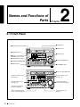
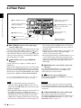
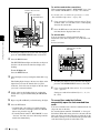
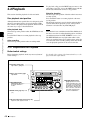
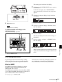
2-1 Front Panel
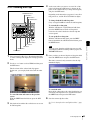
7 HOLD button
1 On/standby switch and indicator
EJECT
8 MENU button
2 ACCESS indicator
ACCESS
3 Remote control switch and
NETWORK access indicator
NETWORK
LOCAL
REMOTE
MONITOR
L
MIX
R
SG DATA
ANA SDI
AE8/EBU
dB OVER
0
SG DATA
ANA SDI
AE8/EBU
dB OVER
0
SG DATA
ANA SDI
AE8/EBU
dB OVER
0
-12
-12
-12
-20
-20
-20
-20
-30
-40
-30
-40
-30
-40
-30
-40
-60
-60
15
CH-
CH-
-60
26
CH-
VARIABLE
REC
PRESET
PB
PHONES
ALL/CH-1
EDIT REMOTE [9P iLINK]
VITC VIUB COUNTER VITC
INPUT
i.LINK
SDI
CMPST
Y-R,B
SG
HOURS
CH-
MINUTES
MONITOR
1/2 3/4
AUDIO
5/6 7/8 4 8 CH
18 24 BIT
-60
37
AUDIO
MONITOR SEL METER SEL INPUT CH
4 VIDEO INPUT SEL button
5 COUNTER SELECT button
SG DATA
ANA SDI
AE8/EBU
dB OVER
0
-12
48
INPUT SEL
CH-2
VIDEO
INPUT SEL
CH-3
KEY INH ALARM
REC INH
SECONDS
625
525
COUNTER
SELECT
SYS MENU
MENU
SUB
CLIP
THUMB
NAIL
JO G
VAR
9 SHIFT button
CLIP
MENU
ESSENCE
MARK
SHIFT
SET RESET
S.SEL
MARK1
REC
STOP
IN
6 SUBCLIP button
LE
0 SET and RESET buttons
NEXT
PLAY
PREV
F REV
TOP
U TT
IMX[50 40 30]
DVCAM
HOLD
CH-4
SH
FRAMES
F FWD
OUT
END
qa THUMBNAIL button
MARK2
EJECT
qs Disc slot and EJECT button
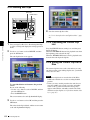
1 Audio level meter section
(see page 14)
ACCESS
NETWORK
LOCAL
REMOTE
MONITOR
L
MIX
R
2 Audio settings section
(see page 15)
SG DATA
ANA SDI
AE8/EBU
dB OVER
0
SG DATA
ANA SDI
AE8/EBU
dB OVER
0
SG DATA
ANA SDI
AE8/EBU
dB OVER
0
SG DATA
ANA SDI
AE8/EBU
dB OVER
0
-12
-12
-12
-12
-20
-20
-20
-20
-30
-40
-30
-40
-30
-40
-30
-40
-60
CH-
-60
15
VARIABLE
REC
PRESET
PB
PHONES
CH-
-60
26
CH-
ALL/CH-1
CH-
MINUTES
MONITOR
1/2 3/4
AUDIO
5/6 7/8 4 8 CH
18 24 BIT
48
INPUT SEL
CH-2
VIDEO
INPUT SEL
CH-3
NEXT
PLAY
PREV
HOURS
-60
37
AUDIO
MONITOR SEL METER SEL INPUT CH
EDIT REMOTE [9P iLINK]
VITC VIUB COUNTER VITC
INPUT
i.LINK
SDI
CMPST
Y-R,B
SG
CH-4
STOP
SECONDS
625
525
COUNTER
SELECT
3 Audio level adjustment
section (see page 16)
4 Recording and playback
control section (see page 16)
12
2-1 Front Panel
F REV
F FWD
SH
FRAMES
U TT
LE
JO G
VAR
(see page 17)
IMX[50 40 30]
DVCAM
HOLD
SYS MENU
MENU
SUB
CLIP
THUMB
NAIL
CLIP
MENU
ESSENCE
MARK
SHIFT
SET RESET
S.SEL
MARK1
REC
IN
TOP
5 Status display section
KEY INH ALARM
REC INH
6 Shuttle/jog/variable
control block (see page 18)
OUT
END
MARK2
7 Arrow buttons (see
page 19)
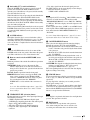
a On/standby (^ /1) switch and indicator
When the POWER switch on the rear panel is in the ^
position, this switches the PDW-1500 between the
operating state (the indicator is lit green) and the standby
state (the indicator is lit red).
When the indicator is lit red, pressing the switch makes the
indicator flash green. When the PDW-1500 is in the
operating state, the indicator lights continuously green.
When the indicator is lit green, pressing the switch makes
the indicator flash. When the PDW-1500 is in the standby
state, the indicator lights red.
When using the PDW-1500, normally leave the rear panel
POWER switch in the ^ (on) position, and use this switch
to switch the PDW-1500 between the operating state and
standby state.
• Test video signal from the internal signal generator
The INPUT display in the status display section changes,
to reflect the selection, as follows:
i.LINKtSDItCMPSTtSG
b ACCESS indicator
This lights when the disc is accessed and when a file is
opened by a FAM or FTP connections (see page 73). If the
on/standby switch is pressed while this indicator is lit,
access to the disc is completed before the unit switches to
the standby state.
See 8-2-2 “Basic Menu Operations” (page 95) for more
information about how to make basic menu settings.
c Remote control switch and NETWORK access
indicator
Different positions of the switch allow different operations
as follows.
NETWORK: Enables access to the network. The
indicator lights when an external network device is
being accessed. In this state, operation from the front
panel is not possible.
LOCAL: Enables operation from the front panel.
REMOTE: Enables remote control of the PDW-1500
from a device connected to the S400 (i.LINK)
connector or REMOTE connector on the rear panel.
Use extended menu item 214 “REMOTE
INTERFACE” to select which of the connectors is
used.
See 8-3-2 “Extended Menu Operations” (page 110)
for more information about how to make extended
menu settings.
d VIDEO INPUT SEL (selection) button
Pressing this button cycles the video input signal through
the following selections.
• i.LINK-compliant DVCAM format digital signal
(i.LINK input comprising both video and audio signals)
input to the S400 (i.LINK) connector
• SDI video signal input to the SDI IN connector
• Composite video signal input to the VIDEO IN
connector
Chapter 2 Names and Functions of Parts
Note
While the ACCESS indicator is lit, do not turn off the
POWER switch on the rear panel or disconnect the power
cord. This could lead to a loss of data from the disc.
Note
Input signals (AV/C) from the S400 (i.LINK) connector
cannot be recorded when the basic menu item 031
“RECORDING FORMAT” is set to “IMX 50,” “IMX40,”
or “IMX 30.” E-E video display and audio output are also
not possible.
Select a signal other than “i.LINK” to record IMX format
video signals. When i.LINK input signals are selected, set
basic menu item 031“RECORDING FORMAT” to
“DVCAM.”
e COUNTER SELECT button
This cycles the data displayed in the time data display
through the sequence TC, UB, and COUNTER.
TC: The playback time code read by the internal time code
reader, or the time code generated by the internal time
code generator.
Make the TC or VITC selection in extended menu item
629 “TC SELECT.”
UB: The user bits inserted in the playback time code, or
user bits generated by the internal time code generator.
Make the UB or VIUB selection in extended menu
item 629 “TC SELECT.”
COUNTER: The elapsed recording/playback time (hours,
minutes, seconds, frames). This can be reset by
pressing the RESET button (see page 14).
The corresponding indicator above the time data display
lights according to the setting.
f SUBCLIP button
To play back following a clip list, press this button, turning
it on (see page 52). This is also effective for jog and shuttle
operations.
To play clips in the order they are recorded, press this
button again, turning it off.
The CLIP menu (see page 66) appears in the status display
section and on an external monitor when you press this
button with the SHIFT button held down. Press the MENU
button to escape from the CLIP menu.
Note
If no clip list is registered, this button does not light when
pressed. The operation is invalid.
g HOLD button
Press this button to stop the time code generator.
Also, when setting the time code or user bits to be
recorded, press this button first, to hold the values.
2-1 Front Panel
13
Chapter 2 Names and Functions of Parts
h MENU button
Use for setup menu and system menu operations. Pressing
this button displays the setting of a setup menu item in the
status display section. The same information is also
superimposed on the display on a monitor connected to the
PDW-1500 (see page 95). Press once more to return to the
original display.
The system menu (see page 119) appears in the status
display section and on an external monitor when you press
this button with the SHIFT button held down. Press this
button again to escape from the system menu.
i SHIFT button
Use to switch the functions of various buttons.
j SET and RESET buttons
Use these as follows.
SET button: Use for setup menu settings (see page 96),
scene selection (thumbnail search) settings, and so on.
The scene selection window or a menu for sub clip
operations appears when you press this button with the
SHIFT button held down with either of the following
displayed. The window or menu appears in the status
display section, and on an external monitor.
When a thumbnail screen is displayed: The scene
selection window (see page 60) appears.
When a sub clip thumbnail is displayed: A sub clip
operation menu (see page 62) appears.
RESET button: Press to reset the counter. This is also
used to cancel or abandon setup menu settings and
scene selection (thumbnail search).
k THUMBNAIL button
To carry out a thumbnail search or create a clip list, press
this button turning it on. Thumbnail images representing
each clip or sub-clip appear. Press once more to turn the
button off, and return to a whole-screen display.
To display the thumbnails of essence mark frames (frames
with an essence mark attached), hold down the SHIFT
button, and press this button. The essence mark selection
menu appears. Select the desired type of essence mark, and
the corresponding essence mark frames appear in
thumbnails. Press once more, turning the button off, to
return to a whole-screen display.
l Disc slot and EJECT button
Insert a disc in the disc slot. To remove the disc, press the
EJECT button.
14
2-1 Front Panel
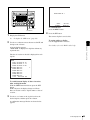
1 Audio level meter section
1 Audio level meters
2 Audio input display
SG DATA
ANA SDI
AE8/EBU
dB OVER
0
SG DATA
ANA SDI
AE8/EBU
dB OVER
0
SG DATA
ANA SDI
AE8/EBU
dB OVER
0
SG DATA
ANA SDI
AE8/EBU
dB OVER
0
-12
-12
-12
-12
-20
-20
-20
-20
-30
-40
-30
-40
-30
-40
-30
-40
-60
CH-
-60
15
CH-
-60
26
CH-
OVER indicator
Reference level
indicator
-60
37
CH-
48
Channel display
a Audio level meters
Depending on the setting of the AUDIO METER SEL
button (see page 15), these show the audio recording levels
(during recording) or audio playback levels (during
playback) of channels 1 to 4 or channels 5 to 8. If an audio
level exceeds 0 dB, the OVER indicator lights.
By means of a maintenance menu setting, you can display
a reference level indicator (“-”) to the right of each meter
when recording.
For details of the maintenace menu, see 8-4 “Maintenance
Menu” on page 114.
b Audio input display
For each channel, the following indicators light to show
the type of the selected audio input signal.
ANA: Analog audio signal
SDI: SDI audio signal
AES/EBU: AES/EBU format digital audio signal
SG: Audio test signal generated by the internal signal
generator
DATA: Non-audio signal
Make the audio input signal selection with the AUDIO
INPUT SEL button (see page 15).
2 Audio settings section
1 MONITOR switch
2 AUDIO MONITOR SEL button
3 AUDIO METER SEL button
4 AUDIO INPUT CH button
L
MIX
R
40
-60
CH-
CH-
CH-
ALL/CH-1
-60
37
CH-
TOP
F REV
48
INPUT SEL
CH-2
F FWD
VIDE
INPUT
CH-3
NEXT
PLAY
PREV
MONITOR
1/2 3/4
5/6 7/8 4
40
-60
26
AUDIO
MONITOR SEL METER SEL INPUT CH
VARIABLE
REC
PRESET
PB
PHONES
40
-60
15
ST
d AUDIO INPUT CH (channel) button
This selects the channel to which the audio input signal
selection applies.
Pressing this button cycles through the following states of
the audio level meter channel display.
• Channel 1 flashing
• Channel 2 flashing
• Channel 3 flashing
• Channel 4 flashing
• Channels 1 to 4 lit
When a channel is flashing, you can select the audio input
signal using the AUDIO INPUT SEL button.
Chapter 2 Names and Functions of Parts
5 AUDIO INPUT SEL button
40
MONITOR
The factory default is for channels 1 to 4 to be selected.
END
6 PHONES jack and volume control knob
a MONITOR switch
Of the two channels (left and right) selected by the AUDIO
MONITOR SEL button (see next item), selects whether
both or one is monitored.
L: The left channel audio is output from the PHONES jack
and the AUDIO MONITOR OUT connector.
R: The right channel audio is output from the PHONES
jack and the AUDIO MONITOR OUT connector.
MIX: Stereo audio is output from the PHONES jack.
Monaural audio, the left and right channels mixed, is
output from the AUDIO MONITOR OUT connector.
b AUDIO MONITOR SEL (selection) button
Of the up to eight audio signal channels, the audio of the
two channels (left and right channels in the case of a stereo
output) selected by this button can be monitored with the
PHONES jack on the front panel and the AUDIO
MONITOR OUT connector on the rear panel.
Pressing this button cycles through the four of the
following channel combinations.
• Channels 1 (left) and 2 (right)
• Channels 3 (left) and 4 (right)
• Channels 5 (left) and 6 (right)
• Channels 7 (left) and 8 (right)
In the status display section, the MONITOR display (see
page 17) changes to reflect the selection.
The factory default is for channels 1 (left) and 2 (right) to
be selected.
You can select whether to monitor both of the selected
channels or only one, using the MONITOR switch (see
page 15).
When audio is in eight-channel mode
On channels 5 to 8, you can input only the audio signals
embedded in an SDI signal.
Note
After completing the selection of the audio input signals
with the AUDIO INPUT SEL button, return the audio level
meters to the state in which all channel indications are lit.
e AUDIO INPUT SEL (selection) button
This selects the input signal to the channel with a flashing
display, that has been selected with the AUDIO INPUT
CH button described above.
Pressing this button cycles the selection of the audio input
signal, and the audio input display above the audio level
meter changes to reflect this.
ANA: Analog audio signal input to the AUDIO IN
connector
SDI: SDI audio signal input to the SDI IN connector
AES/EBU: AES/EBU format digital audio signal input to
the DIGITAL AUDIO (AES/EBU) IN connector
SG: Audio test signal generated by the internal signal
generator
f PHONES jack and volume control knob
The jack is a standard stereo jack. Connect stereo
headphones with an impedance of 8 ohms, to monitor the
audio during recording, playback, and editing. (Non-audio
signals are muted.) The monitored channel is selected by
the AUDIO MONITOR SEL button (see page 15) and
MONITOR switch (see page 15).
Adjust the volume with the knob. You can also cause this
to simultaneously adjust the output volume from the
AUDIO MONITOR OUT connector on the rear panel. To
do this, in the setup menu, set extended menu item 114
“AUDIO MONITOR OUTPUT LEVEL” to “var.”
c AUDIO METER SEL (selection) button
When using MPEG IMX format in eight-channel mode,
select whether the audio level meters should display
channels 1 to 4 or channels 5 to 8.
Pressing this button toggles the selection, and the audio
level meter channel display also changes.
2-1 Front Panel
15
3 Audio level adjustment section
ALL indicator
VARIABLE
REC
PRESET
PB
ALL/CH-1
CH-2
CH-3
CH-4
Chapter 2 Names and Functions of Parts
2 ALL/CH-1, CH-2 to CH-4 adjustment knobs
1 VARIABLE switch
a VARIABLE (audio level adjustment selector)
switch
This selects which of the input audio and playback audio
has the level adjusted by the ALL/CH-1, and CH-2 to CH4 adjustment knobs.
REC: Adjust the input audio levels. The playback audio
levels are fixed at their preset values.
PRESET: Do not adjust the audio levels.
PB: Adjust the playback audio levels. The input audio
levels are fixed at their preset values.
b ALL/CH-1, CH-2 to CH-4 (audio level) adjustment
knobs
Depending on the setting of the VARIABLE switch, these
adjust the input audio or playback audio levels of channels
1 to 4.
By the setting of extended menu item 131 “AUDIO
VOLUME,” you can enable the ALL/CH-1 knob to
simultaneously adjust all eight channels. When this
simultaneous adjustment is enabled the ALL indicator
lights.
4 Recording and playback control section
1 PREV button
2 PLAY button
3 NEXT button
PHONES
TOP
NEXT
PLAY
PREV
F REV
F FWD
STOP
REC
END
4 STOP button
5 REC button
a PREV (previous) button
Press this button, turning it on, to show the first frame of
the current clip. While the first frame of a clip is shown,
pressing this button jumps to the beginning of the previous
clip.
This button is also used together with other buttons for the
following operations.
16
2-1 Front Panel
Reverse direction high-speed search: Hold down the
PLAY button, and press this button. A high-speed
search in the reverse direction is carried out.
Displaying the first frame of the first clip: Hold down
the SHIFT button, and press this button.
b PLAY (playback) button
To start playback, press this button, turning it on.
c NEXT button
Press this button, turning it on, to jump to the next clip, and
show the first frame.
This button is also used together with other buttons for the
following operations.
Forward direction high-speed search: Hold down the
PLAY button, and press this button. A high-speed
search in the forward direction is carried out.
Displaying the last frame of the last clip: Hold down the
SHIFT button, and press this button.
d STOP button
To stop recording or playback, press this button, turning it
on. The frame at the stop point appears.
The unit enters standby off mode when you press this
button with the SHIFT button held down. It returns from
standby off mode to the original state when you press this
button again with the SHIFT button held down. (The lit or
unlit status of the STOP button does not change.)
This unit can automatically enter standby off mode
whenever a specified time elapses in disc stop mode. For
details, see the description of extended menu item 501
“STILL TIMER” (page 103).
e REC (record) button
To start recording, hold down this button, and press the
PLAY button. The recording takes place on an unrecorded
part of the disc.
To stop recording, press the STOP button.
This creates a clip of the recorded portion.
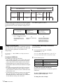
5 Status display section
1 MONITOR display
2 INPUT display
3 Time data display
INPUT
i.LINK
SDI
CMPST
Y-R,B
SG
EDIT REMOTE [9P iLINK]
VITC VIUB COUNTER VITC
HOURS
MINUTES
MONITOR
1/2 3/4
AUDIO
18 24 BIT
5/6 7/8 4 8 CH
625
525
KEY INH ALARM
REC INH
SECONDS
FRAMES
IMX[50 40 30]
DVCAM
5 AUDIO indicators
6 525/625 indicator
7 IMX/DVCAM indicator
8 Disc loaded mark
a MONITOR (audio monitor channel selection)
display
This shows the audio channels selected by the AUDIO
MONITOR SEL button (see page 15). The displayed
channel audio is output from the PHONES jack on the
front panel and the AUDIO MONITOR OUT connector on
the rear panel, according to the setting of the MONITOR
switch (see page 15).
1/2: channels 1 (left) and 2 (right)
3/4: channels 3 (left) and 4 (right)
5/6: channels 5 (left) and 6 (right)
7/8: channels 7 (left) and 8 (right)
b INPUT (video input signal) display
Shows the currently selected video input signal.
i.LINK: i.LINK compliant DVCAM format digital signal
SDI: SDI video signal
CMPST: Composite video signal
SG: Test video signal from the internal signal generator
Make the video signal input selection with the VIDEO
INPUT SEL button (see page 13).
c Time data display
Normally, this shows the disc playback time, time code, or
user bit information, as selected by the COUNTER
SELECT button (see page 13) and extended menu item
629 “TC SELECT.”
It is also used for error messages, setup menus, and other
displays.
2-1 Front Panel
Chapter 2 Names and Functions of Parts
4 Indicators above the time data display
d Indicators above the time data display
There are the following indicators.
EDIT indicator: This lights when an “Audio Edit Preset”
command is received from an external editor.
REMOTE (9P/i.LINK) indicator: This shows “9P” or
“i.LINK” as follows.
• 9P: When extended menu item 214 “REMOTE
INTERFACE” is set to “9PIN.”
• i.LINK: When extended menu item 214 “REMOTE
INTERFACE” is set to “i.LINK.”
COUNTER indicator: This lights when a counter value
(hours, minutes, seconds, and frames, resettable) is
displayed in the time data display.
TC/VITC (time code type) indicator: This lights when
the COUNTER SELECT button (see page 13) is set to
TC. The time data display shows the time code.
When extended menu item 629 “TC SELECT” is set
to “tc,” this shows “TC,” and when “vitc” is selected,
it shows “VITC.”
UB/VIUB (user bit type) indicator: This lights when the
COUNTER SELECT button is set to UB. The time
data display shows the user bits.
When extended menu item 629 “TC SELECT” is set
to “tc,” this shows “UB,” and when “vitc” is selected
it shows “VIUB.”
VITC indicator: This lights in the following cases.
• In playback mode, when VITC is being read.
(Regardless of what the time data display is
showing.)
• When VITC is being recorded, or in E-E mode 1)
when VITC is recorded due to one of the following
conditions.
- Extended menu item 619 “VITC” is set to “on.”
- There is VITC in the selected video input signal,
and that line has been set to “thru” with extended
menu item 723 “INPUT VIDEO BLANK.”
REC INH (recording inhibit) indicator: This lights in
the following cases.
• When a disc with recording inhibited is loaded.
• When extended menu item 310 “REC INHIBIT” is
set to “on.”
• The format of the recorded part of the disc does not
match the settings of the PDW-1500 (number of
recorded channels, TV system (525/625 selection),
and recording format (DVCAM/IMX50/IMX40/
IMX30 selection)).
KEY INH (key inhibit) indicator: This lights when
“MON./INPUT SEL” or “CONTROL PANEL” is set
to “on” with extended menu item 118 “KEY
INHIBIT.”
ALARM indicator: This lights when condensation
within the PDW-1500, a laser diode fault, or another
hardware error is detected. It goes off when the error
state is cleared. When this indicator is lit, the time data
display shows an error message.
17
For details, see 9-2 “Error Messages” (page 123) and 93 “Alarms” (page 124).
6 Shuttle/jog/variable control block
1) E-E mode: Abbreviation of Electric to Electric mode. The mode in which
input video and audio signals are output after passing only through the
electrical circuits.
1 SHUTTLE button
Chapter 2 Names and Functions of Parts
e AUDIO indicators
During playback, these show the number of channels
recorded on the disc and the number of quantizing bits.
During E-E mode display, the number of recorded
channels and number of data bits set by the maintenance
menu item “AUDIO CONFIG” are shown.
Number of recorded channels:
• 4ch: 4 channels
• 8ch: 8 channels
Number of quantizing bits:
• 16bit: 16 bits
• 24bit: 24 bits
When the DVCAM format is used, these are always 4
channels and 16 bits.
For details of the maintenace menu, see 8-4 “Maintenance
Menu” on page 114.
f 525/625 (TV system) indicator
This shows the TV system selected in basic menu item 013
“525/625 SYSTEM SELECT.”
525 (U): NTSC, 525 scan lines, field frequency 59.94 Hz
525 (J): NTSC (for Japan), 525 scan lines, field frequency
59.94 Hz
625: PAL, 625 scan lines, field frequency 50 Hz
g IMX/DVCAM (recording/playback format)
indicator
During playback, this shows the recording format of the
inserted disc. During E-E display, including recording
mode, and during FAM and FTP connections (see page
73), this shows the recording format set by basic menu
item 031 “RECORDING FORMAT.”
IMX50: MPEG IMX 50 format
IMX40: MPEG IMX 40 format
IMX30: MPEG IMX 30 format
DVCAM: DVCAM format
h Disc loaded mark
This lights while a disc is loaded in the PDW-1500. It
flashes as the disc is inserted, and while it is being ejected.
2 JOG button
3 VAR button
4 Jog/shuttle transport
indicators
SH
U TT
LE
JO G
VAR
T
UT
6 Shuttle dial
5 Jog dial
For details of playback operations with these buttons and
dials, see 4-2-2 “Playback Operation” on page 49.
a SHUTTLE button
To play back in shuttle mode using the shuttle dial, press
this button, turning it on. Pressing the JOG button or
turning the jog dial switches to jog mode.
b JOG button
To play back in jog mode using the jog dial, press this
button, turning it on. Pressing the SHUTTLE button or
turning the shuttle dial switches to shuttle mode.
c VAR (variable) button
To play back in variable speed mode using the shuttle dial,
press this button, turning it on.
d Jog/shuttle transport indicators
These show the playback direction in jog, shuttle, or
variable speed mode.
b (green): Lights during playback in the reverse direction.
B (green): Lights during playback in the forward direction.
x (red): Lights during still image display.
e Jog dial
Turn this for playback in jog mode. Turn clockwise for
forward direction playback, and counterclockwise for
reverse direction playback. In jog mode, the playback
speed varies in the range ±1 times normal speed, according
to the rotation rate of the jog dial. There are no detents.
Normally, you press the JOG button before turning the jog
dial, but it is also possible to make a setting to enable jog
18
2-1 Front Panel
mode directly by turning the dial (set extended menu item
101 “SELECTION FOR SEARCH DIAL ENABLE” to
“dial”).
Chapter 2 Names and Functions of Parts
f Shuttle dial
Turn this for playback in shuttle mode or variable speed
mode. Turn clockwise for forward direction playback, and
counterclockwise for reverse direction playback.
• In shuttle mode, the playback speed varies in the range
±35 times normal speed (using MPEG IMX/DVCAM),
according to the angular position of the shuttle dial.
• In variable speed mode, you can finely adjust the
playback speed from –2 to +2 times normal speed,
according to the angular position of the shuttle dial. You
can vary this playback speed range in extended menu
item 301 “VAR SPEED RANGE FOR
SYNCHRONIZATION.”
The shuttle dial has a detent at the center position, for still
image playback.
Normally, you press the SHUTTLE button before turning
the shuttle dial, but it is also possible to make a setting to
enable shuttle mode directly by turning the dial (set
extended menu item 101 “SELECTION FOR SEARCH
DIAL ENABLE” to “dial”).
a F/MARK1 button and f/MARK2 button
When the THUMBNAIL button (see page 14) is lit, you
can use these for thumbnail selection.
During recording and playback, the F/MARK1 and f/
MARK2 buttons can be pressed with the SET button held
down to record a shot mark 1 or shot mark 2 as an essence
mark.
To delete or change essence marks, use the supplied PDZ1 Proxy Browsing Software.
b G/IN button and g/OUT button
When the THUMBNAIL button (see page 14) is lit, you
can use these for thumbnail selection.
An In or Out point is set when you press the SET button
with the G/IN or g/OUT button held down. The In or Out
point setting is deleted when you press the RESET button
with the G/IN or g/OUT button held down.
c IN indicator and OUT indicator
IN indicator: When an IN point is set, this lights.
If an attempt is made to set the IN point after a
recorded OUT point, this flashes.
OUT indicator: When an OUT point is set, this lights.
If an attempt is made to set the OUT point before a
recorded IN point, this flashes.
Note
When extended menu item 101 “SELECTION FOR
SEARCH DIAL ENABLE” is set to “dial,” after using the
shuttle dial, return it to the center position. If the shuttle
dial is not in the center position, it is possible occasionally
for vibration from other operations to activate the dial, and
start playback in shuttle mode.
7 Arrow buttons
The four arrow buttons are also used as the MARK1
button, MARK2 button, IN button, and OUT button. The
correspondence with the buttons is as follows.
F button: MARK1 button
f button: MARK2 button
G button: IN button
g button: OUT button
You can use these buttons for thumbnail selection, menu
setting operations, setting IN/OUT points, and so on.
1 F/MARK1 button and f/MARK2 button
2 G/IN button and g/OUT button
ESSENCE
MARK
IN
S.SEL
MARK1
OUT
MARK2
3 IN indicator and OUT indicator
2-1 Front Panel
19
2-2 Rear Panel
Chapter 2 Names and Functions of Parts
REF.VIDEO IN
VIDEO IN
VIDEO OUT
1
1 REF. VIDEO IN connectors
2
(SUPER)
AUDIO IN
2/4 AUDIO OUT 1/3
1/3
2/4
1 Analog audio signal inputs/
outputs (see page 21)
5 AUDIO MONITOR OUT connector
DIGITAL AUDIO (AES/EBU)
S400
2
3Analog video signal inputs/
outputs (see page 21)
AUDIO
MONITOR OUT
IN
1/2
3/4
OUT
1/2
SDI
3/4
IN
OUT 1
TIME CODE
2 (SUPER)
IN
S400 (i.LINK) connector
OUT
4Time code inputs/outputs
(see page 22)
REMOTE
5 Power supply section
3 REMOTE connector
4
(see page 22)
(network) connector
2 Digital audio signal inputs/outputs
6 SDI signal inputs/
outputs (see page 22)
(see page 21)
a REF. VIDEO IN (reference video signal input)
connectors (BNC type)
The two connectors form a loop-through connection; when
a reference video signal is input to the left connector, the
same signal is input from the right connector ( ) to a
connected device. When no connection is made to the right
connector, the left connector is automatically terminated
with an impedance of 75 ohms.
b
S400 (i.LINK) connector (6-pin, IEEE1394
compliant)
Connect a DV device, computer, or similar, using an
i.LINK cable.
When the unit is shipped from the factory, the audio output
signal is set to 16 bit/48 kHz/2ch mode. You can change
the audio mode and output channel settings with extended
menu item 831 “DV OUT AUDIO MODE” and extended
menu item 828 “SDI/DV AUDIO OUTPUT SELECT.”
See 8-3-2 “Extended Menu Operations” (page 110) for
more information about how to make these settings.
20
40 V) output from the i.LINK connector of the device
flows into the PDW-1500. This may cause a failure of
the PDW-1500.
• When connecting the PDW-1500 to a device with a 6-pin
i.LINK connector, connect to the 6-pin i.LINK
connector of the other device first.
• Except in playback mode (jog and shuttle modes, etc.), if
you are monitoring the audio signal output from this
connector on another device, the audio signal may sound
differently from the audio signal played back on the
PDW-1500.
c REMOTE (remote control signal) connector (Dsub 9-pin)
To control the PDW-1500 from a controller or VTR
supporting the RS-422A Sony 9-pin VTR protocol,
connect the device to this connector.
d
(network) connector (RJ-45 type)
This is a 10Base-T/100Base-TX/1000Base-T connector
for network connection.
Notes
CAUTION
• If video or audio signals from an external device
connected with the S400 (i.LINK) connector are not
output, disconnect the i.LINK cable and connect it again,
pushing it straight in.
• When the PDW-1500 is connected to a device with a 6pin i.LINK connector by an i.LINK cable, before
unplugging the i.LINK cable, first power off the device
and disconnect the power plug from the outlet. If the
i.LINK cable is unplugged with the device power plug
still connected, a current from an excessive voltage (8 to
For safety, do not connect the connector for peripheral
device wiring that might have excessive voltage to this
port. Follow the instructions in this manual when making
connections.
2-2 Rear Panel
e AUDIO MONITOR OUT connector (RCA-pin)
This outputs an audio signal for monitoring.
The monitored channel is selected by the combination of
the AUDIO MONITOR SEL button (see page 15) and
MONITOR switch (see page 15).
1 Analog audio signal inputs/outputs
1 AUDIO IN 1/3, 2/4 connectors
2 AUDIO OUT 1/3, 2/4 connectors
AUDIO IN
2/4 AUDIO OUT 1/3
1/3
a DIGITAL AUDIO (AES/EBU) IN (digital audio
input) 1/2, 3/4 connectors (BNC type)
These input AES/EBU format digital audio signals. The
left connector (1/2) corresponds to audio channels 1 and 2,
and the right connector (3/4) corresponds to audio
channels 3 and 4.
2/4
For details of the maintenace menu, see 8-4 “Maintenance
Menu” on page 114.
b AUDIO OUT (analog audio signal output) 1/3, 2/4
connectors (XLR 3-pin, male)
These output analog audio signals.
When the unit is shipped from the factory, the 1/3
connector is set to audio channel 1, and the 2/4 connector
is set to audio channel 2. You can change these settings
with extended menu item 824 “ANALOG LINE OUTPUT
SELECT.”
You can set the output level with the maintenance menu
item “AUDIO CONFIG.” (Factory default setting: +4 dB)
Non-audio signals are muted.
To treat the input and output signals of these connectors as
non-audio signals, set the maintenance menu item
“AUDIO CONFIG”-“NON-AUDIO INPUT” (recording)
and extended menu item 823 “NON-AUDIO FLAG PB”
(playback).
See 8-3-2 “Extended Menu Operations” (page 110) for
more information about how to make extended menu
settings.
See 8-4-2 “Maintenance Menu Operations” (page 116)
for more information about how to make maintenance
menu settings.
3 Analog video signal inputs/outputs
1 VIDEO IN connectors
2 VIDEO OUT 1, 2 (SUPER) connectors
VIDEO IN
See 8-3-2 “Extended Menu Operations” (page 110) for
more information about how to make these settings.
For details of the maintenace menu, see 8-4 “Maintenance
Menu” on page 114.
2 Digital audio signal inputs/outputs
1 DIGITAL AUDIO (AES/EBU) IN 1/2, 3/4 connectors
2 DIGITAL AUDIO (AES/EBU)
OUT 1/2, 3/4 connectors
Chapter 2 Names and Functions of Parts
a AUDIO IN (analog audio signal input) 1/3, 2/4
connectors (XLR 3-pin, female)
These input analog audio signals.
With the AUDIO INPUT SEL button (see page 15), you
can select whether the signal input to connector 1/3 is
assigned to audio channel 1or 3, and whether the signal
input to connector 2/4 is assigned to audio channel 2 or 4.
You can set the reference input level with the maintenance
menu item “AUDIO CONFIG.” (Factory default setting:
+4 dB)
b DIGITAL AUDIO (AES/EBU) OUT (digital audio
output) 1/2, 3/4 connectors (BNC type)
These output AES/EBU format digital audio signals.
When the unit is shipped from the factory, the 1/2
connector is set to audio channel 1/2, and the 3/4 connector
is set to audio channel 3/4. You can change these settings
with extended menu item 827 “AES/EBU AUDIO
OUTPUT SELECT.”
VIDEO OUT
1
2
(SUPER)
a VIDEO IN (analog video input) connectors (BNC
type)
These input composite video signals.
The two connectors form a loop-through connection; when
a signal is input to the left connector, the same signal is
output from the right connector ( ) forming a bridge
connection to the connected device.
When no connection is made to the right connector, the left
connector is automatically terminated with an impedance
of 75 ohms.
DIGITAL AUDIO (AES/EBU)
IN
1/2
3/4
OUT
1/2
3/4
b VIDEO OUT 1, 2 (SUPER) (analog video output 1,
2 (superimpose)) connectors (BNC type)
These output composite video signals.
2-2 Rear Panel
21
The output from the VIDEO OUT2 (SUPER) connector
can have time code, menu settings, alarm messages, and
other text information superimposed.
on/standby switch indicator on the front panel is lit red (the
PDW-1500 is in the standby state), then press this switch
on the a side.
4 Time code inputs/outputs
6 SDI signal inputs/outputs
Chapter 2 Names and Functions of Parts
1 TIME CODE IN connector
1 SDI IN connector
2 SDI OUT1/2 (SUPER) connectors
2 TIME CODE OUT connector
SDI
TIME CODE
IN
IN
OUT 1
2 (SUPER)
OUT
a TIME CODE IN connector (BNC type)
This inputs an SMPTE time code generated by an external
device.
b TIME CODE OUT connector (BNC type)
This outputs the following time code, depending on the
operating state of the PDW-1500.
During playback: playback time code
During recording: the time code from the internal time
code generator or the time code input to the TIME
CODE IN connector.
When extended menu item 611 “TC OUTPUT
PHASE IN EE MODE” is set to “muting,” no time
code is output.
5 Power supply section
1 -AC IN connector
a SDI IN (SDI signal input) connector (BNC type)
This inputs an SDI format video/audio signal.
When you select the signal input to this connector with the
VIDEO INPUT SEL button, in the status display section,
the INPUT display SDI indicator lights.
b SDI OUT1/2 (SUPER) (SDI signal outputs 1, 2
(superimpose)) connectors (BNC type)
These output SDI format video/audio signals.
When the unit is shipped from the factory, audio signal
output is 8 channels with no switching, and RP188 time
code output is set to on. You can change these settings with
extended menu item 828 “SDI/DV AUDIO OUTPUT
SELECT” and extended menu item 920 “SD-SDI H-ANC
CONTROL.”
The output from the SDI OUT2 (SUPER) connector can
have time code, menu settings, alarm messages, and other
text information superimposed. To turn superimposition
off, set the maintenance menu item “OTHERS”-“SDI2
SUPER” to “OFF.”
2 POWER switch
- AC IN
POWER
a -AC IN (AC power input) connector
Connect to an AC power supply, using an optional power
cord (see page 135).
b POWER (main power) switch
Press the ^ side to power on. Press the a side to power off.
When using the PDW-1500, normally leave the POWER
switch in the ^ (on) position, and use the on/standby switch
to switch the PDW-1500 between the operating state and
standby state.
Note
When you set the on/standby switch on the front panel to
the 1 position, data is saved before powering off. Before
turning off the main power switch, be sure to check that the
22
2-2 Rear Panel
To treat the input and output signals of these connectors as
non-audio signals, set the maintenance menu item
“AUDIO CONFIG”-“NON-AUDIO INPUT” (recording)
and extended menu item 823 “NON-AUDIO FLAG PB”
(playback).
See 8-3-2 “Extended Menu Operations” (page 110) for
more information about how to make extended menu
settings.
See 8-4-2 “Maintenance Menu Operations” (page 116)
for more information about how to make maintenance
menu settings.
Preparations
Chapter
3
3-1 Connections and Settings
Note
Production of some of the peripherals and related devices
described in this chapter has been discontinued. For advice
about choosing devices, please contact your Sony dealer or
a Sony sales representative.
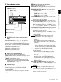
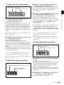
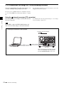
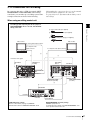
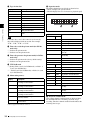
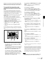
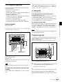
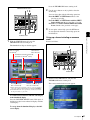
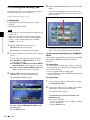
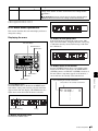
3-1-1 Connecting an External Monitor
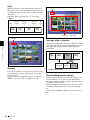
Connecting a video monitor to the VIDEO OUT 1, VIDEO
OUT 2 (SUPER), SDI OUT1, or SDI OUT 2 (SUPER)
connector of this unit enables you to see the output video
on the monitor screen.
To superimpose text information, for example, time code
and alarm messages, use the VIDEO OUT 2 (SUPER) or
SDI OUT 2 (SUPER) connector. You can select the kind
of text information to display using basic menu item 005
“DISPLAY INFORMATION SELECT.”
For detailed information about basic menu items and how
to make menu settings, see 8-2 “Basic Setup Menu” on
page 92.
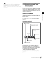
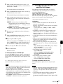
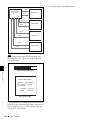
Connect a video monitor as example 1 or 2 shown in the
following figure.
1, 2: 75 Ω coaxial cable (not supplied)
To composite video input
connector
1
VIDEO OUT 2(SUPER)
To SDI input connector
2
SDI OUT 2(SUPER)
Video monitor
PDW-1500
3-1 Connections and Settings
23
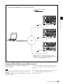
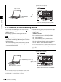
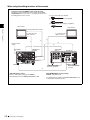
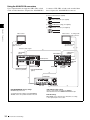
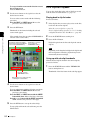
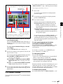
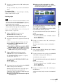
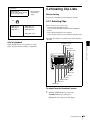
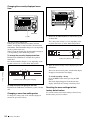
3-1-2 Connections for Using PDZ-1 Proxy Browsing Software
Using the supplied PDZ-1 Proxy Browsing Software, you
can carry out simple editing with proxy AV data.
For information about how to use the software, refer to the
Help provided in the software.
For an overview of PDZ-1 and how to install the software,
see 5-4 “Using PDZ-1 Proxy Browsing Software” on page
69.
Using the
(network) connector (FTP connection)
Chapter 3 Preparations
The following shows an example of an FTP (File Transfer
Protocol) connection.
For details of the network-related settings, see “To change
network settings” (page 117).
Note
To use PDZ-1 requires the PDW-1500 IP address and
other network-related settings to be made beforehand.
Connecting this unit directly to a laptop computer
1: Network cable (not supplied)
1
Laptop computer
(network) connector
To network connector
PDW-1500
Make sure the remote control switch (see page
13) is set to “NETWORK” and extended menu
item 257 “NETWORK ENABLE” is set to “net.”
24
3-1 Connections and Settings
Connecting three PDW-1500 units to a laptop computer via a LAN.
1: Network cable (not supplied)
PDW-1500
(network) connector
PDW-1500
(network) connector
PDW-1500
Chapter 3 Preparations
(network) connector
1
Laptop computer
1
LAN
1
To network connector
1
Make sure the remote control switch (see page 13) is set to
“NETWORK” on each of the three PDW-1500 units and extended
menu item 257 “NETWORK ENABLE” is set to “net.”
Using the S400 (i.LINK) connector (FAM connection)
The following shows an example of a FAM (file access
mode) connection.
Note
The PDZ-1 Proxy Browsing Software must be installed in
advance.
The required FAM driver is also installed when you install
the PDZ-1 software.
See 5-4 “Using PDZ-1 Proxy Browsing Software” (page
69) for more information about installing the PDZ-1
software.
Some limitations apply to FAM connections. For details,
see 7-2 “File Access Mode File Operations (for
Windows)” (page 79).
3-1 Connections and Settings
25
1: i.LINK cable (not supplied)
Laptop computer
1
To i.LINK (IEEE1394)
connector
S400 (i.LINK)
Chapter 3 Preparations
PDW-1500
Make sure extended menu item 215 “i.LINK
MODE” is set to “FAM (PC REMOTE).”
3-1-3 Connecting to a Nonlinear Editing System
You can send video/audio signals (AV/C data) from this
unit to a nonlinear editing system connected to the S400
(i.LINK) connector.
The following figure shows an example connection.
Notes
• The S400 (i.LINK) connector of this unit outputs
video/audio signals in DVCAM format. Data recorded in
MPEG IMX format is output after being converted into
DVCAM format.
• The nonlinear editing system to be used being connected
to this unit requires editing software (not supplied)
supporting DVCAM format.
• Make the following settings before transferring video/
audio signals (AV/C data) from this unit to a nonlinear
editing system.
Audio mode selection
Use extended menu item 831 “DV OUT AUDIO
MODE” to select either of the following.
4ch: 12 bit/32 kHz/4 ch
2ch: 16 bit/48 kHz/2 ch (Factory default setting)
Audio output channel selection
Select the audio output channels with extended menu
item 828 “SDI/DV AUDIO OUTPUT SELECT.”
For information about how to make extended menu item
settings, see 8-3-2 “Extended Menu Operations” on
page 110.
1: i.LINK cable (not supplied)
To i.LINK(IEEE1394) connector 1
S400 (i.LINK)
Laptop computer
(With editing software supporting
DVCAM format installed)
PDW-1500
Make sure extended menu item 215 “i.LINK MODE”
is set to “AV/C.”
For the method of transferring video/audio signals (AV/C
data) to a nonlinear editing system, refer to the manual
provided with the editing software to be used.
26
3-1 Connections and Settings
3-1-4 Connections for Cut Editing
By connecting this unit to a VTR (for example, MSWM2000/M2000P or DSR-2000/2000P) and an editing
control unit, you can make up a cut editing system. Some
example connections are shown in the following.
When making the connections, also refer to the manuals
provided with the equipment to be connected.
See page 33 for more information about editing control
unit settings.
When using an editing control unit
Cut editing system comprising this unit as a player, an
MSW-M2000/M2000P unit as a recorder, and a BVE-700
editing control unit.
Chapter 3 Preparations
1: 75 Ω coaxial cable (not supplied)
2: 9-pin remote control cable (not supplied)
3: Cable with RCA phono plugs (not supplied)
Video monitor
Video monitor
To analog audio input connector
To composite video
input connector
To composite video input connector
3
1
1
1
Reference video signal
1
VIDEO OUT 2
(SUPER)
REF.VIDEO
IN
REF.VIDEO
INPUT
SDI INPUT
AUDIO MONITOR
OUT
SDI OUT 1
REMOTE
PDW-1500 (player)
REMOTE 1IN(9P)
MSW-M2000/M2000P
(recorder)
COMPOSITE VIDEO
OUTPUT 3(SUPER)
2
2
RECORDER
1
PLAYER-1
AC IN
BVE-700
PDW-1500 (player) settings
Remote control switch (see page 13): REMOTE
Extended menu item 214 “REMOTE INTERFACE”: 9PIN
REF.VIDEO IN
MSW-M2000/M2000P (recorder) settings
REMOTE 1(9P) button: Lit
For details about the settings of the MSW-M2000/M2000P, refer
to the operation manual for the unit.
3-1 Connections and Settings
27
When using the editing functions of the recorder
Connections using the REMOTE connector (D-sub 9-pin):
Cut editing system comprising this unit as a player and an MSWM2000/M2000P unit as a recorder. For cut editing, the system uses
the editing functions of the recorder.
1: 75 Ω coaxial cable (not supplied)
2: 9-pin remote control cable (not supplied)
3: Cable with RCA phono plugs (not supplied)
Video monitor
Video monitor
Chapter 3 Preparations
To analog audio input connector
To composite video
input connector
To composite video
input connector
3
1
1
1
Reference video
signal
1
REF.VIDEO
IN
VIDEO OUT 2
(SUPER)
REF.VIDEO
INPUT
SDI INPUT
AUDIO MONITOR
OUT
SDI OUT 1
REMOTE
PDW-1500 (player)
COMPOSITE VIDEO
OUTPUT 3(SUPER)
REMOTE 1OUT(9P)
MSW-M2000/M2000P
(recorder)
2
PDW-1500 (player) settings
Remote control switch (see page 13): REMOTE
Extended menu item 214 “REMOTE INTERFACE”: 9PIN
MSW-M2000/M2000P (recorder) settings
REMOTE 1(9P) button: Unlit
For details about the settings of the MSW-M2000/M2000P, refer
to the operation manual for the unit.
28
3-1 Connections and Settings
Connections using the S400 (i.LINK) connector:
Cut editing system comprising this unit as a player and a DSR2000/2000P unit as a recorder. For cut editing, the system uses
the editing functions of the recorder. In this system, all signals
such as the video/audio signals and control signals are
transferred through the S400 (i.LINK) connector.
1: 75 Ω coaxial cable (not supplied)
2: Cable with RCA phono plugs (not supplied)
3: i.LINK cable (not supplied)
Chapter 3 Preparations
Video monitor
Video monitor
To analog audio input connector
To composite video
input connector
1
To composite video
input connector
2
1
3
VIDEO OUT 2
(SUPER)
i.LINK (optional DSBK-190)
AUDIO MONITOR
OUT
S400 (i.LINK)
PDW-1500 (player)
VIDEO OUT 3(SUPER)
PDW-1500 (player) settings
Remote control switch (see page 13): REMOTE
Extended menu item 214 “REMOTE INTERFACE”: i.LINK
DSR-2000/2000P
(recorder)
DSR-2000/2000P (recorder) settings
i.LINK button: Lit
SDTI/i.LINK button: i.LINK
For details about the settings of the DSR-2000/2000P, refer to the
operating instructions for the unit.
3-1-5 Connections for Clip Audio
Insert Editing
By connecting this unit to a VTR (for example, MSWM2000/M2000P or DSR-2000/2000P), you can make up a
clip audio insert editing system. Some example
connections are shown in the following.
Notes
EBU) input, or 2 channels of ANALOG input are
supported. Check the input channels before making
connections.
See page 70 for more information about clip audio insert
editing.
When making the connections, also refer to the manuals
provided with the equipment to be connected.
See page 33 for more information about editing control
unit settings.
• An editing control unit such as the BVE-700 is required
because this unit has no functions for controlling other
devices.
• The MSW-M2000/M2000P shown in the figure supports
up to 8 channels of audio output. The number of
channels which may be input to this unit varies
depending on the type of input signal. Up to 8 channels
of SDI input, 4 channels of DIGITAL AUDIO (AES/
3-1 Connections and Settings
29
Using the ANALOG IN connectors
Up to 2 input channels are supported. CH1, CH3, or both
can be recorded when there is input to the ANALOG IN1/
3 connector. CH2, CH4, or both can be recorded when
there is input to the ANALOG IN2/4 connector.
1: 75 Ω coaxial cable (not supplied)
2: 9-pin remote control cable (not supplied)
3: Cable with RCA phono plugs (not supplied)
4: Cable with XLR connectors (not supplied)
Chapter 3 Preparations
Video monitor
Video monitor
To analog audio
input connector
To composite video
input connector
To composite video
input connector
1
Reference video signal
3
1
1
REF.VIDEO
INPUT
REF.VIDEO IN
VIDEO OUT 2
(SUPER)
AUDIO OUTPUT
4
REMOTE
REMOTE 1IN(9P)
COMPOSITE VIDEO
OUTPUT 3(SUPER)
AUDIO
MONITOR
OUT
AUDIO IN
PDW-1500
(recorder)
MSW-M2000 /M2000P
(player)
2
2
RECORDER
AC IN
PLAYER-1
BVE-700
MSW-M2000/M2000P (player) settings
REMOTE 1(9P) button: Lit
For details about the settings of the MSW-M2000/
M2000P, refer to the operation manual for the unit.
30
3-1 Connections and Settings
REF.VIDEO IN
1
PDW-1500 (recorder) settings
Remote control switch (see page 13): REMOTE
Extended menu item 214 “REMOTE INTERFACE”: 9pin
BVE-700 settings
EDIT MODE section: Select the A1 to A8 buttons, according
to the required input to the recorder.
Using the DIGITAL AUDIO (AES/EBU) IN connectors
Up to 4 input channels are supported.
1: 75 Ω coaxial cable (not supplied)
2: 9-pin remote control cable (not supplied)
3: Cable with RCA phono plugs (not supplied)
Video monitor
To composite video
input connector
To composite video
input connector
Reference video signal
1
To analog audio
input connector
Chapter 3 Preparations
Video monitor
1
3
1
REF.VIDEO
INPUT
REF.VIDEO IN
VIDEO OUT 2
(SUPER)
AUDIO OUTPUT
(AES/EBU)
1
AUDIO
MONITOR
OUT
DIGITAL AUDIO
(AES/EBU)
REMOTE
REMOTE 1IN(9P)
COMPOSITE VIDEO
OUTPUT 3(SUPER)
MSW-M2000 /M2000P
(player)
PDW-1500
(recorder)
2
2
RECORDER
AC IN
PLAYER-1
BVE-700
MSW-M2000/M2000P (player) settings
REMOTE 1(9P) button: Lit
For details about the settings of the MSW-M2000/
M2000P, refer to the operation manual for the unit.
REF.VIDEO IN
1
PDW-1500 (recorder) settings
Remote control switch (see page 13): REMOTE
Extended menu item 214 “REMOTE INTERFACE”: 9pin
BVE-700 settings
EDIT MODE section: Select the A1 to A8 buttons, according
to the required input to the recorder.
3-1 Connections and Settings
31
Using the SDI IN connector
Up to 8 input channels are supported.
1: 75 Ω coaxial cable (not supplied)
2: 9-pin remote control cable (not supplied)
3: Cable with RCA phono plugs (not supplied)
Chapter 3 Preparations
Video monitor
Video monitor
To composite video
input connector
To composite video
input connector
Reference video signal
1
To analog audio
input connector
1
REF.VIDEO
INPUT
REF.VIDEO IN
VIDEO OUT 2
(SUPER)
SDI OUTPUT1
1
AUDIO
MONITOR
OUT
SDI IN
REMOTE
REMOTE 1IN(9P)
COMPOSITE VIDEO
OUTPUT 3(SUPER)
3
1
MSW-M2000 /M2000P
(player)
PDW-1500
(recorder)
2
2
RECORDER
AC IN
PLAYER-1
BVE-700
MSW-M2000/M2000P (player) settings
REMOTE 1(9P) button: Lit
For details about the settings of the MSW-M2000/
M2000P, refer to the operation manual for the unit.
32
3-1 Connections and Settings
REF.VIDEO IN
1
PDW-1500 (recorder) settings
Remote control switch (see page 13): REMOTE
Extended menu item 214 “REMOTE INTERFACE”: 9pin
BVE-700 settings
EDIT MODE section: Select the A1 to A8 buttons, according
to the required input to the recorder.
3-1-6 Editing Control Unit Settings
When connecting an editing control unit to use with this
unit, make the following settings, depending on the editing
control unit model.
BVE-600/700/900/910/2000/9100
Set VTR constants as follows.
VTR CONSTANT 1
1
2
3
4
5
6
7
8
1
VTR CONSTANT 2
2
3
4
5
6
7
8
525/60
A0
91
00
96
05
05
03
80
0A
07
FE
00
80
5A
FF
5A
625/50
A1
91
00
7D
05
05
03
80
0A
07
FE
00
80
4C
FF
4B
Chapter 3 Preparations
Line
mode
FXE-100/120
Set VTR constants as follows.
Line
mode
1
2
3
4
5
6
7
8
9
10
11
12
13
14
15
525/60
A0
91
00
96
05
05
03
80
0A
07
FE
00
80
5A
FF
625/50
A1
91
00
7D
05
05
03
80
0A
07
FE
00
80
4C
FF
RM-450
Set the DIP switches as follows.
• Left switch
Line
mode
7
6
5
4
3
2
1
0
525/60
OFF –
–
OFF –
–
–
–
625/50
OFF –
–
OFF –
–
–
–
5
4
2
1
0
• Right switch
Line
mode
7
6
525/60
OFF –
OFF ON
OFF OFF ON
ON
625/50
ON
OFF ON
OFF OFF ON
ON
–
3
PVE-500
No settings required.
3-1 Connections and Settings
33
3-2 Setup
The principal setup operations before operating this unit
can be carried out using setup menus.
The setup menus of this unit comprise a basic setup menu
and an extended setup menu. The contents of these menus
are as follows.
3-3 Setting the Date and
Time
When using this unit for the first time, you should set the
date and time as follows.
1
Chapter 3 Preparations
Basic setup menu:
• Items relating to the hours meter
• Items relating to operation
• Items relating to menu banks
EJECT
ACCESS
NETWORK
LOCAL
REMOTE
Extended setup menu:
• Items relating to control panels
• Items relating to the remote control interface
• Items relating to editing operations
• Items relating to preroll
• Items relating to disc protection
• Items relating to the time code, metadata, and UMID
• Items relating to video control
• Items relating to audio control
• Items relating to digital processing
For detailed information about the items, except for the
basic menu items relating to the hours meter, of these
menus and how to use them, see Chapter 8 “Menus” (page
91). For detailed information about menu operations
relating to the hours meter, see 9-1-1 “Digital Hours
Meter” (page 122).
MONITOR
L
MIX
R
SG DATA
ANA SDI
AE8/EBU
dB OVER
0
SG DATA
ANA SDI
AE8/EBU
dB OVER
0
SG DATA
ANA SDI
AE8/EBU
dB OVER
0
-12
-12
-12
-20
-20
-20
-20
-30
-40
-30
-40
-30
-40
-30
-40
-60
CH-
-60
15
PHONES
CH-
-60
26
CH-
ALL/CH-1
CH-
MINUTES
MONITOR
1/2 3/4
AUDIO
5/6 7/8 4 8 CH
18 24 BIT
48
INPUT SEL
CH-2
VIDEO
INPUT SEL
CH-3
625
525
COUNTER
SELECT
CH-4
STOP
KEY INH ALARM
REC INH
SECONDS
SH
FRAMES
HOLD
SUB
CLIP
SYS MENU
MENU
THUMB
NAIL
F REV
F FWD
LE
JO G
VAR
ESSENCE
MARK
SHIFT
SET RESET
S.SEL
MARK1
REC
IN
TOP
UT T
IMX[50 40 30]
DVCAM
CLIP
MENU
NEXT
PLAY
PREV
EDIT REMOTE [9P iLINK]
VITC VIUB COUNTER VITC
INPUT
i.LINK
SDI
CMPST
Y-R,B
SG
HOURS
-60
37
AUDIO
MONITOR SEL METER SEL INPUT CH
VARIABLE
REC
PRESET
PB
OUT
END
MARK2
4 2,3
1
3
Holding down the SHIFT button, press the MENU
button.
The system menu appears on the monitor screen.
2
Select “DATE/TIME PRESET” using the F button or
f button, then press the g button.
The date and time setting screen appears on the
monitor, allowing you to set the following items.
• YEAR: Calendar year
• MONTH: Month
• DAY: Day
• TIME: Time
• TIME ZONE: Time zone (Difference from UTC)
This unit allows four different sets of menu settings to be
saved in what are termed “menu banks” numbered 1 to 4.
Saved sets of menu settings can be recalled for use as
required.
For more information about the menu banks, see “Menu
bank operations (menu items B01 to B13)” (page 97) and
the description of maintenance menu item “SETUP
MAINTENANCE” – “SETUP BANK4” (page 115).
SG DATA
ANA SDI
AE8/EBU
dB OVER
0
-12
3
Set the date, time and time zone.
You can change the setting of the flashing digits.
To change the flashing digits
Use the arrow buttons (G, g).
To increase or decrease the values of the flashing
digits
Use the arrow buttons (F, f) or jog dial.
4
Press the SET button.
The date, time and time zone settings are stored.
To return to the previous menu page
Press the MENU button.
To exit the menu
Press the MENU button twice in succession.
34
3-2 Setup / 3-3 Setting the Date and Time
Note
The time zone is reset to the factory default when you
execute the maintenance menu item “RESET ALL
SETUP.” You will need to set it again. The date and time
are not reset.
3-4 Superimposed Text
Information
The video signal output from the VIDEO OUT 2 (SUPER)
connector or the SDI OUT 2 (SUPER) connector contains
superimposed text information, including time code, menu
settings, and alarm messages.
Adjusting the text display
Chapter 3 Preparations
You can adjust the position, size and type of the
superimposed text using basic menu items 002, 003, 005,
009, 011, and 012.
For details, see 8-2-1 “Items in the Basic Setup Menu”
(page 92).
Information displayed
1Type of time data
2Time code reader drop frame
mark (for 525 line mode only)
3Time code generator drop
frame mark (for 525 line
mode only)
Time data
T C R
B 1
4VITC field mark
0 0 : 0 4 . 4 7 . 0 7 *
P L A Y
L O C K
7Playback condition
mark
6Operation mode
5Menu setting states
Note
The display shown above corresponds to the factory
default settings of the unit. You can change the type of
information to be displayed in the lower line of the display
by changing the setting of basic menu item 005
“DISPLAY INFORMATION SELECT.”
For details, see 8-2-1 “Items in the Basic Setup Menu”
(page 92).
3-4 Superimposed Text Information
35
a Type of time data
Display
Meaning
Chapter 3 Preparations
CNT
Counter data
TCR
TC reader time code data
UBR
TC reader user bits data
TCR.
VITC reader time code
UBR.
VITC reader user bits data
TCG
TC generator time code
UBG
TC generator user bits data
IN
IN point time data
OUT
OUT point time data
DUR
Duration between IN point and OUT
point
f Operation mode
The field is divided into two blocks as shown below.
• Block A displays the operation mode.
• Block B displays the servo lock status or playback speed.
A
Display
Block A
Note
If the time data or user’s bits cannot be read correctly,
they will be displayed with an asterisk. For example,
“T*R”, “U*R”, “T*R.” or “U*R.”.
DISC OUT
b Time code reader drop frame mark (for 525 line
mode only)
“.”: Indicates drop frame mode
“:”: Indicates non-drop-frame mode
c Time code generator drop frame mark (for 525 line
mode only)
“.”: Indicates drop frame mode (factory default setting)
“:”: Indicates non-drop-frame mode
Operation mode
Block B
Disc is not loaded.
LOADING
Disc is being loaded.
UNLOADING
Disc is being unloaded.
STANDBY OFF
Standby off mode
STOP
Stop mode
NEXT
Cuing up to the first frame of the
next clip.
PREV
Cuing up to the first frame of the
current clip.
F.FWD
Fast forward search
F.REV
Fast reverse search
PLAY
d VITC field mark
“ ” (blank): Fields 1 and 3 (for 525/60 mode) or fields 1, 3,
5 and 7 (for 625/50 mode)
“ * ”: Fields 2 and 4 (for 525/60 mode) or fields 2, 4, 6 and
8 (for 625/50 mode)
e Menu setting states 1)
PLAY
Playback mode (servo unlocked)
LOCK
REC
REC
Playback mode (servo locked)
Record mode (servo unlocked)
LOCK
Record mode (servo locked)
JOG
STILL
A still picture in jog mode
JOG
FWD
Jog mode in forward direction
JOG
REV
Jog mode in reverse direction
STILL
A still picture in shuttle mode
Display
Description
SHUTTLE
B1
The current menu settings are the same as
the settings in menu bank 1.
SHUTTLE
(Speed) Shuttle mode
VAR
(Speed) Variable speed mode
B2
The current menu settings are the same as
the settings in menu bank 2.
TOP 0001/xxxx
Cuing up to the first frame of the
first clip.
B3
The current menu settings are the same as
the settings in menu bank 3.
END xxxx/xxxx
Cuing up to the last frame of the
last clip.
B4
The current menu settings are the same as
the settings in menu bank 4.
PREROLL
Cuing up during thumbnail search
DF
The current menu settings are the same as
the factory defaults.
No display
The current menu settings are different from
all of the above.
1) This is supported from firmware version 1.4.
36
B
3-4 Superimposed Text Information
g Playback condition mark
One of three channel condition marks is displayed when
the ACCESS indicator is lit during any mode except
recording. The three channel condition marks indicate the
following three stages.
Display
Description
Green condition
There is no problem with the
playback condition. This unit
and the disc can be used just
as they are. This
corresponds to the “green”
channel condition indicator of
a VTR.
Yellow condition
The playback condition has
deteriorated to some degree.
There are no read errors, but
you should take the action
described in the next section.
This corresponds to the
“yellow” channel condition
indicator of a VTR.
Red condition
The playback condition has
deteriorated. There are no
read errors,a) but you should
take the action described in
the next section. This
corresponds to the “red”
channel condition indicator of
a VTR.
a) Read errors will occur if the playback condition continues to deteriorate.
If a read error occurs, a “Disc Error!” alarm appears in the time data
display, the picture freezes, and audio is muted.
To display playback condition marks, set basic menu item
012 “CONDITION DISPLAY ON VIDEO MONITOR”
to “ena,” and set basic menu item 005 “DISPLAY
INFORMATION SELECT” to “T&sta.”
For details about operation, see 8-2-2 “Basic Menu
Operations” (page 95).
• Deteriorating laser diodes performance
The performance of the laser diodes used in optical
heads can worsen with age, leading to deteriorating
playback conditions.
You can use the digital clock to check the total optical
output time of optical heads.
For details, see 9-1-1 “Digital Hours Meter” (page 122)
about this setting.
Refer to the Maintenance Manual for an approximate
guide to when it is time to replace optical heads.
To prevent playback conditions from
deteriorating
Pay attention to the following points when handling discs.
• Do not open disc cartridges and touch discs directly with
your hands.
• Do not store for long periods in locations which are
dusty or exposed to air circulated by fans.
• Do not store for long periods under high temperatures or
in locations exposed to direct sunlight.
Chapter 3 Preparations
Name
If playback conditions have deteriorated
If a yellow or red playback condition mark appears, check
the following points.
Whether the disc displays the same playback condition
on other XDCAM devices: If so, the surface of the
disc may be dirty or scratched, or the performance of
the recording layers on the disc may have worsened
due to age. Do not use discs with these symptoms.
Whether every disc inserted into an XDCAM device
displays the same playback conditions: If so, the
performance of the laser diodes may have deteriorated.
Check the total optical output time.
Playback condition displays
You can be alerted in advance to deteriorating playback
conditions and to error correction rates which are
approaching their limits.
Deteriorating playback may be due to the following
causes.
• Scratches and dust on the disc surface
This includes fingerprints, dust from the air, tar from
cigarette smoke, and so on.
Scratches and soiling which occur before recording are
not a problem because they are registered in advance as
defects, and recording avoids them. However, scratches
and soiling which occur after recording can lead to
deteriorating playback conditions.
• Aging of disc recording layers
Over several decades, the recording layers of optical
discs can age and cause deteriorating playback
conditions.
You can use this function to check archival discs and
other discs which have been stored for extended periods,
so that you can take action before the deterioration
progresses further.
3-4 Superimposed Text Information
37
3-5 Handling Discs
3-5-1 Discs Used for Recording and
Playback
the disc in the direction of the arrow, as shown in the
following figure.
Lower surface of the disc
Write Inhibit tab
This disc recorder uses the following disc for recording
and playback: PFD23 Professional Disc 1) (capacity 23.3
GB)
1) Professional Disc is a trademark of Sony Corporation.
Chapter 3 Preparations
SAVE
Note
It is not possible to use the following discs for recording or
playback:
• Blu-ray Disc
• Professional Disc for Data
Slide in the direction of the arrow
Write Inhibit tab settings
SAVE
3-5-2 Notes on Handling
Handling
The Professional Disc is housed in a cartridge, and is
designed to allow handling free of risk from dust or
fingerprints. However, if the cartridge is subjected to a
severe shock, for example by dropping it, this can result in
damage or scratching of the disc. If the disc is scratched, it
may be impossible to record video/audio, or to play back
the content recorded on the disc. The discs should be
handled and stored carefully.
• Do not touch the surface of the disc itself within the
cartridge.
• Deliberately opening the shutter may cause damage.
• Do not disassemble the cartridge.
• The supplied adhesive labels are recommended for
indexing discs. Apply the label in the correct position.
SAVE
Recording enabled
Recording disabled
You can lock individual clips to prevent them from being
deleted. For details, see “Locking clips” (page 54).
3-5-4 Loading and Unloading a Disc
When the on/standby switch indicator is lit green, you can
load and unload a disc as shown in the following figure.
On/standby switch and
indicator
To unload
Press the EJECT button.
Storage
• Do not store discs where they may be subjected to direct
sunlight, or in other places where the temperature or
humidity is high.
• Do not leave cartridges where dust may be able to gain
ingress.
• Store cartridges in their cases.
Care of the discs
• Remove dust and dirt on the outside of a cartridge using
a soft dry cloth.
• If condensation forms, allow ample time to dry before
use.
3-5-3 Write-Protecting Discs
To protect the content recorded on the disc from accidental
erasure, move the Write Inhibit tab on the lower surface of
38
3-5 Handling Discs
To load
Insert a disc face up.
The disc is drawn in.
(see page 18) flashes while the
The disc loaded mark
disc is being inserted, and while it is being ejected. Lights
when loading finishes, and goes out when eject finishes.
To format several discs in succession 1)
3-5-5 Formatting a Disc
An unused disc requires no formatting operation. The disc
is automatically formatted when loaded into this unit.
To format a recorded disc, load the disc into the unit, then
proceed as follows.
1
Carry out steps 1 to 5 in the previous procedure, and
then press the EJECT button to eject the disc.
2
Insert the next disc that you want to format.
The message “QUICK FORMAT OK?” appears.
Note
When a recorded disc is formatted, all the data on the disc
is erased. (Locked clips (see page 54) are also erased.)
Press the SET button.
4
When the message “FORMAT COMPLETED.”
appears, press the EJECT button to eject the disc.
5
Repeat steps 2 to 4 for all of the discs that you want to
format.
1,6 1
EJECT
ACCESS
NETWORK
LOCAL
REMOTE
SG DATA
ANA SDI
AE8/EBU
dB OVER
0
SG DATA
ANA SDI
AE8/EBU
dB OVER
0
SG DATA
ANA SDI
AE8/EBU
dB OVER
0
-12
-12
-12
-20
-20
-20
-20
-30
-40
MONITOR
L
MIX
R
SG DATA
ANA SDI
AE8/EBU
dB OVER
0
-12
-30
-40
-60
CH-
CH-
CH-
ALL/CH-1
CH-
MINUTES
MONITOR
1/2 3/4
AUDIO
5/6 7/8 4 8 CH
18 24 BIT
-60
37
48
INPUT SEL
CH-2
VIDEO
INPUT SEL
CH-3
625
525
COUNTER
SELECT
CH-4
STOP
KEY INH ALARM
REC INH
SECONDS
HOLD
SUB
CLIP
F REV
F FWD
SYS MENU
MENU
THUMB
NAIL
UT T
LE
JO G
VAR
ESSENCE
MARK
S.SEL
MARK1
OUT
END
MARK2
5 2,3,4
1
Holding down the SHIFT button, press the MENU
button.
The system menu appears on the monitor screen.
2
Select “DISC MENU” using the F button or f button,
then press the g button.
The menu item “FORMAT” is displayed.
3
Select “FORMAT” using the F button or f button,
then press the g button.
The menu item “QUICK FORMAT” is selected.
4
Press the g button.
The message “QUICK FORMAT OK?” appears.
To return to the previous menu page without
formatting the disc
Press the RESET button.
5
3-5-6 To Eject Discs With the Unit
Powered Off
As an emergency measure, disc cartridges can be removed
with the unit powered off. However, the cover must be
removed. This operation should always be done by a
trained service technician.
For details, refer to the Maintenance Manual.
3-5-7 Handling of Discs When
Recording Does Not End
Normally (Salvage Function)
Recording processing does not end normally if, for
example, the POWER switch on the rear panel is turned off
during recording, or if the power cord is disconnected
during recording. Because the file system is not updated,
video and audio data recorded in real time is not
recognized as files and clip contents recorded up to that
point are lost.
However, this unit has a salvage function which can hold
losses to the minimum by reconstructing clips on such
discs.
Note that no recorded clip contents are lost when the on/
standby switch on the front panel is set to standby, because
the unit does not enter standby mode until after the end of
recording processing.
Press the SET button.
Formatting is completed and the message “FORMAT
COMPLETED.” appears.
6
1) This is supported from firmware version 1.4.
SHIFT
SET RESET
REC
IN
TOP
SH
FRAMES
IMX[50 40 30]
DVCAM
CLIP
MENU
NEXT
PLAY
PREV
HOURS
-30
-40
-60
26
AUDIO
MONITOR SEL METER SEL INPUT CH
VARIABLE
REC
PRESET
PB
PHONES
-30
-40
-60
15
EDIT REMOTE [9P iLINK]
VITC VIUB COUNTER VITC
INPUT
i.LINK
SDI
CMPST
Y-R,B
SG
Chapter 3 Preparations
3
Press the MENU button.
Notes
• Do not set the POWER switch on the rear panel to off
until recording processing has finished and the ACCESS
indicator has gone out.
This exits the menu.
3-5 Handling Discs
39
• This function salvages as much recorded material as
possible after an unforeseen accident, but 100%
restoration cannot be guaranteed.
• Even when this function is used, it is not possible to
recover data from immediately before the interruption of
recording. The amount of data lost is as follows.
- Quick salvage: From 2 to 4 seconds of data before the
interruption of recording.
- Full salvage: From 4 to 6 seconds of data before the
interruption of recording.
Quick salvage
Chapter 3 Preparations
When the unit is powered on again after a recording
interruption due to power off, with the disc still loaded in
the unit, clips are reconstructed on the basis of backup data
stored in nonvolatile memory and markers recorded on the
disc.
Processing time is about 5 seconds.
Full salvage
When a disc that was manually ejected from a device
subjected to a recording interruption due to power off is
loaded into this unit, clips are reconstructed on the basis of
markers recorded on the disc. Nonvolatile memory cannot
be used, so processing takes longer than for a quick
salvage (about 30 seconds, although it depends on the state
of the disc).
Proceed as follows to perform a full salvage.
1
Insert the disc on which recording did not end
normally.
The message “Salvage ?” appears.
2
Do one of the following.
To salvage
Press the SET button.
Processing begins and the message “Executing.”
appears.
Notes
• If the REC INH indicator (see page 17) is lit, the
message “EJECT?” appears. Eject the disc, set the
Write Inhibit tab to the recording enable position,
and insert the disc again.
• This operation cannot be cancelled once it begins.
The message “Complete” appears when processing
finishes. If the message reads “Incomplete!,” the clips
that failed were lost.
To exit without salvaging
Press the RESET button.
The state of section where recording was interrupted is
saved, but no salvage processing is done.
40
3-5 Handling Discs
Sections which were recorded normally can be played
back, but no new recording can be done on the disc. (A
quick format can be done on the disc, although all of
its contents will be lost.)
Note
Unless clips are salvaged, the message “Salvage ?”
appears again the next time the disc is inserted or the
unit is powered on.
Recording/Playback
Chapter
4
4-1 Recording
This section describes video and audio recording on the
unit.
4-1-1 Preparations for Recording
Button/switch settings
For details of the settings of the buttons/switches, see the
pages indicated in parenthesis.
Before beginning recording, make any necessary button/
switch settings.
AUDIO INPUT CH button (page 15) and
AUDIO INPUT SEL button (page 15): Select
the input audio signal.
On/standby switch (page 13):
Indicator lit green.
EJECT
VIDEO INPUT SEL button
(page 13): Select the input
video signal.
Remote control switch (page
13): LOCAL
ACCESS
NETWORK
LOCAL
REMOTE
MONITOR
L
MIX
R
AUDIO MONITOR SEL button
(page 15): Select the audio
channels to monitor.
SG DATA
ANA SDI
AE8/EBU
dB OVER
0
SG DATA
ANA SDI
AE8/EBU
dB OVER
0
SG DATA
ANA SDI
AE8/EBU
dB OVER
0
SG DATA
ANA SDI
AE8/EBU
dB OVER
0
-12
-12
-12
-12
-20
-20
-20
-20
-30
-40
-30
-40
-30
-40
-30
-40
-60
-60
-60
-60
CH-
15
VARIABLE
REC
PRESET
PB
PHONES
CH-
26
CH-
37
ALL/CH-1
MINUTES
MONITOR
1/2 3/4
AUDIO
5/6 7/8 4 8 CH
18 24 BIT
48
INPUT SEL
CH-2
VIDEO
INPUT SEL
CH-3
COUNTER
SELECT
CH-4
STOP
KEY INH ALARM
REC INH
SECONDS
625
525
HOLD
SUB
CLIP
F REV
F FWD
SYS MENU
MENU
THUMB
NAIL
ESSENCE
MARK
SHIFT
SET RESET
S.SEL
MARK1
REC
IN
TOP
SH
FRAMES
OUT
END
MARK2
POWER switch (page 22): I
side (on)
UTT
LE
JO G
VAR
IMX[50 40 30]
DVCAM
CLIP
MENU
NEXT
PLAY
PREV
HOURS
CH-
AUDIO
MONITOR SEL METER SEL INPUT CH
EDIT REMOTE [9P iLINK]
VITC VIUB COUNTER VITC
INPUT
i.LINK
SDI
CMPST
Y-R,B
SG
COUNTER SELECT button
(page 13): Select the data
(elapsed recording time,
time code value or user bit
data) to show in the time
data display. When
displaying the time code
value, select TC or VITC
with extended menu item
629 “TC SELECT.”
Audio level adjustment section
(page 16): Adjust the audio
recording levels (page 42)
4-1 Recording
41
Setting the recording format
To adjust the audio recording levels
Before recording, it is necessary to set the recording format
for each of video and audio.
When carrying out audio recording at a reference
level
Set the VARIABLE switch (see page 16) to PRESET. The
audio signals will be recorded at a preset reference level.
Use the maintenance menu item “AUDIO CONFIG” to set
the audio input level and reference level.
Note
It is not possible to combine different recording formats on
a single disc. When the format of previously recorded
sections on the disc does not match the current recording
format of this unit, the disc is record inhibited and the REC
INH lights.
To set the video recording format
Chapter 4 Recording/Playback
Use basic menu item 031 “RECORDING FORMAT” to
select the video recording format from MPEG IMX 50
Mbps, MPEG IMX 40 Mbps, MPEG IMX 30 Mbps, and
DVCAM.
The factory default setting is IMX50.
For details of the basic menu operations, see 8-2-2 “Basic
Menu Operations” on page 95.
For details of the maintenance menu operations, see 8-4-2
“Maintenance Menu Operations” on page 116.
Manually adjusting the audio recording
levels
Set the VARIABLE switch (see page 16) to REC and
adjust the ALL/CH-1 and CH-2 to CH-4 adjustment knobs
so that the audio level indications on the audio level meters
(see page 14) do not exceed 0 dB for a maximum volume.
Carry out the adjustment in E-E mode.
To select the E-E mode, see extended menu item 108
“AUTO EE SELECT.”
To set the audio recording format
When using the MPEG IMX 50Mbps/40Mbps/30Mbps
for video: Use the maintenance menu item “AUDIO
CONFIG” to select 16 bits/8 channels or 24 bits/4
channels.
The factory default setting is 16 bits/8 channels.
When using the DVCAM format for video: Selection is
not necessary. The format of 16 bits/4 channels is
selected automatically.
For details of the maintenance menu operations, see 8-4-2
“Maintenance Menu Operations” on page 116.
Making thumbnail image settings
As required, you can select which frame to display as a
clip’s thumbnail image. (When the unit is shipped from the
factory, it is set up to display the first frame as the
thumbnail.)
For example, if all clips have the same image in their first
frames, you can specify a frame a few seconds after the
start of the clip, so that thumbnails will not all show the
same image.
To specify the frame to use as the thumbnail
image
Set extended menu item 143 “INDEX PICTURE
POSITION” to a number in the range from 0 to 10, in units
of 1 second.
See 8-3-2 “Extended Menu Operations” (page 110) for
more information about how to make extended menu
settings.
42
4-1 Recording
To adjust the audio recording levels for channels 1 to 8
simultaneously, set extended menu item 131 “AUDIO
VOLUME” to “all” and turn the ALL/CH-1 adjustment
knob.
4-1-2 Recording Time Code and User Bit Values
- TIME CODE IN connector: LTC
- VIDEO IN connector: VITC
- SDI IN connector: SMPTE RP188 LTC
- S400 (i.LINK) connector: TC or VITC
• External Preset mode, which directly records the input of
an external time code generator. As the external input,
the time code input to any of the following connectors
can be selected.
- TIME CODE IN connector: TC
- S400 (i.LINK) connector: TC
As shown in the following table, you can switch between
different time code recording modes by combining
extended menu items settings with video input signal
selections.
There are the following four ways of recording time code:
• Internal Preset mode, which records the output of the
internal time code generator, set beforehand to an initial
value. The following run modes can be selected.
- Free Run: Time code advances continually.
- Rec Run: Time code advances only during recording.
• Internal Regen mode, which records the output of the
internal time code generator, initialized to time code
following continuously upon the time code of the last
frame of the last clip on the disc.
• External Regen mode, which records the output of the
internal time code generator, synchronized to an external
time code generator. As the external input, the time code
input to any of the following connectors can be selected.
Internal Preset Free Run
Extended menu item setting or video input signal
selection
Item 626
Item 627
VIDEO INPUT
SEL button
Item 629
int preset
free run
–
–
rec run
–
–
Internal Preset Rec Run
Reference
“To record time code after setting
an initial value” (page 43)
Internal Regen
int regen
–
–
–
“To record time code that follows
sequentially upon the last
recorded time code” (page 44)
External Regen (TIME CODE
IN connector: LTC)
ext regen
–
SDI/CMPST/
SG
tc
“To record with the internal time
code generator synchronized to
external time code” (page 45)
External Regen (VIDEO IN
connector: VITC)
vitc
External Regen (i.LINK
connector: TC)
i.LINK
External Regen (i.LINK
connector: VITC)
Chapter 4 Recording/Playback
Time code recording mode
tc
vitc
External Regen (SDI IN
rp188 regen
connector: SMPTE RP188 LTC)
–
–
–
External Preset (TIME CODE
IN connector: TC)
–
SDI/CMPST/
SG
–
i.LINK
–
ext preset
External Preset (i.LINK
connector: TC)
To record time code after setting an initial
value
“To record external time code
directly” (page 46)
To set an initial value
Proceed as follows.
Set the following extended menu items to the specified
values.
• Item 626 “TC MODE”: “int preset”
• Item 627 “RUN MODE”: “free run” or “rec run”
• Item 628 “DF MODE”: “on (df)” or “off (ndf)”
See 8-3-2 “Extended Menu Operations” (page 110) for
more information about how to make extended menu
settings.
Then set an initial value as described below, and carry out
recording (see page 46).
4-1 Recording
43
Indicators above the time
data display
Time data display
SHUTTLE button
4
3,4
To set time code to the current time
With extended menu item 627 “RUN MODE” set to “free
run” and 628 “DF MODE” to “on (df),” do as follows.
For details of the extended menu operations, see 8-3-2
“Extended Menu Operations” on page 110.
1
Carry out steps 1 to 5 of the previous section “To set
an initial value” to set the time code to a time slightly
ahead of the current time.
2
Press the SET button at the instant when the current
time matches the displayed time code.
EJECT
ACCESS
NETWORK
LOCAL
REMOTE
SG DATA
ANA SDI
AE8/EBU
dB OVER
0
SG DATA
ANA SDI
AE8/EBU
dB OVER
0
SG DATA
ANA SDI
AE8/EBU
dB OVER
0
-12
-12
-12
-20
-20
-30
-40
MONITOR
L
MIX
R
SG DATA
ANA SDI
AE8/EBU
dB OVER
0
-12
CH-
-20
-30
-40
-60
CH-
-20
-30
-40
-60
15
CH-
VARIABLE
REC
PRESET
PB
PHONES
ALL/CH-1
CH-
MINUTES
MONITOR
1/2 3/4
AUDIO
5/6 7/8 4 8 CH
18 24 BIT
-60
37
48
INPUT SEL
CH-2
VIDEO
INPUT SEL
CH-3
NEXT
PLAY
PREV
HOURS
-30
-40
-60
26
AUDIO
MONITOR SEL METER SEL INPUT CH
EDIT REMOTE [9P iLINK]
VITC VIUB COUNTER VITC
INPUT
i.LINK
SDI
CMPST
Y-R,B
SG
SECONDS
625
525
COUNTER
SELECT
CH-4
STOP
KEY INH ALARM
REC INH
F REV
F FWD
UT T
LE
VAR
IMX[50 40 30]
DVCAM
HOLD
SYS MENU
MENU
SUB
CLIP
THUMB
NAIL
CLIP
MENU
ESSENCE
MARK
To set user bits
You can record up to eight hexadecimal digits of
information (date, time, clip name, etc.) in the time code
track.
Proceed as follows.
SHIFT
SET RESET
S.SEL
MARK1
REC
IN
TOP
SH
FRAMES
JO G
OUT
END
MARK2
Chapter 4 Recording/Playback
1
1
2
26
RESET button
Indicators above the time
data display
Watching the indicators above the time data display,
press the COUNTER SELECT button to select TC.
EJECT
Press the HOLD button.
ACCESS
NETWORK
LOCAL
REMOTE
MONITOR
The SHUTTLE button lights and the first two digits of
the time code shown in the time data display start
flashing.
L
MIX
R
SG DATA
ANA SDI
AE8/EBU
dB OVER
0
SG DATA
ANA SDI
AE8/EBU
dB OVER
0
SG DATA
ANA SDI
AE8/EBU
dB OVER
0
SG DATA
ANA SDI
AE8/EBU
dB OVER
0
-12
-12
-12
-12
-20
-20
-20
-20
-30
-40
-30
-40
-30
-40
-30
-40
-60
CH-
-60
15
-60
26
CH-
ALL/CH-1
CH-
48
INPUT SEL
CH-2
MINUTES
VIDEO
INPUT SEL
CH-3
625
525
COUNTER
SELECT
NEXT
STOP
HOLD
F REV
F FWD
SYS MENU
MENU
THUMB
NAIL
UT T
LE
JO G
VAR
ESSENCE
MARK
SHIFT
SET RESET
S.SEL
MARK1
REC
IN
TOP
SH
FRAMES
IMX[50 40 30]
DVCAM
SUB
CLIP
CH-4
KEY INH ALARM
REC INH
SECONDS
CLIP
MENU
PLAY
PREV
HOURS
MONITOR
1/2 3/4
AUDIO
5/6 7/8 4 8 CH
18 24 BIT
-60
37
AUDIO
MONITOR SEL METER SEL INPUT CH
VARIABLE
REC
PRESET
PB
PHONES
CH-
EDIT REMOTE [9P iLINK]
VITC VIUB COUNTER VITC
INPUT
i.LINK
SDI
CMPST
Y-R,B
SG
OUT
END
MARK2
To set all digits to 0
Press the RESET button.
3
The flashing digits change to the next two digits on the
right when you rotate the shuttle dial or jog dial
clockwise, and to the next two digits on the left when
you rotate it counterclockwise.
4
Set the value for the flashing digits by rotating the
shuttle dial or jog dial while holding the SHUTTLE
button.
5
Repeat steps 3 and 4 until you finish setting all digits.
6
Press the SET button.
• An initial time code value is set and the monitor
returns to the time code display before the HOLD
button was pressed in step 2.
• If extended menu item 627 “RUN MODE” is set to
“free run,” the time code starts advancing from the
initial value immediately.
44
1
Select the digits to set by rotating the shuttle dial or jog
dial.
4-1 Recording
1
Watching the indicators above the time data display,
press the COUNTER SELECT button to select UB.
2
Carry out steps 2 to 6 of the section “To set an initial
value” (page 43).
Settings are made in hexadecimal (0, 1, 2,... 8, 9, A,
B,... E, F).
To record time code that follows
sequentially upon the last recorded time
code
You can record time code so that it is continuous from one
clip to the next on the disc.
Set extended menu item 626 “TC MODE” to “int regen”
beforehand. When this setting is in force, the unit reads the
time code of the last frame of the last recorded clip on the
disc before starting to record, and internally generates time
code that follows upon the recorded time code.
To synchronize to SMPTE RP188 LTC in an SDI
signal
Connect an SDI signal containing SMPTE RP188
LTC to the SDI IN connector.
In this case, the setting of extended menu item 628 “DF
MODE” is ignored. New time code is recorded in the dropframe mode of the last recorded time code on the disc.
To record with the internal time code
generator synchronized to external time
code
Use the following procedure to synchronize the internal
time code generator according to the type of external time
code.
EJECT
ACCESS
NETWORK
LOCAL
REMOTE
MONITOR
L
MIX
R
SG DATA
ANA SDI
AE8/EBU
dB OVER
0
SG DATA
ANA SDI
AE8/EBU
dB OVER
0
SG DATA
ANA SDI
AE8/EBU
dB OVER
0
SG DATA
ANA SDI
AE8/EBU
dB OVER
0
-12
-12
-12
-12
-20
-20
-20
-20
-30
-40
-30
-40
-30
-40
-30
-40
-60
-60
-60
-60
CH-
15
26
CH-
37
ALL/CH-1
MINUTES
MONITOR
1/2 3/4
AUDIO
5/6 7/8 4 8 CH
18 24 BIT
48
INPUT SEL
CH-2
VIDEO
INPUT SEL
CH-3
NEXT
PLAY
PREV
HOURS
CH-
AUDIO
MONITOR SEL METER SEL INPUT CH
VARIABLE
REC
PRESET
PB
PHONES
CH-
EDIT REMOTE [9P iLINK]
VITC VIUB COUNTER VITC
INPUT
i.LINK
SDI
CMPST
Y-R,B
SG
COUNTER
SELECT
CH-4
STOP
F REV
F FWD
SH
FRAMES
UT T
LE
JO G
VAR
IMX[50 40 30]
DVCAM
HOLD
SYS MENU
MENU
SUB
CLIP
THUMB
NAIL
CLIP
MENU
ESSENCE
MARK
SHIFT
SET RESET
S.SEL
MARK1
REC
IN
TOP
2
Make the following settings.
To synchronize to time code input to the TIME
CODE IN connector
• Set extended menu item 626 “TC MODE” to “ext
regen.”
• Set extended menu item 629 “TC SELECT” to “tc.”
To synchronize to VITC in an input video signal
• Set extended menu item 626 “TC MODE” to “ext
regen.”
• Set extended menu item 629 “TC SELECT” to
“vitc.”
To synchronize to SMPTE RP188 LTC in an SDI
signal
Set extended menu item 626 “TC MODE” to “rp188
regen.”
KEY INH ALARM
REC INH
SECONDS
625
525
To synchronize to i.LINK VITC
Connect an i.LINK signal to the S400 (i.LINK)
connector. Press the VIDEO INPUT SEL button and,
while viewing the INPUT display, select i.LINK.
Chapter 4 Recording/Playback
You can record with the internal time code generator
synchronized to time code input from an external device.
Use this method to synchronize the time code generators of
a number of recorders, or to carry out recording
maintaining the synchronization between the source video
and time code.
In this case, the settings of extended menu items 627
“RUN MODE” and 628 “DF MODE” are ignored.
You can synchronize the internal time code generator to
one of the following external time codes.
• TC input to this unit’s TIME CODE IN connector
• VITC in a video signal input to this unit
• SMPTE RP188 LTC in an SDI signal input to this unit
• i.LINK TC input to this unit’s S400 (i.LINK)
connector
• i.LINK VITC input to this unit’s S400 (i.LINK)
connector
To synchronize to i.LINK TC
Connect an i.LINK signal to the S400 (i.LINK)
connector. Press the VIDEO INPUT SEL button and,
while viewing the INPUT display, select i.LINK.
OUT
To synchronize to i.LINK TC
• Set extended menu item 626 “TC MODE” to “ext
regen.”
• Set extended menu item 629 “TC SELECT” to “tc.”
END
MARK2
1
1
2
To synchronize to i.LINK VITC
• Set extended menu item 626 “TC MODE” to “ext
regen.”
• Set extended menu item 629 “TC SELECT” to
“vitc.”
Make either of the following connections and settings.
To synchronize to time code input to the TIME
CODE IN connector
Connect the time code output from the external device
to the TIME CODE IN connector. Press the VIDEO
INPUT SEL button and, while viewing the INPUT
display, select one of SDI, CMPST, or SG.
To synchronize to VITC in an input video signal
Connect a video signal containing VITC to the VIDEO
IN connector or the SDI IN connector. Press the
VIDEO INPUT SEL button and, while viewing the
INPUT display, select CMPST or SDI.
For details of menu setting operations, see Chapter 8
“Menus” on page 91.
This starts the internal time code generator running in
synchronization with the external time code generator.
Once the internal time code generator is synchronized
with the external time code generator, even if the
external time code generator connection is removed,
the internal time code generator continues to run.
Notes
• When the input video signal selected is i.LINK or SDI,
(the INPUT display shows i.LINK or SDI), setting
4-1 Recording
45
extended menu item 626 “TC MODE” to “ext regen”
automatically synchronizes the internal time code
generator to the time code received through the S400
(i.LINK) connector or SDI IN connector.
• When extended menu item 626 “TC MODE” is set to
“ext regen,” the internal time code advance mode and
frame count mode (for 525 line mode only) are
automatically set as follows.
Advance mode: free running
Frame count mode (for 525 line mode only): the same
as the external time code signal (drop frame or nondrop frame)
Chapter 4 Recording/Playback
To check the synchronization to the external
signal
Press the STOP button to stop this unit, then press the REC
button.
Check that the time code value shown in the time data
display coincides with the external time code value.
Connect the time code output from the external device
to the TIME CODE IN connector. Press the VIDEO
INPUT SEL button and, while viewing the INPUT
display, select one of SDI, CMPST, or SG.
To directly record i.LINK TC
Connect an i.LINK signal to the S400 (i.LINK)
connector. Press the VIDEO INPUT SEL button and,
while viewing the INPUT display, select i.LINK.
2
Press the MENU button and set extended menu item
626 “TC MODE” to “ext preset.”
For details of menu setting operations, see Chapter 8
“Menus” (page 91).
4-1-3 Recording Operation
To record, proceed as follows.
To record external time code directly
1
You can record both of the following types of external time
code directly.
• TC input to the TIME CODE IN connector of this unit
• i.LINK TC input to the S400 (i.LINK) connector of
this unit
EJECT
ACCESS
NETWORK
LOCAL
REMOTE
When you use this method, the internal time code
generator advances without being affected by the external
time code.
To record the playback time code of external VTRs, the
methods described above in “To record with the internal
time code generator synchronized to external time code”
are recommended.
Use the following procedure to record external time code
directly, according to the type of external time code.
MONITOR
L
MIX
R
NETWORK
LOCAL
REMOTE
MONITOR
L
MIX
R
SG DATA
ANA SDI
AE8/EBU
dB OVER
0
SG DATA
ANA SDI
AE8/EBU
dB OVER
0
SG DATA
ANA SDI
AE8/EBU
dB OVER
0
SG DATA
ANA SDI
AE8/EBU
dB OVER
0
-12
-12
-12
-12
-20
-20
-20
-20
-30
-40
-30
-40
-30
-40
-30
-40
-60
-60
-60
-60
CH-
15
26
CH-
37
ALL/CH-1
MINUTES
MONITOR
1/2 3/4
AUDIO
18 24 BIT
5/6 7/8 4 8 CH
48
INPUT SEL
CH-2
VIDEO
INPUT SEL
CH-3
NEXT
PLAY
PREV
HOURS
CH-
AUDIO
MONITOR SEL METER SEL INPUT CH
VARIABLE
REC
PRESET
PB
PHONES
CH-
EDIT REMOTE [9P iLINK]
VITC VIUB COUNTER VITC
INPUT
i.LINK
SDI
CMPST
Y-R,B
SG
COUNTER
SELECT
CH-4
STOP
KEY INH ALARM
REC INH
SECONDS
625
525
HOLD
SYS MENU
MENU
PHONES
F REV
F FWD
UT T
LE
JO G
VAR
SUB
CLIP
THUMB
NAIL
CLIP
MENU
ESSENCE
MARK
-30
-40
-30
-40
-30
-40
-30
-40
-60
-60
-60
-60
15
CH-
26
CH-
37
ALL/CH-1
HOURS
CH-
AUDIO
MONITOR SEL METER SEL INPUT CH
EDIT REMOTE [9P iLINK]
VITC VIUB COUNTER VITC
INPUT
i.LINK
SDI
CMPST
Y-R,B
SG
MINUTES
MONITOR
1/2 3/4
AUDIO
5/6 7/8 4 8 CH
18 24 BIT
48
INPUT SEL
CH-2
VIDEO
INPUT SEL
CH-3
COUNTER
SELECT
CH-4
STOP
F REV
F FWD
SH
FRAMES
UT T
LE
JO G
VAR
IMX[50 40 30]
DVCAM
HOLD
SUB
CLIP
CLIP
MENU
NEXT
PLAY
PREV
KEY INH ALARM
REC INH
SECONDS
625
525
SYS MENU
MENU
THUMB
NAIL
ESSENCE
MARK
SHIFT
SET RESET
S.SEL
MARK1
REC
OUT
END
MARK2
2
1
3
Insert a disc.
For details, see 3-5-4 “Loading and Unloading a
Disc” on page 38.
2
Hold down the REC button, and press the PLAY
button.
SET RESET
S.SEL
Recording starts.
MARK1
OUT
2
Make either of the following connections and settings.
To directly record TC input to the TIME CODE IN
connector
4-1 Recording
-20
END
1
46
SG DATA
ANA SDI
AE8/EBU
dB OVER
0
-12
-20
CH-
TOP
SHIFT
MARK2
1
SG DATA
ANA SDI
AE8/EBU
dB OVER
0
-12
-20
IN
REC
IN
TOP
SH
FRAMES
IMX[50 40 30]
DVCAM
SG DATA
ANA SDI
AE8/EBU
dB OVER
0
-12
-20
VARIABLE
REC
PRESET
PB
EJECT
ACCESS
SG DATA
ANA SDI
AE8/EBU
dB OVER
0
-12
3
To stop recording, press the STOP button.
If the disc becomes full
Recording stops and the message “ALARM DISC END.”
appears on the monitor.
Notes
• The shortest clip that can be recorded is 2 seconds long.
Even if recording start and stop operations are performed
within 2 seconds, a 2-second clip is recorded.
• The maximum number of clips that can be recorded is
300. If the loaded disc already contains 300 clips,
recording with the REC button is not possible. (The
message “Disc Full!” appears in the time data display.)
• During recording, do not turn off the POWER switch on
the rear panel or disconnect the power cord. This could
cause the clip being recorded to be lost. (See 3-5-7
“Handling of Discs When Recording Does Not End
Normally (Salvage Function)” on page 39.)
To change the registered clip list, repeat step 2 to load
the desired clip list.
To exit auto clip list recording mode
Press the SUBCLIP button, turning it off.
To record essence marks
Chapter 4 Recording/Playback
A shot mark 1 essence mark or shot mark 2 essence mark
is recorded if you hold down the F/MARK1 or f/MARK2
button and press the SET button during recording.
4-1-4 Auto Clip List Recording for
Automatic Inclusion of
Recorded Clips in Clip Lists
Auto clip list recording is a function for automatically
including the clips generated by recording operations in a
selected clip list. The updated clip list is saved to the disc.
Proceed as follows.
1
Insert a disc.
2
Load a clip list from the disc.
• To create a new clip list, load a NEW FILE (empty)
clip list.
• To add clips to an existing clip list, load that clip list.
For operations, see 5-3-1 “Loading a Clip List From
Disc Into Unit Memory” (page 66).
3
Press the SUBCLIP button, turning it on.
The unit enters auto clip list recording mode, and the
number of the clip list which is loaded in the current
clip list appears.
4
Press the REC button to start recording.
A clip is generated automatically from the video and
audio recorded in the interval from start to stop of
recording, and added as a sub clip to the current clip
list. When recording stops, the updated clip list is
written to disc.
5
Repeat the process of recording and stopping until you
have included all the required clips.
4-1 Recording
47
To play back a clip, press the PREV button to move to the
start frame of any clip, or press the PREV button with the
PLAY button held down to move to any position.
4-2 Playback
After disc insertion
The unit stops at the position of the disc when it was most
recently ejected.
Press the PLAY button to resume playback at the most
recent position.
The playback position is saved to the disc when the disc is
ejected, which allows playback to start at that position
whenever it is loaded into any XDCAM player.
This section describes playback of video and audio.
Disc playback start position
Although this unit uses optical discs, it is designed to offer
the most convenient features of tape playback by VTRs.
One of these is the playback start position, which works in
the same way as tape, as described below.
Chapter 4 Recording/Playback
After playback stop
The unit stops at the position where the STOP button was
pressed.
Press the PLAY button to resume playback at the stop
position.
Note
This function is not available when the Write Inhibit tab of
the disc is set to the recording disabled position, and when
extended menu item 310 “REC INHIBIT” is set to “on.”
The REC INH indicator may light when neither of the
above are true if the format of recorded sections on the disc
is not the same as the recording settings of this unit. In this
case, the playback position can be saved to the disc.
After recording
The unit stops at the position where recording ended.
4-2-1 Preparations for Playback
Button/switch settings
Before beginning playback, make any necessary button/
switch settings.
For details of the settings of the buttons/switches, see the
pages indicated in parenthesis.
On/standby switch (page
13): Indicator (") lit green.
EJECT
Remote control switch (page
13): LOCAL
ACCESS
NETWORK
LOCAL
REMOTE
MONITOR
L
MIX
R
AUDIO MONITOR SEL
button (page 15): Select
the audio channels to
monitor.
SG DATA
ANA SDI
AE8/EBU
dB OVER
0
SG DATA
ANA SDI
AE8/EBU
dB OVER
0
SG DATA
ANA SDI
AE8/EBU
dB OVER
0
SG DATA
ANA SDI
AE8/EBU
dB OVER
0
-12
-12
-12
-12
-20
-20
-20
-20
-30
-40
-30
-40
-30
-40
-30
-40
-60
-60
-60
-60
CH-
15
VARIABLE
REC
PRESET
PB
PHONES
CH-
26
CH-
37
ALL/CH-1
MINUTES
MONITOR
1/2 3/4
AUDIO
5/6 7/8 4 8 CH
18 24 BIT
48
INPUT SEL
CH-2
VIDEO
INPUT SEL
CH-3
NEXT
PLAY
PREV
HOURS
CH-
AUDIO
MONITOR SEL METER SEL INPUT CH
EDIT REMOTE [9P iLINK]
VITC VIUB COUNTER VITC
INPUT
i.LINK
SDI
CMPST
Y-R,B
SG
STOP
SECONDS
625
525
COUNTER
SELECT
CH-4
KEY INH ALARM
REC INH
HOLD
F REV
F FWD
SYS MENU
MENU
SUB
CLIP
THUMB
NAIL
CLIP
MENU
ESSENCE
MARK
SHIFT
SET RESET
S.SEL
MARK1
REC
IN
TOP
SH
FRAMES
OUT
END
MARK2
POWER switch (page 22): I side
(on)
Audio level adjustment section (page 16):
Adjust the audio playback levels
48
4-2 Playback
UTT
LE
JO G
VAR
IMX[50 40 30]
DVCAM
COUNTER SELECT button
(page 13): Select the data
(elapsed playback time, time
code value or user bit data) to
be displayed in the time data
display. When displaying the
time code value, select TC or
VITC with extended menu
item 629 “TC SELECT.”
4-2-2 Playback Operation
This section describes the following types of playback:
• Normal playback
Playback at normal (±1) speed
• Playback in jog mode
Variable speed playback, with the speed determined by
the speed of turning the jog dial
• Playback in shuttle mode
Variable speed playback, with the speed determined by
the angular position of the shuttle dial
• Playback in variable speed mode
Variable speed playback, with the speed finely
determined by the angular position of the shuttle dial
Normal playback
For details of how to insert a disc, see 3-5-4 “Loading and
Unloading a Disc” on page 38.
To stop playback
Press the STOP button.
If you play back to the end of the last clip
Playback automatically stops.
If, in this state, you press the PLAY button, the message
“ALARM DISC END.” appears on the monitor.
To carry out playback again, move back to the desired clip
using the PREV button, jog dial or shuttle dial.
To record an essence mark
While playing back a disc, you can record essence marks
such as shot mark 1 and shot mark 2 in desired frames.
To record a shot mark 1 or shot mark 2, hold down the F/
MARK1 or f/MARK2 button and press the SET button.
Chapter 4 Recording/Playback
First insert a disc.
For information about the functions of these buttons, see
“4 Recording and playback control section” on page 16.
For details of the jog and shuttle dials, see “6 Shuttle/jog/
variable control block” on page 18.
Note
To erase or change essence marks, use the supplied PDZ1 Proxy Browsing Software.
EJECT
ACCESS
NETWORK
LOCAL
REMOTE
MONITOR
L
MIX
R
SG DATA
ANA SDI
AE8/EBU
dB OVER
0
SG DATA
ANA SDI
AE8/EBU
dB OVER
0
SG DATA
ANA SDI
AE8/EBU
dB OVER
0
SG DATA
ANA SDI
AE8/EBU
dB OVER
0
-12
-12
-12
-12
-20
-20
-20
-20
-30
-40
-30
-40
-30
-40
-30
-40
-60
CH-
-60
15
VARIABLE
REC
PRESET
PB
PHONES
CH-
-60
26
CH-
ALL/CH-1
HOURS
CH-
MINUTES
MONITOR
1/2 3/4
AUDIO
5/6 7/8 4 8 CH
18 24 BIT
-60
37
AUDIO
MONITOR SEL METER SEL INPUT CH
EDIT REMOTE [9P iLINK]
VITC VIUB COUNTER VITC
INPUT
i.LINK
SDI
CMPST
Y-R,B
SG
48
INPUT SEL
CH-2
VIDEO
INPUT SEL
CH-3
625
525
STOP
SYS MENU
MENU
THUMB
NAIL
F REV
F FWD
UT T
LE
JO G
VAR
ESSENCE
MARK
SHIFT
SET RESET
S.SEL
MARK1
REC
IN
TOP
SH
FRAMES
IMX[50 40 30]
DVCAM
HOLD
SUB
CLIP
CLIP
MENU
NEXT
PLAY
PREV
In jog mode, you can control the speed of playback by the
speed of turning the jog dial. The playback speed range is
±1 times normal speed.
To carry out playback in jog mode, proceed as follows.
KEY INH ALARM
REC INH
SECONDS
COUNTER
SELECT
CH-4
Playback in jog mode
OUT
END
MARK2
1
Jog dial
2,3
STOP button
NEXT button
Shuttle dial
EJECT
PLAY button
ACCESS
PREV button
F/MARK1 button and
f/MARK2 button
NETWORK
LOCAL
REMOTE
MONITOR
L
MIX
R
SG DATA
ANA SDI
AE8/EBU
dB OVER
0
SG DATA
ANA SDI
AE8/EBU
dB OVER
0
SG DATA
ANA SDI
AE8/EBU
dB OVER
0
SG DATA
ANA SDI
AE8/EBU
dB OVER
0
-12
-12
-12
-12
-20
-20
-20
-20
-30
-40
-30
-40
-30
-40
-30
-40
-60
CH-
-60
15
-60
26
CH-
ALL/CH-1
CH-
48
INPUT SEL
CH-2
MINUTES
VIDEO
INPUT SEL
CH-3
NEXT
PLAY
PREV
HOURS
MONITOR
1/2 3/4
AUDIO
5/6 7/8 4 8 CH
18 24 BIT
-60
37
AUDIO
MONITOR SEL METER SEL INPUT CH
VARIABLE
REC
PRESET
PB
PHONES
CH-
EDIT REMOTE [9P iLINK]
VITC VIUB COUNTER VITC
INPUT
i.LINK
SDI
CMPST
Y-R,B
SG
STOP
625
525
COUNTER
SELECT
CH-4
KEY INH ALARM
REC INH
SECONDS
SH
FRAMES
UT T
LE
JO G
VAR
IMX[50 40 30]
DVCAM
HOLD
SYS MENU
MENU
SUB
CLIP
THUMB
NAIL
CLIP
MENU
ESSENCE
MARK
SHIFT
SET RESET
S.SEL
MARK1
REC
IN
OUT
To start playback
Press the PLAY button.
Playback starts.
When two or more clips are recorded on the disc, they are
played back continuously.
1
Press the JOG button, turning it on.
Note
2
Turn the jog dial in the desired direction, at the speed
corresponding to the desired playback speed.
TOP
F FWD
MARK2
No audio is output when non-audio signals are played
back.
To jump to the next or previous clip, then start
playback
Use the PREV button, NEXT button, jog dial, or shuttle
dial.
F REV
END
Playback in jog mode starts.
3
To stop playback in jog mode, stop turning the jog dial.
When extended menu item 101 “SELECTION FOR
SEARCH DIAL ENABLE” is set to “dial” (factory default
4-2 Playback
49
setting), just turning the jog dial with the JOG button off
starts playback in jog mode.
To carry out playback in variable speed mode, do as
follows.
Playback in shuttle mode
1
In shuttle mode, you can control the speed of playback by
the angular position of the shuttle dial. The range of
playback speed is ±35 times normal speed.
To carry out playback in shuttle mode, proceed as follows.
EJECT
ACCESS
NETWORK
LOCAL
REMOTE
MONITOR
1
L
MIX
R
SG DATA
ANA SDI
AE8/EBU
dB OVER
0
SG DATA
ANA SDI
AE8/EBU
dB OVER
0
SG DATA
ANA SDI
AE8/EBU
dB OVER
0
SG DATA
ANA SDI
AE8/EBU
dB OVER
0
-12
-12
-12
-12
-20
-20
-20
-20
-30
-40
-30
-40
-30
-40
-30
-40
-60
CH-
-60
15
-60
26
CH-
ALL/CH-1
CH-
MINUTES
MONITOR
1/2 3/4
AUDIO
5/6 7/8 4 8 CH
18 24 BIT
48
INPUT SEL
CH-2
VIDEO
INPUT SEL
CH-3
625
525
COUNTER
SELECT
CH-4
STOP
KEY INH ALARM
REC INH
SECONDS
HOLD
SUB
CLIP
SYS MENU
MENU
THUMB
NAIL
TOP
ACCESS
NETWORK
LOCAL
REMOTE
MONITOR
Chapter 4 Recording/Playback
L
MIX
R
SG DATA
ANA SDI
AE8/EBU
dB OVER
0
SG DATA
ANA SDI
AE8/EBU
dB OVER
0
SG DATA
ANA SDI
AE8/EBU
dB OVER
0
SG DATA
ANA SDI
AE8/EBU
dB OVER
0
-12
-12
-12
-12
-20
-20
-20
-20
-30
-40
-30
-40
-30
-40
-30
-40
-60
CH-
-60
15
-60
26
CH-
ALL/CH-1
CH-
48
INPUT SEL
CH-2
MINUTES
VIDEO
INPUT SEL
CH-3
625
525
COUNTER
SELECT
CH-4
STOP
F REV
F FWD
SH
FRAMES
HOLD
SYS MENU
MENU
THUMB
NAIL
VAR
ESSENCE
MARK
SHIFT
S.SEL
MARK1
REC
OUT
END
UT T
LE
JO G
VAR
3
ESSENCE
MARK
SHIFT
2,3
SET RESET
S.SEL
MARK1
REC
IN
TOP
JO G
MARK2
IMX[50 40 30]
DVCAM
SUB
CLIP
F FWD
LE
KEY INH ALARM
REC INH
SECONDS
CLIP
MENU
NEXT
PLAY
PREV
HOURS
MONITOR
1/2 3/4
AUDIO
5/6 7/8 4 8 CH
18 24 BIT
-60
37
AUDIO
MONITOR SEL METER SEL INPUT CH
VARIABLE
REC
PRESET
PB
PHONES
CH-
EDIT REMOTE [9P iLINK]
VITC VIUB COUNTER VITC
INPUT
i.LINK
SDI
CMPST
Y-R,B
SG
F REV
UT T
SET RESET
IN
EJECT
SH
FRAMES
IMX[50 40 30]
DVCAM
CLIP
MENU
NEXT
PLAY
PREV
HOURS
-60
37
AUDIO
MONITOR SEL METER SEL INPUT CH
VARIABLE
REC
PRESET
PB
PHONES
CH-
EDIT REMOTE [9P iLINK]
VITC VIUB COUNTER VITC
INPUT
i.LINK
SDI
CMPST
Y-R,B
SG
OUT
END
MARK2
3
1
Press the VAR button, turning it on.
2
Turn the shuttle dial to the desired angle
corresponding to the desired playback speed.
2,3
Playback in variable speed mode starts.
1
Press the SHUTTLE button, turning it on.
2
Turn the shuttle dial to the desired angle
corresponding to the desired playback speed.
Playback in shuttle mode starts.
3
To stop playback in shuttle mode, return the shuttle
dial to the center position, or press the STOP button.
When extended menu item 101 “SELECTION FOR
SEARCH DIAL ENABLE” is set to “dial” (factory default
setting), just turning the shuttle dial with the SHUTTLE
button off starts playback in shuttle mode.
To alternate between normal-speed playback and
shuttle mode playback
Set the shuttle dial to the position corresponding to the
desired shuttle playback speed, then switch between
normal-speed playback and shuttle playback by pressing
the PLAY and SHUTTLE buttons alternately.
For intermittent shuttle mode playback, press the STOP
and SHUTTLE buttons alternately.
Playback in variable speed mode
In variable speed mode, you can control the speed of
playback in the range of –2 to +2 times normal speed. (The
playback speed range in variable speed mode can be
changed using extended menu item 119 “VARIABLE
SPEED LIMIT IN KEY PANEL CONTROL”.)
50
4-2 Playback
3
To stop playback in variable speed mode, return the
search dial to the center position, or press the STOP
button.
To return to normal-speed playback
Press the PLAY button.
To alternate between normal-speed playback and
variable speed mode playback
Set the shuttle dial to the position corresponding to the
desired variable playback speed, then switch between
normal-speed playback and variable speed mode playback
by pressing the PLAY and VAR buttons alternately.
For intermittent variable speed mode playback, press the
STOP and VAR buttons alternately.
4-2-3 Thumbnail Search
Cuing up a desired clip
To display the thumbnail images of all clips on the disc,
and cue up a desired clip, proceed as follows.
Press the THUMBNAIL button, turning it off.
COUNTER SELECT button
2
13
You can select clips with the following operations.
Press the PREV or NEXT button: Move to the
previous or next clip.
Press the PREV or NEXT button with the SHIFT
button held down: Move to the first or last clip.
Press the F or f button with the SHIFT button held
down: Switch to the previous or next page.
EJECT
ACCESS
NETWORK
LOCAL
REMOTE
MONITOR
L
MIX
R
SG DATA
ANA SDI
AE8/EBU
dB OVER
0
SG DATA
ANA SDI
AE8/EBU
dB OVER
0
SG DATA
ANA SDI
AE8/EBU
dB OVER
0
SG DATA
ANA SDI
AE8/EBU
dB OVER
0
-12
-12
-12
-12
-20
-20
-20
-20
-30
-40
-30
-40
-30
-40
-30
-40
-60
CH-
-60
15
-60
26
CH-
ALL/CH-1
CH-
48
INPUT SEL
CH-2
MINUTES
VIDEO
INPUT SEL
CH-3
NEXT
PLAY
PREV
HOURS
MONITOR
1/2 3/4
AUDIO
18 24 BIT
5/6 7/8 4 8 CH
-60
37
AUDIO
MONITOR SEL METER SEL INPUT CH
VARIABLE
REC
PRESET
PB
PHONES
CH-
EDIT REMOTE [9P iLINK]
VITC VIUB COUNTER VITC
INPUT
i.LINK
SDI
CMPST
Y-R,B
SG
STOP
625
525
COUNTER
SELECT
CH-4
KEY INH ALARM
REC INH
SECONDS
F REV
F FWD
UT T
LE
JO G
VAR
IMX[50 40 30]
DVCAM
HOLD
SYS MENU
MENU
SUB
CLIP
THUMB
NAIL
CLIP
MENU
ESSENCE
MARK
SHIFT
SET RESET
S.SEL
MARK1
REC
IN
TOP
SH
FRAMES
Use the arrow buttons or the jog dial to select the
desired clip.
OUT
END
MARK2
3
3
2
To cue up the selected clip, press the SET button.
To start playback from the selected clip, press the
PLAY button.
SUBCLIP button
With the SUBCLIP button off, press the
THUMBNAIL button, turning it on.
Proceed as follows.
The thumbnails of clips on the disc appear.
Name of currently
selected clip a)
Chapter 4 Recording/Playback
1
Cuing up a frame including an essence
mark
1
Sixth clip is
selected from a
total of 143 clips.
EJECT
Thumbnail of currently selected clip
(first frame or specified b) frame)
ACCESS
NETWORK
LOCAL
REMOTE
MONITOR
L
MIX
R
SG DATA
ANA SDI
AE8/EBU
dB OVER
0
SG DATA
ANA SDI
AE8/EBU
dB OVER
0
SG DATA
ANA SDI
AE8/EBU
dB OVER
0
SG DATA
ANA SDI
AE8/EBU
dB OVER
0
-12
-12
-12
-12
-20
-20
-20
-20
-30
-40
-30
-40
-30
-40
-30
-40
-60
CH-
-60
15
-60
26
CH-
ALL/CH-1
HOURS
CH-
MINUTES
MONITOR
1/2 3/4
AUDIO
5/6 7/8 4 8 CH
18 24 BIT
-60
37
AUDIO
MONITOR SEL METER SEL INPUT CH
VARIABLE
REC
PRESET
PB
PHONES
CH-
EDIT REMOTE [9P iLINK]
VITC VIUB COUNTER VITC
INPUT
i.LINK
SDI
CMPST
Y-R,B
SG
48
INPUT SEL
CH-2
VIDEO
INPUT SEL
CH-3
625
525
COUNTER
SELECT
CH-4
STOP
HOLD
SUB
CLIP
F REV
F FWD
SYS MENU
MENU
THUMB
NAIL
UT T
LE
JO G
VAR
ESSENCE
MARK
SHIFT
SET RESET
S.SEL
MARK1
REC
IN
TOP
SH
FRAMES
IMX[50 40 30]
DVCAM
CLIP
MENU
NEXT
PLAY
PREV
KEY INH ALARM
REC INH
SECONDS
OUT
END
MARK2
5
3,5 2,4
4
RESET button
1
Recording date and
time of selected clip
Duration of selected clip or
time code of first frame
Hold down the SHIFT button, and press the
THUMBNAIL button, turning it on.
The essence mark selection screen appears.
a) When a title has been assigned to a clip (see page 76), the title is
enclosed in double quotation marks, for example “TITLE00001.”
b) The thumbnail frame can be specified by a menu selection when
the clip is recorded (see page 100).
To switch between duration and time code display
in the thumbnail display
Press the COUNTER SELECT button. Each press of
the button toggles between duration display and time
code display.
To escape from the thumbnail display to the fullscreen display
4-2 Playback
51
To escape from the essence mark selection screen to
the previous screen
Press the RESET button.
2
Use the arrow buttons or the jog dial to select the
desired essence mark.
You can select essence marks with the following
operations.
Press the PREV or NEXT button: Move to the
previous or next essence mark.
3
4-2-4 Clip List Playback
You can play back clips in the order of clip lists created
with the scene selection function (see page 56).
Playing back in clip list order
Proceed as follows.
1
Press the SET button.
About the current clip list, see page 58.
For the clip list loading operation, see 5-3-1 “Loading
a Clip List From Disc Into Unit Memory” (page 66).
Thumbnails of the frames including the selected
essence mark appear.
Chapter 4 Recording/Playback
(The example shows the case where SHOTMARK1 is
selected as the essence mark.)
This indicates that the thumbnail
images are the frames including the
essence mark (SHOTMARK1).
If the clip list that you want to play exists on the disc,
load it into the current clip list.
2
Press the SUBCLIP button, turning it on.
3
Press the PLAY button.
Sixth frame is selected
from a total of 31
SHOTMARK1 frames
Playback begins from the first sub clip in the current
clip list.
Note
Depending on the length of sub clips in the clip list and
their arrangement on the disc, playback may freeze
momentarily between sub clips.
Cuing up with sub clip thumbnails
With the desired clip list loaded in the current clip list,
proceed as follows.
1
Press the SUBCLIP button and the THUMBNAIL
button, turning them on.
Thumbnails of the first frames in the sub clips appear.
Currently selected
SHOTMARK1 frame
Date and time of recording of the clip
containing the selected frame
4
Use the arrow buttons or the jog dial to select the
desired frame.
You can select frames with the following operations.
Press the PREV or NEXT button: Move to the
previous or next frame.
Press the PREV or NEXT button with the SHIFT
button held down: Move to the first or last frame.
Press the F or f button with the SHIFT button held
down: Switch to the previous or next page.
5
Press the SET button to cue up the selected clip.
To start playback from the selected frame, press the
PLAY button.
52
4-2 Playback
Name of current clip list
a)
Sixth frame is selected
from a total of 34 sub clips
Total duration of
sub clips in clip list
To perform repeat playback, set extended menu item 142
“REPEAT MODE” to “play,” and then proceed as follows.
1) This is supported from firmware version 1.4.
1
Insert a disc.
To perform repeat playback for normal playback,
proceed to step 3.
Recording date and
time of selected sub clip
Duration of selected sub clip
or time code of first frame
a) When a title has been assigned to a clip list, the title is enclosed in
double quotation marks, for example “SAKURA.”
To switch between duration and time code display
in the thumbnail display
Press the COUNTER SELECT button. Each press of
the button toggles between duration display and time
code display.
To escape from the thumbnail display to the fullscreen display
Press the THUMBNAIL button, turning it off.
2
Use the arrow buttons or the jog dial to select the sub
clip you want to cue up.
You can select sub clips with the following operations.
Press the PREV or NEXT button: Move to the
previous or next sub clip.
Press the PREV or NEXT button with the SHIFT
button held down: Move to the first or last sub
clip.
Press the F or f button with the SHIFT button held
down: Switch to the previous or next page.
3
To cue up the selected sub clip, press the SET button.
To start playback from the selected sub clip, press the
PLAY button.
To perform repeat playback for clip list playback,
press the SUBCLIP button.
3
Press the PLAY button.
Playback starts from the saved playback position.
Normal playback: When playback of the last clip
finishes, it resumes from the start of the disc,
repeatedly playing from the first through the last
clip on the disc.
Clip list playback: When playback of the last sub clip
finishes, it resumes from the start of the clip list,
repeatedly playing from the first through the last
sub clip in the clip list.
Chapter 4 Recording/Playback
Currently
selected sub clip
2
If extended menu item 142 “REPEAT MODE” is set
to “play,” repeat playback starts from the first clip
automatically whenever you power the unit on with a
disc loaded. Clip list playback starts from the first sub
clip in the clip list.
To start repeat playback from the device
connected to the REMOTE connector
Set extended menu item 142 “REPEAT MODE” to “play,”
and then send a repeat playback command from the
external device.
For details of commands, refer to REMOTE (9-pin)
Protocol Manual for the PDW series.
To stop repeat playback
Do one of the following.
• Operate any of the playback buttons except the PLAY
button, or operate the jog or shuttle dial.
• From the external device connected to the REMOTE
connector on this unit, send a command other than the
repeat playback start command to this unit.
The unit executes the operation for the button press, jog or
shuttle dial operation, or remote command that stops
playback. (The unit enters search mode when you conduct
a search, and stop mode at the end of the disc.)
To disable repeat playback
Set extended menu item 142 “REPEAT MODE” to “off.”
4-2-5 Repeat Playback
You can perform repeat playback 1) for normal and clip list
playback.
4-2 Playback
53
4-2-6 Locking and Deleting Clips
4
In the thumbnail screen, you can delete selected clips or
lock them so that they cannot be deleted. 1)
With LOCK/UNLOCK CLIP selected, press the SET
button.
You return to the thumbnail screen, and a lock icon
appears on the thumbnail of the selected clip to show
that it is locked.
1) This is supported from firmware version 1.5.
Lock icon
Locking clips
Locking prevents the following operations on clips.
• Deletion
• Renaming by FAM or FTP
Notes
Chapter 4 Recording/Playback
• Locked clips are erased along with other clips when you
format a disc.
• Clips cannot be locked or unlocked when the Write
Inhibit tab of the disc is set to the recording disabled
position, or when extended menu item 310 “REC
INHIBIT” is set to “on.”
1
With the SUBCLIP button off, press the
THUMBNAIL button, turning it on.
Locked clips cannot be deleted or renamed. Unlock the
clip if you want to perform any of these operations.
The thumbnails of the clips on the disc appear.
2
Use the arrow buttons or the jog dial to select the clip
to lock.
You can select clips with the following operations.
Press the PREV or NEXT button: Move to the
previous or next clip.
Press the PREV or NEXT button with the SHIFT
button held down: Move to the first or last clip.
Press the F/f button with the SHIFT button held
down: Switch to the previous or next page.
3
To lock clips without displaying the THUMBNAIL
MENU
After carrying out step 2 in the procedure, press the STOP
button with the SHIFT button held down (shortcut
operation).
With the SHIFT button held down, press the
SUBCLIP button. Or press the MENU button.
To unlock clips
Carry out step 2 of “Locking clips” to select a locked clip
(one with the lock icon displayed on its thumbnail). Then
do one of the following.
• Carry out steps 3 and 4 of “Locking clips.”
• Press the STOP button with the SHIFT button held down
(shortcut operation).
The THUMBNAIL MENU appears.
To lock all clips
1
Carry out steps 1 and 3 of “Locking clips” to display
the THUMBNAIL MENU.
2
Use the arrow buttons or the jog dial to select LOCK
ALL CLIPS, and then press the SET button.
A confirmation screen appears.
To escape from the THUMBNAIL MENU to the
previous screen
Press the RESET button.
54
4-2 Playback
To cancel the lock operation and return to the
thumbnail screen
Do one of the following.
• Use the G or g button to select “CANCEL,” and then
press the SET button.
• Press the RESET button.
3
Use the G or g button to select “OK,” and then press
the SET button.
When the target clip is referenced in a clip list:
“DELETE CLIP & CLIP LIST?” (The clip list that
references the clip will also be deleted.)
All clips are locked, and you return to the thumbnail
screen.
To unlock all clips
Carry out the procedure in “To lock all clips,” selecting
UNLOCK ALL CLIPS in step 2.
Deleting clips
Notes
• Clips cannot be deleted when the Write Inhibit tab of the
disc is set to the recording disabled position, or when
extended menu item 310 “REC INHIBIT” is set to “on.”
• Locked clips cannot be deleted.
• When the target clip is referenced in a clip list, the clip
list that references the clip will also be deleted.
You can use the DISC MENU to delete the last clip or all
clips. For details, see page 120.
1
To cancel the deletion and return to the thumbnail
screen
Do one of the following.
• Use the F or f button to select “CANCEL,” and then
press the SET button.
• Press the RESET button.
With the SUBCLIP button off, press the
THUMBNAIL button, turning it on.
The thumbnails of the clips on the disc appear.
2
Use the arrow buttons or the jog dial to select the clip
to delete.
You can select clips with the following operations.
Press the PREV or NEXT button: Move to the
previous or next clip.
Press the PREV or NEXT button with the SHIFT
button held down: Move to the first or last clip.
Press the F/f button with the SHIFT button held
down: Switch to the previous or next page.
3
With the SHIFT button held down, press the
SUBCLIP button. Or press the MENU button.
5
To delete all clips
1
Carry out steps 1 and 3 of “Deleting clips” to display
the THUMBNAIL MENU.
2
Use the arrow buttons or the jog dial to select DELETE
ALL CLIPS, and then press the SET button.
A confirmation screen appears.
To escape from the THUMBNAIL MENU to the
previous screen
Press the RESET button.
Use the arrow buttons or the jog dial to select DELETE
CLIP, and then press the SET button.
Thumbnails of four frames in the target clip appear.
One of the following messages appears in a
confirmation dialog, depending on whether the target
clip is referenced in a clip list.
When the target clip is not referenced in a clip list:
“DELETE CLIP?”
Use the F or f button to select “OK,” and then press
the SET button.
The clip is deleted and you return to the thumbnail
screen.
The THUMBNAIL MENU appears (see step 3 of
“Locking clips” (page 54)).
4
Chapter 4 Recording/Playback
To go to the clip deletion screen without displaying
the THUMBNAIL MENU
After step 2, press the RESET button with the SHIFT
button held down (shortcut operation).
To cancel the deletion and return to the thumbnail
screen
Do one of the following.
• Use the F or f button to select “CANCEL,” and then
press the SET button.
• Press the RESET button.
3
Use the F or f button to select “OK,” and then press
the SET button.
All clips are deleted, and you return to the thumbnail
screen.
4-2 Playback
55
Scene Selection
5-1 Overview
What is scene selection?
Scene selection is a function which allows you to select
material (clips) from the material recorded on a disc and
perform cut editing. You can do this by operating on this
unit only.
• Scene selection is a convenient way to perform cut
editing in the field and in other offline situations.
• Clip lists (edit data) created with the scene selection
function can be used on XPRI and other full-feature
nonlinear editing systems.
56
5-1 Overview
Chapter
5
Flow of scene selection editing
Disc
Insert disc containing recorded
material into this unit
PDW-1500
PDW-510/530
To edit a clip list
Load clip lists (see page 66)
Create and edit a clip list
Clip 1
Clip 2
Clip 3
Recorded material
•
•
•
•
Clip 4
Select
clips
Sub
clip 1
Chapter 5 Scene Selection
• Selecting clips (see page 59)
Sub Sub
clip 2 clip 3
Clip list 1
Reordering sub clips (see page 61)
Trimming sub clips (see page 63)
Deleting sub clips (see page 64)
Previewing clip lists (see page 64)
Clip 1
Save the clip list to disc (see page 64)
Clip list 1
Clip 2
Clip 3
Disc
Sub
clip 1
Play back the clip list (see page 52)
Sub
Sub
clip 2 clip 3
Play back clip list
PDW-1500
5-1 Overview
57
Clips
Material recorded on a disc with this unit is managed in
units called “clips.” A clip contains the material between a
recording start point (In point) and a recording end point
(Out point).
Clips have names beginning with “C,” for example
“C0001.”
In point
r
Out point
In point
r
Clip 1
(C0001)
Out point
In point
r
Clip 2
(C0002)
Out point
In point
r
Clip 3
(C0003)
Clip list name
Out
point
r
Clip 4
(C0004)
Thumbnails of selected clips
Clip name
Sub clips (clips in clip lists)
Chapter 5 Scene Selection
The specified clips (or parts of clips) in a clip list are called
“sub clips.” Sub clips are virtual data specifying ranges in
the original clips. Clip data in the original clips is not
overwritten.
Clip 1
(C0001)
Clip 2
(C0002)
Sub clip 1
Clip lists
Data called a “clip list” is created when you use the scene
selection function to select desired clips from the clips
stored on a disc.
Clip lists have names beginning with “E,” for example
“E0001.” You can save up to 99 clip lists on a disc.
58
5-1 Overview
Clip 3
(C0003)
Sub clip 2
Clip 4
(C0004)
Sub clip 3
Example: Clip list (E0001)
Clip list editing (current clip list)
Clip lists cannot be edited on disc. To edit clip lists, you
need to load them, one at a time, into the unit memory.
The clip list which is currently loaded into the unit memory
is called the “current clip list.”
The current clip list is always the target of sub clip creation
and editing. Clip list playback also uses the current clip
list.
After creating and editing a clip list, you need to save it to
disc.
5-2 Creating Clip Lists
Unit memory
Current clip list
Can be edited (adding, deleting,
and reordering sub clips)
SAVE
t Clip list playback
and thumbnail
display
Insert a disc containing recorded clips into the unit.
m M LOAD
Disc
C0001 (Clip 1)
C0002 (Clip 2)
C0003 (Clip 3)
:
:
Before starting
5-2-1 Selecting Clips
E0001 (Clip list 1)
E0002 (Clip list 2)
E0003 (Clip list 3)
:
:
E0099 (Clip list 99)
There are two ways to select clips.
• Select from the thumbnail screen.
You can select the desired clips from the thumbnail
screen.
• Select while playing back or searching.
You can select the scene to use while viewing the video.
The clips selected here are added to the current clip list as
sub clips.
Clip list playback
THUMBNAIL button
Clips and clip lists are saved together on a disc.
Clips are played back according to clip list data.
Chapter 5 Scene Selection
SET button
SHIFT button
RESET button
EJECT
ACCESS
NETWORK
LOCAL
REMOTE
MONITOR
L
MIX
R
SG DATA
ANA SDI
AE8/EBU
dB OVER
0
SG DATA
ANA SDI
AE8/EBU
dB OVER
0
SG DATA
ANA SDI
AE8/EBU
dB OVER
0
SG DATA
ANA SDI
AE8/EBU
dB OVER
0
-12
-12
-12
-12
-20
-20
-20
-20
-30
-40
-30
-40
-30
-40
-30
-40
-60
CH-
-60
15
-60
26
CH-
ALL/CH-1
CH-
MINUTES
MONITOR
1/2 3/4
AUDIO
5/6 7/8 4 8 CH
18 24 BIT
48
INPUT SEL
CH-2
VIDEO
INPUT SEL
CH-3
625
525
COUNTER
SELECT
CH-4
STOP
KEY INH ALARM
REC INH
SECONDS
HOLD
SUB
CLIP
F REV
F FWD
SYS MENU
MENU
THUMB
NAIL
UT T
LE
JO G
VAR
ESSENCE
MARK
SHIFT
SET RESET
S.SEL
MARK1
REC
IN
TOP
SH
FRAMES
IMX[50 40 30]
DVCAM
CLIP
MENU
NEXT
PLAY
PREV
HOURS
-60
37
AUDIO
MONITOR SEL METER SEL INPUT CH
VARIABLE
REC
PRESET
PB
PHONES
CH-
EDIT REMOTE [9P iLINK]
VITC VIUB COUNTER VITC
INPUT
i.LINK
SDI
CMPST
Y-R,B
SG
OUT
END
MARK2
Jog dial
g/OUT button
Arrow buttons
G/IN button
SUBCLIP button
NEXT button
PREV button
To select from the thumbnail screen
1
With the SUBCLIP button off, press the
THUMBNAIL button, turning it on.
Thumbnails of the clips on the disc appear.
5-2 Creating Clip Lists
59
The scene selection window displays thumbnails of
the sub clips that have been added to the current clip
list. The cursor in the window indicates the position
where the next sub clip will be added.
Total duration of sub clips in
the current clip list
2
Use the arrow buttons or the jog dial to select the
desired clip.
Chapter 5 Scene Selection
You can also select clips with the following
operations.
Press the PREV or NEXT button: Moves to the
previous or next clip.
Press the PREV or NEXT button with the SHIFT
button held down: Moves to the first or last clip.
Press the F or f button with the SHIFT button held
down: Switches to the previous or next page.
(Does not switch when there is only one page.)
3
Cursor (indicates where the
next sub clip will be added)
Thumbnails of sub clips already
added to the current clip list
With the SHIFT button held down, press the SET
button.
To move the cursor in the scene selection window
After carrying out step 3 to display the scene selection
window, press the G or g button.
The scene selection window appears.
6
When you have finished selecting all the clips you
want, save the current clip list to disc.
See 5-2-6 “Saving the Current Clip List to Disc” (page
64).
To select while playing back and searching
(quick scene selection)
1
To return to the original screen
Press the RESET button.
4
Press the SET button.
The selected clip is added to the current clip list as a
sub clip.
At the same time, the scene selection window closes
and you return to the original thumbnail screen.
5
Repeat steps 2 to 4 until you have added all of the
desired clips to the current clip list.
You can select the same clip any number of times.
60
5-2 Creating Clip Lists
With the SUBCLIP button off, and the clip displayed
in full-screen mode, play back the clip or conduct a
search to find the point that you want to set as the In
point.
To display the desired clip in full-screen mode
If the thumbnail screen is displayed, use the arrow
buttons or jog dial to select the clip to display in fullscreen mode, and then press the SET button.
5
Repeat steps 1 to 4 until you have added all of the clips
you want to the current clip list.
6
Save the current clip list to disc.
See 5-2-6 “Saving the Current Clip List to Disc” (page
64).
5-2-2 Reordering Sub Clips
THUMBNAIL button
To search
Use the jog and shuttle dials.
2
SET button
SHIFT button
RESET button
At the point you want to set as the In point, hold down
the G/IN button and press the SET button.
EJECT
An In point is set, and the IN indicator lights.
3
ACCESS
NETWORK
LOCAL
REMOTE
MONITOR
L
MIX
R
SG DATA
ANA SDI
AE8/EBU
dB OVER
0
SG DATA
ANA SDI
AE8/EBU
dB OVER
0
SG DATA
ANA SDI
AE8/EBU
dB OVER
0
SG DATA
ANA SDI
AE8/EBU
dB OVER
0
-12
-12
-12
-12
-20
-20
-20
-20
-30
-40
-30
-40
-30
-40
-30
-40
-60
CH-
-60
15
-60
26
CH-
ALL/CH-1
CH-
48
INPUT SEL
CH-2
MINUTES
VIDEO
INPUT SEL
CH-3
625
525
COUNTER
SELECT
CH-4
NEXT
STOP
KEY INH ALARM
REC INH
SECONDS
HOLD
SUB
CLIP
TOP
F REV
F FWD
UT T
LE
JO G
SYS MENU
MENU
VAR
THUMB
NAIL
ESSENCE
MARK
SHIFT
SET RESET
S.SEL
MARK1
REC
IN
An Out point is set, and the OUT indicator lights.
SH
FRAMES
IMX[50 40 30]
DVCAM
CLIP
MENU
PLAY
PREV
HOURS
MONITOR
1/2 3/4
AUDIO
5/6 7/8 4 8 CH
18 24 BIT
-60
37
AUDIO
MONITOR SEL METER SEL INPUT CH
VARIABLE
REC
PRESET
PB
PHONES
CH-
EDIT REMOTE [9P iLINK]
VITC VIUB COUNTER VITC
INPUT
i.LINK
SDI
CMPST
Y-R,B
SG
Chapter 5 Scene Selection
In the same way, search for the point you want to set
as the Out point, and then hold down the g/OUT
button and press the SET button.
OUT
END
MARK2
Clips recorded on the disc
Jog dial
g/OUT button
Clip 1
Clip 2
Clip 3
Arrow buttons
G/IN button
SUBCLIP button
In point
Out point
NEXT button
PREV button
Sub clip 1
Sub clip 2
Sub clip 3
To check the duration
Press the G/IN button and the g/OUT button at the
same time.
The duration appears on the screen.
1
Press the SUBCLIP button, turning it on.
2
Press the THUMBNAIL button, turning it on.
Thumbnails of the sub clips in the current clip list
appear.
To reset an In point or Out point
With the G/IN button or g/OUT button held down,
press the RESET button.
4
With the SHIFT button held down, press the SET
button.
The section between the In point and Out point is
added to the end of the current clip list as a sub clip.
When you set In and Out points stretching across
several clips
One sub clip is created for each of the clips.
If the clip list you want to edit is not the current clip
list
5-2 Creating Clip Lists
61
Load the clip list from the disc into the unit memory
(see page 66).
Indicates that the third sub clip will be
moved to the position of the eighth sub clip.
To return to the full-screen display
Press the THUMBNAIL button, turning it on.
3
Use the arrow buttons or the jog dial to select the
desired sub clip.
You can also select sub clips with the following
operations.
Press the PREV or NEXT button: Moves to the
previous or next sub clip.
Press the PREV or NEXT button with the SHIFT
button held down: Moves to the first or last sub
clip.
Press the F or f button with the SHIFT button held
down: Switches to the previous or next page.
(Does not switch when there is only one page.)
4
Cursor indicating the move destination
for the selected sub clip
With the SHIFT button held down, press the SET
button.
Chapter 5 Scene Selection
To return to the previous screen
Press the RESET button.
The sub clip operation menu appears.
6
Use the arrow buttons or the jog dial to move the
cursor to the position where you want to move the
selected sub clip.
To return to the previous screen
Press the THUMBNAIL button.
7
Press the SET button.
The sub clip thumbnail screen appears, allowing you
to check the results of the sub clip movement.
To return to the thumbnail screen without moving
the sub clip
Do one of the following.
• Press the F or f button to select EXIT, and then
press the SET button.
• Press the RESET button.
5
Use the F or f button to select MOVE, and then press
the SET button.
The sub clip movement screen appears. The clip
selected in step 3 appears surrounded by a frame.
8
Save the current clip list to disc.
See 5-2-6 “Saving the Current Clip List to Disc” (page
64).
62
5-2 Creating Clip Lists
4
5-2-3 Trimming Sub Clips
At the scene where you want to set a new In or Out
point, hold down the G/IN button (to change the In
point) or the g/OUT button (to change the Out point)
and press the SET button.
THUMBNAIL button
Depending on the button that you pressed, a new In or
Out point is set, and the IN or OUT indicator lights.
SET button
SHIFT button
RESET button
To change both the In and Out points
Carry out steps 3 and 4 for both the In and Out points.
EJECT
ACCESS
NETWORK
LOCAL
REMOTE
SG DATA
ANA SDI
AE8/EBU
dB OVER
0
SG DATA
ANA SDI
AE8/EBU
dB OVER
0
SG DATA
ANA SDI
AE8/EBU
dB OVER
0
-12
-12
-12
-12
-20
-20
-30
-40
MONITOR
L
MIX
R
SG DATA
ANA SDI
AE8/EBU
dB OVER
0
CH-
CH-
-20
-30
-40
-60
15
CH-
ALL/CH-1
CH-
MINUTES
MONITOR
1/2 3/4
AUDIO
5/6 7/8 4 8 CH
18 24 BIT
-60
37
48
INPUT SEL
CH-2
VIDEO
INPUT SEL
CH-3
CH-4
NEXT
STOP
F REV
F FWD
SH
FRAMES
UT T
LE
JO G
VAR
IMX[50 40 30]
DVCAM
HOLD
SUB
CLIP
SYS MENU
MENU
THUMB
NAIL
ESSENCE
MARK
SHIFT
SET RESET
S.SEL
MARK1
REC
IN
TOP
To reset the In or Out point
With the G/IN button or g/OUT button held down,
press the RESET button. The In or Out point is
restored to the value it had before the sub clip trim
screen opened.
KEY INH ALARM
REC INH
SECONDS
625
525
COUNTER
SELECT
CLIP
MENU
PLAY
PREV
HOURS
-30
-40
-60
26
AUDIO
MONITOR SEL METER SEL INPUT CH
VARIABLE
REC
PRESET
PB
PHONES
-20
-30
-40
-60
EDIT REMOTE [9P iLINK]
VITC VIUB COUNTER VITC
INPUT
i.LINK
SDI
CMPST
Y-R,B
SG
OUT
END
To cue up the In or Out point
With the G/IN button held down, press the PREV
button. Or with the the g/OUT button held down, press
the NEXT button.
MARK2
Jog dial
g/OUT button
F/f buttons
You can escape from the sub clip trim screen to fullscreen display without executing a trim if you press the
THUMBNAIL button.
NEXT button
PREV button
1
2
Carry out steps 1 to 4 of 5-2-2 “Reordering Sub Clips”
to select a sub clip and display the sub clip operation
menu.
Chapter 5 Scene Selection
Note
G/IN button
5
Once you have set the new In point or Out point, hold
down the SHIFT button and press the SET button.
The trim is executed, and you return to the sub clip
thumbnail display.
Use the F or f button to select TRIM, and then press
the SET button.
The first frame of the selected sub clip appears.
In this state, you can play back and search the entire
disc.
To cancel the trim and return to the previous
screen
With the SHIFT button held down, press the SET
button.
3
Play back and search the disc to find scenes to set new
In and Out points.
To cancel the trim
Reset the In or Out point to the value it had before you
entered the sub clip trim screen, and then hold down
the SHIFT button and press the SET button.
6
Save the current clip list to disc.
See 5-2-6 “Saving the Current Clip List to Disc” (page
64).
5-2 Creating Clip Lists
63
5-2-4 Deleting Sub Clips
SET button
RESET button
EJECT
ACCESS
NETWORK
LOCAL
REMOTE
MONITOR
L
MIX
R
SG DATA
ANA SDI
AE8/EBU
dB OVER
0
SG DATA
ANA SDI
AE8/EBU
dB OVER
0
SG DATA
ANA SDI
AE8/EBU
dB OVER
0
SG DATA
ANA SDI
AE8/EBU
dB OVER
0
-12
-12
-12
-12
-20
-20
-20
-20
-30
-40
-30
-40
-30
-40
-30
-40
-60
CH-
-60
15
-60
26
CH-
ALL/CH-1
CH-
48
INPUT SEL
CH-2
MINUTES
VIDEO
INPUT SEL
CH-3
625
525
COUNTER
SELECT
CH-4
STOP
KEY INH ALARM
REC INH
SECONDS
HOLD
SUB
CLIP
F REV
F FWD
SYS MENU
MENU
THUMB
NAIL
UT T
LE
JO G
VAR
ESSENCE
MARK
SHIFT
SET RESET
S.SEL
MARK1
REC
IN
TOP
SH
FRAMES
IMX[50 40 30]
DVCAM
CLIP
MENU
NEXT
PLAY
PREV
HOURS
MONITOR
1/2 3/4
AUDIO
5/6 7/8 4 8 CH
18 24 BIT
-60
37
AUDIO
MONITOR SEL METER SEL INPUT CH
VARIABLE
REC
PRESET
PB
PHONES
CH-
EDIT REMOTE [9P iLINK]
VITC VIUB COUNTER VITC
INPUT
i.LINK
SDI
CMPST
Y-R,B
SG
OUT
END
MARK2
g/OUT button
F/f buttons
4
Save the current clip list to disc.
See 5-2-6 “Saving the Current Clip List to Disc” (page
64).
G/IN button
1
Chapter 5 Scene Selection
2
Carry out steps 1 to 4 of 5-2-2 “Reordering Sub Clips”
to select a sub clip and display the sub clip operation
menu.
Use the F or f button to select DELETE, and then
press the SET button.
The sub clip deletion screen appears.
5-2-5 Previewing the Current Clip
List
Press the SUBCLIP button, turning it on, and then press
the PLAY button.
When the THUMBNAIL button is lit, playback starts from
the beginning of the selected sub clip.
When the THUMBNAIL button is not lit, playback starts
from the first sub clip in the clip list.
5-2-6 Saving the Current Clip List to
Disc
The current clip list is not saved to disc unless you carry
out this procedure. After editing clip list data, you should
always save it to disc.
Notes
To cancel the deletion and return to the previous
screen
Do one of the following
• Use the G or g button to select CANCEL, and then
press the SET button.
• Press the RESET button.
The screen returns to the sub clip thumbnail display.
3
Use the G or g button to select OK, and then press the
SET button.
The selected sub clip is deleted, and the screen returns
to the sub clip thumbnail display.
64
5-2 Creating Clip Lists
• The current clip list is not saved to disc if the Write
Inhibit tab of the disc is set to the recording disabled
position.
• Unless you carry out this procedure, the unit does not
enter the standby state even if you set the on/standby
switch to the 1 position. Follow the message that
appears and return the on/standby switch to the ? side,
and then save the clip list or, if you do not need it, clear
it (see page 67).
SAVE CLIP LIST
SET button
EJECT
SAVE E0005 OK ?
ACCESS
NETWORK
LOCAL
REMOTE
SG DATA
ANA SDI
AE8/EBU
dB OVER
0
SG DATA
ANA SDI
AE8/EBU
dB OVER
0
SG DATA
ANA SDI
AE8/EBU
dB OVER
0
-12
-12
-12
-12
-20
-20
-30
-40
MONITOR
L
MIX
R
SG DATA
ANA SDI
AE8/EBU
dB OVER
0
CH-
CH-
-20
-30
-40
-60
15
CH-
ALL/CH-1
HOURS
-30
-40
-60
26
CH-
MINUTES
MONITOR
1/2 3/4
AUDIO
5/6 7/8 4 8 CH
18 24 BIT
-60
37
AUDIO
MONITOR SEL METER SEL INPUT CH
VARIABLE
REC
PRESET
PB
PHONES
-20
-30
-40
-60
EDIT REMOTE [9P iLINK]
VITC VIUB COUNTER VITC
INPUT
i.LINK
SDI
CMPST
Y-R,B
SG
48
INPUT SEL
CH-2
VIDEO
INPUT SEL
CH-3
SECONDS
625
525
COUNTER
SELECT
HOLD
CLIP
MENU
NEXT
PLAY
PREV
STOP
SYS MENU
MENU
THUMB
NAIL
F REV
F FWD
UT T
LE
JO G
VAR
ESSENCE
MARK
SHIFT
SET RESET
S.SEL
MARK1
REC
IN
TOP
SH
FRAMES
IMX[50 40 30]
DVCAM
SUB
CLIP
CH-4
KEY INH ALARM
REC INH
OUT
SAVE :
TO MENU :
END
MARK2
To cancel the save
Press the MENU button.
g/OUT button
F/f buttons
1
4
Display the CLIP menu.
See “To display the CLIP menu” (page 66).
2
Use the F or f button to move the cursor to SAVE, and
then press the g button.
SET KEY
MENU KEY
Press the SET button.
The current clip list is saved to disc.
To assign a title to a clip list
Use the supplied PDZ-1 software.
Chapter 5 Scene Selection
For details, refer to the PDZ-1 online help.
A list of clip lists appears.
“NEW FILE” is displayed for clip lists without any
registered data.
The date of creation or the title is displayed for each
clip list.
CLIP MENU
SAVE
E0001
E0002
E0003
E0004
E0005
E0006
E0007
E0008
E0009
TITLE
04/08/08 21:57
04/08/24 11:15
04/08/25 15:30
NEW FILE
NEW FILE
NEW FILE
NEW FILE
NEW FILE
NEW FILE
: SHIFT+SET KEY
To switch between display of dates of creation,
titles, and clip list names
With the SHIFT button held down, press the SET
button.
With each press, the display changes as follows.
Dates of creation > titles > clip list names > dates of
creation ...
3
Use the F or f button or the jog dial to select the
desired clip list, and then press the g button.
A confirmation message like the one shown below
appears.
5-2 Creating Clip Lists
65
5-3 Managing Clip Lists
(CLIP Menu)
Item
Operation
LOAD
Load a clip list from the disc into the current
clip list (see page 66)
SAVE
Save the current clip list to disc (see page
64)
After you create a clip list, you can use the CLIP menu to
save it to disc, load it from disc into the unit memory, and
delete it from the disc.
The CLIP menu also allows you to clear and edit the
current clip list.
DELETE
Delete a clip list from the disc (see page 67)
CLEAR
Clear the current clip list from the unit
memory (see page 64)
TC
PRESET
Preset the first time code in the current clip
list (see page 67)
Note
Carry out CLIP menu operations with the unit stopped. If
the message “STOP ONCE, THEN EXECUTE.” appears,
press the STOP button.
SORT BY
Sort clip lists by name or date of creation
(see page 68)
To escape from the CLIP menu.
To display the CLIP menu
Press the MENU button.
5-3-1 Loading a Clip List From Disc
Into Unit Memory
THUMBNAIL button
Chapter 5 Scene Selection
MENU button
SET button
SHIFT button
EJECT
ACCESS
NETWORK
LOCAL
REMOTE
MONITOR
L
MIX
R
SG DATA
ANA SDI
AE8/EBU
dB OVER
0
SG DATA
ANA SDI
AE8/EBU
dB OVER
0
SG DATA
ANA SDI
AE8/EBU
dB OVER
0
SG DATA
ANA SDI
AE8/EBU
dB OVER
0
-12
-12
-12
-12
-20
-20
-20
-20
-30
-40
-30
-40
-30
-40
-30
-40
-60
CH-
-60
15
-60
26
CH-
ALL/CH-1
CH-
MINUTES
MONITOR
1/2 3/4
AUDIO
5/6 7/8 4 8 CH
18 24 BIT
48
INPUT SEL
CH-2
VIDEO
INPUT SEL
CH-3
NEXT
PLAY
PREV
HOURS
-60
37
AUDIO
MONITOR SEL METER SEL INPUT CH
VARIABLE
REC
PRESET
PB
PHONES
CH-
EDIT REMOTE [9P iLINK]
VITC VIUB COUNTER VITC
INPUT
i.LINK
SDI
CMPST
Y-R,B
SG
COUNTER
SELECT
CH-4
STOP
F REV
F FWD
SH
FRAMES
UT T
LE
JO G
Display the CLIP menu.
See “To display the CLIP menu” (page 66).
VAR
IMX[50 40 30]
DVCAM
HOLD
SYS MENU
MENU
SUB
CLIP
THUMB
NAIL
CLIP
MENU
ESSENCE
MARK
SHIFT
SET RESET
S.SEL
MARK1
REC
IN
TOP
1
KEY INH ALARM
REC INH
SECONDS
625
525
The clip list loaded with this procedure becomes the
current clip list.
OUT
END
MARK2
SUBCLIP button
2
Use the F button to move the cursor to LOAD, and
then press the g button.
A list of clip lists appears.
The date of creation or the title is displayed for each
clip list.
CLIP MENU
With the THUMBNAIL button off, hold down the SHIFT
button and press the SUBCLIP button.
If the THUMBNAIL button is lit
Press the THUMBNAIL button to turn it off.
The CLIP menu appears.
CLIP MENU
LOAD
SAVE
DELETE
CLEAR
TC PRESET
SORT BY
: name
66
5-3 Managing Clip Lists (CLIP Menu)
LOAD
E0001
E0002
E0003
E0004
E0005
E0006
E0007
E0008
E0009
TITLE
04/08/08 21:57
04/08/24 11:15
04/08/25 15:30
NEW FILE
NEW FILE
NEW FILE
NEW FILE
NEW FILE
NEW FILE
: SHIFT+SET KEY
To switch between display of dates of creation,
titles, and clip list names
With the SHIFT button held down, press the SET
button.
With each press, the display changes as follows.
Dates of creation > titles > clip list names > dates of
creation ...
3
Use the F or f button or the jog dial to select the
desired clip list, and then press the g button
3
A confirmation message like the one shown below
appears.
A confirmation message like the one shown below
appears.
LOAD CLIP LIST
DELETE CLIP LIST
LOAD E0002 OK ?
LOAD :
TO MENU :
4
DELETE E0001 OK ?
SET KEY
MENU KEY
Press the SET button.
DELETE :
TO MENU :
4
The selected clip list is loaded into the unit memory as
the current clip list.
To display thumbnails of the sub clips in the
newly loaded current clip list
Press the SUBCLIP button, and then press the
THUMBNAIL button.
5-3-3 Clearing the Current Clip List
From the Unit Memory
This operation clears the current clip list, so that no clip list
is loaded in the unit memory.
1
Display the CLIP menu.
See “To display the CLIP menu” (page 66).
2
Use the F or f button to move the cursor to CLEAR,
and then press the g button.
A message like the one shown below appears.
CLEAR CLIP LIST
Display the CLIP menu.
See “To display the CLIP menu” (page 66).
2
Press the SET button.
The selected clip list is deleted from the disc.
5-3-2 Deleting Clip Lists From a Disc
1
SET KEY
MENU KEY
Chapter 5 Scene Selection
If an unsaved current clip list exists in the unit
memory
A warning message like the following appears.
“CLIP LIST IS NOT SAVED. OVERWRITE CLIP
LIST?”
Press the SET button to overwrite the unsaved current clip
list, or press the MENU button to quit without overwriting.
Use the F or f button or the jog dial to select the
desired clip list, and then press the g button.
CLEAR OK ?
Use the F or f button to move the cursor to DELETE,
and then press the g button.
A list of clip lists appears.
The date of creation or the title is displayed for each
clip list.
To switch between display of dates of creation,
titles, and clip list names
With the SHIFT button held down, press the SET
button.
With each press, the display changes as follows.
Dates of creation > titles > clip list names > dates of
creation ...
CLEAR :
TO MENU :
3
SET KEY
MENU KEY
Press the SET button.
The current clip list is cleared from the unit memory.
5-3-4 Presetting the Initial Time
Code of the Current Clip List
When the unit is powered on, and when you insert a new
disc, the initial time code of the current clip list is set to
5-3 Managing Clip Lists (CLIP Menu)
67
“00:00.00.00.” You can set the initial time code to any
value.
5-3-5 Sorting Clip Lists
1
Proceed as follows to sort the existing clip lists by clip list
name or by date of creation.
Load an existing clip list for which you want to set the
initial time code into to the unit memory as the current
clip list.
1
For details, see 5-3-1 “Loading a Clip List From Disc
Into Unit Memory” (page 66).
2
Display the CLIP menu.
See “To display the CLIP menu” (page 66).
2
See “To display the CLIP menu” (page 66).
3
Display the CLIP menu.
Use the F or f button to select SORT BY, and then
press the g button.
A screen like the one shown below appears.
CLIP MENU
SORT BY
: name
*NAME(A-Z)
DATE(NEWEST FIRST)
Use the f button to select TC PRESET, and then press
the g button.
A screen like the one shown below appears.
CLIP LIST TC PRESET
Chapter 5 Scene Selection
00:00.00.00
INC/DEC
SHIFT
DATA SAVE
TO MENU
:
JOG DIAL
: ( )( ) KEY
:
SET KEY
:
MENU KEY
The time code shown in this screen is the current initial
time code of the current clip list. If you have already
set the initial time code for this clip list, that time code
is displayed.
4
Repeat the following operations to set a time code
value (LTC).
• Press the G or g button to select the digit to replace.
• Rotate the jog dial to set a value.
5
Press the SET button.
The initial time code (LTC) of the current clip list is
set. When the clip list is played back, time code will
start counting from that value.
To check the time code after setting it
Press the SUBCLIP button, turning it on. The initial
time code of the current clip list appears in the TCR
field.
6
Save the current clip list to disc.
See 5-2-6 “Saving the Current Clip List to Disc” (page
64).
68
5-3 Managing Clip Lists (CLIP Menu)
3
Use the F or f button to select NAME or DATE.
NAME: Sort in ascending order by clip list name
(factory default setting).
DATE: Sort by date of creation, with the newest clip
list first.
4
Press the G button to return to the CLIP menu screen.
The clip lists are sorted by the method you chose in
step 3.
Unused clip lists are excluded from the sort.
5-4 Using PDZ-1 Proxy
Browsing Software
When a computer with the PDZ-1 Proxy Browsing
Software installed is connected to this unit, you can
transfer the proxy AV data and metadata files recorded on
a disc to the computer. On the computer side, PDZ-1
enables you to browse the proxy AV data, add or modify
metadata (titles, comments, essence marks, etc.), or create
a clip list.
The modified metadata and the created clip list can then be
written back to the disc loaded in this unit.
transferred is about 1.4 GB per disc (when recording in
the DVCAM format).
• To transfer files between the computer and this unit
requires this unit’s IP address and other network-related
settings to be made.
For details of the network-related settings, see “To
change network settings” (page 117).
Live logging function 1)
If you set extended menu item 258 “LIVE LOGGING” to
“on,” you can use PDZ-1 to do the following during
recording of high-resolution data: view proxy AV data,
perform cut editing of the data, and enter metadata.
Chapter 5 Scene Selection
1) This is supported from firmware version 1.4 and PDZ-1 version 1.4.
For more information about PDZ-1 functions and
operations, refer to the PDZ-1 help.
System requirements
The following are required to use PDZ-1.
• Computer:
- When using the live logging function:
PC with Intel Pentium 4 CPU, at least 2 GHz (installed
memory: at least 512 MB)
- When not using the live logging function:
PC with Intel Pentium M CPU, at least 1 GHz
(installed memory: at least 512 MB)
• Operating system: Microsoft Windows XP Professional
SP2 or higher, Windows Vista Ultimate/Business
(32bit), or Mac OS X v10.4.11 or higher
• Web browser: Internet Explorer 6.0 SP1 or higher
• DirectX: DirectX 8.1b or higher
To install PDZ-1
Insert the supplied CD-ROM (XDCAM Application) into
the CD-ROM drive of your computer, and run the installer
in the PDZ-1 directory.
For details, refer to the ReadMe file contained on the
CD-ROM disc.
Notes
• Make sure that the hard disk drive on which the work
folder to store the material transferred from this unit has
adequate free space. The amount of proxy AV data
5-4 Using PDZ-1 Proxy Browsing Software
69
Insert Editing
6-1 Clip Audio Insert
Editing
You can perform insert editing on the audio tracks of
single recorded clips.
This section explains how to insert an audio signal at any
point in the clip, using the audio of a VTR connected to this
unit.
Notes
• Insert editing of video and time code is not possible.
• Insert editing across multiple clips is not possible.
• Insert editing cannot be done on a disc which contains
clip lists (see page 58).
• Assemble editing is not possible.
When it receives an assemble command, the unit
performs normal recording and creates a new clip.
Chapter
6
Number of editable audio tracks
The audio tracks in clips can be edited independently. The
number of editable audio tracks differs as follows
depending on the clip’s recording format.
• IMX format: 8 or 4 channels 1)
• DVCAM format: 4 channels
1) According to the setting of maintenance menu item “AUDIO CONFIG” “DATA LENGTH.”
Available audio signals
Audio signals input to the following connectors can be
inserted into the audio tracks of clips.
• ANALOG IN 1/3 and 2/4 connectors
• DIGITAL AUDIO (AES/EBU) IN 1/2 and 3/4
connectors
• SDI IN connector
Notes
• Audio signals input to the S400 (i.LINK) connector
cannot be inserted.
• Audio insert editing cannot be done with a FAM
connection (see page 73).
6-1-1 Preparations for Editing
See 3-1-5 “Connections for Clip Audio Insert Editing”
(page 29) for information about connections.
Recording format settings
Before performing clip audio insert editing, you need to set
the recording format of this unit to match the recording
format of the editing target clip. The following table shows
the required settings.
Item
Setting
IMX/DVCAM
Check the recording format of the clip with the IMX/DVCAM indicator (see page 18) and select the
same format with basic menu item 031.
See 8-2-2 “Basic Menu Operations” (page 95) for more information about how to make this setting.
70
6-1 Clip Audio Insert Editing
Item
Setting
Number of audio
Check the number of audio channels recorded in the clip and the number of quantizing bits with the
recording channels and
AUDIO indicators (see page 18), and set the audio format to the same number of recording
number of quantizing bits channels and quantizing bits with the maintenance menu item “AUDIO CONFIG - “DATA LENGTH”
(see page 114).
See 8-4-2 “Maintenance Menu Operations” (page 116) for more information about how to make this
setting.
Audio/Non-audio (data)
To perform insert editing of non-audio (data), set maintenance menu “AUDIO CONFIG” - “NONAUDIO INPUT” (see page 114) to “data.”
See 8-4-2 “Maintenance Menu Operations” (page 116) for more information about how to make this
setting.
Note
• When you insert non-audio into a clip, the channels containing the non-audio are treated as nonaudio across their entire length.
• Use channel pairs (CH1/2, CH3/4, CH5/6, CH7/8) for non-audio insert editing. Non-audio editing
is not executed unless a channel pair is specified.
Settings required for editing
The following table shows the settings required for editing.
Setting
Audio input signal
Select the audio input signal with the AUDIO INPUT CH button (see page 15) and the AUDIO
INPUT SEL button (see page 15).
Input audio level
Adjust the input audio level with the ALL/CH-1 and CH-2 to CH-4 knobs (see page 16).
Edit point transition type
With extended menu item 317 “AUDIO EDIT MODE” (see page 101), select “cut” (cut edit) or
“cross” (cross-fade).
Chapter 6 Insert Editing
Item
See 8-3-2 “Extended Menu Operations” (page 110) for more information about how to make this
setting.
Audio Mix
To perform audio mixing, use extended menu item 819 “AUDIO INPUT SOURCE ARRANGE” (see
page 109) to set the desired input channels to “on.”
See 8-3-2 “Extended Menu Operations” (page 110) for more information about how to make this
setting.
6-1-2 Editing Operations
Setting edit points
Clip 1
Refer to the documentation of your editor for more
information about how to set edit points.
IN point
Note
When the In and Out point are not set in the same clip,
insert editing is performed only for the clip containing the
In point.
Clip 2
OUT point
Edit execution segment
Executing audio mixing
You can mix input audio signals with this unit only,
without connecting an audio mixer.
The following example shows how to mix an external
audio input signal into the audio of channel 1 recorded on
the loaded disc.
1
Input the audio mix signal to channel 1.
6-1 Clip Audio Insert Editing
71
2
Press the AUDIO INPUT SEL button (see page 15) to
select the input signal.
3
Set MIXING in extended menu item 819 “AUDIO
INPUT SOURCE ARRANGE” to “on,”and set CH1
to “on.”
See 8-3-2 “Extended Menu Operations” (page 110)
for more information about how to make these
settings.
4
Adjust the input signal level (see page 16).
Note
The level of audio signals recorded on the disc cannot
be adjusted.
5
Execute a clip audio insert edit.
Chapter 6 Insert Editing
72
6-1 Clip Audio Insert Editing
File Operations
Chapter
7
7-1 Overview
root a)
A remote computer can be connected to this unit and used
to operate on recorded data which has been saved in data
files, such as video and audio data files.
There are two ways to connect a remote computer.
• FAM connection
Connect the S400 (i.LINK) connector on this unit to
the i.LINK (IEEE1394) connector on the remote
computer, using an i.LINK cable (see page 79).
• FTP connection
Connect the network connectors on this unit and the
remote computer, using a network cable (see page 83).
INDEX.XML
ALIAS.XML b)
DISCMETA.XML
MEDIAPRO.XML
Clip
C0001.MXF
C0001M01.XML
C0002.MXF
7-1-1 Directory Structure
C0002M01.XML
C0003.MXF
The following figure shows the directory structure of discs
visible to a remote computer.
Note
C0003M01.XML
Edit
This structure is not the same as the actual structure
recorded on the disc.
E0001E01.SMI
E0001M01.XML
E0002E01.SMI
E0002M01.XML
Sub
C0001S01.MXF
C0002S01.MXF
C0003S01.MXF
General
a) Root directory
b) Only when sub item “NAMING FORM” of basic menu item 036 is set to
“free”
7-1 Overview
73
7-1-2 File Operation Restrictions
Partial read: Read only a part of the data in the file.
Overwrite: Overwrite data sequentially from the start
to the end of the file.
Partial overwrite: Overwrite data to a part of the file
only.
This section explains which operations are possible on
files stored in each directory.
When required, the following operation tables distinguish
reading and overwriting from partial reading and
overwriting.
Read: Read data sequentially from the start to the end
of the file.
Root directory
File name
Content
Operations
Read/
Overwrite/
Partial read Partial
overwrite
Rename
Create
Delete
INDEX.XML
Contains data for management of
the audio/video material on the
disc.
Yes
No
No
No
No
ALIAS.XML a)
Contains conversion tables for
assigning user-defined names to
clips and clip lists.
Yes
No
No
No
No
DISCMETA.XML
Contains metadata to indicate the
disc properties.
Yes
Yes b)
No
No
No
MEDIAPRO.XML
Contains a list of audio/video
Yes
material on the disc, basic
properties, related information, and
information about access methods.
No
No
No
No
Other files
Files other than the above
No
−
No
−
−
Chapter 7 File Operations
a) Only when sub item “NAMING FORM” of basic menu item 036 is set to
“free”
b) Only files which can be overwritten by XDCAM
Notes
• Directories cannot be created in the root directory.
• The directories in the root directory (Clip, Edit, Sub, and
General) cannot be deleted or renamed.
Clip directory
File name
Content
Operations
Read/
Overwrite/
Partial read Partial
overwrite
Create
Delete
C*.MXF a)
Clip file created by recording (MXF Yes
file)
*: 0001 to 4999
No
No b)
Yes c)
Yes d)
C*M01.XML a)
Metadata file generated
automatically when C*.MXF file is
created.
*: 0001 to 4999
Yes
Yes e)
No f)
No g)
No h)
Other files
Files other than the above
−
No
−
No
−
a) With firmware version 1.5 and higher, the unit can handle files with userdefined names in the “C*” part.
b) Possible with firmware version 1.5 and higher.
c) Only files which are 2 seconds or longer in length, in a format matching
the line mode format (525/625) and recording format (IMX50/IMX40/
IMX30/DVCAM and number of audio channels) of the recorded sections
of the disc, and which can be overwritten by XDCAM.
d) Only when the write inhibit tab on the disc is set to enable recording, and
when extended menu item 310 “REC INHIBIT” is set to “off.” With
74
Rename
7-1 Overview
firmware version 1.4x and lower, only the most recently recorded clip may
be deleted. With firmware version 1.5 and higher, any clip may be selected
and deleted.
e) Only files which can be overwritten by XDCAM
f) With firmware version 1.5 and higher, when the “C*” part of a C*.MXF
file name is changed, a C*M01.XML with the same name in the “C*” part
is also changed automatically.
g) When a C*.MXF file is created, a C*M01.XML file with the same name
in the “C*” part is created automatically.
h) When a C*.MXF file is deleted, the C*M01.XML file with the same name
in the “C*” part is also deleted automatically.
Notes
• Directories cannot be created in the Clip directory.
• When the following operations, supported by version 1.5
and higher XDCAM devices, are carried out on a disc,
then it becomes impossible for version 1.4x and lower
XDCAM devices to record new clips or delete existing
clips on that disc. (The only possible operations are
playback and disc formatting.)
- Writing of clips with user-defined names
- Locking of clips
- Deletion of clips (except the last recorded clip)
• If you attempt to write a C*.MXF file which does not
meet the conditions specified as remark c) on this table
via a FAM connection, a Windows error message
appears to the effect that the file or directory is corrupt
and cannot be read.
Edit directory
File name
Content
Operations
Read/
Overwrite/
Partial read Partial
overwrite
Rename
Create
Delete
E*E01.SMI a)
Clip list file
*: 0001 to 0099
Yes
Yes b)
No c)
Yes d)
Yes e)
E*M01.XML a)
Metadata file generated
Yes
automatically when E*E01.SMI file
is created.
*: 0001 to 0099
Yes b)
No f)
No g)
No h)
Other files
Files other than the above
No
−
No
−
−
g) When an E*E01.SMI file is created, an E*M01.XML file with the same
name in the “E*” part is created automatically.
h) When an E*E01.SMI file is deleted, the E*M01.XML file with the same
name in the “E*” part is also deleted automatically.
Note
Directories cannot be created in the Edit directory.
Chapter 7 File Operations
a) With firmware version 1.5 and higher, the unit can handle files with userdefined names in the “E*E01” part.
b) Only files which can be overwritten by XDCAM. Partial overwriting is not
possible.
c) Possible with firmware version 1.5 and higher.
d) Only files which can be overwritten by XDCAM
e) Only when the write inhibit tab on the disc is set to enable recording, and
when extended menu item 310 “REC INHIBIT” is set to “off.”
f) With firmware version 1.5 and higher, when the “E*E01” part of an
E*E01.SMI file name is changed, an E*M01.XML file with the same
name in the “E*” part is generated automatically.
Sub directory
File name
Content
Operations
Read/
Overwrite/
Partial read Partial
overwrite
C*S01.MXF a)
Proxy AV data (MXF) file generated Yes
automatically when a C*.MXF file is
created.
*: 0001 to 4999
Other files
Files other than the above
−
Rename
Create
Delete
No
No b)
No c)
No d)
No
−
No
−
a) With firmware version 1.5 and higher, the unit can handle files with userdefined names in the “C*” part.
b) With firmware version 1.5 and higher, when the “C*” part of a C*.MXF
file name is changed, a C*S01. MXF file with the same name in the “C*”
part is generated automatically.
c) When a C*.MXF file is created, a C*S01.XML file with the same name in
the “C*” part is created automatically.
d) When a C*.MXF file is deleted, the C*S01.XML file with the same name
in the “C*” part is also deleted automatically.
Note
Directories cannot be created in the Sub directory.
7-1 Overview
75
General directory
File name
Content
Any file
Operations
Read/
Overwrite/
Partial read Partial
overwrite
Rename
Create
Delete
Yes
Yes a)
Yes
Yes b)
Yes
a) UTF-8 file names can be up to 63 bytes in length. (Depending on the
character type, file names (including extension) may be limited to 21
characters.)
b) Only when the write inhibit tab on the disc is set to enable recording, and
when extended menu item 310 “REC INHIBIT” is set to “off.”
C0020.MXF
C0002.MXF
C0001.MXF
The following directory operations are possible in the
General directory.
• Directory creation (up to 64 levels, including the
General directory)
• Deletion and renaming of directories
TITLE00020
TITLE00002
TITLE00001
Clips recorded on Disc 1
Notes
• The maximum number of files which can be created on
a disc, including directories, is 5,000.
• File names and directory names can use letters, numbers,
and symbols from the Unicode 2.0 (UTF-8) character
set. 1)
However, the following control characters and symbols
cannot be used.
- Control characters: U+0000 to U+001F, U+007F
- Symbols: ", *, /, :, <, >, ', ?, \, |
Chapter 7 File Operations
1) This is supported from firmware version 1.4. However, the following
character codes cannot be used by FAM connections.
U+010000, U+020000, U+030000, U+040000, U+050000, U+060000,
U+070000, U+080000, U+090000, U+0A0000, U+0B0000, U+0C0000,
U+0D0000, U+0E0000, U+0F0000, U+100000
(There are no limits to characters which can be used by FTP connections.)
7-1-3 Assigning User-Defined Clip
Titles
By default, clips on each disc are assigned names in the
range C0001.MXF to C4999.MXF. For this reason, two
discs can contain clips with the same names. The
automatic title generation function 1) allows you to assign
titles to all of the clips on several discs, which facilitates
clip management. For example, if the titles TITLE00001 to
TITLE00020 are assigned to clips C0001.MXF to
C0020.MXF on disc 1, then the titles TITLE00021 to
TITLE00037 are assigned to clips C0001.MXF to
C0017.MXF on disc 2.
1) This is supported from firmware version 1.4.
76
7-1 Overview
C0017.MXF
C0002.MXF
C0001.MXF
TITLE00037
TITLE00022
TITLE00021
Clips recorded on Disc 2
Proceed as follows to specify a title and assign it to
recorded clips.
1
Press the MENU button.
2
Rotate the jog or shuttle dial to display menu item 035.
3
With the SHUTTLE button held down, rotate the jog
or shuttle dial to select “on.”
4
Press the SET button.
The clip title naming screen appears.
ITEM-035
CLIP TITLE NAMING SELECT
*TITLE
PREFIX
NUMERIC
- disable
- TITLE
- 00001
5
With the STOP button held down, rotate the jog or
shuttle dial to move the asterisk (*) on the left of the
menu items to “TITLE.”
The asterisk indicates the selected item.
6
With the SHUTTLE button held down, rotate the jog
or shuttle dial to select “enable.”
The automatic title generation function is enabled.
7
With the STOP button held down, rotate the jog or
shuttle dial to move the asterisk to the item that you
want to set first.
PREFIX: A string of up to 10 characters. The
allowable characters are alphanumeric characters,
symbols (! # $ % & ' ( ) + , - . ; = @ [ ] ^ _ { } ~),
and the space character.
NUMERIC: A five-digit number (00001 to 99999) to
serve as the initial value of the serial number.
8
Rotate the jog or shuttle dial to select the character
position to set.
9
With the SHUTTLE button held down, rotate the jog
or shuttle dial to select the character to set.
10 Repeat steps 8 and 9 as required.
When you are setting the “NUMERIC” item, you can
press the RESET button to return the initial value of
the serial number to 00001 (factory default setting).
12 Press the SET button.
The title is saved.
To check the titles of recorded clips
Press the THUMBNAIL button to display the thumbnail
screen, and select the clip whose title you want to check.
The title of the selected clip appears at the upper left of the
screen.
See “Cuing up a desired clip” (page 50) for more
information about the thumbnail screen.
The following standard format names are assigned
automatically to clips and clip lists that are created or
recorded by XDCAM devices.
Clips: C0001.MXF to C4999.MXF
Clip lists: E0001E01.SMI to E0099E01.SMI
This unit can handle clips and clip lists with user-defined
names as well as names in the standard format. 1)
1) This is supported from firmware version 1.5.
Limitations
• Letters, numbers and symbols from the Unicode 2.0
character set can be used.
However, the following control characters and symbols
cannot be used.
- Control characters: U+0000 to U+001F, U+007F
- Symbols: ", *, /, :, <, >, ?, \, |
• Depending on the character type, the length of userdefined names (the “C*” or “E*E01” part) may be
limited to 14 characters. (The limit for ASCII characters
is 56 characters.)
• All file name extensions are converted automatically to
uppercase.
• Titles are used as user-defined clip names on this unit.
Therefore, the available characters are limited to those
supported by the title function.
• Files generated along with clips and clip lists use the
same names (the “C*” or “E*” part of the following file
names).
- Clips: Metadata files (C*M01.XML), proxy AV data
files (C*S01.MXF)
- Clip lists: Metadata files (E*M01.XML)
• The following names cannot be assigned.
- Clips:C0000.MXF
- Clip lists: E0000E01.SMI, E0100E01.SMI to
E9999E01.SMI, E0000.SMI, E0100.SMI to
E9999.SMI
• The following names should be avoided.
- Clips: C5000.MXF to C9999.MXF
- Clip lists: E0001.SMI to E0099.SMI
Chapter 7 File Operations
11 Carry out steps 7 to 10 to set the other item.
7-1-4 Assigning User-Defined Clip
and Clip List Names
To assign clip names on this unit
The title assigned to clip becomes its clip name (file
name).
Notes
• The value of the serial number is incremented by 1 every
time a title is generated. When the value reaches 99999,
the next number restarts from 00001.
• Duplicate clip titles can be generated if you reset the
serial number after recording several clips or the same is
true depending on the value setting. Care should be taken
when setting the serial number.
• The “PREFIX” setting is saved in memory banks, but the
“NUMERIC” setting is not saved (see page 97).
Notes
• When the first letter of the title setting with basic menu
item 035 “CLIP TITLE NAMING SELECT” is a space
or period (.), the clip name is the title string minus the
first letter.
• An FTP client that supports UTF-8 is required to use
Unicode characters other than ASCII characters.
Command prompt FTP commands do not support UTF8.
7-1 Overview
77
C0001.MXF
TITLE00001
When the “AUTO NAMING” sub item of basic menu item
036 is set to “C****”
TITLE00001.MXF
TITLE00001
6
With the STOP button held down, rotate the jog dial or
the shuttle dial to move the “*” to the left of “AUTO
NAMING.”
7
With the SHUTTLE button held down, rotate the jog
dial or the shuttle dial to select “title.”
8
Press the SET button.
The same name will now be given to newly recorded
clips.
To use clips and clip lists with user-defined
names over FAM and FTP connections
Carry out steps 2 to 5 of “To assign clip names on this
unit,” and then press the SET button.
It is now possible to write, transfer, and rename clips and
clip lists with user-defined names over file access mode
(FAM) connections (see page 79) and FTP connections
(see page 83).
When the “AUTO NAMING” sub item of basic menu item
036 is set to “title”
Fuji.MXF
1
Before you start, set the “TITLE” sub item of basic
menu item 035 “CLIP TITLE NAMING SELECT” to
“enable,” and set a title (see the previous section).
Chapter 7 File Operations
2
Press the MENU button.
3
Rotate the jog dial or the shuttle dial to display menu
item 036.
4
With the STOP button held down, rotate the jog dial or
the shuttle dial to move the “*” to the left of the item
names to “NAMING FORM.”
Able to use clips with user-defined names over FAM and FTP
connections
Sakura.SMI
Able to use clip lists with user-defined names over FAM and FTP
connections
The “*” indicates the selected item.
ITEM-036
FILE NAMING
*
NAMING FORM
AUTO NAMING
- C****
- C****
END
To check clip names
Press the THUMBNAIL button to display the thumbnail
screen, and select the clip whose name you want to check.
The name of the selected clip appears at the upper left of
the screen.
See “Cuing up a desired clip” (page 50) for more
information about the thumbnail screen.
Notes
5
With the SHUTTLE button held down, rotate the jog
dial or the shuttle dial to select “free.”
You are now able to use clips and clip lists with userdefined names.
78
7-1 Overview
• The item at the upper left of the screen is displayed
according to the following order of priority.
Title > User-defined clip name > Standard format clip
name
Therefore, the display of this item changes as following,
depending on whether there is a title.
- When a title has been set as a clip name on this unit,
for clips recorded on this unit, the title is displayed.
- The user-defined name or standard format name is
displayed for clips without a title.
• If the firmware of your XDCAM device is version 1.4x
or lower, clips with user-defined names appear as
“C5000” to “C9999,” in order of recording.
7-2 File Access Mode File
Operations (for
Windows)
File access mode operating environment
Operating system requirements for file operations by file
access mode (called FAM below) are as follows.
• Computer operating system: Microsoft Windows XP
Professional SP2 or higher, or Microsoft Windows Vista
Ultimate/Business (32bit)
Preparations
Do the following on the remote computer and this unit.
• Install the FAM driver on the remote computer (see the
next section).
• Set extended menu item 215 “i.LINK MODE” to
“FAM.”
See 8-3-2 “Extended Menu Operations” (page 110) for
more information about how to make this setting.
Chapter 7 File Operations
To install the FAM driver
Insert the supplied CD-ROM (XDCAM Application) into
the CD-ROM drive of your computer, navigate to the FAM
Driver directory, and run the installer in the directory for
your operating system, then follow the installation
instructions.
For details, refer to the ReadMe file contained on the CDROM disc.
Note
Use Version 2.01 or higher of the FAM driver. The FAM
driver on the supplied CD-ROM is Version 2.01 or higher.
If a FAM driver is already installed on your computer,
check the version.
To check the FAM driver version
• For Windows XP:
Select Control Panel >Add or Remove Programs
>ProDisc, and click on “Click here for support
information.”
• For Windows Vista:
1
Select Control Panel >Programs, open the Programs
and Features window, right click in the window’s
header bar (including the Name, Publisher, and other
headers), and select Others...
7-2 File Access Mode File Operations (for Windows)
79
2
In the Choose Details dialog, check the Version check
box and click OK.
The Version column is displayed, allowing you to
check the version of ProDisc.
7-2-1 Making FAM Connections
7-2-2 Operating on Files
1
1
If there is a disc loaded in this unit, put the unit into the
following state.
• Recording, playback, search and other disc
operations (see page 16): Stopped
• THUMBNAIL button (see page 14): Off
• EDIT indicator in status display section (see page
17): Off
• Disc access by DELETE, FORMAT, and so on in
the System menu (see page 119): Stopped
• MENU button (see page 14): OFF
• Unsaved current clip list: Save or clear
• Extended menu item 258 “LIVE LOGGING”: off
2
If this unit is connected to a remote computer by FTP,
log out from the FTP session (see page 83).
3
Connect the S400 (i.LINK) connector on this unit to
the i.LINK (IEEE1394) connector on the remote
computer, using an i.LINK cable (see connections
illustration on page 26).
Chapter 7 File Operations
Windows recognizes this unit as a removable disc, and
displays one of the following icons on the remote
computer’s task bar:
• Windows XP:
• Windows Vista:
The remote computer is now able to perform file
operations when a disc is inserted into this unit.
Note
You will not be able to log in if you put the unit into
the state described in step 1 after connecting the cable.
To log in, disconnect the cable, put the unit into the
state described in step 1, and connect it again.
When you make your first FAM connection
The Found New Hardware Wizard dialog appears when
you connect this unit to your computer. Select “Install the
software automatically (Recommended)”, and then click
the Next button. Click the Finish button when the software
installation finishes.
Operation limitations during FAM connections
• Front panel operations are disabled, except for
operations with the EJECT button.
80
• This unit cannot be controlled from devices connected to
the REMOTE connector (D-sub 9-pin) and S400
(i.LINK) connector.
• Signal input to this unit and signal output from this unit
are stopped.
7-2 File Access Mode File Operations (for Windows)
Start Explorer.
Check that a drive letter has been assigned to this unit.
(The drive letter will differ depending on the number
of other peripherals connected to the remote
computer.)
2
Use Explorer to perform file operations on the disc
loaded in this unit.
You can operate in the same way that you operate on
local drives and files on network computers.
Notes
• If you power this unit off during a FAM connection,
the data transferred thus far is discarded.
• All file operations are not possible for some types of
files.
For details, see 7-1-2 “File Operation Restrictions”
(page 74).
To eject discs from a remote computer
Right click the icon representing this unit in Explorer, and
select Eject from the menu which appears.
7-2-3 Exiting File Operations
Note
Do not disconnect the cable before performing steps 1 to 3.
1
Do one of the following on the
or
icon
displayed in the remote computer’s taskbar.
• Double click.
• Right click, and select “Safely Remove Hardware”
from the menu which appears.
The “Safely Remove Hardware” dialog appears.
2
Select “Sony XDCAM PDW-1500 IEEE 1394 SBP2
Device” and click Stop.
The “Stop a Hardware device” dialog appears.
3
Select “Sony XDCAM PDW-1500 IEEE 1394 SBP2
Device” and click OK.
In Windows XP, “Sony XDCAM PDW-1500 IEEE
1394 SBP2 Device” is deleted from the list of
“hardware devices”.
In Windows Vista, the message “This device can be
safely removed from your computer.” appears.
This unit can now resume normal operations. (The
limitations described in “Operation limitations during
FAM connections” (see page 80) no longer apply.)
4
Disconnect the i.LINK cable as required.
To reconnect
To reconnect after exiting file operations, do one of the
following, depending on whether an i.LINK cable is
connected.
i.LINK cable is not connected: Connect this unit and a
remote computer with an i.LINK cable.
i.LINK cable is connected: Disconnect the i.LINK cable
from either this unit or the remote computer, wait for
at least 10 seconds, and then reconnect the
disconnected cable.
The unit is powered off and an i.LINK cable is
connected: Power the unit on.
To disable FAM connections
For more information about how to make this setting, see
8-3-2 “Extended Menu Operations” (page 110).
File access mode operating environment
Operating system requirements for file operations by file
access mode are as follows.
• Computer operating system: Mac OS X v10.4.11 or
higher
Preparations
Do the following on the remote computer and this unit.
• Install the FAM driver on the remote computer (see the
next item).
To install the FAM driver
Insert the supplied CD-ROM (XDCAM Application) into
the CD-ROM drive of your computer, and execute the
FAM Driver >Mac >FAM Driver 1.1.1.dmg file, then
follow the installation instructions.
For details, refer to the ReadMe file contained on the
CD-ROM disc.
To check the FAM driver version
Connect this unit to your computer with an i.LINK cable,
and then, with a disc loaded, start the system profiler utility
of the application. The version appears to the right of
“prodisk_fs” when you select “Advanced Functions”
under “Software”.
Chapter 7 File Operations
Execute one of the procedures described in the previous
section “Reconnecting” to make a FAM connection
between this unit and the remote computer. To disable
FAM connections, set extended menu item 215 “i.LINK
MODE” to “AV/C.”
7-3 File Operations in File
Access Mode (for
Macintosh)
7-3-1 Making FAM Connections
1
If there is a disc loaded in this unit, put the unit into the
following state.
• Recording, playback, search and other disc
operations (see page 16): Stopped
• THUMBNAIL button (see page 14): Off
• EDIT indicator in status display section (see page
17): Off
• Disc access by DELETE, FORMAT, and so on in
the System menu (see page 119): Stopped
• MENU button(see page 14): OFF
• Unsaved current clip list: Save or clear
• Extended menu item 258 “LIVE LOGGING”: off
2
If this unit is connected to a remote computer by FTP,
log out from the FTP session (see page 83).
7-3 File Operations in File Access Mode (for Macintosh)
81
3
Connect the S400 (i.LINK) connector on this unit to
the i.LINK (IEEE1394) connector on the remote
computer, using an i.LINK cable.
When a disc is inserted into this unit, the remote
computer recognizes this unit as a removable disc. The
following icon appears in the Finder on the remote
computer, indicating that the computer is now able to
perform file operations.
Proceed as follows.
Note
Do not disconnect the cable before performing steps 1 and
2.
1
Eject the disc by clicking the eject button to the right
of the icon for this unit in the Finder, or by dragging
the icon for this unit from the Finder to the Trash.
2
Disconnect the i.LINK cable as required.
Operation limitations during FAM
connections
To make a reconnection
• With the exception of the EJECT button, recording
buttons and playback control buttons are disabled.
• Do not use the EJECT button to eject discs. Always eject
discs from the computer.
• Do not disconnect the i.LINK cable during a FAM
connection. Doing so may result in unstable operation.
Always eject any loaded disc before disconnecting the
i.LINK cable.
To reconnect after exiting file operations, do one of the
following, depending on whether an i.LINK cable is
connected.
i.LINK cable is not connected: Connect this unit and a
remote computer with an i.LINK cable.
i.LINK cable is connected: The unit is mounted
automatically, so you do not need to do anything.
The unit is powered off and an i.LINK cable is
connected: Power the unit on.
7-3-2 Operating on Files
Proceed as follows.
1
Start the Finder.
Chapter 7 File Operations
Check to be sure that a drive has been assigned to this
unit.
2
Operate from the Finder on the files on the disc in this
unit.
You can operate in the same way that you operate on
local drives and files on network computers.
Notes
• If you power this unit off during a FAM connection, the
data transferred thus far is discarded.
• All file operations are not possible for some types of
files.
For details, see 7-1-2 “File Operation Restrictions”
(page 74).
To eject discs from a remote computer
Click the eject button to the right of the icon for this unit in
the Finder, or drag the icon for this unit from the Finder to
the Trash.
82
7-3-3 Exiting File Operations
7-3 File Operations in File Access Mode (for Macintosh)
• Recording, playback, search and other disc
operations (see page 16): Stopped
• THUMBNAIL button (see page 14): Off
• EDIT indicator in status display section (see page
17):Off
• Disc access by DELETE, FORMAT, and so on in
the System menu (see page 119): Stopped
• Unsaved current clip list: Save or clear
• Extended menu item 258 “LIVE LOGGING”: off
7-4 FTP File Operations
File operations between this unit and a remote computer
can be carried out by the File Transfer Protocol (called
FTP below).
Preparations
1
2
Connect the network connectors of this unit and a
remote computer with a network cable (see
connections illustration on page 24). Or connect this
unit to the network to which the remote computer is
connected (see connections illustration on page 25).
Set the IP address and other network setting items for
this unit.
Note
Login is not possible unless a disc is loaded and the
unit is in the state described above.
2
Start the command prompt.
3
Enter “ftp <SP> <IP address>,” and press the Enter
key. (<SP> refers to a space.)
For example, if the IP address of this unit is set to
“192.168.001.010,” enter “ftp 192.168.1.10.”
For details, see “To change network settings” (page
117).
Refer to the Windows help for more information about
the FTP command.
If network settings have already been made
Check the IP address of this unit.
For details, see “To check the assigned IP address”
(page 117).
3
4
Set the remote control switch to “NETWORK” (see
page 13).
FTP connections between this unit and a remote computer
can be made with either of the following.
• The command prompt
• FTP client software
This section explains how to use the command prompt. For
more information about using FTP client software, refer to
the documentation of the FTP client software on your
system.
Note
An FTP client that supports UTF-8 is required to use
Unicode characters other than ASCII characters.
Command prompt FTP commands do not support UTF-8.
To log in
If this unit is connected to a remote computer with a FAM
connection, first exit file operations on the FAM
connection (see page 80).
Enter the user name “admin” and press the Enter key.
When the user name is verified, you are prompted to
enter a password.
5
Chapter 7 File Operations
7-4-1 Making FTP Connections
1
If the connection succeeds, you are prompted to enter
a user name.
Enter the password and press the Enter key.
The password is set to “pdw-1500” when the unit is
shipped from the factory.
The login is complete when the password is verified.
See 7-4-2 “Command List” (page 84) for the FTP
protocol commands supported by this unit.
If the connection times out
This unit terminates FTP connections if no command
is received within 90 seconds of the last command. If
this occurs, log out (see the next section) and repeat
steps 2 to 4.
Note
If you power this unit off during an FTP connection,
the data transferred thus far is discarded.
To log out
To log out after finishing file operations, enter “QUIT” at
the command prompt and press the Enter key.
Load a disc into this unit and put the unit into the
following state.
7-4 FTP File Operations
83
7-4-2 Command List
The FTP protocol commands supported by this unit
include standard commands (see the next section) and
extended commands (see page 88).
Notes
• To execute FTP commands, you must install application
software such as PDZ-1 on your computer.
• The commands supported by application software vary.
Standard commands
The following table shows the standard FTP commands
supported by this unit.
In the command syntax column, <SP> means a space,
entered by pressing the space bar, and <CRLF> means a
new line, entered by pressing the Enter key.
Command name
Description
Command syntax
USER
Send this command to begin the login
process.
USER <SP> <username> <CRLF>
Input example: USER admin
PASS
After sending the USER command,
send this command to complete the
login process.
PASS <SP> <password> <CRLF>
Input example: PASS pdw-1500
QUIT
Terminates the FTP connection. If a file QUIT <CRLF>
is being transferred, terminates after
completion of the transfer.
PORT
Specifies the IP address and port to
which this unit should connect for the
next file transfer (for data transfer from
this unit).
PORT <SP> <h1,h2,h3,h4,p1,p2> <CRLF>
• h1 (most significant byte) to h4 (least significant byte): IP
address
• p1 (most significant byte), p2 (least significant byte): Port
address
Input example: PORT 10,0,0,1,242,48
(IP address: 10.0.0.1, Port number: 62000)
Chapter 7 File Operations
PASV
This command requests this unit to
“listen” on a data port (which is not its
default data port). (It puts this unit into
passive mode, waiting for the remote
computer to make a data connection.)
PASV <CRLF>
TYPE
Specifies the type of data to be
transferred.
TYPE <SP> <type-code (options delimited by <SP>)>
<CRLF>
<type-code> can be any of the following. However, for
XDCAM, data is always transferred as “I,” regardless of the
type-code specification.
• A: ASCII
- N: Non-print
- T: Telnet format
- C: ASA Carriage Control
• E: EBCDIC
- N: Non-print
- T: Telnet format
- C: ASA Carriage Control
• I: IMAGE (Binary) (default)
• L: LOCAL BYTE
- SIZE: byte size
Input example: TYPE I
84
7-4 FTP File Operations
Command name
Description
Command syntax
STRU
Specifies the data structure.
STRU <SP> <structure-code> <CRLF>
<structure-code> can be any of the following. However, for
XDCAM, the structure is always “F,” regardless of the
structure-code specification.
• F: File structure (default)
• R: Record structure
• P: Page structure
Input example: STRU F
MODE
Specifies the transfer mode.
MODE <SP> <mode-code> <CRLF>
<mode-code> can be any of the following. However, for
XDCAM, the mode is always “S,” regardless of the modecode specification.
• S: Stream mode (default)
• B: Block mode
• C: Compressed mode
Input example: MODE S
LIST
Sends a list of files from this unit to the LIST <SP> <options> <SP> <path-name> <CRLF>
remote computer.
<options> can be any of the following.
• -a: Also display file names that begin with “.”
• -F: Append “/” to directory names.
The following data is transferred, depending on whether
<path-name> specifies a directory or file.
• Directory specified: A list of the files in the specified
directory
• File specified: Information about the specified file
• No specification: A list of the files in the current directory
Chapter 7 File Operations
The wildcard characters “*” (any string) and “?” (any
character) may be used in <path-name>.
Input example 1: LIST -a Clip
Input example 2: LIST Clip/*.MXF
NLST
Sends a list of file names from this unit NLST <SP> <options or path-name> <CRLF>
to the remote computer, with no other
information.
The following options may be specified when no path name
is specified.
• -a: Also display file names that begin with “.”
• -l: Display information other than file name (gives the same
result as the LIST command).
• -F: Append “/” to directory names.
The following data is transferred, depending on whether
<path-name> specifies a directory or file.
• Directory specified: A list of the file names only in the
specified directory
• No specification: A list of the file names only in the current
directory.
The wildcard characters “*” (any string) and “?” (any
character) may be used in <path-name>.
Input example 1: NLST -l
Input example 2: NLST Clip/*.MXF
RETR
Begins transfer of a copy of a file in the RETR <SP> <path-name> <CRLF>
specified path on this unit to the current
directory on the remote computer.
Input example: RETR Clip/C0001.MXF
7-4 FTP File Operations
85
Command name
Description
Command syntax
STOR
Begins transfer of a copy of a file in the STOR <SP> <path-name> <CRLF>
specified path on the remote computer
to the current directory on this unit.
Input example: STOR Edit/E0001E01.SMI
Depending on the type of file
transferred, the following files are
created.
• C*.MXF file a) c)
- C*M01.XML file (metadata)
- C*S01.MXF file (proxy AV data)
• E*E01.SMI file b) c)
- E*M01.XML file (metadata)
a) *: 0001 to 4999
b) *: 0001 to 0099
c) With firmware version 1.5 and higher,
the unit can handle files with userdefined names in the “C*” or “E*E01”
part.
Notes
• For C*.MXF files, the UMID of the
copy source file is not saved.
However, it is saved if an immediately
preceding SITE UMMD extended
command has been issued.
• For C*.MXF files, some data, such as
file header metadata, may be
missing.
• Depending on the transfer
destination directory and the file type,
transfer may not be possible.
Chapter 7 File Operations
For details, see 7-1-2 “File Operation
Restrictions” (page 74).
RNFR
RNTO
Rename a file. Specify the file to be
renamed with the RNFR command,
and specify the new name with the
RNTO command. (Always follow a
RNFR command with a RNTO
command.)
RNFR <SP> <path-name (before change)> <CRLF>
RNTO <SP> <path-name (after change)> <CRLF>
Input example:
RNFR General/info.txt
RNTO General/clip_info.txt
For details, see 7-1-2 “File Operation
Restrictions” (page 74).
DELE
Deletes the specified file on this unit.
DELE <SP> <path-name> <CRLF>
Note
Depending on the directory and file
type, deletion may not be possible.
Input example: DELE Clip/C0099.MXF
For details, see 7-1-2 “File Operation
Restrictions” (page 74).
86
7-4 FTP File Operations
Command name
Description
Command syntax
STAT
Sends information about properties of
the specified file, or about data transfer
status, from this unit to the remote
computer.
The following property information is
sent, depending on the file type.
• MXF file
- File name
- File type
- CODEC type
- Frame rate
- Number of audio channels
- Duration
- UMID
• non-MXF file
- File name
STAT <SP> <path-name> <CRLF>
ABOR
Requests this unit to abort a file
transfer currently in progress.
ABOR <CRLF>
SYST
Displays the system name of this unit.
SYST <CRLF>
HELP
Displays a list of the commands
supported by this unit, or an
explanation of the specified command.
HELP <SP> <command-name> <CRLF>
The following data is transferred, depending on whether a file
is specified with <path-name>.
• File specified: The properties of the specified file
• No specification: The size of the data transferred thus far
(unit: bytes)
Input example: STAT Clip/C0001.MXF
The following data is transferred, depending on whether a
command name is specified with <command-name>.
• Command name specified: Explanation of the specified
command.
• No specification: Command list
Input example: HELP RETR
Does nothing except return a response. NOOP <CRLF>
(Used to check whether this unit is
running.)
PWD
Displays the current directory (“/” if the
directory is the root directory).
PWD <CRLF>
CWD
Changes the current directory (moves
from the current directory to another
directory).
CWD <SP> <path-name> <CRLF>
Chapter 7 File Operations
NOOP
Moves to a directory as follows, depending on whether a
directory is specified with <path-name>.
• Directory specified: To the specified directory
• No specification: To the root directory
Input example: CWD General
CDUP
Moves one level up in the directory
structure (makes the parent of the
current directory be the current
directory).
CDUP <CRLF>
MKD
Creates a new directory.
MKD <SP> <path-name> <CRLF>
Note
Directories can be created only in the
General directory.
For details, see 7-1-2 “File Operation
Restrictions” (page 74).
RMD
Deletes a directory.
RMD <SP> <path-name> <CRLF>
Note
Directories can be deleted only in the
General directory.
For details, see 7-1-2 “File Operation
Restrictions” (page 74).
7-4 FTP File Operations
87
Extended commands
The following table shows the extended FTP commands
supported by this unit.
In the Command syntax column, <SP> means a space,
entered by pressing the space bar, and <CRLF> means a
new line, entered by pressing the Enter key.
Command name
Description
Command syntax
SITE REPF
Sends an MXF file from the specified
path on this unit to the remote
computer. This command allows you to
specify a segment in the body of the
MXF file (composed of video and audio
data), for transfer of the required
segment only.
SITE REPF <SP> <path-name> <SP> <start-frame> <SP>
<transfer-size> <CRLF>
<start-frame> specifies an offset from the start of the file.
Data is transferred from the video frame at the offset (the first
frame is 0).
<transfer-size> specifies the number of video frames to
transfer (specify 0 to transfer to the end of the file).
Notes
• A segment greater than the file size Input example: SITE REPF Clip/C0001.MXF 5 150 (Transfer
C0001.MXF. Body data is transferred only from frame 6 to
cannot be specified.
• This command cannot be used when frame 150.)
the path names contains a space.
Use the SITE REPFL command
instead.
SITE REPFL a)
Sends an MXF file from the specified
path on this unit to the remote
computer. This command allows you to
specify a segment in the body of the
MXF file (composed of video and audio
data), for transfer of the required
segment only.
Note
A segment greater than the file size
cannot be specified.
SITE REPFL <SP> “<path-name>” <SP> <start-frame>
<SP> <transfer-size> <CRLF>
<path-name> specifies the path name of the file to transfer.
Enclose the path name in double quotation marks.
<start-frame> specifies an offset from the start of the file.
Data is transferred from the video frame at the offset (the first
frame is 0).
<transfer-size> specifies the number of video frames to
transfer (specify 0 to transfer to the end of the file).
Input example: SITE REPFL “Clip/sakura 0001.MXF” 5 150
(Transfer sakura 0001.MXF. Body data is transferred only
from frame 6 to frame 155.)
Chapter 7 File Operations
88
SITE FSTS
Acquires the system status of this unit.
One of the following status codes is
sent.
0: Initial state, or no disc is loaded.
1: File system mount is OK.
3: File system mount is not OK.
SITE FSTS <CRLF>
SITE MEID
Acquires the media ID of the disc
loaded in this unit.
SITE MEID <CRLF>
SITE FUNC
Acquires the function and version of the SITE FUNC <CRLF>
extended commands.
Information is sent in the following
format.
<main function> <SP> <branch
function> <SP> <branch function
version>
For XDCAM, sent in a format like “200
MXF DISK 1” (“200” is a response
code).
SITE UMMD
When a C*.MXF file is sent with the
STOR command, the copy source
UMID is saved if this command is
invoked immediately before the STOR
command.
SITE DF a)
Acquires the amount of free disc space. SITE DF <CRLF>
7-4 FTP File Operations
SITE UMMD <CRLF>
Command name
Description
Command syntax
SITE CHMOD a)
Locks and unlocks clips. Also sets
permissions for directories and files in
the General directory.
SITE CHMOD <SP> <flag> <SP> <path-name> <CRLF>
Specify one of the following values in <flag>, according to
the specification in <path-name>.
• When a clip is specified in <path-name>
444: Lock.
666: Unlock.
• When a directory in the General directory is specified in
<path-name>
555: Forbid writing to the directory.
777: Allow writing to the directory.
• When a file in the General directory is specified in <pathname>
444: Forbid writing to and execution of the file.
555: Forbid writing to the file, but allow execution.
666: Allow writing to the file, but forbid execution.
777: Allow writing to and execution of the file.
Input example: SITE CHMOD 444 Clip/C0001.MXF (Lock
clip C0001.MXF)
a) This is supported from firmware version 1.5.
Chapter 7 File Operations
7-4 FTP File Operations
89
7-5 Recording
Continuous Time
Code With FAM and
FTP Connections
When you are connected to the unit by FAM or FTP, you
can create new clips with time code that is continuous with
the time code of the last frame of the last clip on the disc.
To record continuous time code, set extended menu item
626 “TC MODE” to “int regen,” and set extended menu
item 629 “TC SELECT” to “tc.” Then proceed as follows.
Note
Continuous time code cannot be recorded if extended
menu item 629 “TC SELECT” is set to “vitc.”
See 8-3-2 “Extended Menu Operations” (page 110) for
more information about how to make extended menu
settings.
FAM connection
Write clip files to the unit from the computer or other
device that is connected to this unit.
Chapter 7 File Operations
FTP connection
Use the “STOR” command to transfer clip files from the
computer that is connected to this unit.
If you issue the “SITE UMMD” command immediately
before the “STOR” command, the original time code of the
transferred file is recorded, regardless of the setting of
extended menu item 626.
90
7-5 Recording Continuous Time Code With FAM and FTP Connections
Menus
8-1 Menu System
Configuration
The settings for this unit use the following menus.
• Setup menu
See the next item.
• Maintenance menu
This provides audio control, and network and setup
menu settings, and also shows version information.
For details, see 8-4 “Maintenance Menu” (page 114).
• System menu
This provides disc formatting, date setting, and similar
operations.
For details, see 8-5 “System Menu” (page 119).
Setup menu
The setup menu system of this unit comprises the basic
setup menu (also referred to simply as “basic menu”) and
extended setup menu (also referred to simply as “extended
menu”).
• Basic menu
This menu is used to make settings relating, for example,
to the following.
- the digital hours meter
- the preroll time
- the text information superimposed on the video output
to the monitor
- the menu banks for retaining menu settings
• Extended menu
This menu is used to make a wide range of settings
relating to the functions of this unit, for example, the
control panel functions, video and audio control, and
digital data processing.
Configuration of the basic setup menu
The basic setup menu comprises the following groups of
items.
Chapter
8
Item group
Function
Refer to
Items
H01 to H17
Display of the total number of
hours the unit has been
powered on, and other
information collected by the
digital hours meter
page 122
Items
001 to 099
Settings relating to the preroll
page 92
time, superimposed text
information, switching between
525(U) line, 525(J) line and
625 line operation modes, etc.
Items
B01 to B20
Settings relating to the menu
page 94
banks for saving menu settings
Configuration of the extended setup menu
The extended setup menu comprises the following groups
of items.
Item group
Function
Refer to
Items
100 to 199
Settings relating to control
panels
page 99
Items
200 to 299
Settings relating to the remote
control interface
page 100
Items
300 to 399
Settings relating to editing
operations
page 101
Items
400 to 499
Settings relating to preroll
page 103
Items
500 to 599
Settings relating to disc
protection
page 103
Items
600 to 699
Settings relating to the time
code, metadata, and UMID
page 103
Items
700 to 799
Settings relating to video
control
page 106
Items
800 to 899
Settings relating to audio
control
page 108
Items
900 to 999
Settings relating to digital
processing
page 110
8-1 Menu System Configuration
91
8-2 Basic Setup Menu
8-2-1 Items in the Basic Setup Menu
The basic menu items (excluding the items related to the
digital hours meter) are listed in the following table.
• Item names are the names which appear on an external
monitor, when the input signals to the monitor are the
video signals output from the VIDEO OUT 2 (SUPER)/
SDI OUT 2 (SUPER) connector.
• An abbreviated name appears in the time data display
section when you press the NEXT button.
• The values in the Settings column are the values which
appear in the time data display section. (The values may
appear in a different format on an external monitor. In
this case, the external monitor values are shown in
parentheses.) Underlined values are the factory defaults.
Item number Item name
Settings
001
PREROLL TIME
0 s (0 sec)... 5 s (5 sec)... 30 s (30 sec): Set the preroll time to between 0
and 30 seconds in steps of 1 second.
A preroll time of at least 5 seconds is recommended when using this
unit for editing.
002
CHARACTER H-POSITION
Adjust the horizontal screen position (as a hexadecimal value) of the text
information output from the VIDEO OUT 2 (SUPER) connector and SDI
OUT 2 (SUPER) connector for superimposed display on the monitor.
00... 0A ...2A (525(U)/525(J) line modes) /00... 09 ...29 (625 line mode):
The hexadecimal value 00 is for the far left of the screen. Increasing the
value moves the position of the characters to the right.
Set this item by adjusting to the required position while viewing the monitor.
003
CHARACTER V-POSITION
Adjust the vertical screen position (as a hexadecimal value) of the text
information output from the VIDEO OUT 2 (SUPER) connector and SDI
OUT 2 (SUPER) connector for superimposed display on the monitor.
00... 2E ...38 (525(U)/525(J) line modes)/00... 37 ...43 (625 line mode):
The hexadecimal value 00 is for the top of the screen. Increasing the
value lowers the position of the characters.
005
DISPLAY INFORMATION
SELECT
Determine the kind of text information to be output from the VIDEO OUT 2
(SUPER) connector and SDI OUT 2 (SUPER) connector.
off (display off): Do not output text information.
T&sta (time data & status): Time data and the units status.
T&UB (time data & UB): Time data and user bit data. (When UB (user bit
data) is selected with the COUNTER SELECT button, the user bit data
and time data arranged in that order are displayed.)
T&CNT (time data & CNT): Time data and counter count. (When
COUNTER is selected with the COUNTER SELECT button, the counter
count and time data arranged in that order are displayed.)
T&T (time data & time data): Time data and time code (TC or VITC).
T&clp (time data & clip name): Time code and clip name
time (time data only): Time data only.
006
LOCAL FUNCTION ENABLE
Determine which recording and playback control buttons on the control
panel are enabled when this unit is controlled from external equipment.
dis (all disable): All buttons and switches are disabled.
st&ej (stop & eject): Only the STOP button and EJECT button are enabled.
ena (all enable): All buttons and switches are enabled.
007
DISC TIMER DISPLAY
Determine whether to display the counter in 12-hour mode or 24-hour mode.
+ –12H (+ –12H): 12-hour mode
24H: 24-hour mode
Set this item by adjusting to the required position while viewing the monitor.
Chapter 8 Menus
92
8-2 Basic Setup Menu
Item number Item name
Settings
009
Determine the type of characters such as time code output from the VIDEO
OUT 2 (SUPER) connector and SDI OUT 2 (SUPER) connector for
superimposed display on the monitor.
white: White letters on a black background.
black: Black letters on a white background.
W/out: White letters with black outline.
B/out: Black letters with white outline.
CHARACTER TYPE
Set this item by selecting the required type while viewing the monitor.
011
CHARACTER V-SIZE
Determine the vertical size of characters such as time code output from the
VIDEO OUT 2 (SUPER) connector and SDI OUT 2 (SUPER) connector for
superimposed display on the monitor.
×1 :Standard size
×2 :2 times standard size
Set this item by selecting the required size while viewing the monitor.
012
CONDITION DISPLAY ON
VIDEO MONITOR
Select whether to display disc condition marks in external monitor output
(output from the VIDEO OUT 2(SUPER) and SDI OUT 2(SUPER)
connectors).
dis (disable): Do not display.
ena (enable): Display.
013
525/625 SYSTEM SELECT
Specify whether to enable switching between 525(U) line, 525(J) line and
625 line modes.
off: Do not enable system switching.
on: Enable system switching.
For the switching between 525(U)/525(J)/625 line modes, see page 97.
Note
When you switch line modes, all basic menu and extended menu items are
set to the factory defaults for the selected line mode.
016
ALARM DISPLAY
Select whether or not to display alarm messages.
off: Do not display alarm messages. (However, certain important alarms are
displayed).
limit (on (limited)): Display only a minimum number of alarm messages.
on: Display all alarm messages.
For details about alarm message display conditions, see 9-3-1 “Alarm List”
(page 124).
Chapter 8 Menus
017
SUB STATUS DISPLAY SELECT Determine the kind of sub status information to be output from the VIDEO
OUT 2 (SUPER) connector and SDI OUT 2 (SUPER) connector.
off: Do not output sub status information.
tc (tc mode): Settings of items 626, 627, and 619
rmain (disc remain): Available disc space (unit: minute)
clip (clip no): Order of playback of the selected clip/total number of clips
edit (edit preset): Edit preset state
ed&tc (edit preset & tc mode): Edit preset state and settings of items 626,
627, and 619
pbr (playback remain): The remaining playback time of the selected clip
from the current playback position (hours:minutes:seconds:frames).
Note
When menu item 005 is set to “off,” sub status information is not displayed
when this item is set to anything other than “off.”
024
MENU CHARACTER TYPE
Determine the type of characters in menu text output from the VIDEO OUT 2
(SUPER) connector and SDI OUT 2 (SUPER) connector for superimposed
display on the monitor.
white: White letters on a black background.
black: Black letters on a white background.
W/out: White letters with black outline.
B/out: Black letters with white outline.
Set this item by selecting the required type while viewing the monitor.
8-2 Basic Setup Menu
93
Item number Item name
Settings
029
STORED OWNERSHIP
Specify whether to enable changing UMID ownership information settings
(COUNTRY, ORGANIZATION and USER).
off: Do not enable.
on: Enable.
031
RECORDING FORMAT
Select the recording format.
IMX50 (IMX 50Mbps): MPEG IMX 50 Mbps
IMX40 (IMX 40Mbps): MPEG IMX 40 Mbps
IMX30 (IMX 30Mbps): MPEG IMX 30 Mbps
DVCAM: DVCAM
034
MENU STATUS DISPLAY ON
VIDEO MONITOR a)
Specify whether to display the setup menu status at the left edge of the
status display line when basic menu item 005 “DISPLAY INFORMATION
SELECT” is set to “T&sta.”
dis (disable): Do not display.
ena (enable): Display. (The display is visible only when no disc is loaded,
and during insertion and ejection of a disc.)
035
CLIP TITLE NAMING SELECT a) Specify whether or not to allow user definition of the titles assigned to clips.
off: Do not allow assignment.
on: Allow assignment.
See 8-3-3 “Using UMID Data” (page 111) for more information about UMID.
Sub-item b)
036
Chapter 8 Menus
94
See 7-1-3 “Assigning User-Defined Clip Titles” (page 76) for more
information about assigning titles.
1
TITLE
Specify whether to assign titles to recorded clips.
disable: Do not assign titles to clips.
enable: Assign titles to clips.
2
PREFIX
Set the prefix of the title (up to 10 characters). The allowable characters are
alphanumeric characters, symbols (! # $ % & ' ( ) + , - . ; = @ [ ] ^ _ { } ~), and
the space character.
TITLE
3
NUMERIC
Set the initial value of the numeric part of the title (00001 to 99999, five-digit
number).
00001
FILE NAMING b)
Specify whether to allow use of clip and clip list files with user-defined
names.
Sub-item
See 7-1-4 “Assigning User-Defined Clip and Clip List Names” (page 77) for
details about how to make the settings.
1
NAMING FORM
Specify the clip and clip list naming format. (Specify whether to allow use of
files with user-defined names.)
C****: Standard format (Do not allow use of files with user-defined names)
free: Free format (Allow use of files with user-defined names)
2
AUTO NAMING
When “free” is selected under the sub-item “NAMING FORM,” specify
whether to use the standard format name or the same name as the title for
clips recorded on this unit.
C****: Use the standard format for clip names.
title: Use the title set in basic menu item 035 “CLIP TITLE NAMING
SELECT” for clip names.
B01
RECALL SETUP BANK-1
Set to “on” to recall menu settings from menu bank 1.
B02
RECALL SETUP BANK-2
Set to “on” to recall menu settings from menu bank 2.
B03
RECALL SETUP BANK-3
Set to “on” to recall menu settings from menu bank 3.
B11
SAVE SETUP BANK-1
Set to “on” to save current menu settings to menu bank 1.
B12
SAVE SETUP BANK-2
Set to “on” to save current menu settings to menu bank 2.
B13
SAVE SETUP BANK-3
Set to “on” to save current menu settings to menu bank 3.
8-2 Basic Setup Menu
Item number Item name
B20
Settings
RESET SETUP MENU
a)
Set to “on” to return the settings of the current menu to the factory default
settings. Set to “bank-4” to set the current menu to the settings saved in
menu bank 4.
off
on (on (default)): Return the current menu to the factory default settings.
bank-4: Set the current menu to the settings saved in menu bank 4.
a) This is supported from firmware version 1.4.
b) This is supported from firmware version 1.5.
8-2-2 Basic Menu Operations
This section describes the basic menu display and how to
change the settings.
Displaying the menu
Time data display
SHUTTLE button
Item name
To display the item group name
Items in the menu are arranged in groups, by the 100’s
digit of the item number. To display the name of the group
to which the currently selected item belongs, hold down
the VAR button.
VAR button
EJECT
NETWORK
LOCAL
REMOTE
MONITOR
L
MIX
R
SG DATA
ANA SDI
AE8/EBU
dB OVER
0
SG DATA
ANA SDI
AE8/EBU
dB OVER
0
SG DATA
ANA SDI
AE8/EBU
dB OVER
0
SG DATA
ANA SDI
AE8/EBU
dB OVER
0
-12
-12
-12
-12
-20
-20
-20
-20
-30
-40
-30
-40
-30
-40
-30
-40
-60
-60
-60
-60
CH-
15
VARIABLE
REC
PRESET
PB
PHONES
CH-
26
CH-
37
ALL/CH-1
MINUTES
MONITOR
1/2 3/4
AUDIO
5/6 7/8 4 8 CH
18 24 BIT
48
INPUT SEL
CH-2
VIDEO
INPUT SEL
CH-3
COUNTER
SELECT
CH-4
STOP
F REV
F FWD
SH
FRAMES
UT T
LE
JO G
VAR
IMX[50 40 30]
DVCAM
HOLD
SUB
CLIP
SYS MENU
MENU
THUMB
NAIL
ESSENCE
MARK
SHIFT
SET RESET
S.SEL
MARK1
REC
IN
TOP
Item group name
KEY INH ALARM
REC INH
SECONDS
625
525
CLIP
MENU
NEXT
PLAY
PREV
HOURS
CH-
AUDIO
MONITOR SEL METER SEL INPUT CH
EDIT REMOTE [9P iLINK]
VITC VIUB COUNTER VITC
INPUT
i.LINK
SDI
CMPST
Y-R,B
SG
OUT
END
MARK2
MENU button
STOP button
Cursor indicating the currently selected item
Press the MENU button.
The SHUTTLE button, VAR button and NEXT button
light and the setting of the currently selected menu item
appears in the time data display. (The STOP button also
lights when a menu item with sub-items is selected.)
Item number (flashing)
Chapter 8 Menus
NEXT button
To display menus on the monitor
Pressing the MENU button allows you to display setup
menus on the monitor connected to the VIDEO OUT 2
(SUPER) connector or SDI OUT 2 (SUPER) connector of
this unit. When a setup menu appears on the monitor, a
cursor indicates the currently selected menu item.
Group name for the currently selected item
HOUR METER
*HO1 : OPE HOURS H11 : OPE HOURS r-
-------
ACCESS
102
102
Setting
To display the full item name
Hold down the NEXT button.
8-2 Basic Setup Menu
95
Changing the currently displayed menu
item
EJECT
ACCESS
NETWORK
LOCAL
REMOTE
EJECT
MONITOR
L
MIX
R
ACCESS
NETWORK
LOCAL
REMOTE
MONITOR
L
MIX
R
SG DATA
ANA SDI
AE8/EBU
dB OVER
0
SG DATA
ANA SDI
AE8/EBU
dB OVER
0
SG DATA
ANA SDI
AE8/EBU
dB OVER
0
SG DATA
ANA SDI
AE8/EBU
dB OVER
0
-12
-12
-12
-12
-20
-20
-20
-20
-30
-40
-30
-40
-30
-40
-30
-40
-60
CH-
-60
15
-60
26
CH-
ALL/CH-1
CH-
48
INPUT SEL
CH-2
MINUTES
VIDEO
INPUT SEL
CH-3
NEXT
PLAY
PREV
HOURS
MONITOR
1/2 3/4
AUDIO
5/6 7/8 4 8 CH
18 24 BIT
-60
37
AUDIO
MONITOR SEL METER SEL INPUT CH
VARIABLE
REC
PRESET
PB
PHONES
CH-
EDIT REMOTE [9P iLINK]
VITC VIUB COUNTER VITC
INPUT
i.LINK
SDI
CMPST
Y-R,B
SG
COUNTER
SELECT
CH-4
STOP
625
525
F REV
F FWD
SH
FRAMES
SG DATA
ANA SDI
AE8/EBU
dB OVER
0
SG DATA
ANA SDI
AE8/EBU
dB OVER
0
-12
-12
-20
-20
-20
-30
-40
-30
-40
-30
-40
-30
-40
-60
CH-
-60
15
UT T
LE
JO G
PHONES
VAR
CH-
-60
26
CH-
ALL/CH-1
CH-
48
INPUT SEL
CH-2
MINUTES
VIDEO
INPUT SEL
CH-3
625
525
COUNTER
SELECT
CH-4
STOP
KEY INH ALARM
REC INH
SECONDS
SH
FRAMES
UT T
LE
JO G
VAR
IMX[50 40 30]
DVCAM
HOLD
SUB
CLIP
CLIP
MENU
NEXT
PLAY
PREV
HOURS
MONITOR
1/2 3/4
AUDIO
5/6 7/8 4 8 CH
18 24 BIT
-60
37
AUDIO
MONITOR SEL METER SEL INPUT CH
EDIT REMOTE [9P iLINK]
VITC VIUB COUNTER VITC
INPUT
i.LINK
SDI
CMPST
Y-R,B
SG
SYS MENU
MENU
THUMB
NAIL
ESSENCE
MARK
SHIFT
1
SET RESET
S.SEL
MARK1
REC
IN
OUT
IMX[50 40 30]
DVCAM
HOLD
SYS MENU
MENU
SUB
CLIP
THUMB
NAIL
CLIP
MENU
ESSENCE
MARK
TOP
SHIFT
F REV
F FWD
END
MARK2
SET RESET
S.SEL
MARK1
REC
IN
TOP
SG DATA
ANA SDI
AE8/EBU
dB OVER
0
-12
-20
VARIABLE
REC
PRESET
PB
KEY INH ALARM
REC INH
SECONDS
SG DATA
ANA SDI
AE8/EBU
dB OVER
0
-12
OUT
2
END
MARK2
Shuttle dial
Jog dial
1
Hold down the SHUTTLE button, and turn the jog dial
or shuttle dial.
The setting value changes at a rate depending on the
jog dial rotation rate or on the shuttle dial position.
Turn the jog dial or shuttle dial.
Turning the jog dial clockwise increments the item
number, and turning it counterclockwise decrements the
item number. The item number changes at a rate depending
on the jog dial rotation rate.
When you turn the shuttle dial, the item number changes at
a rate depending on the shuttle dial position.
To change the currently displayed sub-item
Hold down the STOP button, and turn the jog dial or
shuttle dial.
The sub-item number changes at a rate depending on the
jog dial rotation rate or on the shuttle dial position.
Setting value (flashing while changing)
2
When the desired setting value is displayed, press the
SET button.
Chapter 8 Menus
This saves the new setting value, and the menu display
disappears from the time data display.
Sub-item number (flashing while changing)
To skip from one item group to the next
Hold down the VAR button, and turn the jog dial or shuttle
dial.
Changing a menu item setting value
To change the setting value of the currently displayed
menu item, proceed as follows.
96
8-2 Basic Setup Menu
To abandon making a change
Press the MENU button before pressing the SET
button.
The menu display disappears from the time data
display without the new setting value being saved.
Resetting the menu settings to their
factory default values
To reset the current active menu settings to their factory
default values, proceed as follows.
7
1
2
EJECT
ACCESS
NETWORK
LOCAL
REMOTE
MONITOR
L
MIX
R
SG DATA
ANA SDI
AE8/EBU
dB OVER
0
SG DATA
ANA SDI
AE8/EBU
dB OVER
0
SG DATA
ANA SDI
AE8/EBU
dB OVER
0
SG DATA
ANA SDI
AE8/EBU
dB OVER
0
-12
-12
-12
-12
-20
-20
-20
-20
-30
-40
-30
-40
-30
-40
-30
-40
-60
CH-
-60
15
-60
26
CH-
ALL/CH-1
CH-
MINUTES
MONITOR
1/2 3/4
AUDIO
5/6 7/8 4 8 CH
18 24 BIT
48
INPUT SEL
CH-2
VIDEO
INPUT SEL
CH-3
NEXT
PLAY
PREV
HOURS
-60
37
AUDIO
MONITOR SEL METER SEL INPUT CH
VARIABLE
REC
PRESET
PB
PHONES
CH-
EDIT REMOTE [9P iLINK]
VITC VIUB COUNTER VITC
INPUT
i.LINK
SDI
CMPST
Y-R,B
SG
625
525
COUNTER
SELECT
CH-4
STOP
KEY INH ALARM
REC INH
SECONDS
HOLD
SYS MENU
MENU
SUB
CLIP
THUMB
NAIL
F REV
F FWD
UT T
LE
JO G
VAR
CLIP
MENU
ESSENCE
MARK
S.SEL
MARK1
REC
OUT
END
MARK2
3
1
Press the MENU button.
The menu appears in the time data display.
2
Press the RESET button.
The message “Init setup?” appears in the time data
display.
To abandon operations and return to the setup
menu display
Press the RESET button again.
3
Next time the unit is turned on (when the unit is put in the
operating state by pressing the on/standby switch), it
operates in the new mode.
Menu bank operations (menu items B01 to
B13)
SHIFT
SET RESET
IN
TOP
SH
FRAMES
IMX[50 40 30]
DVCAM
Turn the unit off (press the on/standby switch to put
the unit in the standby state).
Press the SET button.
The menu settings are reset to their factory default
settings.
To jump to menu item B01
You can recall any required menu by turning the jog dial
or shuttle dial after pressing the MENU button.
If you press the MENU button first, then the COUNTER
SELECT button, you can jump directly to menu item B01
or H01. The recalled menu item toggles between B01 and
H01 every time you press the COUNTER SELECT button.
Saving the current active menu settings
Set one of basic menu items B11 “SAVE SETUP BANK1” to B13 “SAVE SETUP BANK-3” to “on,” depending
on which of the menu banks you wish to save in, then press
the SET button.
Recalling settings from a menu bank
Set one of basic menu items B01 “RECALL SETUP
BANK-1” to B03 “RECALL SETUP BANK-3” to “on,”
depending on which of the menu banks you wish to recall
from, then press the SET button.
To recall menu bank 4, select “bank-4” under menu item
B20 “RESET SETUP MENU.” 1)
1) This is supported from firmware version 1.4.
Refer to the maintenance manual for more information
about menu bank 4.
Chapter 8 Menus
Switching between 525(U) line, 525(J) line
and 625 line modes (menu item 013)
This unit allows menu settings to be saved in what are
termed “menu banks.” Saved sets of menu settings can be
recalled for use as required.
To switch between 525(U) line, 525(J) line and 625 line
operation modes, proceed as follows.
1
Press the MENU button.
2
Turn the jog dial or shuttle dial to display menu item
013 in the time data display.
3
Hold down the SHUTTLE button, and turn the jog dial
or shuttle dial to set menu item 013 to “on.”
4
Press the SET button.
5
Hold down the SHUTTLE button, and turn the jog dial
or shuttle dial to select the line mode 525(U), 525(J) or
625.
6
Press the SET button.
8-2 Basic Setup Menu
97
To cancel the recall, press the MENU button.
Recall
Current active
menu settings
Save
Menu bank 1
Recall
Save
Menu bank 2
Recall
Menu bank 3
Save
Recall
Menu bank 4
Save
Note
The following message appears if the line mode of the
menu bank that you are about to recall differs from the
current line mode.
Message in time data display
Chapter 8 Menus
ITEM-B01
RECALL SETUP BANK-1
System will be changed.
Are you sure you want
to execute?
EXECUTE : SET KEY
ABORT
: MENU KEY
Message on monitor
Press the SET button to recall the settings and switch to the
line mode saved in the menu bank. When you power the
unit off and then on again, it will use the line mode and
settings of the selected bank.
98
8-2 Basic Setup Menu
8-3 Extended Menu
8-3-1 Items in the Extended Menu
The following tables show the items in the extended menu.
• Item names are the names which appear on an external
monitor to which the output of the VIDEO OUT 2
(SUPER)/SDI OUT 2 (SUPER) connector is input.
• An abbreviated name appears in the time data display
section when you press the NEXT button.
• The values in the Settings columns are the values which
appear in the time data display section. (The values may
appear in a different format on an external monitor. In
this case, the external monitor values are shown in
parentheses.) Underlined values are the factory defaults.
Menu items in the 100s, relating to the control panels
Settings
101
SELECTION FOR SEARCH DIAL
ENABLE
Select how the unit enters the shuttle, jog, or variable speed mode.
dial (dial direct): Press the SHUTTLE, JOG or VAR button or, except
during recording/editing, turn the jog dial or shuttle dial.
key (via search key): Press the SHUTTLE, JOG or VAR button.
105
REFERENCE SYSTEM ALARM
Select whether or not to display a warning when the reference video
signal is not supplied or is out of phase with the input video signal.
off: No warning.
on: Flash the STOP button as a warning.
107
REC INHIBIT LAMP FLASHING
Select whether or not to flash the REC INH indicator when recording is
prevented (see “REC INH (recording inhibit) indicator” on page 17).
off: Light the REC INH indicator.
on: Flash the REC INH indicator.
108
AUTO EE SELECT
When a disc is inserted, select the operation modes in which input video
and audio signals are automatically handled in E-E mode.
S/F/R (stop/f.fwd/f.rev): In stop/fast-forward/fast-reverse modes
stop: In stop mode
off: Do not put the unit into E-E mode automatically.
109
FORCED EE WHEN DISC UNLOAD When “off” is selected in menu item 108, during disc loading/unloading
and when no disc is inserted, select whether or not to control the output
signal PB/EE setting.
on: Do not control (the signal is always an E-E signal).
off: Control.
114
AUDIO MONITOR OUTPUT LEVEL
Select whether or not to control the level of the audio signal output from
the AUDIO MONITOR OUT connector with the volume control knob for
the PHONES jack.
var (variable): Control.
fixed: Do not control.
118
KEY INHIBIT
Select which buttons can be operated. The following sub-items control
different sets of buttons independently.
Sub-item
119
1
MON./INPUT SEL
Select whether the AUDIO MONITOR SEL, the AUDIO METER SEL, the
AUDIO INPUT CH, and the VIDEO INPUT SEL buttons are enabled.
on: Disabled.
off: Enabled.
2
CONTROL PANEL
Select whether all switches and buttons other than the buttons specified
with sub-item 1 and the MENU button are enabled.
on: Disabled.
off: Enabled.
VARIABLE SPEED LIMIT IN KEY
PANEL CONTROL
Chapter 8 Menus
Item number Item name
Select the playback speed range when carrying out playback in variable
speed mode from the control panel of this unit.
off (off (–2 to +2)): –2 to +2 times normal speed.
on (on ( 0 to +1)): 0 to +1 times normal speed.
8-3 Extended Menu
99
Menu items in the 100s, relating to the control panels
Item number Item name
Settings
121
FRAME PB MODE a)
Specify the frame mode for variable speed playback.
field: Field playback
frame: Frame playback. Compared to field playback, frame playback
gives still pictures with higher precision.
130
DISPLAY DIMMER CONTROL
Set the brightness of the audio level meters.
0 ... 6 ...7: Set in this range. 0 is the brightest, and 7 the dimmest.
131
AUDIO VOLUME
Select whether each of the ALL/CH-1, CH-2 to CH-4 adjustment knobs
on the control panel is effective to control the audio recording level and
playback level on each channel or the ALL/CH-1 adjustment knob alone
functions as a master control to control the audio level on all channels
together.
each: Each of the ALL/CH-1, CH-2 to CH-4 adjustment knobs is effective
to control each channel.
all: The ALL/CH-1 adjustment knob alone functions as a master control.
When “all” is selected, the ALL indicator to the right of the ALL/CH-1
adjustment knob lights up.
142
REPEAT MODE a)
Put the unit into repeat playback mode, or exit from repeat playback
mode.
off: Exits from repeat playback mode.
play: Puts the unit into repeat playback mode.
143
INDEX PICTURE POSITION
Select the frame of the clip to use as the thumbnail image (index picture)
when recording.
0sec to 10sec: Can be set in the range from 0 seconds (first frame of the
clip) to10 seconds, in units of 1 second.
a) This is supported from firmware version 1.4.
Menu items in the 200s, relating to the remote control interface
Chapter 8 Menus
Item number Item name
Settings
214
REMOTE INTERFACE
When the remote control switch is set to REMOTE, select the device from
which to remote-control this unit.
9PIN: Device connected to the REMOTE connector.
i.LNK (i.LINK): Device connected to the S400 (i.LINK) connector.
215
i.LINK MODE
Select the connection method for the S400 (i.LINK) connector.
AV/C: Connect with AV/C.
FAM (FAM (PC REMOTE)): Connect with FAM.
257
NETWORK ENABLE
Select the remote control switch positions which enable network
connections.
net (network): Only when the switch is set to “NETWORK.”
n&9P (network & remote(9PIN)): When the switch is set to
“NETWORK,” and when the switch is set to “REMOTE” and extended
menu item 214 is set to “9PIN.” a)
a) FTP connections can be made only when the device connected to the REMOTE
connector (D-sub 9 pin) is in stop mode. During FTP connections, the device connected
to the REMOTE connector cannot be used to control this unit.
258
LIVE LOGGING b)
Enable or disable the live logging function when using the PDZ-1 Proxy
Browsing Software.
off: Disable.
on: Enable.
Note
During live logging, regardless of the settings of menu items 626 and
627, the internal time code generator always runs in free run mode. Time
code cannot be recorded in internal preset mode.
b) This is supported from firmware version 1.4.
100
8-3 Extended Menu
Menu items in the 300s, relating to editing operations
Item number Item name
Settings
301
VAR SPEED RANGE FOR
SYNCHRONIZATION
Select the playback speed range when carrying out playback in variable
speed mode from a remote control unit connected to the REMOTE
connector.
–2~+2: –2 to +2 times normal speed.
wide: –2.20 to +2.20 times normal speed.
308
SELECTION OF STD/NON-STD
FOR COMPOSITE VIDEO IN
Select the STD or NON-STD mode in accordance with a composite
video or S-video input.
STD (forced STD): The STD mode is always used (forced STD mode).
N-STD (forced non-STD): Use this setting when the input video signal is
unstable (forced NON-STD mode).
Note
When using a VCR with no built-in time base corrector (e.g. a home-use
VHS-system VCR), select N-STD.
REC INHIBIT
Select whether recording is inhibited.
off: Do not inhibit recording.
on: Inhibit recording.
311
ANALOG AUDIO EDIT PRESET
REPLACE FOR CH1
312
ANALOG AUDIO EDIT PRESET
REPLACE FOR CH2
313
ANALOG AUDIO EDIT PRESET
REPLACE FOR CH3
314
ANALOG AUDIO EDIT PRESET
REPLACE FOR CH4
Select methods for setting the edit presets of the digital audio channels
CH1 to CH4 of this unit. Make these settings when using an editor (PVE500, BVE-600, etc.) or remote control unit without a function to control
digital audio edit presets.
The edit presets of the digital audio channels of this unit are turned on
and off according to the specified analog audio presets of the editor or
remote control unit.
nodef (no definition): No definition
ch 1 (analog ch1): Follow the edit preset of analog channel 1.
ch 2 (analog ch2): Follow the edit preset of analog channel 2.
ch1+2 (analog ch1+ch2): Follow the edit preset of analog channel 1 or
2.
(The default settings for each item are as follows)
311: ch 1 (analog ch1)
312: ch 2 (analog ch2)
313: nodef (no definition)
314: nodef (no definition)
317
AUDIO EDIT MODE
Select the type of transition for audio editing.
cut (cut edit): Cut editing (Audio is discontinuous at edit points, and
noise may occur during playback.)
cross (cross fade): Cross-fade (Processing time 10ms)
320
DIGITAL AUDIO PB PROCESS ON
EDIT POINT
Select the treatment of audio playback at edit points.
cut: Carry out a cut (possibly resulting in audio discontinuities at the edit
point).
fade: Fade out and fade in.
329
ANALOG AUDIO EDIT PRESET
REPLACE FOR CH5
330
ANALOG AUDIO EDIT PRESET
REPLACE FOR CH6
331
ANALOG AUDIO EDIT PRESET
REPLACE FOR CH7
332
ANALOG AUDIO EDIT PRESET
REPLACE FOR CH8
Select methods for setting the edit presets of the digital audio channels
CH5 to CH8 of this unit. Make these settings when using an editor (PVE500, BVE-600, etc.) or remote control unit without a function to control
digital audio edit presets.
The edit presets of the digital audio channels of this unit are turned on
and off according to the specified analog audio presets of the editor or
remote control unit.
nodef (no definition): No definition
ch 1 (analog ch1): Follow the edit preset of analog channel 1.
ch 2 (analog ch2): Follow the edit preset of analog channel 2.
ch1+2 (analog ch1+ch2): Follow the edit preset of analog channel 1 or
2.
8-3 Extended Menu
Chapter 8 Menus
310
101
Menu items in the 300s, relating to editing operations
Item number Item name
Settings
335
Select the reference signal of this unit.
ref (ref. video): Use the signal input to the REF. VIDEO IN connector as
the reference signal.
auto: According to the operation mode, automatically select either the
signal input to the REF. VIDEO IN connector or the input video
signal selected with the VIDEO INPUT SEL button as the reference
signal.
OUTPUT REFERENCE SEL
For more details, see the following item “External synchronization to
reference signal generators” (page 102).
The input digital audio signals and video signals must be synchronized
with the reference signal input to the REF. VIDEO IN connector.
344
ASSEMBLE AUTO EDIT
POSTROLL RECORDING
Set whether or not to record 2 seconds of postroll when an additional clip
is recorded by sending the AUTO EDIT command (9-pin protocol 20·42)
from a nonlinear editing system connected to the REMOTE connector on
the rear panel.
Note
When using a linear editing system, postroll will not be recorded
regardless of this setting.
off: Do not record postroll.
on: Records approximately 2 seconds of postroll.
External synchronization to reference signal generators
The internal reference signal generator is synchronized
either to a reference signal input to the REF. VIDEO IN
connector or an input video signal. Depending on the
settings of extended menu items 335 and 308, and the input
signal selection, the external synchronization status is as
shown in the following table.
The video signals are output always synchronized to the
internal reference signal.
Chapter 8 Menus
VIDEO INPUT SEL button setting
COMPOSITE
Item 335 setting
ref
Item 308 setting
STD
Operation mode
External synchronization status
When a signal is input E-E mode
to the REF. VIDEO IN
Normal playback
connector
REF a)
auto
N-STD
REF a)
STD
N-STD
REF a)
REF a)
REC button pressed
Recording
When no signal is
input to the REF.
VIDEO IN connector
E-E mode
Normal playback
REC button pressed
Recording
102
8-3 Extended Menu
INPUT/Free b)
INPUT/Free
b)
Free RUN
d)
Free RUN d)
VIDEO INPUT SEL button setting
SDI
i.LINK
SG
Item 335 setting
ref
auto
ref/auto
ref/auto
Item 308 setting
STD/N-STD
STD/N-STD
STD/N-STD
STD/N-STD
Operation mode
External synchronization status
When a signal is input E-E mode
to the REF. VIDEO IN
Normal playback
connector
REC button pressed
REF a)
REF a)
REF a)
Free RUN d)
Free RUN d)
REF a)
Recording
When no signal is
input to the REF.
VIDEO IN connector
SDI IN/Free c)
SDI IN/Free c)
E-E mode
Normal playback
REC button pressed
Recording
a) Synchronize to the reference signal input to the REF. VIDEO IN
connector.
b) Synchronize to the signal input to the VIDEO IN connector. If no signal is
input to the connector, no synchronization is made.
c) Synchronize to the signal input to the SDI IN connector. If no signal is
input to the connector, no synchronization is made.
d) No external synchronization is made.
Menu items in the 400s, relating to preroll
Item number Item name
401
Settings
FUNCTION MODE AFTER CUE-UP Select the state that the unit goes into after a cuing-up operation.
stop: Stops (the stop mode).
still: Still playback (in jog and shuttle mode).
Menu items in the 500s, relating to disc protection
Item number Item name
Settings
501
To protect the disc against shock and vibrations, and to lengthen the life
of the laser diodes, the unit automatically enters standby off mode
whenever a specified time elapses in a disc stop mode (stop mode or the
still picture mode of search mode). This allows you to set the time after
which the unit exits a disc stop mode and enters standby off mode.
0.5 s (0.5 sec)... 8 m (8 min)... 30 m (30 min): Can be set in the range
from 0.5 seconds to 30 minutes.
off: Do not put into standby off mode.
STILL TIMER
Chapter 8 Menus
Menu items in the 600s, relating to the time code, metadata, and UMID
Item number Item name
Settings
601
Select a line into which to insert VITC signals for IMX recording signals a)
and DVCAM playback signals. b)
12 H (12 line)... 16 H (16 line)... 20 H (20 line) (in 525(U)/525(J) line
modes)
9 H (9 line)... 19 H (19 line)... 22 H (22 line) (in 625 line mode)
VITC POSITION SEL-1
Note
You can insert the VITC signal in two places. To insert it in two places, set
both items 601 and 602.
a) In the IMX format, VITC is inserted as video signals in vertical blanking sections.
Because these signals are output as video signals during playback, the insertion
line can be specified only for recording.
b) In the DVCAM format, VITC is recorded as VAUX (Video Auxiliary) data.
Because VITC is inserted into video signals by the VITC generator only during
playback, the insertion line can be specified only for playback.
8-3 Extended Menu
103
Menu items in the 600s, relating to the time code, metadata, and UMID
Item number Item name
Settings
602
Select a line into which to insert VITC signals for IMX recording signals a)
and DVCAM playback signals. b)
12 H (12 line)... 18 H (18 line)... 20 H (20 line) (in 525(U)/525(J) line
modes)
9 H (9 line)... 21 H (21 line)... 22 H (22 line) (in 625 line mode)
VITC POSITION SEL-2
Note
You can insert the VITC signal in two places. To insert it in two places, set
both items 601 and 602.
a) In the IMX format, VITC is inserted as video signals in vertical blanking sections.
Because these signals are output as video signals during playback, the insertion
line can be specified only for recording.
b) In the DVCAM format, VITC is recorded as VAUX (Video Auxiliary) data.
Because VITC is inserted into video signals by the VITC generator only during
playback, the insertion line can be specified only for playback.
Chapter 8 Menus
605
TCG REGEN MODE
Select the signal to be regenerated when the time code generator is in
the regeneration mode (i.e., when “int regen,” “ext regen” or “rp188
regen” is selected in menu item 626).
TC&UB: Both the time code and user bits are regenerated.
TC: Only the time code is regenerated.
UB: Only the user bits are regenerated.
607
U-BIT BINARY GROUP FLAG
Select the user bits to be used in the time code generated by the time
code generator.
000 (000:not specified): Character set not specified.
001 (001:iso character): 8-bit characters compliant with ISO 646 and
ISO 2022.
010 (010:unassigned-1): Undefined.
011 (011:unassigned-2): Undefined.
100 (100:unassigned-3): Undefined.
101 (101:page / line): SMPTE 262M page/line multiplex system.
110 (110:unassigned-4): Undefined.
111 (111:unassigned-5): Undefined.
611
TC OUTPUT PHASE IN EE MODE
Select the time code output mode for output from the TIME CODE OUT
connector in E-E mode.
mutng (muting): Suppress the output.
thru (through): Output the time code input to the TIME CODE IN
connector as it is.
v-in (video input phase): Output the time code with the same phase as
the input video signal phase.
v-out (video output phase): Output the time code with the same phase
as the output video signal phase.
612
TC OUTPUT MUTING IN SEARCH
MODE
Select whether to suppress the output from the TIME CODE OUT
connector in jog/shuttle mode.
on: Suppress.
off: Do not suppress.
619
VITC
Specify whether or not to record the VITC generated by the internal time
code generator.
off: Do not record internally generated VITC.
on: Record internally generated VITC.
Note
Even if this item is set to “off,” VITC is recorded if the input video signal
contains VITC and the VITC line is set to “thru” with item 723.
104
8-3 Extended Menu
Menu items in the 600s, relating to the time code, metadata, and UMID
Item number Item name
Settings
626
Select the time code recording mode.
i-prs (int preset): Set an initial value, then record the output of the
internal time code generator.
i-reg (int regen): Record the output of the internal time code generator,
initialized to time code following continuously upon the time code of
the last frame of the last clip on the disc. When clips files are written
or transferred via a FAM or FTP connection, the time code of the clip
is recorded so that it is continuous with the time code of the last
frame of the last clip on the disc.
e-reg (ext regen): Record the output of the internal time code generator,
synchronized to an external time code generator.
r-reg (rp188 regen): Record the output of the internal time code
generator, synchronized to SMPTE RP188 LTC in an SDI signal.
e-prs (ext preset): Directly record the input of an external time code
generator.
TC MODE
See 4-1-2 “Recording Time Code and User Bit Values” (page 43) for
more information about time code recording modes.
627
RUN MODE
When item 626 is set to “int preset,” select the run mode of the internal
time code generator.
free (free run): Time code advances continually.
rec (rec run): Time code advances only during recording.
628
DF MODE
In 525(U)/525(J) line modes, when item 626 is set to “int preset,” select
the frame mode of the internal time code generator and counter.
df (on (df)): Drop-frame mode
ndf (off (ndf)): Non-drop frame mode
629
TC SELECT
Select the type of time data to show in the time data display, and the type
of external time code when item 626 is set to “ext regen.”
vitc: Display time code as VITC, or select VITC as the external time
code.
tc: Display time code as TC, or select TC as the external time code.
See 4-1-2 “Recording Time Code and User Bit Values” (page 43) for
more information about selecting external time code.
651
UMID SDI OUTPUT
Select whether to output UMID in the VANC of the SDI output.
off: Do not output.
on: Output.
Chapter 8 Menus
See 8-3-3 “Using UMID Data” (page 111) for more information about
UMID.
652
UMID SDI VANC LINE
Select the line in which UMID is output when menu item 651 is set to “on.”
12 H (12 line), 13 H (13 line), 15 H (15 line), 16 H (16 line), 17 H (17
line), 18 H (18 line), 19 H (19 line) (525(U)/525(J) line modes)
9 H (9 line), 10 H (10 line), 12 H (12 line), 13 H (13 line), 14 H (14 line),
15 H (15 line), 16 H (16 line), 17 H (17 line), 18 H (18 line) (625 line
mode)
See 8-3-3 “Using UMID Data” (page 111) for more information about
UMID.
657
ESSENCE MARK SDI OUTPUT
Select whether to output essence marks in the SDI output VANC.
off: Do not output.
on: Output.
660
ESSENCE MARK SDI VANC LINE
When item 657 is set to “on,” select the line to which to output essence
marks.
12 H (12 line), 13 H (13 line), 15 H (15 line), 16 H (16 line), 17 H (17
line), 18 H (18 line), 19 H (19 line) (525(U)/525(J) line modes)
9 H (9 line), 10 H (10 line), 12 H (12 line), 13 H (13 line), 14 H (14 line),
15 H (15 line), 16 H (16 line), 17 H (17 line), 18 H (18 line) (625 ine
mode)
8-3 Extended Menu
105
Menu items in the 700s, relating to video control
Item number
Item name
Settings
701
SELECTION OF VIDEO/SYNC
DELAY
An E-E video signal is output delayed with respect to the video input
signal by the time for video circuit processing.
With this item, select whether or not to delay the sync signal attached to
the output video signal by an amount corresponding to the video signal
delay.
sync (sync delay): Delay the sync signal by the corresponding amount
before attaching it.
video (video delay): Attach a sync signal with the same timing as the
input signal.
703
BLANK LINE SELECT
Switch blanking of the video output signal on or off for individual lines in
the vertical blanking interval.
Sub-item
The Y/C signal and odd/even fields are blanked simultaneously.
1
ALL LINE
- - -: Specify the blanking for each line separately.
blnk (blank): Regardless of the setting of other sub-items, blank all lines
which can be specified in this menu item.
thru (throu): Regardless of the setting of other sub-items, switch off
blanking for all lines which can be specified in this menu item.
2 ... 9
LINE 12 ...
LINE 19
10
LINE 20
2 ... 10 LINE 12 ...
LINE 20
11
In 525(U) Specify blanking for lines 12 to 19.
line mode blnk (blank): Carry out blanking.
thru (throu): Switch off blanking.
Specify blanking for line 20.
blnk (blank): Carry out blanking.
half: Carry out half-blanking.
thru (throu): Switch off blanking.
In 525(J) Specify blanking for lines 12 to 20.
line mode blnk (blank): Carry out blanking.
thru (throu): Switch off blanking.
LINE 21
Specify blanking for line 21.
blnk (blank): Carry out blanking.
half: Carry out half-blanking.
thru (throu): Switch off blanking.
2 ... 15 LINE 9, 322 ... In 625 line Specify blanking for lines 9, 322 to 22, 335.
LINE 22, 335 mode
blnk (blank): Carry out blanking.
thru (throu): Switch off blanking.
16
LINE 23
Chapter 8 Menus
Specify blanking for line 23.
half: Carry out half-blanking.
thru (throu): Switch off blanking.
705
EDGE SUBCARRIER REDUCER
MODE
Select whether to enable the edge subcarrier reducer (ESR).
on: Enable.
off: Do not enable.
When playing back a composite signal, set this to “on.”
707
FORCED VERTICAL
INTERPOLATION OFF
The “Y-add” function is normally switched on automatically during jog or
variable speed playback. This item selects whether or not to force the “Yadd” function off.
auto: Automatically switch the “Y-add” function on.
off (forced YADD off): Force the “Y-add” function off.
The “Y-add” function is off while a disc image is displayed in stop mode
(menu item 108 “AUTO EE SELECT” is “off”).
The “Y-add” function is a circuit operation to interpolate the video signal
vertically during jog or variable speed playback for the purpose of
reducing the vertical movement of the playback picture.
106
8-3 Extended Menu
Menu items in the 700s, relating to video control
Item number
Item name
Settings
710
INTERNAL VIDEO SIGNAL
GENERATOR
Select the test signal to be output from the internal test signal generator.
When “SG” is selected using the VIDEO INPUT SEL button, the internal
test signal generator operates to output the selected test signal. This
signal can also be recorded.
BB (Black Burst): Black burst signal
CB75 (75% Color Bars): 75% color bar signal
CB100 (100% Color Bars): 100% color bar signal
The factory default settings for each line mode are as follows:
In 525(U)/525(J) line modes: CB75 (75% Color Bars)
In 625 line mode: CB100 (100% Color Bars)
713
VIDEO SETUP REFERENCE
Select whether to remove the setup (7.5%) from the input analog video
signals and whether to add the setup (7.5%) to the output analog video
signals (when 525(U) or 525(J) line mode is selected).
Sub-item
1
INPUT LEVEL
Whether to remove the setup (7.5%) from the input analog video signals.
0.0%: Do not remove.
7.5%: Remove.
The factory default settings for each line mode are as follows:
525(U) line mode: 7.5%
525(J) line mode: 0.0%
2
OUTPUT LEVEL
Whether to add the setup (7.5%) to the output analog video signals.
0.0%: Do not add.
7.5%: Add.
The factory default settings for each line mode are as follows:
525(U) line mode: 7.5%
525(J) line mode: 0.0%
VIDEO GAIN CONTROL
Adjust the video output level.
–512 to 0 to 511
716
CHROMA GAIN CONTROL
Adjust the chroma output level.
–512 to 0 to 511
717
CHROMA PHASE CONTROL
Adjust the chroma phase.
–128 to 0 to 127
718
SETUP LEVEL (525(U)/525(J) line
modes)/BLACK LEVEL (625 line
mode)
Adjust the setup level (black level).
–512 to 0 to 511
719
SYSTEM PHASE SYNC
Adjust the output signal sync phase.
–128 to 0 to 127
720
SYSTEM PHASE SC
Adjust the output signal subcarrier phase.
0 to 511
723
INPUT VIDEO BLANK
Switch blanking on or off for individual lines in the vertical blanking
interval of an input video signal. The Y/C signal and odd/even fields are
blanked simultaneously.
A signal with blanking carried out according to this setting is recorded.
Sub-item
1
ALL LINE
2 ... 10 LINE 12 ...
LINE 20
Chapter 8 Menus
715
- - -: Specify the blanking for each line separately.
blnk (blank): Regardless of the setting of other sub-items, blank all lines
which can be specified in this menu item.
thru (throu): Regardless of the setting of other sub-items, switch off
blanking for all lines which can be specified in this menu item.
In 525(U)/ Specify blanking for lines 12 to 20.
525(J)
blnk (blank): Carry out blanking.
line
thru (throu): Switch off blanking.
modes
2 ... 15 LINE 9, 322 ... In 625 line Specify blanking for lines 9, 322 to 22, 335.
LINE 22, 335 mode
blnk (blank): Carry out blanking.
thru (throu): Switch off blanking.
8-3 Extended Menu
107
Menu items in the 700s, relating to video control
Item number
Item name
Settings
726
H BLANKING WIDTH
Select the horizontal blanking width of the output analog video signal.
narow (narrow): Digital blanking (narrow)
wide: Analog blanking (wide)
When “wide” is selected, the horizontal blanking width complies with
RS170A, and normally the blanking is widened and the image becomes
narrower. It is recommended to select “narow” at the editing stage, then
later, for broadcast transmission to select “wide,” to output a signal
conforming to the standard. Note, however, that “narow” has to be always
selected for SDI signals.
728
OUTPUT SCH PHASE
Set the subcarrier H phase.
–512 (–512 (DEC))... 0 (0 (DEC))... 511 (511 (DEC))
731
WIDE MODE a)
Specify whether to record and play back with the addition of wide picture
information.
Sub-item
1
INPUT
Specify whether to save wide picture information on a disc during
recording.
auto: Automatically record wide picture information when it is detected in
the selected input video signal.
on: Always record wide picture information.
off: Do not record wide picture information.
2
OUTPUT
Specify whether to add wide picture information to the output signal
during MPEG IMX playback.
thru (through): Output the video signals of the disc being played back
without adding wide picture information.
auto: When wide picture information is detected on the disc being played
back, add wide picture information to the output video signals.
Notes
• To add wide picture information to the output signal, it is necessary, in
addition to setting this item to “thru,” to operate extended menu item
703 to set line 20 (in 525 line mode) to “thru” or set line 23 (in 625 line
mode) to “thru.”
• In 525 line mode, wide picture information may not be output if VITC
signal insertion position is set to line 20 in extended menu item 601 or
602.
a) This is supported from firmware version 1.4.
Chapter 8 Menus
Menu items in the 800s, relating to audio control
108
Item number Item name
Settings
802
DIGITAL AUDIO MUTING IN
SHUTTLE MODE
Set the audio muting conditions during shuttle playback.
off: Not muted.
on: Muted.
807
AUDIO OUTPUT PHASE
Set the output timing of digital audio playback signals (SDI, AES/EBU
only), with 80H as a reference position. Output timing is earlier for values
smaller than 80H and later for values greater than 80H. (80H, 128
samples = approx. 2.7 ms, 80H, 1 sample = approx. 20 μs)
0 (0 (HEX))... 80 (80 (HEX))... FF (FF (HEX)): Values can be set in this
range.
808
INTERNAL AUDIO SIGNAL
GENERATOR
Select the operation of the internal audio test signal generator.
silnc (silence): Silent signal.
1kHz (1kHz sine): 1 kHz, –20 dB FS sine wave signal.
When you select SG as the audio input in the input selection section of
the control panel, the audio test signal generated by the internal audio
test signal generator is input.
815
AUDIO SAMPLING RATE
CONVERTER
Select the mode of operation of the sampling rate converter for AES/
EBU input to channels 1 to 4.
off: Do not operate.
on: Operate.
8-3 Extended Menu
Menu items in the 800s, relating to audio control
Item number Item name
819
Settings
AUDIO INPUT SOURCE ARRANGE Enable or disable mixing of the audio signals of channels 1 to 8 into the
audio signals of the same channels recorded on the disc.
Sub-item
1
MIXING
off: Do not mix.
on: Mix.
2
CH1
3
CH2
4
CH3
When MIXING is set to “on,” select the audio channels for which mixing
is enabled.
off: Not selected.
on: Selected.
5
CH4
6
CH5
7
CH6
8
CH7
9
CH8
820
AUDIO OUTPUT CH1/CH2 SELECT Select the signals to be output from the AUDIO OUT 1/3 and AUDIO
OUT 2/4 connectors.
line (line out): Output the audio channel signals selected with item 824
“just as they are” from the AUDIO OUT 1/3 and 2/4 connectors.
moni (monitor out): Output the monitor audio L-channel (CH-1) and
monitor audio R-channel (CH-2) signals from the AUDIO OUT 1/3 and
AUDIO OUT 2/4 connectors, respectively.
823
NON-AUDIO FLAG PB
Control non-audio flags in digital audio output.
Sub-item
824
1
CH1/CH2
2
CH3/CH4
3
CH5/CH6
4
CH7/CH8
ANALOG LINE OUTPUT SELECT
During playback (except E-E mode), set non-audio flags in digital audio
output to the following states.
on: Set to on (data is non-audio)
auto: Set as follows.
• When data is read from disc and confirmed: Follow the data.
• When data from disc is not confirmed: Maintain current state.
Chapter 8 Menus
Select the analog audio signals (tracks 1 to 8) to be assigned to audio
output channels 1 and 2.
tr1/2: Tracks 1 and 2 assigned to audio output channels 1 and 2.
tr3/4: Tracks 3 and 4 assigned to audio output channels 1 and 2.
tr5/6: Tracks 5 and 6 assigned to audio output channels 1 and 2.
tr7/8: Tracks 7 and 8 assigned to audio output channels 1 and 2.
Note
When item 820 is set to “moni,” the left channel (CH-1) and right channel
(CH-2) of monitor audio are output from the AUDIO OUT 1/3 and 2/4
connectors respectively, regardless of the setting of this item.
827
AES/EBU AUDIO OUTPUT SELECT Select the audio signals to assign to AES/EBU audio output channels.
Sub-item
1
CH1/CH2
tr1/2: Tracks 1 and 2 assigned to audio output channels 1 and 2.
tr3/4: Tracks 3 and 4 assigned to audio output channels 1 and 2.
tr5/6: Tracks 5 and 6 assigned to audio output channels 1 and 2.
tr7/8: Tracks 7 and 8 assigned to audio output channels 1 and 2.
2
CH3/CH4
tr1/2: Tracks 1 and 2 assigned to audio output channels 3 and 4.
tr3/4: Tracks 3 and 4 assigned to audio output channels 3 and 4.
tr5/6: Tracks 5 and 6 assigned to audio output channels 3 and 4.
tr7/8: Tracks 7 and 8 assigned to audio output channels 3 and 4.
8-3 Extended Menu
109
Menu items in the 800s, relating to audio control
Item number Item name
Settings
828
Select the audio signals to assign to SDI and i.LINK(AV/C) audio output
channels.
SDI/DV AUDIO OUTPUT SELECT
s
Sub-item
831
1
CH1/CH2
tr1/2: Tracks 1 and 2 assigned to audio output channels 1 and 2.
tr3/4: Tracks 3 and 4 assigned to audio output channels 1 and 2.
tr5/6: Tracks 5 and 6 assigned to audio output channels 1 and 2.
tr7/8: Tracks 7 and 8 assigned to audio output channels 1 and 2.
2
CH3/CH4
tr1/2: Tracks 1 and 2 assigned to audio output channels 3 and 4.
tr3/4: Tracks 3 and 4 assigned to audio output channels 3 and 4.
tr5/6: Tracks 5 and 6 assigned to audio output channels 3 and 4.
tr7/8: Tracks 7 and 8 assigned to audio output channels 3 and 4.
DV OUT AUDIO MODE
Select the audio mode for
4ch: 12 bit/32 kHz/4ch
2ch: 16 bit/48 kHz/2ch
S400 (i.LINK) connector (output).
Menu items in the 900s, relating to digital process
Item number Item name
Settings
920
Select whether or not to add information to the SDI output.
SD-SDI H-ANC CONTROL
Sub-item
1
AUDIO 5CH-8CH
off: Do not add digital audio data channels 5 to 8.
on: Add digital audio data channels 5 to 8.
2
RP188 ATC
off: Do not add RP188 time code data.
on: Add RP188 time code data.
8-3-2 Extended Menu Operations
The extended menu can be used with the same procedures
as in the basic menu.
However, since with the factory default settings the
extended menu is not displayed, it is first necessary to
enable display of the extended menu.
Chapter 8 Menus
See 8-2-2 “Basic Menu Operations” (page 95) for more
information about how to select menu items and how to
change their values.
Enabling display of the extended menu
To enable display of the extended menu, an internal switch
must be set to on, and extended menu display must be
enabled in the maintenance menu. (The internal switch is
set to on when the unit is shipped from the factory. Unless
you have set it to off, there is no need to change the switch
setting.)
To set the internal switch to on
1
Using a Phillips screwdriver, remove the cover.
There are five screws fixing the cover.
110
8-3 Extended Menu
2
Using a sharp implement such as a ball-point pen, set
switch 4 in the S2202 group to the ON position (on the
inside).
Note
Do not use a pencil for this operation, as graphite
deposits can cause short circuits and lead to failure.
The menu appears in the time data display.
2
Hold down the COUNTER SELECT button, and press
the SET button.
In the time data display, first “MAINTE MENU”
appears momentarily, and then the item group name
appears.
3
Using the F/f buttons, display “Setup” in the time
data display.
4
Press the g button.
5
Using the F/f buttons, display “> Extended” in the
time data display.
6
Press the g button.
S2202, switch 4
3
Replace the cover.
Note
Tighten the screws firmly.
To enable extended menu display in the
maintenance menu
Carry out the following operations.
1 8
The time data display shows the current setting (“>>
DISABLE”).
EJECT
SG DATA
ANA SDI
AE8/EBU
dB OVER
0
ACCESS
NETWORK
LOCAL
REMOTE
-12
L
MIX
R
-12
-20
CH-
-20
CH-
CH-
ALL/CH-1
48
INPUT SEL
CH-2
VIDEO
INPUT SEL
CH-3
CH-4
NEXT
F REV
F FWD
SH
FRAMES
UT T
LE
JO G
Press the f button, to display “>> ENABLE” in the
time data display.
8
Press the SET button.
VAR
IMX[50 40 30]
DVCAM
HOLD
SUB
CLIP
SYS MENU
MENU
THUMB
NAIL
ESSENCE
MARK
SHIFT
SET RESET
S.SEL
MARK1
REC
STOP
IN
TOP
7
KEY INH ALARM
REC INH
SECONDS
625
525
COUNTER
SELECT
CLIP
MENU
PLAY
PREV
MINUTES
MONITOR
1/2 3/4
AUDIO
5/6 7/8 4 8 CH
18 24 BIT
-60
37
EDIT REMOTE [9P iLINK]
VITC VIUB COUNTER VITC
INPUT
i.LINK
SDI
CMPST
Y-R,B
SG
HOURS
-30
-40
-60
26
AUDIO
MONITOR SEL METER SEL INPUT CH
VARIABLE
REC
PRESET
PB
PHONES
CH-
-12
-30
-40
-60
15
SG DATA
ANA SDI
AE8/EBU
dB OVER
0
-20
-30
-40
-60
SG DATA
ANA SDI
AE8/EBU
dB OVER
0
-12
-20
-30
-40
MONITOR
SG DATA
ANA SDI
AE8/EBU
dB OVER
0
OUT
END
MARK2
1
Chapter 8 Menus
2 3,5,7 4,6
When you next display the menu and change the item
display, the extended menu will appear after the basic
menu.
Press the MENU button.
8-3-3 Using UMID Data
To perform operations from interviewing to editing
effectively and to detect audio-visual materials easily
when reusing them, metadata that provides additional
information is recorded along with audio-visual data. As
one of application of metadata, the UMID (Unique
Material Identifier) is internationally standardized.
What is a UMID?
The UMID (Unique Material Identifier) is a unique
identifier for audio-visual material defined by the
SMPTE330M-2003 standard.
The UMID may be used either as the 32-byte Basic UMID
or as the Extended UMID, which includes an additional 32
bytes of Source Pack to make a total 64 bytes.
For details, refer to SMPTE 330M.
8-3 Extended Menu
111
Extended UMID (64 bytes)
Basic UMID (32 bytes)
Source Pack (32 bytes)
Universal label
L
Inst. No.
Material Number
Time/Date
Spatial
Co-ordinates
12 bytes
1
3 bytes
16 bytes
8 bytes
12 bytes
Globally unique ID is automatically recorded in clip units.
The Extended UMID is metadata that provides additional
information such as location, time/date, company and so
on.
Instance No.
Chapter 8 Menus
8-3 Extended Menu
4 bytes 4 bytes 4 bytes
M
Metadata pack that identifies
the source of material unit by
defining the when, where
and who of the material unit
with which it is associated.
Setting UMID ownership information
Proceed as follows.
1
For details, see “About UMID ownership information”
(page 113).
112
User
Source Pack
Shooting information (when,
where and who)
Same as the above
Original material: 00 00 00
Copied material: generation number
(1 byte) + random number (2 bytes)
M
M
Distinguishing between the
Material source ID/detecting
original material and copied
material
material
Functions of UMID data
The UMID data enables the followings:
• Add a globally unique ID to every clip of audio-visual
material. The unique ID is used to detect the material
source and to link it with the original source material.
• Distinguishing between original material and copied
material. 00 is added to the Instance Number for original
material.
• Recording based on the UTC. The UTC is used when
recording the UMID. This enables uniform control of
source material recorded all over the world based on the
universal time code.
• Calculating the date difference among source materials.
The source material is recorded based on the MJD
(Modified Julian Date), which enables easy calculation
of date difference among source materials.
Org
The UMID is applied as follows.
Material No.
ID generated when
recording
Same as the above
Using the Extended UMID
You have to enter a country code, organization code and
user code. Set the country code referring to the ISO-3166
table, and set the organization code and user code
independently.
Country
Set extended menu item 029 “STORED
OWNERSHIP” to “on.”
See 8-2-2 “Basic Menu Operations” (page 95) for
more information about how to make this setting.
2
Set the following item.
Item
Contents
COUNTRY
Country code
ORGANIZATION
Organization code
USER
User code
To change the currently selected item
Hold down the STOP button, and turn the jog dial or
shuttle dial.
To select a different digit to be changed
Turn the jog dial or shuttle dial.
To change the value of a digit
Hold down the SHUTTLE button, and turn the jog dial
or shuttle dial.
3
Press the SET button.
Note
User code cannot be entered when no organization code
has been entered.
About UMID ownership information
COUNTRY (country code)
Enter an abbreviated alphanumeric string (4-byte
alphanumeric strings) according to the values defined in
ISO 3166-1.
There are about 240 country codes.
Find your own country code on the following home page.
Refer to ISO-3166-1:
http://www.evertype.com/standards/iso3166/iso3166-1en.html
When the country code is less than 4 bytes, the active part
of the code will occupy the first part of the 4-bytes and the
remainder must be filled with the space character (20h).
Example: In the case of Japan
For Japan, if the country code is JP, it is 2 bytes, if JPN, it
is 3 bytes.
Thus, enter the following:
JP_ _
or
JPN _
where _ represents a space.
ORGANIZATION (organization code)
Enter an abbreviated 4-byte alphanumeric string for the
organization code.
Notes
Chapter 8 Menus
• Organization codes must be acquired by applying to the
SMPTE registration office.
When no organization code has been acquired, it is
forbidden to enter an arbitrary string. As a rule, the code
“00” must be entered. Freelance operators who do not
belong to an origination should enter “~.”
• There are no problems in recording or playing back
audio-video signals, if ORGANIZATION is not set.
USER (user code)
Enter the 4-byte alphanumeric strings for user
identification.
The user code is registered with each organization locally.
It is usually not centrally registered.
When the country code is less than 4 bytes, enter the
country code from the beginning of the 4 bytes and enter
the space character (20h) in the remaining strings.
This user code is determined by the organization. The
methods used depend on the organization.
8-3 Extended Menu
113
8-4 Maintenance Menu
8-4-1 Items in the Maintenance Menu
The following tables show the items in the maintenance
menu.
• Item names are the names which appear on an external
monitor to which the output of the VIDEO OUT 2
(SUPER)/SDI OUT 2 (SUPER) connector is input.
• The values in the Settings columns are the values which
appear in the time data display section. (The values may
appear in a different format on an external monitor. In
this case, the external monitor values are shown in
parentheses.) Underlined values are the factory defaults.
For details about DRIVE MAINTENANCE, CHECK and
SERVICE SUPPORT, refer to the Maintenance Manual.
AUDIO CONFIG: items relating to audio control
Item
Setting
METR HEAD ROOM
Select the audio reference level (headroom).
–12dB,–16dB, –18dB, –20dB (525(U)/525(J) line modes)
–12dB, –16dB, –18dB, –20dB, EBUL (625 line mode)
DATA LENGTH
When “IMX50,” “IMX40,” or “IMX30” is selected in setup menu item 031, this selects the
audio quantization bit count and number of recording channels.
16×8 (16bit × 8ch): 16 bits × 8 channels
24×4 (24bit × 4ch): 24 bits × 4 channels
Note
When item 031 is set to “DVCAM,” the setting is automatically fixed at 16 bits × 4 channels.
NON-AUDIO INPUT
Sub-item
Select whether to handle digital audio signals as non-audio signals during recording.
Audio (audio): Handle as audio signals.
data: Handle as non-audio signals.
tr1/tr2
tr3/tr4
tr5/tr6
tr7/tr8
INPUT LEVEL
Chapter 8 Menus
Sub-item
Set the upper limit for the signal level input to audio channels 1/3 or 2/4.
+4dB, 0dB, –3dB, –6dB (525(U)/525(J) line modes)
+4dB, 0dB, –3dB, –6dB, EBUL (625 line mode)
CH1/CH3
CH2/CH4
OUTPUT LEVEL
Set the reference level for audio output signals.
+4dB, 0dB, –3dB, –6dB (525(U)/525(J) line modes)
+4dB, 0dB, –3dB, –6dB, EBUL (625 line mode)
NETWORK CONFIG: items relating to network settings
Item
Setting
DHCP
Set whether to assign an IP address automatically with the DHCP server.
DISABLE: Do not assign automatically.
ENABLE: Assign automatically.
IP ADDRESS PRESET
Set IP address.
192.168.001.010
Note
When DHCP is set to “ENABLE,” it is not possible to set the IP address.
114
8-4 Maintenance Menu
NETWORK CONFIG: items relating to network settings
Item
Setting
SUBNET MASK PRESET
Set the subnet mask.
255.255.255.000
Note
When DHCP is set to “ENABLE,” it is not possible to set the subnet mask.
DEFAULT GATEWAY PRESET
Set the default gateway.
000.000.000.000
Note
When DHCP is set to “ENABLE,” it is not possible to set the default gateway.
LINK SPEED
Set the communications speed.
AUTO, 10Mbps, 100Mbps, 1000Mbps
DUPLEX
Set the communications method.
AUTO, Full (Full Duplex), Half (Half Duplex)
For details of how to make settings, see “To change
network settings” (page 117).
SETUP MAINTENANCE: items relating to the setup menu
Setting
EXTENDED MENU
Select whether or not to display the extended menu.
DISABLE: Do not display.
ENABLE: Display.
SETUP BANK4
Select the bank to be stored in menu bank 4, or reset menu bank 4.
Cur to 4 (CURRENT TO BANK4): Store the current menu settings in menu bank 4.
1 to 4 (BANK1 TO BANK4): Store the menu bank 1 settings in menu bank 4.
2 to 4 (BANK2 TO BANK4): Store the menu bank 2 settings in menu bank 4.
3 to 4 (BANK3 TO BANK4): Store the menu bank 3 settings in menu bank 4.
Reset (RESET BANK4): Reset menu bank 4.
SAVE MENU DATA
Select whether to temporarily back up (save) setup menu settings before operations such as
software upgrades.
SET button: Back up (save) the settings.
MENU button: Return to next highest menu level without backing up.
LOAD MENU DATA
Select whether to restore (load) setting that were backed up (saved) with the “SAVE MENU
DATA” item.
SET button: Restore (load) the settings.
MENU button: Return to the next highest menu level without restoring.
AU BANK RECALL
Select whether to recall settings automatically from a menu bank when the system is
powered on, and if so which menu bank to recall from.
off: Do not recall settings from a menu bank.
Bank1 (from BANK1): Recall settings from menu bank 1.
Bank2 (from BANK2): Recall settings from menu bank 2.
Bank3 (from BANK3): Recall settings from menu bank 3.
Bank4 (from BANK4): Recall settings from menu bank 4.
RESET ALL SETUP
Reset the current menu settings to the factory settings.
SET button: Reset.
MENU button: Return to the next highest menu level without resetting.
Chapter 8 Menus
Item
Notes
• The line mode setting is also cleared. If you execute this item, reset the line mode (see
page 7).
• Date and time settings are not cleared, but the time zone setting is cleared. After executing
this item, reset the time zone (see page 34).
8-4 Maintenance Menu
115
OTHERS
Item
Setting
SDI2 SUPER
Select whether to output superimpose characters to the SDI OUT2 (SUPER) connector.
ON: Output.
OFF: Do not output.
For details about OTHERS items other than the above,
refer to the Maintenance Manual.
The item name appears.
8-4-2 Maintenance Menu Operations
This section describes the indications in the maintenance
menu and how to change the settings.
Flashes to indicate that there is a next level (sub-item/setting).
To display a menu item setting
First change the switch setting within the unit, then carry
out the following operations.
To return to the item group
Press the G button.
For information about how to change the switch setting
within the unit, see page 110.
To change the menu item
Use the F/f buttons.
4
1
Press the g button.
The setting value appears.
EJECT
ACCESS
NETWORK
LOCAL
REMOTE
MONITOR
L
MIX
R
SG DATA
ANA SDI
AE8/EBU
dB OVER
0
SG DATA
ANA SDI
AE8/EBU
dB OVER
0
SG DATA
ANA SDI
AE8/EBU
dB OVER
0
SG DATA
ANA SDI
AE8/EBU
dB OVER
0
-12
-12
-12
-12
-20
-20
-20
-20
-30
-40
-30
-40
-30
-40
-30
-40
-60
CH-
-60
15
-60
26
CH-
ALL/CH-1
CH-
MINUTES
MONITOR
1/2 3/4
AUDIO
5/6 7/8 4 8 CH
18 24 BIT
48
INPUT SEL
CH-2
VIDEO
INPUT SEL
CH-3
NEXT
PLAY
PREV
HOURS
-60
37
AUDIO
MONITOR SEL METER SEL INPUT CH
VARIABLE
REC
PRESET
PB
PHONES
CH-
EDIT REMOTE [9P iLINK]
VITC VIUB COUNTER VITC
INPUT
i.LINK
SDI
CMPST
Y-R,B
SG
625
525
COUNTER
SELECT
CH-4
KEY INH ALARM
REC INH
SECONDS
HOLD
F REV
F FWD
UT T
LE
JO G
VAR
SYS MENU
MENU
SUB
CLIP
THUMB
NAIL
CLIP
MENU
ESSENCE
MARK
SHIFT
MARK1
OUT
END
MARK2
Chapter 8 Menus
2 2,3 3,4
1
Press the MENU button.
The menu appears in the time data display.
2
Hold down the COUNTER SELECT button, and press
the SET button.
In the time data display, first “MAINTE MENU”
appears momentarily, and then the item group name
appears.
To change the item group
Use the F/f buttons.
3
116
Press the g button.
8-4 Maintenance Menu
To return to the menu item
Press the G button.
SET RESET
S.SEL
REC
STOP
IN
TOP
SH
FRAMES
IMX[50 40 30]
DVCAM
When there is a sub-item
Repeat step 3.
To display the menu on a monitor
Connect the monitor to the VIDEO OUT 2 (SUPER)
connector or SDI OUT 2 (SUPER) connector of this unit,
and carry out the same operation as in the previous item.
The currently selected menu item is shown in reverse
video on the monitor.
To change the setting of a menu item
To change the setting of the currently displayed menu
item, carry out the following operations.
For details of changing settings of network-related items,
see the next item, “To change network settings.”
EJECT
ACCESS
NETWORK
LOCAL
REMOTE
MONITOR
L
MIX
R
SG DATA
ANA SDI
AE8/EBU
dB OVER
0
SG DATA
ANA SDI
AE8/EBU
dB OVER
0
SG DATA
ANA SDI
AE8/EBU
dB OVER
0
SG DATA
ANA SDI
AE8/EBU
dB OVER
0
-12
-12
-12
-12
-20
-20
-20
-20
-30
-40
-30
-40
-30
-40
-30
-40
-60
-60
-60
-60
15
CH-
26
CH-
CH-
37
ALL/CH-1
VARIABLE
REC
PRESET
PB
PHONES
MINUTES
MONITOR
1/2 3/4
AUDIO
5/6 7/8 4 8 CH
18 24 BIT
48
INPUT SEL
CH-2
VIDEO
INPUT SEL
CH-3
NEXT
PLAY
PREV
HOURS
CH-
AUDIO
MONITOR SEL METER SEL INPUT CH
EDIT REMOTE [9P iLINK]
VITC VIUB COUNTER VITC
INPUT
i.LINK
SDI
CMPST
Y-R,B
SG
625
525
COUNTER
SELECT
CH-4
KEY INH ALARM
REC INH
SECONDS
SH
FRAMES
F FWD
LE
JO G
Press the g button.
3
Press the f button, to display “>> ENABLE.”
4
Press the SET button.
VAR
IMX[50 40 30]
DVCAM
HOLD
SYS MENU
MENU
SUB
CLIP
THUMB
NAIL
CLIP
MENU
ESSENCE
MARK
To check the assigned IP address
In the NETWORK CONFIG menu, using the F/f
buttons, display “>IP address,” then press the g
button.
SHIFT
SET RESET
S.SEL
MARK1
REC
STOP
IN
F REV
TOP
UT T
2
OUT
END
MARK2
Note
2 1
If the IP address cannot be assigned, this is shown as
“000.000.000.000.” In this case, consult the network
administrator.
1
Using the F/f buttons, display the desired setting.
2
Press the SET button.
To set the IP address
First set DHCP to “DISABLE.” (See the previous item,
“When the IP address is assigned automatically.”)
This saves the new setting, and the menu disappears
from the time data display.
EJECT
To cancel changing a setting
Before pressing the SET button, press the MENU
button.
The menu disappears from the time data display,
without saving the new setting.
ACCESS
NETWORK
LOCAL
REMOTE
MONITOR
L
MIX
R
SG DATA
ANA SDI
AE8/EBU
dB OVER
0
SG DATA
ANA SDI
AE8/EBU
dB OVER
0
SG DATA
ANA SDI
AE8/EBU
dB OVER
0
SG DATA
ANA SDI
AE8/EBU
dB OVER
0
-12
-12
-12
-12
-20
-20
-20
-20
-30
-40
-30
-40
-30
-40
-30
-40
-60
-60
-60
-60
CH-
15
26
CH-
37
ALL/CH-1
MINUTES
MONITOR
1/2 3/4
AUDIO
5/6 7/8 4 8 CH
18 24 BIT
48
INPUT SEL
CH-2
VIDEO
INPUT SEL
CH-3
COUNTER
SELECT
CH-4
STOP
KEY INH ALARM
REC INH
SECONDS
625
525
HOLD
SUB
CLIP
SYS MENU
MENU
THUMB
NAIL
F REV
F FWD
UT T
LE
JO G
VAR
ESSENCE
MARK
SHIFT
SET RESET
S.SEL
MARK1
REC
IN
TOP
SH
FRAMES
IMX[50 40 30]
DVCAM
CLIP
MENU
NEXT
PLAY
PREV
HOURS
CH-
AUDIO
MONITOR SEL METER SEL INPUT CH
VARIABLE
REC
PRESET
PB
PHONES
CH-
EDIT REMOTE [9P iLINK]
VITC VIUB COUNTER VITC
INPUT
i.LINK
SDI
CMPST
Y-R,B
SG
OUT
END
MARK2
To change network settings
To change network settings, carry out steps 1 to 3 in the
item, “To display a menu item setting” above, to display
the NETWORK CONFIG menu item, then carry out the
following operations.
1
Using the F/f buttons, display “>IP address.”
2
Press the g button.
When the IP address is assigned automatically
Check that the network cable is connected to this unit
before carrying out the operation.
Chapter 8 Menus
For details of the settings, consult your network
administrator.
4 1 2,3 3
The IP address appears, and the digit that can be
changed flashes.
EJECT
ACCESS
NETWORK
LOCAL
REMOTE
MONITOR
L
MIX
R
SG DATA
ANA SDI
AE8/EBU
dB OVER
0
SG DATA
ANA SDI
AE8/EBU
dB OVER
0
SG DATA
ANA SDI
AE8/EBU
dB OVER
0
SG DATA
ANA SDI
AE8/EBU
dB OVER
0
-12
-12
-12
-12
-20
-20
-20
-20
-30
-40
-30
-40
-30
-40
-30
-40
-60
CH-
-60
15
-60
26
CH-
ALL/CH-1
CH-
48
INPUT SEL
CH-2
MINUTES
VIDEO
INPUT SEL
CH-3
625
525
COUNTER
SELECT
CH-4
NEXT
STOP
KEY INH ALARM
REC INH
SECONDS
HOLD
SUB
CLIP
F REV
F FWD
UT T
LE
JO G
SYS MENU
MENU
VAR
THUMB
NAIL
ESSENCE
MARK
SHIFT
Flashes to indicate that the digit can be changed.
SET RESET
S.SEL
MARK1
REC
IN
TOP
SH
FRAMES
IMX[50 40 30]
DVCAM
CLIP
MENU
PLAY
PREV
HOURS
MONITOR
1/2 3/4
AUDIO
18 24 BIT
5/6 7/8 4 8 CH
-60
37
AUDIO
MONITOR SEL METER SEL INPUT CH
VARIABLE
REC
PRESET
PB
PHONES
CH-
EDIT REMOTE [9P iLINK]
VITC VIUB COUNTER VITC
INPUT
i.LINK
SDI
CMPST
Y-R,B
SG
OUT
END
MARK2
3
4 1,3 2
1
Using the F/f buttons, display “>DHCP.”
Set the IP address.
To select a different digit to be changed
Use the G/g buttons.
To change the value of a digit
Turn the jog dial or shuttle dial.
8-4 Maintenance Menu
117
Turning clockwise increases the value, and turning
counterclockwise decreases the value.
The F/f buttons can be used.
To return to the factory default setting
Press the RESET button.
4
When all digits are set, press the SET button.
This returns to the NETWORK CONFIG menu.
To cancel a setting
Before pressing the SET button, press the MENU
button.
This returns to the NETWORK CONFIG menu,
without saving the new setting.
5
Repeat steps 1 to 4 as required, to set the subnet mask
and default gateway.
6
In the NETWORK CONFIG menu, press the SET
button.
7
When the “NOW SAVING...” message vanishes,
power the unit off and then on again with the on/
standby switch.
Setting the communications speed
Set the communications speed (LINK SPEED) and
communications method (DUPLEX) to match the network
environment.
For details of the operation, see “To change the setting of
a menu item” (page 116).
Chapter 8 Menus
118
8-4 Maintenance Menu
8-5 System Menu
8-5-1 Items in the System Menu
The following tables show the items in the system menu.
Item names are the names which appear on an external
monitor to which the output of the VIDEO OUT 2
(SUPER)/SDI OUT 2 (SUPER) connector is input.
DISC MENU: items relating to disc
Item
Setting
STATUS
Display disc status or clip status.
Sub-item
Note
Although the PDZ-1 Proxy Browsing Software can write TITLE1 and TITLE2, only TITLE1 is
displayed here.
1 DISC
Display disc status.
2 CLIP
Display clip status.
DELETE
Delete clips on the disc.
Sub-item
1 LAST CLIP
Delete the last clip.
2 ALL CLIP
Delete all the clips. (Locked files and files in the General directory cannot be deleted.)
FORMAT
Select the disc format, and carry out formatting.
Sub-item
1 QUICK FORMAT
Quick format (Deletes all data on the disc, including the contents of the General directory.)
DATE/TIME PRESET: items relating to date and time setting
Item
Setting
YEAR
Set the year, month, day, time, and time zone.
MONTH
Chapter 8 Menus
DAY
TIME
TIME ZONE
8-5 System Menu
119
To display the status of the current clip
Press the F button or f button to select “CLIP,” then
press the g button.
8-5-2 System Menu Operations
MENU button
The status of the clip at the current position appears.
(When the current clip changes because of playback or
a search, the display switches to the status of the new
clip.)
SHIFT button
RESET button
EJECT
CLIP STATUS
ACCESS
NETWORK
LOCAL
REMOTE
SG DATA
ANA SDI
AE8/EBU
dB OVER
0
SG DATA
ANA SDI
AE8/EBU
dB OVER
0
SG DATA
ANA SDI
AE8/EBU
dB OVER
0
-12
-12
-12
-12
-20
-20
-30
-40
MONITOR
L
MIX
R
SG DATA
ANA SDI
AE8/EBU
dB OVER
0
CH-
-20
-30
-40
-60
CH-
-20
-30
-40
-60
15
CH-
CH-
PHONES
ALL/CH-1
48
INPUT SEL
CH-2
VIDEO
INPUT SEL
CH-3
COUNTER
SELECT
STOP
SH
FRAMES
HOLD
F REV
F FWD
LE
JO G
VAR
ESSENCE
MARK
CLIP NO
:
001/010
NAME :
C0001
TITLE:
(no name)
RECORD DEVICE: PDW-1500
SERIAL:
10001
DATE : 01/01/06
TIME : 19:54:38
SHIFT
SYS MENU
MENU
THUMB
NAIL
SET RESET
S.SEL
MARK1
REC
IN
TOP
UT T
IMX[50 40 30]
DVCAM
SUB
CLIP
CH-4
KEY INH ALARM
REC INH
SECONDS
625
525
CLIP
MENU
NEXT
PLAY
PREV
MINUTES
MONITOR
1/2 3/4
AUDIO
18 24 BIT
5/6 7/8 4 8 CH
-60
37
AUDIO
MONITOR SEL METER SEL INPUT CH
VARIABLE
REC
PRESET
PB
HOURS
-30
-40
-60
26
EDIT REMOTE [9P iLINK]
VITC VIUB COUNTER VITC
INPUT
i.LINK
SDI
CMPST
Y-R,B
SG
OUT
END
MARK2
Arrow buttons
SET button
TO MENU :
MENU KEY
To return to the previous menu page
Press the MENU button.
To display disc status and clip status
Insert a disc and proceed as follows.
1
The system menu appears on an external monitor.
2
Press the F button or f button to select “DISC
MENU,” then press the g button.
The DISC MENU page appears.
3
Press the F button or f button to select “STATUS,”
then press the g button.
Chapter 8 Menus
The “STATUS” menu item appears.
4
To exit the menu system
Press the MENU button twice.
Hold down the SHIFT button and press the MENU
button.
To delete clips
Notes
• Clips cannot be deleted when the Write Inhibit tab of the
disc is set to the recording disabled position, or when
extended menu item 310 “REC INHIBIT” is set to “on.”
• Locked clips (see page 54) are not deleted.
Proceed as follows.
1
Carry out steps 1 and 2 in the previous section “To
display disc status and clip status.”
To display the disc status
Press the F button or f button to select “DISC,” then
press the g button.
2
Press the F button or f button to select “DELETE,”
then press the g button.
The status of the loaded disc appears.
3
Display the disc status or the status of the current clip.
The “DELETE” menu item appears.
Delete the last clip or all clips.
DISC STATUS
USER ID:
TITLE :
(no ID)
(no name)
REMAIN
REWRITE
SALVAGE
FILE SYSTEM
: 029 min
: 0002 times
:
OK
:
OK
To delete the last clip
Press the F button or f button to select “LAST CLIP,”
then press the g button.
The name of the clip to be deleted appears.
To cancel the deletion and return to the previous page,
press the MENU button.
To delete all clips
TO MENU : MENU KEY
120
8-5 System Menu
Press the F button or f button to select “ALL CLIP,”
then press the g button.
The message “ALL DELETE OK?” appears.
To cancel the deletion and return to the previous page,
press the RESET button.
To cancel the deletion and exit the menu system, press
the MENU button.
4
Press the SET button.
The last clip is deleted, or all clips are deleted.
You can use the THUMBNAIL MENU to delete the
selected clip or all clips. For details, see page 55.
To format discs
See 3-5-5 “Formatting a Disc” (page 39).
To set the date and time
See 3-3 “Setting the Date and Time” (page 34).
Chapter 8 Menus
8-5 System Menu
121
Maintenance and
Troubleshooting
9-1 Periodic Maintenance
9-1-1 Digital Hours Meter
The digital hours meter can provide eight items of
information about the operational history of the unit. The
information can be displayed in the time data display and
also, by text superimposition, on the monitor connected to
the unit. Use the information as a guide in scheduling
periodic maintenance.
For periodic maintenance, consult your Sony dealer.
Display modes of the digital hours meter
H01: OPERATION mode
Displays the total number of hours the unit has been
powered on in units of 1 hour.
H11: OPERATION mode (resettable)
Same as H01 except that the count is resettable.
This can be used as a guide in determining when to replace
parts.
H12: LASER PARAMETER 0 mode (resettable)
Of the two optical heads, this shows a counter of the
cumulative light output time by one optical head in units of
hours. 1) The count is resettable.
This can be used as a guide in determining when to replace
the optical head.
1) The counter advances at different rates during recording and playback. It
is also affected by the ambient temperature.
H13: SEEK RUNNING 0 mode (resettable)
Of the two optical heads, this shows the cumulative seek
operation time for one optical head in units of hours. The
count is resettable.
This can be used as a guide in determining when to replace
the seek motor.
122
9-1 Periodic Maintenance
Chapter
9
H14: SPINDLE RUNNING mode (resettable)
This shows the cumulative spindle rotation time, in units of
hours. The count is resettable.
This can be used as a guide in determining when to replace
the spindle motor.
H15: LOADING COUNTER mode (resettable)
Display the total number of times disc has been loaded in
the unit. The count is resettable.
H16: LASER PARAMETER 1 mode (resettable)
Same as H12.
Of the two optical heads, this shows a counter of the
cumulative light output time by the other optical head in
units of hours. 1) The count is resettable.
1) The counter advances at different rates during recording and playback. It
is also affected by the ambient temperature.
H17: SEEK RUNNING 1 mode (resettable)
Same as H13.
Of the two optical heads, this shows the cumulative seek
operation time for the other optical head in units of hours.
The count is resettable.
To display the digital hours meter
Press the MENU button, then turn the jog dial or shuttle
dial to display the required item in the time data display
and on the monitor connected to the unit.
9-2 Error Messages
MENU button
EJECT
ACCESS
NETWORK
LOCAL
REMOTE
MONITOR
L
MIX
R
SG DATA
ANA SDI
AE8/EBU
dB OVER
0
SG DATA
ANA SDI
AE8/EBU
dB OVER
0
SG DATA
ANA SDI
AE8/EBU
dB OVER
0
SG DATA
ANA SDI
AE8/EBU
dB OVER
0
-12
-12
-12
-12
-20
-20
-20
-20
-30
-40
-30
-40
-30
-40
-30
-40
-60
-60
-60
-60
CH-
15
26
CH-
37
ALL/CH-1
MINUTES
MONITOR
1/2 3/4
AUDIO
5/6 7/8 4 8 CH
18 24 BIT
48
INPUT SEL
CH-2
VIDEO
INPUT SEL
CH-3
NEXT
PLAY
PREV
HOURS
CH-
AUDIO
MONITOR SEL METER SEL INPUT CH
VARIABLE
REC
PRESET
PB
PHONES
CH-
EDIT REMOTE [9P iLINK]
VITC VIUB COUNTER VITC
INPUT
i.LINK
SDI
CMPST
Y-R,B
SG
COUNTER
SELECT
CH-4
STOP
KEY INH ALARM
REC INH
SECONDS
625
525
HOLD
SYS MENU
MENU
F REV
F FWD
UT T
LE
JO G
VAR
SUB
CLIP
THUMB
NAIL
CLIP
MENU
ESSENCE
MARK
SHIFT
SET RESET
S.SEL
MARK1
REC
IN
TOP
SH
FRAMES
IMX[50 40 30]
DVCAM
Error codes appear in the time data display when an error
(usually a hardware problem) occurs. Error codes and error
messages appear on the monitor connected to this unit.
When an error message appears, follow the instructions in
the error message to resolve the problem.
OUT
END
MARK2
Error code
Shuttle dial
Jog dial
Error code in time data display
To exit from the digital hours meter
Press the MENU button.
To jump to H01
Press the MENU button, then the COUNTER SELECT
button.
Every time you press the COUNTER SELECT button,
menu item H01 or B01 is recalled alternately.
Error code
ERROR
AN ERROR HAS BEEN
DETECTED. INFORM SERVICE
OF FOLLOWING CODE:
50-010
PRESS EJECT KEY
TO EJECT DISC.
Error message on monitor
Chapter 9 Maintenance and Troubleshooting
9-2 Error Messages
123
9-3 Alarms
An alarm (warning message) appears in the time data
display when an operation is attempted which is
inappropriate for the settings on this unit or the state of the
disc. The monitor connected to this unit displays the alarm
message and also the action to take to resolve the problem.
Alarm in time data display
ALARM
REMOTE MODE IS SELECTED.
SET REMOTE/LOCAL/NETWORK
SWITCH TO LOCAL.
Alarm on monitor
9-3-1 Alarm List
Chapter 9 Maintenance and Troubleshooting
The following tables list the alarms displayed by this unit,
categorized according to the state of the unit when the
alarms occur.
The setting of basic menu item 016 “ALARM DISPLAY”
determines whether or not some of these alarms appear.
The “Display condition” column in the tables shows
whether the alarm is displayed according to or regardless
of the setting of menu item 016.
See 8-2-2 “Basic Menu Operations” (page 95) for more
information about how to set menu item 016.
124
9-3 Alarms
When the unit is powered on
Message in time Display
data display
condition a)
Description
Action
MENU Ver.UP
Setup menu settings were reset,
because this unit was upgraded.
Reset the setup menu items.
on, limit, off
See 8-2-2 “Basic Menu Operations” (page
95) and 8-3-2 “Extended Menu Operations”
(page 110) for information about making
setup menu settings.
Maintenance menu item “SETUP
MAINTENANCE” - “SAVE MENU DATA/
LOAD MENU DATA” (see page 115) can be
used to temporarily back up and restore the
current menu settings.
ILL. SETUP!
on, limit, off
Setup menu data is invalid, or data
recalled with the maintenance menu
item “SETUP MAINTENANCE” –
“AUTO BANK RECALL” is invalid.
Reset the items in the setup menu.
Exchg batt!
on, limit, off
NVRAM battery is exhausted.
It is time to exchange the battery on the
board. Contact your Sony service
representative.
a) With respect to setting of basic menu item 016
When a disc is inserted
Message in time Display
data display
condition a)
Description
Action
Unknown FS!
The loaded disc was formatted by an
unknown file system.
Eject or format the disc.
on, limit, off
See 3-5-5 “Formatting a Disc” (page 39) for
more information about formatting.
on, limit, off
The file system cannot be detected.
ILL. Disc!
on, limit, off
An unsupported disc was inserted.
Eject the disc.
Salvage NG
on, limit, off
Recovery of disc contents (salvage)
failed.
See 3-5-7 “Handling of Discs When
Recording Does Not End Normally
(Salvage Function)” (page 39).
525/60 Clip
on, limit
A disc recorded in NTSC format was
inserted when this unit is in 625 line
mode (PAL system).
Use a disc recorded with the PAL system.
625/50 Clip
on, limit
A disc recorded in PAL format was
inserted when this unit is in 525(U) or
525(J) line mode (NTSC system).
Use a disc recorded with the NTSC
system.
IMX50 Clip
IMX40 Clip
IMX30 Clip
DVCAM Clip
on, limit
The recording format of the loaded disc
differs from the format specified with
basic menu item 031 “RECORDING
FORMAT.”
To record on the disc, change the setting of
basic menu item 031.
4CHx24 Clip
8CHx16 Clip
on, limit
Chapter 9 Maintenance and Troubleshooting
No FS!
See 8-2-2 “Basic Menu Operations” (page
95) about how to change this setting.
The number of channels and quantizing To record on the disc, change the setting of
bits of the loaded disc differ from the
maintenance menu item “AUDIO CONFIG”
specifications of maintenance menu item - “DATA LENGTH.”
“AUDIO CONFIG” - “DATA LENGTH.”
See 8-4-2 “Maintenance Menu Operations”
(page 116) about how to change this
setting.
No Support!
on, limit, off
A disc recorded in an unsupported
recording format was inserted.
Use a disc recorded in the MPEG IMX or
DVCAM format.
9-3 Alarms
125
Message in time Display
data display
condition a)
Description
Action
ILL. Index!
An index file error was detected.
Format the disc.
on, limit, off
For details, see 3-5-5 “Formatting a Disc”
(page 39).
FORMAT NG!
on, limit, off
Automatic format failed.
Use another disc.
DI read err
DRV ADJ err
on, limit, off
A disc read error occurred.
on, limit, off
Adjustment processing failed when a
disc was inserted.
Try ejecting the disc and inserting it again,
or insert another disc.
a) With respect to setting of basic menu item 016
During playback
Message in time Display
data display
condition a)
Description
Action
525/60 Disc
on, limit
An attempt was made to play back a disc Use a disc recorded with the PAL system.
recorded with the NTSC system when
this unit is in 625 line mode (PAL
system).
625/50 Disc
on, limit
An attempt was made to play back a disc Use a disc recorded with the NTSC
recorded with the PAL system when this system.
unit is in 525(U) or 525(J) line mode
(NTSC system).
Disc Error!
on, limit, off
Normal playback is not possible because Use another disc.
of a disc defect.
You can check the state of a disc by
checking playback condition marks (see
page 36).
a) With respect to setting of basic menu item 016
During front panel operations
Message in time Display
data display
condition a)
Description
Action
KEY INHI.!
on
An operation button inhibited by
Set the corresponding sub-item of
extended menu item 118 “KEY INHIBIT” extended menu item 118 to “off.”
was pressed while the KEY INH
See 8-3-2 “Extended Menu Operations”
indicator was lit.
REMOTE!
on
A button was pressed while the remote
control switch was set to “REMOTE.”
To operate from the front panel, wait until
control by the remote device ends and then
set the remote control switch to “LOCAL.”
No Disc!
on
A button was pressed with no disc
loaded.
Operate after inserting a disc.
No Disc!
on, limit, off
An attempt to delete a clip was made
with no disc loaded.
No Disc!
on, limit, off
An attempt to format a disc was made
with no disc loaded.
REC INHI.!
on
An attempt was made to record, display To perform these operations on the disc,
an E-E picture, record an essence mark, set the Write Inhibit tab of the disc to the
or add a quick scene selection sub clip. recording enabled position.
REC INHI.!
on
An attempt was made to record, display
an E-E picture, record an essence mark,
or add a quick scene selection sub clip
while extended menu item 310 “REC
INHIBIT” was set to “on.”
(page 110) about how to make this setting.
Chapter 9 Maintenance and Troubleshooting
126
9-3 Alarms
To perform these operations, set extended
menu item 310 to “off.”
See 8-3-2 “Extended Menu Operations”
(page 110) about how to make this setting.
Message in time Display
data display
condition a)
Description
Action
IMX50 Clip
IMX40 Clip
IMX30 Clip
DVCAM Clip
4CHx24 Clip
8CHx16 Clip
on, limit
A recording, E-E display, or edit preset
operation was attempted on a disc
recorded in a format different from the
setting of basic menu item 031
“RECORDING FORMAT.”
To perform these operations on the disc,
change the setting of basic menu item 031.
REC INHI.!
on, limit
An attempt to save the current clip list
was made while the REC INH indicator
was lit.
REC INHI.!
on, limit, off
An attempt to delete a clip was made
while the REC INH indicator was lit.
REC INHI.!
on, limit, off
An attempt to format a disc was made
while the REC INH indicator was lit.
No Clip!
on, limit
A playback or search button was
pressed for a disc containing no
recorded clips.
No Clip!
on, limit, off
An attempt was made to delete a clip
from a disc containing no recorded clips.
Disc Top!
on
The PREV button was pressed while
stopped at the top of the disc, or an
attempt was made to perform a highspeed reverse search.
Disc End!
on
The NEXT button was pressed while
stopped at the end of the disc, or an
attempt was made to perform a highspeed forward search.
MAX # Files
on, limit, off
The number of files on the disc had
Insert a different disc with enough free
reached the upper limit (5000), or there capacity.
was not enough capacity in the General
directory when an attempt was made to
record, display an E-E picture, record an
essence mark, or add a quick scene
selection sub clip.
Disc Full!
on, limit, off
An attempt was made to record or
display an E-E picture when there was
not enough free capacity on the disc, or
when the number of recorded clips had
reached the upper limit (300).
MAX# SB CLP
on, limit, off
An attempt was made to add a sub clip These operations are not possible.
when the number of registered sub clips
had already reached the upper limit
(300) of the specifications of this unit.
CL OVER DUR
on, limit, off
An attempt was made to add a sub clip
when the total duration of sub clips in the
clip list had already reached the upper
limit (24 hours) of the specifications of
this unit.
Run Salvage
on, limit, off
An attempt was made to record, display
an E-E picture, record an essence mark,
or add a quick scene selection sub clip
on a disc which requires clip recovery
(salvage).
on
To perform these operations, cancel all of
the following write-protect settings.
• Write Inhibit tab of the disc
• Setting of extended menu item 310 “REC
INHIBIT”
• Mismatch between the recorded
sections of the disc and the setting of
basic menu item 031 “RECORDING
FORMAT”
These operations are not possible.
Chapter 9 Maintenance and Troubleshooting
CNT mode!
See 8-2-2 “Basic Menu Operations” (page
95) about how to change this setting.
Try the operation again after executing the
salvage function.
For details, see 3-5-7 “Handling of Discs
When Recording Does Not End Normally
(Salvage Function)” (page 39).
A time code or user bits preset operation Try the operation again after selecting “TC”
was attempted with “COUNTER”
or “UB” with the COUNTER SELECT
selected by the COUNTER SELECT
button.
button.
9-3 Alarms
127
Message in time Display
data display
condition a)
Description
Action
TC EXT!
on
A time code or user bits preset operation Try the operation again after setting
was attempted with extended menu item extended menu item 626 “TC MODE” to
626 “TC MODE” set to “ext preset.”
“int preset.”
REGEN mode!
on
A time code or user bits preset operation
See 8-3-2 “Extended Menu Operations”
was attempted with extended menu item
(page
110) about how to make this setting.
626 “TC MODE” set to “int regen,” “ext
regen,” or “rp188 regen.”
REC-PAUSE!
on
A time code or user bits preset operation Try the operation again after stopping
was attempted with recording paused.
recording.
REC mode!
on, limit
An attempt was made to switch video or
audio signals during recording.
REC mode!
on, limit, off
An attempt was made to display the
system menu “DISC MENU” during
recording.
REC mode!
on, limit
The THUMBNAIL button was pressed
during recording.
REC mode!
on, limit, off
An attempt was made to display DRIVE
MAINTENANCE in the maintenance
menu during recording.
No SEL List
on, limit
The SUBCLIP button was pressed
without loading a clip list from the disc
into the current clip list.
Try the operation again after loading a clip
list.
For details, see 5-3-1 “Loading a Clip List
From Disc Into Unit Memory” (page 66).
Chapter 9 Maintenance and Troubleshooting
128
No SUB Clip
on, limit
A button in the playback control section
was pressed when there were no sub
clips in the current clip list.
Playback is not possible without a sub clip
in the current clip list.
SB CLP mode
on, limit
The SHIFT button and the THUMBNAIL
button were pressed together with the
SUBCLIP button lit.
Press the SUBCLIP button, turning it off,
and try the operation again.
SUB CLIP NG
on, limit
The SHIFT and SET buttons were
pressed together when IN and OUT
points were not set correctly (the OUT
point was set before the IN point, etc.).
Set the IN and OUT points correctly and try
the operation again.
No List!
on, limit, off
An attempt was made to delete a clip list This operation is not possible.
with no clip lists saved on the disc.
STOP ONCE!
on, limit
The SUBCLIP button was pressed
during playback of a clip list.
STOP ONCE!
on, limit, off
An attempt was made to display the
CLIP menu during playback.
No EM Space
on, limit, off
Recording of an essence mark failed
because the number of essence marks
recorded on the disc reached the upper
limit of the specifications of this unit.
EM Full!
on, limit, off
An attempt was made to add an essence
mark with the number of recorded
essence marks at the upper limit of the
specifications of this unit.
Formatting!
on, limit, off
An attempt was made to display the
DISC MENU page in the system menu
during an auto format.
Disc Damage
on, limit, off
An attempt was made to record, display This disc cannot be recorded. Exchange
an E-E picture, record an essence mark, the disc.
or add a quick scene selection sub clip
when there was no free sparing area.
9-3 Alarms
Try the operation again after stopping
playback.
Use the PDZ-1 Proxy Browsing Software to
delete unneeded essence marks.
Wait until the end of the auto format.
Message in time Display
data display
condition a)
Description
Action
Non AV Full
on, limit, off
An attempt was made to record, display Insert a different disc with enough free
an E-E picture, record an essence mark, capacity.
or add a quick scene selection sub clip
when there was no free Non-Real-Time
space.
Index File! b)
on, limit, off
An attempt was made to record to a disc Exchange the disc for one that contains an
containing an unsupported index file.
index file supported by this unit.
Alternatively, format the disc (see page
39).
File System b)
on, limit, off
File System b)
on, limit, off
An attempt was made to record to a disc It may be possible to play back the disc, but
with an unsupported file system.
recording is not possible. Exchange the
disc for one formatted in a file system
An attempt was made to record to a disc
supported by this unit. Alternatively, format
when its file system was set to inhibit
the disc (see page 39).
recording.
a) With respect to setting of basic menu item 016
b) This appears from firmware version 1.4.
During reception of commands from an external device connected to the REMOTE connector
Message in time Display
data display
condition a)
Description
Action
No Disc!
on
A recording, playback, search, or other
command was received with no disc
loaded.
Try the operation again after loading a disc.
REC INHI.!
on
A recording, E-E display, or edit preset
command was received for a writeprotected disc.
Try the operation again after setting the
Write Inhibit tab to the recording enabled
position.
REC INHI.!
on
A recording, E-E display, or edit preset
command was received with extended
menu item 310 “REC INHIBIT” set to
“on.”
Try the operation again after setting
extended menu item 310 to “off.”
IMX50 Clip
IMX40 Clip
IMX30 Clip
DVCAM Clip
4CHx24 Clip
8CHx16 Clip
on, limit
Run Salvage
on, limit
A recording, E-E display, or edit preset
command was received with basic menu
item for a disc recorded in a format
different from the specification of basic
menu item 031 “RECORDING
FORMAT.”
Try the operation again after changing the
setting of basic menu item 031.
See 8-2-2 “Basic Menu Operations” (page
95) about how to change this setting.
Try the operation again after recovering
clips from the disc (salvage function).
Chapter 9 Maintenance and Troubleshooting
A recording, E-E display, or edit preset
command was received for a disc that
needs clip recovery (salvage).
See 8-3-2 “Extended Menu Operations”
(page 110) about how to make this setting.
See 3-5-7 “Handling of Discs When
Recording Does Not End Normally
(Salvage Function)” (page 39).
i.LINK!
on, limit
An edit preset command was received
with an input signal from the S400
(i.LINK) connector selected.
To perform this operation, use the VIDEO
INPUT SEL button to select a signal other
than “i.LINK.”
9-3 Alarms
129
Chapter 9 Maintenance and Troubleshooting
Message in time Display
data display
condition a)
Description
Action
MAX # Files
on, limit, off
The number of files on the disc had
Exchange the disc for one with enough
reached the upper limit (5000), or there free capacity.
was not enough capacity in the General
directory when a command was
received to record, display an E-E
picture, record an essence mark, or add
a quick scene selection sub clip.
Disc Full!
on, limit, off
A command was received to record or
display an E-E picture when there was
not enough free capacity on the disc, or
when the number of recorded clips had
reached the upper limit (300).
MAX# SB CLP
on, limit, off
A command was received to add a sub These operations are not possible.
clip when the number of registered sub
clips had already reached the upper limit
(300) of the specifications of this unit.
CL OVER DUR
on, limit, off
A command was received to add a sub
clip when the total duration of sub clips
in the clip list had already reached the
upper limit (24 hours) of the
specifications of this unit.
Disc Damage
on, limit, off
A command was received to record,
display an E-E picture, record an
essence mark, or add a quick scene
selection sub clip when there was no
free sparing area.
This disc cannot be recorded. Exchange
the disc.
Non AV Full
on, limit, off
A command was received to record,
display an E-E picture, record an
essence mark, or add a quick scene
selection sub clip when there was no
free Non-Real-Time space.
Insert a different disc with enough free
capacity.
No Clip!
on, limit
A playback or search command was
received for a disc containing no
recorded clips.
These operations are not possible.
Disc Top!
on
A PREV or reverse high-speed search
command was received with the disc
stopped at the top.
Disc End!
on
A NEXT or forward high-speed search
command was received with the disc
stopped at the end.
TC EXT!
on
A time code or user bits preset
command was received with extended
menu item 626 “TC MODE” set to “ext
preset.”
REGEN mode!
on
A time code or user bits preset
command was received with extended
menu item 626 “TC MODE” set to “int
regen,” “ext regen,” or “rp188 regen.”
Live Logg!
on, limit
A time code or user bit preset operation Set extended menu item 258 “LIVE
was attempted with extended menu item LOGGING” to “off” before performing the
258 “LIVE LOGGING” set to “on.”
operation.
Try the operation again after setting
extended menu item 626 “TC MODE” to
“int preset.”
See 8-3-2 “Extended Menu Operations”
(page 110) about how to make this setting.
See 8-3-2 “Extended Menu Operations”
(page 110) about how to make this setting.
REC RUN!
on
A time code or user bits preset
Try the operation again after setting
command was received with extended
extended menu item 627 “RUN MODE” to
menu item 627 “RUN MODE” set to “rec “free run.”
run.”
See 8-3-2 “Extended Menu Operations”
(page 110) about how to make this setting.
130
9-3 Alarms
Message in time Display
data display
condition a)
Description
Action
REC-PAUSE!
on
A time code or user bits preset
command was received with recording
paused.
Try the operation again after stopping
recording.
REC mode!
on, limit
A command to switch video or audio
signals was received during recording.
REC mode!
on, limit
A command to switch audio channels
was received during recording.
a) With respect to setting of basic menu item 016
During recording and editing operations
Message in time Display
data display
condition a)
Description
Action
Disc Error!
on, limit, off
Normal recording is not possible
because of a disc defect.
Use another disc.
You can check the state of a disc by
checking playback condition marks (see
page 36).
525/60 sig!
on, limit
A 525 system SDI signal was input with
this unit in 625 line mode (PAL system)
and with “SDI” selected with the VIDEO
INPUT SEL button.
Input a 625 system SDI signal.
625/50 sig!
on, limit
A 625 system SDI signal was input with
this unit in 525(U) or 525(J) line mode
(NTSC system) and with “SDI” selected
with the VIDEO INPUT SEL button.
Input a 525 system SDI signal.
A mode err!
on, limit
An editing operation was attempted on a
recorded disc, when one of the following
audio settings differed from the settings
of this unit.
• Number of quantizing bits and
recording channels
• Handling of digital audio signals (audio
or non-audio)
To edit this disc, change the following
settings.
• Maintenance menu item “AUDIO
CONFIG” – “DATA LENGTH”
• Maintenance menu item “AUDIO
CONFIG” – “NON-AUDIO INPUT”
An edit preset was attempted on one
channel in an audio channel pair (CH1/2,
CH3/4, CH5/6, CH7/8) when digital
audio signals were set to non-audio.
Insert editing with non-audio signals must
be done on a channel pair. To do insert
editing with audio signals on a single
channel, set maintenance menu item
“AUDIO CONFIG” - “NON-AUDIO INPUT”
to “audio.”
NON-AUDIO!
on, limit
See 8-4-2 “Maintenance Menu Operations”
(page 116) about how to make these
settings.
Chapter 9 Maintenance and Troubleshooting
See 8-4-2 “Maintenance Menu Operations”
(page 116) about how to make this setting.
ILL. REF!
on, limit, off
The playback system and recording
system are not synchronized.
Input a reference video signal to the player
and recorder.
ILL. REC!
on, limit
A sync error between encoder and input Contact your Sony service representative.
signal occurred during recording.
ILL. PLAY!
on, limit
An audio/video phase error occurred
during playback.
MEM. Full!
on, limit
A memory write error occurred.
MEM. Empty
on, limit
Playback data in memory was lost, and
playback stopped.
9-3 Alarms
131
Message in time Display
data display
condition a)
Description
Action
List Exists
An attempt was made to edit a clip
referenced by sub clips.
Delete all clip lists.
on, limit, off
See 5-3-2 “Deleting Clip Lists From a Disc”
(page 67).
Clip End!
on, limit, off
An attempt was made to edit across clip Editing across multiple clips is not possible.
boundaries.
Recording
on, limit
More time than normal is required for
recording processing, because
recording is being done while avoiding
defects on the disc.
Wait until recording finishes.
a) With respect to setting of basic menu item 016
Alarms relating to audio and video signals
Message in time Display
data display
condition a)
Description
Action
REF NON-STD
on, limit, off
A signal other than a standard reference Input a standard reference video signal to
video signal was input to the REF.
the REF. VIDEO IN connector.
VIDEO IN connector.
No INPUT!
on
An attempt to record was made with no
input video signal.
Input a video signal, and select it.
VIN NON-STD
on
Recording is being done with a signal
other than a standard video signal input
to the VIDEO IN connector.
Input a standard video signal to the VIDEO
IN connector.
EMPHASIS!
on
An unsupported audio emphasis signal
(“EMPHASIS ON” signal) was input.
This unit does not support “EMPHASIS
ON” audio signals. Input “EMPHASIS OFF”
signal.
a) With respect to setting of basic menu item 016
Alarms relating to sensors and drives
Chapter 9 Maintenance and Troubleshooting
Message in time Display
data display
condition a)
Description
Action
FAN Stopped
on, limit, off
The motor of the main unit fan has
stopped.
Contact your Sony service representative.
DR-FAN Stop
on, limit, off
The motor of a drive fan has stopped.
High TEMP!
on, limit, off
Temperatures have risen within the unit.
High TEMP!
on, limit, off
Temperatures have risen within a drive.
Note
The unit will operate, but continued use in
this state will result in rising temperatures
in the unit or drive, with the risk of fire or
damage to the unit.
a) With respect to setting of basic menu item 016
132
9-3 Alarms
Appendixes
Specifications
130 (5 1/8)
Power requirements
100 V to 240 V AC, 50/60 Hz
Power consumption
75 W
Peak inrush current
(1)Power ON, current probe method: 65
A (240 V), 20 A (100 V)
(2)Hot switching inrush current,
measured in accordance with
European standard EN55103-1: 15 A
(230 V)
Operating temperature
5ºC to 40ºC (41ºF to 104ºF)
Storage temperature
–20ºC to +60ºC (–4ºF to +140ºF)
Operating relative humidity
25% to 90%
Mass
7.4 kg (16 lb 5 oz)
External dimensions (w/h/d, excluding projections)
210 × 130 × 415mm
(83/8 × 51/8 × 163/8 inches)
415 (16 3/8)
General
210 (8 3/8)
Unit: mm (inches)
System
Recording/Playback format
Video
MPEG IMX (50/40/30 Mbps), DVCAM
(25 Mbps)
Proxy video
MPEG-4 1)
Audio
MPEG IMX: 16 bits/48 kHz (8 channels)
or 24 bits/48 kHz (4 channels)
DVCAM: 16 bits/48 kHz (4 channels)
Proxy audio
A-law (8/4 channels, 8 bits, 8 kHz)
1) The MPEG-4 Codec is a product of Ingenient Technologies, Inc.
Specifications
133
Recording/Playback time
MPEG IMX
50 Mbps: 45 min.
40 Mbps: 55 min.
30 Mbps: 68 min.
DVCAM 85 min.
Search speed
Jog mode
±1 times normal speed
Variable speed mode
–2 to +2 times normal speed
Shuttle mode
±35 times normal speed
Video performance
Sampling frequency
Y: 13.5 MHz, R–Y/B–Y: 6.75 MHz
Quantization
10 bits/sample
Analog composite input to analog composite output
Bandwidth: 30 Hz to 4.5 MHz +0.5/–1.5
dB (NTSC), 25 Hz to 5.5 MHz +0.5/–
1.5 dB (PAL)
S/N ratio: 53 dB or more
Differential gain: 2% or less
Differential phase: 2° or less
Y/C delay: 20 ns or less
K-factor (2T pulse): 2% or less
Processor adjustment range
Video level
±3 dB
Chroma level ±3 dB
Set up/black level
±30 IRE/±210 mV
Chroma phase/hue
±30°
System sync phase
±3 µs
System SC phase
±200 ns
Audio performance
Appendixes
Frequency response
20 Hz to 20 kHz +0.5/–1.0 dB (0 dB at 1
kHz)
Dynamic range More than 90 dB
Distortion
Less than 0.05% (at 1kHz)
Head room
20/18/16/12 dB (Selectable with menu)
Input connectors
Digital signal inputs
SDI IN
BNC type (×1)
SDI format (270 Mbps), SMPTE 259M/
CCIR656-III
134
Specifications
DIGITAL AUDIO (AES/EBU) IN 1/2, 3/4
BNC type (×2), complying with AES3id-1995
S400 (i.LINK)
6-pin (×1), complying with IEEE 1394
Analog video inputs
REF. VIDEO IN
BNC type (×2, loop-through with 75 Ω
automatic terminator)
Black burst
0.286 V (NTSC), 0.3V (PAL), 75 Ω,
negative sync
Composite sync
VIDEO IN
BNC type (×2, loop-through connector
with 75 Ω automatic terminator),
composite
1.0 Vp-p, 75 Ω, negative sync
Analog audio inputs
AUDIO IN 1/3, 2/4
XLR 3-pin, female (×2), +4/0/–3/–6 dBu
(selectable with menu), 10 kΩ,
balanced
Time code input
TIME CODE IN
BNC type (×1), SMPTE time code, 0.5
Vp-p to 18 Vp-p, 3.3 kΩ, unbalanced
(network)
1000Base-T/100Base-TX/10Base-T
RJ-45 type (×1)
1000BASE-T: complying with
IEEE802.3ab
100BASE-TX: complying with IEEE
802.3u
10BASE-T: complying with IEEE 802.3
Output connectors
Digital signal outputs
SDI OUT 1, 2(SUPER)
BNC type (×2)
SDI format (270 Mbps), SMPTE 259M/
CCIR656-III
DIGITAL AUDIO (AES/EBU) OUT 1/2, 3/4
BNC type (×2), complying with AES3id-1995
S400 (i.LINK)
6-pin (×1), complying with IEEE 1394
Analog video outputs
VIDEO OUT 1, 2(SUPER)
BNC type (×2), composite, 1.0 Vp-p,
75 Ω, sync negative
Analog audio outputs
AUDIO OUT 1/3, 2/4
XLR 3-pin, male (×2), +4/0/–3/–6 dBu
(selectable with menu), 600 Ω loading,
low impedance, balanced
AUDIO MONITOR OUT
RCA-pin (L, R, L+R) (×1)
–11 dBu, 47 kΩ, unbalanced
Output for headphones
PHONES
JM-60 Stereo phone jack (×1), –∞ to –13
dBu, 8 Ω, unbalanced
Time code output
TIME CODE OUT
BNC type (×1), SMPTE time code, 2.2
Vp-p ±3 dB, 600 Ω, unbalanced
Remote control connectors
REMOTE
D-sub 9-pin (×1), for connection of
editing control unit, RS-422A standard
Notes
• Always make a test recording, and verify that it was
recorded successfully.
SONY WILL NOT BE LIABLE FOR DAMAGES OF ANY
KIND INCLUDING, BUT NOT LIMITED TO,
COMPENSATION OR REIMBURSEMENT ON
ACCOUNT OF FAILURE OF THIS UNIT OR ITS
RECORDING MEDIA, EXTERNAL STORAGE SYSTEMS
OR ANY OTHER MEDIA OR STORAGE SYSTEMS TO
RECORD CONTENT OF ANY TYPE.
• Always verify that the unit is operating properly before
use. SONY WILL NOT BE LIABLE FOR DAMAGES OF
ANY KIND INCLUDING, BUT NOT LIMITED TO,
COMPENSATION OR REIMBURSEMENT ON
ACCOUNT OF THE LOSS OF PRESENT OR
PROSPECTIVE PROFITS DUE TO FAILURE OF THIS
UNIT, EITHER DURING THE WARRANTY PERIOD OR
AFTER EXPIRATION OF THE WARRANTY, OR FOR
ANY OTHER REASON WHATSOEVER.
S400 (i.LINK)
6-pin (×1), complying with IEEE 1394,
supporting file access mode
Accessories supplied
Operation manuals
English version (1)
Japanese version (1)
CD-ROM manual (1)
XDCAM Application Software CD-ROM (1)
PDZ-1 Proxy Browsing Software
PDZ-VX10 XDCAM Viewer
PDZK-P1 XDCAM Transfer
Accessories not supplied
AC power cord
• For the customers in the U.S.A and Canada
Part No. 1-551-812-41 (125 V, 10 A, about 2.4 m)
• For the customers in the United Kingdom
Part No. 1-777-823-12 (250 V, 10 A, about 2.0 m)
• For the customers in European countries other than the
United Kingdom
Part No. 1-551-631-61 (250 V, 10 A, about 2.0 m)
Appendixes
Design and specifications are subject to change without
notice.
Specifications
135
Glossary
AES/EBU
A standard established jointly by the
AES (Audio Engineering Society)
and EBU (European Broadcasting
Union) for serial transmission of
digital audio. Two channels of audio
can be transmitted via a single
connector.
Clip
A recording unit. Clips are created
every time recording starts and stops.
Clip list
A list of locations in the material
recorded on the disc, arranged in any
order. Clips lists can be created with
the scene selection function of this
unit, and with the supplied PDZ-1
Proxy Browsing Software.
Color subcarrier
In a composite video signal, a signal
superimposed upon the picture
(luminance) information for the
purpose of conveying the associated
color information. Color and
saturation information is conveyed
by the phase and amplitude of the
color subcarrier. Also called
subcarrier.
Composite video signal
A video signal in which luminance
and chrominance are combined along
with timing reference “sync”
information to make composite
video.
Appendix
Drop frame mode
SMPTE time code runs at 30 frames/
second, while the NTSC color
television system runs at about 29.97
frames/second. Drop frame mode
adjusts the running of time code to
eliminate the discrepancy between
time code value and actual time by
dropping two frames from the time
code value at the beginning of each
minute except every tenth minute.
E-E mode
Electric-to-Electric mode. When you
operate a VDR in E-E mode, input
video and/or audio signals pass
136
Glossary
through electric circuits only and
then come out from the output
connectors, without passing through
electromagnetic conversion circuits
such as recording heads.
Essence mark
A type of metadata that may be set for
a specified frame.
For more efficient searches,
XDCAM equipment records essence
marks as part of Non-RealTime
metadata, and uses them to display
thumbnails.
i.LINK
Another name for the IEEE13941995 standards and their revisions.
XDCAM uses the i.LINK interface to
transfer DV streams by the AV/C
protocol, and to read and write
MPEG IMX and DVCAM data files
by FAM (file access mode).
Metadata
Information about the properties of
video and audio content. XDCAM
records metadata such as UMIDs and
essence marks, and the supplied
PDZ-1 Proxy Browsing Software can
be used to record information such as
titles and comments.
MXF
Material eXchange Format. A file
exchange format developed by the
Pro-MPEG Forum. Equipment from
different manufacturers can
exchange files in this format.
Non-audio
General term for audio signals other
than linear PCM, such as Dolby E 1)
and Dolby Digital (AC-3).1)
XDCAM can record non-audio as an
input signal.
1) Dolby is a trademark of Dolby Laboratories.
Non-drop-frame mode
A mode of advancing time code
which ignores the difference in frame
values between real time and the time
code. Using this mode produces a
difference of approximately 86
seconds per day between real time
and time code, which causes
problems when editing programs in
units of seconds using the number of
frames as a reference.
Proxy AV data
Low-resolution data with a video
bandwidth of 1.5 Mbps and an audio
bandwidth of 64 kbps per channel.
This unit records proxy AV data
automatically whenever highresolution MPEG IMX or DVCAM
data is recorded.
Reference video signal
A video signal that contains a sync
signal or sync and burst signals, used
as a reference for synchronization of
video equipment.
SDI
Serial Digital Interface. An interface
standardized as SMPTE 259M which
enables the transmission of an
uncompressed digital component
stream.
S/N
Signal-to-Noise ratio. The relation of
the strength of the desired signal to
the accompanying electronic
interference, the noise. If S/N is high,
sounds are reproduced with less noise
and pictures are reproduced clearly
without snow.
SNMP
Simple Network Management
Protocol. XDCAM uses this protocol
to monitor equipment operating
status via network connectors.
Sub clip
One of the sections which make up a
clip list. A sub clip may be part of a
clip or an entire clip.
Thumbnail image
A reduced still picture of video for
display on a GUI screen. XDCAM
creates thumbnail images from proxy
video, and displays them as index
pictures on GUI screens.
Time code
A digitally encoded signal which is
recorded with video data to identify
each frame of the video by hour,
minute, second and frame number.
SMPTE time code is applied to
NTSC system, and EBU time code to
PAL and SECAM systems.
UMID
Unique Material Identifier. A
standard (SMPTE 330M) for video
and audio metadata. The Basic
section of a UMID contains a
globally unique number and a
material number for the identification
of recorded material. An optional
section called the “Source Pack”
contains information such as the time
and location of recording. A UMID
with the Basic section only is called a
Basic UMID. A UMID with the
Source Pack is called an Extended
UMID.
User bits
A total of 32 bits are provided in the
time code which the user can use to
record such information as date, reel
number, or scene number on video
tape. Also called user's bits.
Appendix
Glossary
137
Index
Index
A
AC IN connector 22
ACCESS indicator 13
Accessories
not supplied 135
supplied 135
AES/EBU 14, 15
ALARM indicator 17
Alarms 124
list 124
ALL/CH-1, CH-2 to CH-4 adjustment
knobs 16
ANA 14, 15
Analog
audio signal inputs/outputs 21
interfaces 10
video signal inputs/outputs 21
Appendixs 133
specifications 133
Arrow buttons 19
AUDIO
IN 1/3, 2/4 connectors 21
indicators 18
METER SEL button 15
OUT connectors 21
Audio
input display 14
settings section 15
AUDIO INPUT
CH button 15
SEL button 15
Audio level
adjustment section 16
meter section 14
meters 14
AUDIO MONITOR
OUT connector 20
SEL button 15
Audio recording
format setting 42
level adjustment 42
Auto clip list recording 47
B
Basic setup menu 92
items 92
operations 95
C
Clip 58
deleting 55, 120
138
Index
status 120
user-defined name 77
Clip list 58
CLIP menu 66
creating and editing 59
current clip list 58
deleting 67
managing 66
previewing 64
saving 64
sorting 68
user-defined name 77
CMPST 17
Connections 23
cut editing system 27
external monitor 23
for clip audio insert editing 29
for using PDZ-1 24
nonlinear editing system 26
COUNTER 13
indicator 17
SELECT button 13
Current clip list 58
Cut editing system connection 27
External monitor connection 23
D
HOLD button 13
Date/time setting 34
Digital
audio signal inputs/outputs 21
hours meter 122
interfaces 10
DIGITAL AUDIO (AES/EBU)
IN 1/2, 3/4 connectors 21
OUT 1/2, 3/4 connectors 21
Disc loaded mark 18
Discs
formatting 39
handling 38
loading/unloading 38
status 120
usable discs 38
write-protecting 38
Drop frame mark 36
DVCAM 18
E
Editing
clip audio insert 70
EJECT button 14
Ejecting a disc manually 39
Error Messages 123
Essence mark 51
Essence mark recording 47, 49
Extended setup menu 99
items 99
operations 110
F
Features of PDW-1500 9
File access mode
file operations 79
File operations 73
directory structure 73
file access mode 79
FTP 83
restrictions 74
525/625 indicator 18
Formatting a disc 39
Forward high-speed search 16
Front panel 12
FTP
command lists 84
file operations 83
G
Glossary 136
H
I
i.LINK 17
i.LINK connector 20
IMX/DVCAM indicator 18
IMX30/40/50 18
IN indicator 19
IN/OUT button 19
Indicators above time data display 17
Initial value 43
INPUT display 17
Interfaces 10
J
Jog
dial 18
mode 49
JOG button 18
Jog/shuttle transport indicators 18
K
KEY INH indicator 17
L
Level adjustment 42
Line mode
setting 7
Live logging function 69
Loading/unloading a disc 38
LOCAL 13
M
N
Names and functions of parts 12
NETWORK 13
access indicator 13
Network connector 20
NEXT button 16
Nonlinear editing system connection
26
Number of data bits 18
O
On/standby switch 13
Operation mode 36
OUT indicator 19
Overview 9
P
PDZ-1 24, 69
connections 24
installation 69
system requirements 69
Periodic maintenance 122
PHONES jack 15
PLAY button 16
Playback 48, 49
clip list 52
condition displays 37
jog mode 49
normal speed 49
preparations 48
repeat 53
shuttle mode 50
start position 48
variable speed mode 50
Q
Quick scene selection 60
R
Rear panel 20
REC button 16
REC INH indicator 17
Recorded channels 18
Recording 41
essence mark 47, 49
format setting 42
level adjustment 42
operation 46
preparations 41
time code/user bits 43
Recording and playback control
section 16
REF. VIDEO IN connectors 20
REMOTE 13
(9P/i.LINK) indicator 17
connector 20
Remote control switch 13
Repeat playback 53
RESET button 14
Reverse high-speed search 16
S
S400 connector 20
Salvage function 39
Scene selection 56
SDI 14, 15, 17
IN connector 22
OUT1/2 (SUPER) connectors 22
signal inputs/outputs 22
SET button 14
Setup 34
SG 14, 15, 17
SHIFT button 14
Shuttle
dial 19
mode 50
SHUTTLE button 18
Shuttle/jog/variable control block 18
SNMP 10
Specifications 133
Status display section 17
STOP button 16
Sub clip 58
deleting 64
reordering 61
trimming 63
SUBCLIP button 13
Superimposed text information (See
also “Text information”) 35
System menu 119
items 119
operations 120
Index
Maintenance 73, 122
periodic 122
Maintenance menu 114
items 114
operations 116
MARK1/MARK2 button 19
MENU button 14
Menus 91
basic setup menu 92
configuration 91
extended setup menu 99
maintenance menu 114
system menu 119
Metadata 10
MONITOR
display 17
switch 15
Power supply section 22
POWER switch 22
Preparations 23
PREV button 16
Proxy AV data 9
Proxy Browsing Software (See also
“PDZ-1”) 24, 69
T
TC 13
TC/VITC indicator 17
Text information 35
display adjustment 35
drop frame mark 36
information displayed 35
operation mode 36
TC generator drop frame mark 36
time data types 36
VITC field mark 36
THUMBNAIL button 14
Thumbnail image, setting 42
Thumbnail search 9, 50
TIME CODE
IN connector 22
OUT connector 22
Time code
initial value 43
inputs/outputs 22
recording 43, 90
setting to current time 44
Time data
display 17
types 36
Title 76
Troubleshooting 122
TV system indicator 18
U
UB/VIUB indicator 17
U-BIT 13
UMID data 111
User bit recording 43
V
VAR button 18
Variable speed mode 50
VARIABLE switch 16
VIDEO
IN connectors 21
INPUT SEL button 13
OUT 1, 2 (SUPER) connectors 21
Video recording format setting 42
VITC
field mark 36
Index
139
indicator 17
W
Index
140
Write-protecting discs 38
Index
The material contained in this manual consists of information
that is the property of Sony Corporation and is intended solely
for use by the purchasers of the equipment described in this
manual.
Sony Corporation expressly prohibits the duplication of any
portion of this manual or the use thereof for any purpose other
than the operation or maintenance of the equipment described
in this manual without the express written permission of Sony
Corporation.
PDW-1500
Sony Corporation
(SYL)
3-796-077-07 (1)
http://www.sony.net/
© 2004