1
SECTION 3
CIRCUIT ADJUSTMENTS
3-1. ADJUSTMENT WITH COMMANDER
Service adjustments to this model can be performed using the supplied remote commander RM-W101.
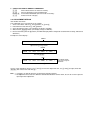
a. ENTERING SERVICE MODE
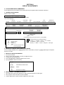
With the unit on standby
t [DISPLAY] t 5 t [VOL $+% ] t [POWER]
This operation sequence puts the unit into service mode.
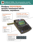
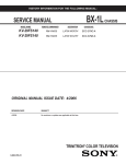
This screen display is:
item no.
in decimal
item name
service data
in decimal
NVM
NG
service command
field
frequency
channel no./
video input name
GEOM
006
HSIZ
031
x
SERVICE
60
S VIDEO 1
release ID
software
version
service data
in binary
reserved
for factory
color system
power on time
(decimal?)
0.69U
0001 1111
FF FF
NTSC3
65535
category
SUS01
Flash DCXO
111 11 11 1 7 11
FG
xy 111
Status Byte
#1 SSD
Status Byte
#2 SSD
000000
000000
VDSP_C Flag
CO_LOCKED
VDSP
Detected Stereo Type (Direct Value from CZ_ Stereo_Mode)
S : for Sony
A : Aiwa
U S : US/Latin/Taiwan
E U : Europe
G A : General Area
J P : Japan
0 1 : serial no. of the M/P release
for each destination
111
Needed for Nicam DCXO aligment Purpose
xy
Value of x = 0 - Unknown, 1 - BTSC, 2 - A2, 3 - NICAM,
4 - KOREAN, 5 - Japan, 6 - AV Stereo
Value of y = 0 - Mono, 1 - Stereo, 2 - Bilingual, 4 - SAP/Single
b. METHOD OF CANCELLATION FROM SERVICE MODE
Set the standby condition (Press [POWER] button on the commander), then press [POWER] button again, hereupon it
becomes TV mode.
c. METHOD OF WRITE INTO MEMORY
1.
2.
3.
4.
5.
Set to Service Mode.
Press 1 (UP) and 4 (DOWN), to select the adjustment item.
Change item by pressing 3, 6.
Press [MUTING] button to indicate WRITE on the screen.
Press - button to write into memory.
1, 4
r
3, 6
r
[MUTING]
r
-
Select the adjustment item.
Raise/lower the data value.
Writes.
Executes the writing.
d. MEMORY WRITE CONFIRMATION METHOD
1. After adjustment, pull out the plug from AC outlet, and then plug into AC outlet again.
2. Turn the power switch ON and set to Service Mode.
3. Call the adjusted items again to confirm adjustments were made.
e. OTHER FUNCTION VIA REMOTE COMMANDER
7, 8, Display, 2, 5
All the data becomes the values in memory.
All user control goes to the standard state.
Service data initialization (Be sure not to use usually.)
Select Device or Category
3-2. ADJUSTMENT METHOD
Item Number 000 HPOS
This explanation uses H POSITION as an example.
1. Select "000 HPOS" with the 1 and 4 buttons, or 2 and 5.
2. Raise/lower the data with the 3 and 6 buttons.
3. Select the optimum state. (The standard is IF for PAL reception.)
4. Write with the [MUTING] button. (The display changes to WRITE.)
5. Execute the writing with the - button. (The WRITE display will be changed to red color while excuting, and back to
SERVICE.)
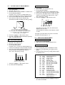
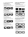
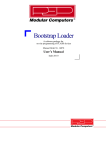
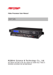
Example on screen display :GREEN
GEOM
000
HPOS
039
SERVICE
50 VIDEO 1
Adjusted with [3] and [6] buttons.
GREEN
GEOM
000
HPOS
039
WRITE
50
VIDEO
1
50
VIDEO
1
write with [MUTING].
RED
GEOM
000
HPOS
039
WRITE
The WRITE display
then returns to green
SERVICE
Write executed with [0].
Use the same method for all Items. Use 1 and 4 to select the adjustment item, use 3 and 6 to adjust, write with
[MUTING], then execute the write with -.
Note : 1. In [WRITE], the data for all items are written into memory together.
2. For adjustment items that have different standard data between 50Hz or 60Hz, be sure to use the respective
input signal after adjustment.
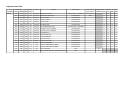
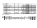
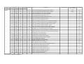
Adjustment Item Table
TVJ
Category
GEOM
Functionality
Init.
Range
DATA
Function
Table & Note
Device Name
NVM Address / Initial Value (Detailed)
No.
Name
Dec
Dec
000
HPOS
031
063
ADJUST
Horizontal Shift (HS)
001
HPAR
031
063
ADJUST
Horizontal Parallelogram
002
HBOW
031
063
ADJUST
Horizontal Bow
50/60/w50/w60
31
31
31
31
003
VLIN
031
063
ADJUST
Vertical Linearity
50/60/w50/w60
31
31
31
31
004
VSCR
031
063
ADJUST
Vertical Scroll
50/60/w50/w60
31
31
31
31
005
HSIZ
031
063
ADJUST
EW Width (EW)
50/60/w50/w60
25
25
25
25
006
EWPW
031
063
ADJUST
EW Parabola/Width (PW)
50/60/w50/w60 (+JPN RGB)
31
31
31
31
007
UCOP
017
063
ADJUST
EW Upper Corner Parabola
50/60/w50/w60
31
31
31
31
008
LCOP
017
063
ADJUST
EW Lower Corner Parabola
50/60/w50/w60
31
31
31
31
009
EWTZ
031
063
ADJUST
EW Trapezium
50/60/w50/w60
31
31
31
31
010
VSLP
031
063
ADJUST
Vertical Slope (VS)
50/60/w50/w60
31
31
31
31
011
VSIZ
015
063
ADJUST
Vertical Amplitude
50/60/w50/w60
15
15
15
15
012
SCOR
014
063
ADJUST
S-Correction (SC)
50/60/w50/w60
25
25
25
25
013
VPOS
031
063
ADJUST
Vertical Shift (VSH)
50/60/w50/w60
31
31
31
31
014
HBL
000
001
FIX
RGB Blanking Mode
50/60/w50/w60
01
01
01
01
(Slave Address)
Common
50
60
w50
w60
50/60/w50/w60 (+JPN RGB)
TV-Processor
42
42
42
42
50/60/w50/w60
(8Ah)
31
31
31
31
015
WBF
007
015
FIX
Timing of Wide Blanking (WBF)
50/60/w50/w60
07
07
07
07
016
WBR
007
015
FIX
Timing of Wide Blanking (WBR)
50/60/w50/w60
10
10
10
10
017
SBL
000
001
FIX
Service Blanking
none
00
018
COPY
000
001
FIX
Copy the GEO data to all 50/60Hz NVM area
none
00
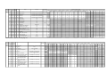
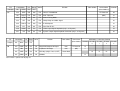
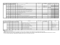
TVJ
Functionality
Init.
Range
Category
No.
Name
Dec
Dec
WHBL
000
BKOR
031
063
ADJUST Black Level Offset R
col temp (HIGH/LOW/Normal)*(UV/RGB/Others)
TV-Processor
31
31
31
31
31
001
BKOG
031
063
ADJUST Black Level Offset G
col temp (HIGH/LOW/Normal)*(UV/RGB/Others)
(8Ah)
31
31
31
31
31
002
RDRV
037
063
White Point R
col temp (HIGH/LOW/Normal)*(UV/RGB/Others)
TV-Pro (8AH)
37
37
37
37
37
DATA
Function
Table & Note
Device Name
(Slave Address)
FIX
NVM Address / Initial Value (Detailed)
Common
Col Temp
(HIGH other)
Col Temp
(LOW other)
Col Temp
(NORM other)
Col Temp
(HIGH YUV)
Col Temp
(LOW YUV)
Col Temp
(NORMAL YUV)
Col Temp
(HIGH RGB)
Col Temp
(LOW RGB)
Col Temp
(NORM RGB)
31
31
31
31
31
31
31
31
37
37
37
37
003
GDRV
037
063
ADJUST White Point G
col temp (HIGH/LOW/Normal)*(UV/RGB/Others)
31
31
31
31
31
31
31
31
31
004
BDRV
037
063
ADJUST White Point B
col temp (HIGH/LOW/Normal)*(UV/RGB/Others)
31
31
31
31
31
31
31
31
31
005
LPG
000
001
FIX
RGB Gain Preset
none
01
**
006
PGR
031
127
FIX
Preset Gain R (PGR)
none
007
PGG
031
127
FIX
Preset Gain G (PGG)
none
**
008
PGB
031
127
FIX
Preset Gain B (PGB)
none
**
FIX
Preset Gain Offset
009
GNOF
000
015
010
SBRT
031
063
011
SBRO
000
003
none
ADJUST Sub-Brightness
FIX
Sub-Brightness Offset (Intelligent Pic)
CCC loop
Others
RGB
YUV
31
31
31
Pic mode
0
Pic mode
1
Pic mode
2
Pic mode
3
00
01
02
01
15
Others/RGB/YUV
none
00
012
EGL
000
001
FIX
Enable Gain Loop in CCC System
none
01
013
SGL
000
003
FIX
Selection of High Current in CCC System
none
00
014
AKB
000
001
FIX
Black Current Stabilization
none
00
015
CBS
000
001
FIX
Control Sequence of Beam Current Limiting
none
00
016
RGBB
000
003
FIX
RGB Blanking
none
00
017
BLBG
000
001
FIX
Blanking of Blue & Green Output
none
00
018
OFB
000
001
FIX
Black Level Offset Blue
none
01
019
NSBR
000
015
FIX
Non Standard Brightness Offset
none
05
020
WBP
000
003
FIX
Color Temp Setting (0:High, 1:Normal, 2,3:Low)
Picture Mode
Item remarks ** please refer to page 23
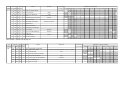
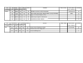
TVJ
Functionality
Init. Range
DATA
Function
Table & Note
Device Name
NVM Address / Initial Value (Detailed)
(Slave Address) Common YUV 50pal 50pal 50secam 50secam 60TV 60Video 50YUV 60YUV 50RGB 60RGB Pic mode Pic mode Pic mode Pic mode Dynamic*Eco
(TV) (Video) (TV) (Video)
0
1
2
3
std (Jpn)
Category
No.
Name Dec
Dec
SADJ
000
PMAX 063
063
ADJUST Picture Maximum
001
SHUE 007
015
ADJUST Sub-Hue
002
SSHP 015
063
FIX
Sub-Sharpness
003
SSHO 000
003
FIX
Sub-Sharpness Offset (Intelligent Pic)
004
SCOL 031
063
005
SCOO 000
ADJUST Sub-Color
(TV / Video)*(Normal / Wide) / <Normal / Wide> (+JPN RGB)
TV-Processor
TV / Video
**
TV / Video / YUV (+JPN RGB)
none
02
50pal(tv)/50pal(video)/50secam(tv)/50secam(video)/
60TV/60video/50YUV/60YUV/50RGB/60RGB
none
31
31
31
31
31
31
31
31
31
31
003
FIX
Sub-Color Offset (Intelligent Pic)
006
PIC
031
127
FIX
Picture Control [GA:0-100(valid), >100(invalid);
Others:0-63(valid); ignore bit 6(invalid)]
Picture Model(GA: Personal = User Reset Data)
02
100
80
95
100
007
COL
031
127
FIX
Color Control [GA:0-100(valid), >100(invalid);
Others:0-63(valid); ignore bit 6(invalid)]
Picture Model(GA: Personal = User Reset Data)
56
50
40
50
008
BRT
031
127
FIX
Brightness Control [GA:0-100(valid),
>100(invalid); Others:0-63(valid); ignore bit
6(invalid)]
Picture Model(GA: Personal = User Reset Data)
50
50
60
50
009
HUE
031
127
FIX
Hue Control [GA:0-100(valid), >100(invalid);
Others:0-63(valid); ignore bit 6(invalid)]
Picture Model(GA: Personal = User Reset Data)
50
50
50
50
010
SHP
031
127
FIX
Sharpness Control [GA:0-100(valid),
>100(invalid); Others:0-63(valid); ignore bit
6(invalid)]
Picture Model(GA: Personal = User Reset Data)
60
50
50
50
Dynamic*Eco Standard*Eco Standard*Eco Eco std Eco much TV Video TV Video AVM AV Wide
much (Jpn)
std (Jpn)
much (Jpn) (Jpn)
(Jpn)
Wide Wide (Jpn) (Jpn)
37
37
07
07
**
**
37
37
37
37
TVJ
Functionality
Init. Range DATA
Category
No.
Name
Dec
Dec
YC
000
PFRQ
000
003
FIX
Peaking Center Frequency and Delay
Function
Table & Note
Device Name
NVM Address / Initial Value (Detailed)
(Slave Address) Common Others RGB
TV-Processor
YUV
PAL(TV) NTSC(TV) SECAM(TV) PAL(Video) NTSC(Video) SECAM(Video) S-INPUT SECAM NTSC TV
**
001
RPA
####
003
FIX
Ratio Pre & Over Shoot
TV/other
02
02
002
RPO
002
0 03
FIX
Ratio of Positive & Negative Peaks
TV/other
02
02
003
YDLY
0 12
015
FIX
Y-Delay
004
CMAT
000
003
FIX
PAL-SECAM or NTSC (Japan/USA) Matrix
005
ACL
001
001
FIX
Automatic Color Limiting
006
CB
000
001
FIX
Chroma Bandpass Center Frequency
(PAL/NTSC/SECAM)*(TV/VIDEO)+YUV/S-INPUT
**
(JPN RGB)
00
valid only with TV (*Video:0 fix)
01
**
**
**
**
**
**
**
01
007
SB O
001
003
FIX
SECAM Black Offset
00
008
CHSE
001
003
FIX
PAL/NTSC Ident Sensitivity
02
009
CLO
000
001
FIX
Center Frequency of Cloche(Bell) Filter
00
010
CTRP
000
001
FIX
Chroma Trap Mode
011
BPS
000
001
FIX
Bypass of Chroma Base-band Delay Line
012
FCO
000
001
FIX
Forced Color On
013
TINT
031
063
FIX
Base-Band Tint Control
014
TUV
000
001
FIX
Tint Control on UV Signals
SECAM/others
00
NTSC/others
**
01
**
00
YUV/others
31
31
00
Item remarks ** please refer to page 23
TVJ
Functionality
Init.
Range
Category
No.
Name
Dec
Dec
SYNC
000
SYS
000
001
FIX
Synchronization on YSYNC Input
001
FO
000
003
FIX
Phase 1 Time Constant
002
VID
000
001
FI X
Video Ident Mode
DATA
Function
Table & Note
Device Name
(Slave Address)
NVM Address / Initial Value (Detailed)
Common
50
60
00
00
00
00
others
YUV
TV
Video
Teletext
TV-ip
No signal
03
03
01
00
00
00
TV IP ON/TV IP OFF/Video/Teletext/Auto Tuning or No signal(RF)
50/60
003
FSL
000
001
FIX
Forced Slicing Level for Vertical Sync
004
SSL
000
001
FIX
Slicing Level Sync Separator
005
SVID
001
007
FIX
Source Selection for Video Identification
006
FORF
000
003
FIX
Forced Field Frequency
03
007
MVK
000
001
FIX
Macro Vision Keying
01
00
50/60
YUV/Others
00
07
TVJ
Category
PICT
Functionality
Init.
Range
DATA
Function
Table & Note
Device Name
(Slave Address)
No.
Name
Dec
Dec
000
CADL
007
015
FIX
Cathode Drive Level
NVM Address / Initial Value (Detailed)
Common Others
RGB
Live
TV
TV
Video Video ColorTemp ColorTemp
Color
Color Temp
(Dyn) (Others) (Dyn) (Others) (HIGH)
(Others) Temp(LOW) (NORMAL)
00
**
001
CFA
000
003
FIX
Comb Filter Mode
002
SOC
002
003
FIX
Soft Clipping Level
003
PWL
001
001
FIX
Peak White Limiting Switch
01
004
WHTL
006
015
FIX
Peak White Limiting
00
005
GAM
001
001
FIX
Gamma
006
WTS
001
003
FIX
Gamma Control and White Stretch
007
TFR
000
001
FIX
008
COR
003
003
FIX
009
CORO
000
001
FIX
Coring Offset (Intelligent Pic)
010
BKS
003
003
FIX
Black Stretch
011
AAS
001
001
FIX
Black Area to Switch off the Black Stretch
00
012
DSK
000
001
FIX
Dynamic Skin Control
00
(8Ah)
00
00
Live/Others
01
DC Transfer Ratio of Luminance Signal
Live/Others (+JPN RGB)
01
Coring
(TV/Video)*(Dyna/others)
013
BLS
000
001
FIX
Blue Stretch
NBLS
000
001
FIX
Operation Blue Stretch Circuit
015
NRR
000
001
FIX
Non Red Reduction
00
01
00
00
00
00
00
RGB/others
014
01
02
02
col temp (HIGH/OTHERS)
00
00
00
col temp (HIGH/LOW/NORMAL)
01
01
01
Item remarks ** please refer to page 23
TVJ
Category
SW
Functionality
Init.
Range
No.
Name
Dec
Dec
000
CV2
000
001
FIX
CVBS2 Input Signal Selection
001
SVO
001
003
FIX
Function of IFVO/SVO/CVBSI Pin @ 48
002
DFL
000
001
FIX
Flash Protection
DATA
Function
Table & Note
Device Name
(Slave Address)
NVM Address / Initial Value (Detailed)
Common
YUV
TV
Video
02
01
01
00
TV/Video/YUV
00
TVJ
Category
V IF
TVJ
Functionality
Init.
Range
No.
Name
Dec
Dec
000
OIFD
036
063
FIX
Offset IF Demodulator
001
AGCT
031
063
FIX
AGC Take-over
002
STM
000
001
FIX
Search Tuning Mode
01
003
GD
000
001
FIX
Group Delay on CVBS1 Signal
00
004
AGCS
001
003
FIX
IF AGC Speed
01
005
FFI
000
001
FIX
Fast Filter IF PLL
00
006
OAMP
003
003
FIX
Video Output Signal Amplitude (only L & L'System)
03
007
VAI
000
001
FIX
System I Output Signal Amplitude Correction (only L & L'System)
00
DATA
Function
Device Name
Common
(Slave Address)
Functionality
Init.
Range
Category
No.
Name
Dec
Dec
VM
000
RGBD
003
007
FIX
Delayof RGB Output to VM Output
001
VMA
003
003
FIX
Amplitude of VM Output
002
VMAP
002
003
FIX
VM setting (0:High, 1:Low, 2,3:OFF)
003
VMMO
003
003
FIX
VM Mode
Item remarks ** please refer to page 23
Table & Note
DATA
Function
Table & Note
Device Name
TV-Processor
36
(8Ah)
31
NVM Address / Initial Value (Detailed)
(Slave Address)
Common
none
TV-Processor
02
none
(8Ah)
**
Picture Mode
01
Pic mode
0
Pic mode
1
Piv mode
2
Pic mode
3
00
01
02
00
TVJ
Category
SDEM
TVJ
Category
TXT
Functionality
Init.
Range
No.
Name
Dec
Dec
000
FMWS
000
003
FIX
Window Selection for FM Demodulator
001
QSS
001
001
FIX
Quasi Split Sound (QSS) Amplifier Mode (except GA Model)
002
BPB
000
001
FIX
Bypass of Sound Bandpass Filter
00
003
AMLO
000
001
FIX
Audio Output Signal for AM Sound
00
004
HPVC
000
001
FIX
Head Phone Volume Control
00
DATA
Function
Table & Note
Device Name
Common
(Slave Address)
TV-Processor
02
(8Ah)
01
Functionality
Init.
Range
No.
Name
Dec
Dec
000
TXV
039
063
FIX
Teletext Vertical Position for Philips
001
THD
005
127
FIX
Teletext H-sunc Active Edge Shift
05
002
TBR
004
015
FIX
Teletext RGB Brightness
11
DATA
Function
Table & Note
Device Name
Common
(Slave Address)
Text Decoder
39
TVJ
Functionality
Init.
Range
Category
No.
Name
Dec
Dec
SDSP
000
AVM
002
007
FIX
AVL Mode
SSD
02
(B0h)
09
DATA
Function
Table & Note
Device Name
(Slave Address)
NVM Address / Initial Value (Detailed)
Common
001
AVV
005
015
FIX
AVL Reference Level
002
BBL
000
015
FIX
BBE Contour
**
003
BBH
000
015
FIX
BBE Process
**
004
BBLW
000
015
FIX
BBE Contour Offset
005
SVOF
000
015
FIX
Surround /Effect Mode Volume Offset
006
IVOF
000
007
FIX
Master Volume Positive Offset
TV
Video
Off
SRS/WOW
Trusurround
Istereo
Imono
00
07
00
02
00
05
03
**
Off(SRS/WOW)/Trusurround/Istereo/Imono
06
007
EVOF
000
007
FIX
Master Volume Negative Offset
06
008
LAD
000
031
FIX
Decoder Level Adjust
05
009
LAM
000
031
FIX
Mono Level Adjust
05
010
LAN
000
031
FIX
Nicam Level Adjust
17
011
LAS
000
031
FIX
SAP Level Adjust
08
012
LAA
000
031
FIX
ADC Level Adjust
013
SEF
003
007
FIX
Incredible Mono/Stereo Effect
014
A1L
000
255
FIX
AUX1 Volume Left
00
00
Tv/Video(Non Euro)I TV-L/TV-non L/Video
00
Istereo/Imono
015
A1R
000
255
FIX
AUX1 Volume Right
016
BAS
008
015
FIX
Main Bass Offset
**
017
TRE
008
015
FIX
Main Treble Offset
**
**
018
EQ1
008
015
FIX
Equalizer Main Channel Band (100 Hz) Offset
019
EQ2
008
015
FIX
Equalizer Main Channel Band (300 Hz) Offset
**
020
EQ3
008
015
FIX
Equalizer Main Channel Band (1000 Hz) Offset
**
**
021
EQ4
008
015
FIX
Equalizer Main Channel Band (3000 Hz) Offset
022
EQ5
008
015
FIX
Equalizer Main Channel Band (8000 Hz) Offset
**
023
BFCT
005
007
FIX
DBE, DUB and BBE Control
**
024
SCEN
001
015
FIX
SRS3D Center Control
04
025
SSPA
000
015
FIX
SRS3D Space Control
01
026
BBHW
000
015
FIX
BBE process offset in WOW mode
**
027
STRE
002
007
FIX
Treble Offset for surround mode
**
028
BBHT
000
015
FIX
BBE Offset in TV mode
00
029
DWA
000
000
FIX
DWA
00
030
TTRE
002
007
FIX
Treble Offset in TV Mode
02
Item remarks ** please refer to page 23
TV-L(Euro)
00
00
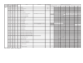
TVJ
Category
SDEC
Functionality
Init.
Range
No.
Name
Dec
Dec
000
MPTU
003
015
DATA
FIX
Function
Table & Note
Device Name
(Slave Address)
Common
Upper Threshold for MPX pilot detection (BTSC)
SSD
02
(B0h)
001
MPTL
009
015
FIX
Lower Threshold for MPX pilot detection (BTSC)
002
SPTU
003
015
FIX
Upper Threshold for SAP carrier detection
08
003
SPTL
006
015
FIX
Lower Threshold for SAP carrier detection
15
05
004
C1TH
000
031
FIX
Normal Threshold for detection of SC1
00
005
C1AP
000
031
FIX
Auto Program Threshold for detection of SC1
00
006
SPTH
000
031
FIX
Noise Threshold for automute of SAP
00
007
SPHY
004
015
FIX
Hysteresis size for automute of SAP
03
008
FMTH
000
031
FIX
Noise Threshold for automute of SC2 in FM A2 standard
18
009
FMHY
004
015
FIX
Hysteresis size for automute of SC2 in FM A2 standard
07
00
010
BTTH
000
03 1
FIX
Noise Threshold for automute of BTSC stereo carrier
011
BTHY
004
015
FIX
Hysteresis size for automute of BTSC stereo
03
012
EJTH
000
031
FIX
Noise Threshold for automute of EIAJ FM subcarrier
00
04
013
EJHY
004
015
FIX
Hysteresis size for automute of EIAJ FM subcarrier
014
ONLY
000
00 1
FIX
Reproduce only related NICAM on DEC output
00
015
EXAM
000
001
FIX
Fall back source in case of automute in standard L (DDEP)
00
016
NIMT
000
001
FIX
NICAM auto mute function depend on bit error rate (DDEP)
00
017
NILE
100
255
FIX
NICAM lower error limit (DDEP)
50
018
NIUE
200
255
FIX
NICAM upper error limit (DDEP)
200
019
EPMD
001
003
FIX
DEMDEC Easy Programming (DDEP)
020
STDS
019
031
FIX
Bits multiplexed for ASD and SSS modes
31
021
OVMA
001
001
FIX
FM overmodulation adaption
00
022
FLBW
000
003
FIX
FM/AM demodulator filter bandwidth
03
023
IDMD
000
003
FIX
FM ident speed in SSS mode
00
024
FPAL
000
001
FIX
Line fequency for BTSC decoding
00
025
OVMT
001
002
FIX
Overmodulation level threshold relative to nominal
03
02
026
DCXI
000
001
FIX
NICAM DCXO Scaling Control Inverter
**
027
DCXG
000
007
FIX
NICAM DCXO Scaling Control Gain
**
028
DCLL
011
015
FIX
NICAM DCXO Scaling Control Limit (L)
00
029
DCLH
000
031
FIX
NICAM DCXO Scaling Control Limit (H)
**
030
IDEU
001
003
FIX
IDMOD setting for European A2 STD
00
031
IDKR
001
003
FIX
IDMOD setting for Korean M STD
00
032
IDJP
001
003
FIX
IDMOD setting for EIAJ STD
01
Item remarks ** please refer to page 23
TVJ
Category
OPTM
TVJ
Category
OPTB
Functionality
Init.
Range
No.
Name
Dec
Dec
000
ASHT
006
007
DATA
FIX
Function
Table & Note
Device Name
(Slave Address)
Auto shut off timer (data * 5 min)
NVM Address / Initial Value (Detailed)
Common
001
OSDB
000
015
FIX
OSD brightness
MMR/Micro 60h
00
002
OSDH
005
015
FIX
OSD Horizontal Position
MMR/Micro 60h
05
003
OSDV
037
063
FIX
OSD Vertical Position
004
MUTE
000
001
FIX
No Signal Mute Switch (1=enabled)
00
04
50 / 60
MMR/Micro 60h
005
RFUL
015
015
FIX
RF Signal Change Counter after Unlocked (Disable when 0fh)
006
RFLK
015
015
FIX
RF Signal Change Counter after Locked (Disable when 0fh)
00
007
AVUL
015
015
FIX
AV Signal Change Counter after Unlocked (Disable when 0Fh)
04
00
008
AVLK
015
015
FIX
AV Signal Change Counter after Locked (Disable when 0Fh)
009
LANG
000
003
FIX
OSD language shipping condition
010
HTXT
000
001
FIX
Sync seperator sw
011
CMSS
000
001
FIX
Sync sw
012
DCXO
060
295
FIX
DCXO Value
63
31
00
TV-Processor(8A)
01
SFR/Micro 60h/DSP
59
013
EXBL
000
015
FIX
Extended Blanking Timer to Eliminate White Noise
07
TSYS
000
003
FIX
Memorize TV Sys in NVM at Test Reset [0:B/G, 1:I, 2:M, 3:D/K] (GA Model)
00
015
TVOU
001
001
FIX
TV OUT mute condition 0:Always mute off, 1:mute without signal
00
Functionality
Init.
Range
No.
Dec
Dec
Name
60
00
TV-Processor(8A)
014
DATA
50
00
Function
Table & Note
Device Name
(Slave Address)
Common
Note
000
IALL
000
001
FIX
Standard Write Switch (not memorized in NVM)
001
OPB1
000
255
FIX
Option 1 (System related)
*****
For remark *****
002
OPB2
000
255
FIX
Option 2 (Video Signal related)
*****
Refer to option
00
003
OPB3
000
255
FIX
Option 3 (Stereo Decoding related)
*****
Bit setting on
004
OPB4
000
255
FIX
Option 4 (Miscellaneous)
*****
Page 24 - 26
005
OPB5
000
255
FIX
Option 5 (Miscellaneous)
*****
006
OPB6
000
255
FIX
Option 6 (OSD Language related)
*****
NOTE
•
shaded items are no data.
• Standard data listed on the Adjustment Item Table are reference values, therefore it may be different for each model and for each mode.
• Note for Different Data Those are the standard data values written on the microprocessor. Therefore, the data values of the modes and stored respectively in the memory.
In case of a device replacement, adjustment by rewriting the data value is necessary for some items.
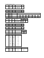
Data Variant depend on models
Category
No
Name
Model
Data
WHBL
006
007
008
PGR
PGG
PGB
Without VM
Without VM
Without VM
61
61
61
Category
No
Name
Model
Data
VM
001
VMA
Without VM
00
Category
YC
Category
SADJ
No Name
003 YDLY
No
002
Model
Table
Non-Comb Model
Name
SSHP
PAL
(TV)
NTSC
(TV)
SECAM
(TV)
PAL
(VIDEO)
NTSC
(VIDEO)
SECAM
(VIDEO)
YUV
02
02
10
2
2
2
09
Model
21"Non-Comb models &
All 14" models
TV
Table
Video
YUV
35
38
35
Category
No
Name
Model
Data
PICT
000
PFRQ
Non-Comb models
01
Category
No
Name
Model
Data
YC
000
PFRQ
Non-Comb models
00
Category
No
Name
Model
YC
011
BPS
Non-Comb models
Category
No
Name
SDSP
002
003
004
016
017
018
019
020
021
022
023
026
027
BBL
BBH
BBLW
BAS
TRE
EQ1
EQ2
EQ3
EQ4
EQ5
BFCT
BBHW
STRE
00
00
06
13
14
09
09
09
10
11
00
00
01
Category
No
Name
Stereo models
SDEC
26
027
029
DCXI
DCXG
DCLH
01
03
06
Table
NTSC Others
00
00
Non-stereo models
00
00
00
S-Input
09
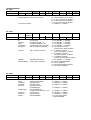
ITEM INFORMATION
No. OPB1
Item
KV-BT21M90
Speed Search
0
1
M/N(US)
L’
M
B/G
I
D/K
DEC
0
0
1
1
1
1
79
SPEED SEARCH (Time of speed search)
00 = disabled (original cycle speed)
01 = 4 time speed from the original
10 = 6 time speed from the original
11 = 8 time speed from the original
0 = disabled, 1 = enabled
TV System Selection
No. OPB2
Item
KV-BT21M90
D1(JPN)
AV Multi/ Component Composite (SCART)
PAM(GA)
0
0
0
1
0
D1
AV Multi/
PAM
Component
Composite
(D1 Terminal)
(AV Multi Terminal) - JP
Portable Audio Mode - GA
(Component [YCbCr] Terminals)
(No. of Composite Terminals)
(SCART)
(No. of SCART Terminals)
SECAM
Color decoding
(SECAM Color System)
(Color Crystal Selection)
SECAM
1
Color Decording
0
0
DEC
20
0 = not available, 1 = available
0 = not available, 1 = available
0 = not available, 1 = available
0 = not available, 1 = available
00 = no composite terminal
(Euro:no Scart) BX1L:No Video
01 = 1 composite terminal
(Euro:1 Scart) BX1L:2 Video in
10 = 2 composite terminals
(Euro:2 Scart) BX1L:3 Video in
11 = 3 composite terminals
(Euro:no terminal) BX1L:4 Video in
0 = not available, 1 = available
00 = PAL/NTSC/SECAM (Multi)
01 = NTSC (3.58MHz)
10 = PAL/NTSC/SECAM (4.43MHz)
11 = PAL/NTSC (Tri-Norma)
No. OPB3
Item
KV-BT21M90
HDEV
NICAM ST NICAM BI
0
HDEV
NICAM ST
NICAM BI
A2 ST/BI
Thai Bilingual
JP/US ST
Korean ST
MONO
1
1
A2 ST
1
Thai Bilingual JP/US ST Korean ST
0
(High Deviation Mode)
(NICAM Stereo)
(NICAM Stereo)
(A2 [West German]
Stereo/Bilingual)
(A2 [Thai] Bilingual)
or Force SAP if JP/US ST is act
(JP/US Stereo)
(Korean Stereo)
(Monaural Model)
0
MONO
DEC
0
112
0
0 = disabled, 1 = enabled
0 = disabled, 1 = enabled
0 = disabled, 1 = enabled
0 = disabled, 1 = enabled
0 = disabled, 1 = enabled
0 = disabled, 1 = enabled
0 = disabled, 1 = enabled
0 = Stereo (SSD) Model
1 = Monuaral Model
No. OPB4
Item
KV-BT21M90
Firmware/
SMAT
1 spk
Models
VM
1
0
0
Equalizer Surround
0
0
Firmware
SMAT
1 spk Models
(SSD Firmware Downloading)
Surround Matrix
1 Speaker Models
VM
Equalizer
Surround
(Velocity Modulation)
(5-band Equalizer Model)
(US/GA Surround Selection)
V-Chip
(V-Chip Model)
TOP
TEXT
(Forced TOP)
(Teletext Model)
V-Chip
Top
Text
DEC
0
0
0
128
0 = disabled, 1 = enabled
0 = Active, 1 = Passive
0 = 2 or 3 Speaker Models,
1 = 1 speaker Models
0 = disabled, 1 = enabled
0 = Bass/Treble Model, 1 = Equalizer Model
0 = Off/Simulated/Surround
1 = Off/Simulated/WOW/TruSurround (US)
1 = Off/Simulated/SRS (3D) Surround (GA)
0 = Channel Block Model (no rating)
1 = Parental Control Model (rating)
0 = Auto Mode (TOP/FLOF), 1 = Forced TOP
0 = Non-Teletext Model, 1 = Teletext Model
No. OPB5
Item
KV-BT21M90
Full
No
Forced 60
Surround Surround
0
0
0
ASD
Tilt
IP Plus
IP
Wide
DEC
1
1
1
1
0
30
Full Surround
(Full Surround option)
No Surround
Forced 60
ASD
Tilt
IP Plus
IP
Wide
(No Surround Model)
(Forced 60Hz in no signal)
(Automatic Standard Detection)
(Tilt Correction/PIC Rotation)
(Intelligent Picture Plus)
(Intelligent Picture)
(Wide Mode/V-Compressed)
0 = Normal Surround Model
1 = Full Surround Model
(Off/simulated/surround/
SRS/WOW/TruSurround)
0 = Surround Model, 1 = Non-Surround Model
0 = 50Hz, 1 = 60Hz
0 = disabled, 1 = enabled
0 = disabled, 1 = enabled
0 = disabled, 1 = enabled
0 = disabled, 1 = enabled
0 = disabled, 1 = enabled
No. OPB6
Item
GA US
Latin
1
0
KV-BT21M90
Feature 2 Feature 1
0
1
GA US
(US Model Destination)
Latin
(US Model Latin Destination)
Feature 2
(Temporary for BX1L)
Feature 1
(Temporary for BX1L)
OSD Language Selection
(English always available except JP)
DEC
OSD Language Selection
0
0
0
0
136
0 = US/CANADA/Latin
1 = Taiwan/Korea/Philippine
(Wake-up timer enable)
(GA Surround Spec:OFF,
SIMULATED, SRS)
0 = US/CANADA (No Volume Figure Display)
1 = Latin (Volume Figure Display)
0 = Comb Not available
1 = Comb available
0 = PiP Not Available
1 = PiP available
US
01xx = French
0x1x = Spanish
0xx1 = Portuguese
US
(GA NTSC)
1x1x = Complicated Chinese
1xx1 = Korean
GA
EU
1xxx = Simplified Chinese
x1xx = Arabic
xx1x = Thai
xxx1 = Vietnamese
0000 = Destination ADE
0001 = Destination BL
0010 = Destination KR
0011 = Destination U
3-3.
PICTURE QUALITY ADJUSTMENTS
PMX/CONTRAST ADJUSTMENT
1.
2.
3.
4.
Select Video Mode.
Input PAL CB to TV set.
Set PICT 03 "PWL" to 00h and WHBL 21 "BLBG" to 01h.
Set the following condition:
PICTURE 100%, COLOR 0%, BRIGHTNESS 50%.
5. Connect an oscilloscope to pin 4 (R output) of CN004.
6. Set to Service Mode "PWL" to 00h, “BLBG” to 01h.
7. Select SADJ00 "PMX" with 1 and 4 of the
commander then adjust VR within spec with 3 and 6.
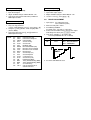
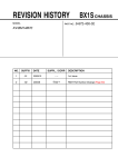
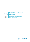
SUB HUE ADJUSTMENT
1. Select Video.
2. Input a NTSC 3.58 Color Bar to TV set.
3. Set the following condition:
PICTURE 100%, COLOR 50%, BRIGHTNESS 50%
4. Connect an oscilloscope to pin 2 (B output) of CN004.
5. Set to Service and adjust SADJ01 "SHUE" with 1
and 4 of commander then adjust to VB1 = VB2 =
VB3 = VB4 with 3 and 6.
6. Then press [MUTING] t - to write the data.
VB1
VR
Black
1.23 ± 0.03 Vp-p = for NTSC VM Models
1.46 ± 0.03 Vp-p = for 21" without VM Models
1.65 ± 0.03 Vp-p = with VM Models except NTSC models
1.10 ± 0.03 Vp-p = for 21" NTSC non VM Models
1.38 ± 0.03 Vp-p = for 14" Models
8. Then press [MUTING] t - to write the data
9. Set "PWL" and "BLBG" back to initial data repectively.
(PWL: 01h and BLGG: 00h)
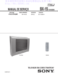
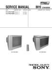
SUB COLOR ADJUSTMENT
1.
2.
3.
4.
Select Video and set Picture mode.
Input PAL 100% CB to TV set.
Set PICT 06 "WTS" to 00h.
Set the following condition:
PICTURE 100%, COLOR 50%, BRIGHTNESS 50%.
5. Connect an oscilloscope to pin 2 (B output) of CN004.
6. Select to Service Mode and adjust SADJ04 "SCOL"
with 1 and 4 of commander then adjust to
VB2 = VB3 = VB4 with 3 and 6.
VB1
The highest level of VB1, VB2, VB3, VB4 must be
aligned at the same time.
The ideal difference between VB2 and VB3 is within
±110mV.
For single system with NTSC 4.43 select TV channel
with NTSC 4.43 and repeat 4 t 6.
3-4.
DEFLECTION ADJUSTMENT
H-TRAPEZOID ADJUSTMENT
1. Receive cross hatch/dotsignal.
2. Adjust on to make H-Trapezoid distortion best.
NORMAL MODE (50Hz)
1. Set to Service Mode.
2. Input SPCB Signal (Select Video Mode for USA).
3. Using the 1 and 4 button select GEO (Service
Mode).
4. Rasie/lower data using the 3 and 6 buttons adjust
the following items:GEOM :
VB2 VB3 VB4
VB2 = VB3 = VB4
(Difference is within 70mV)
7. Then press [MUTING] t - to write the data.
8. Set "WTS" back to original data.
VB3 VB4
VB2
000
001
002
003
004
005
006
007
008
009
010
011
012
013
014
015
016
017
018
HPOS
HPAR
HBOW
VLIN
VSCR
HSIZ
EWPW
UCOP
LCOP
EWTZ
VSLP
VSIZ
SCOR
VPOS
HBL
WBF
WBR
SBL
COPY
Horizontal Shift (HS)
Horizontal Parallelogram
Horizontal Bow
Vertical Linearity
Vertical Scroll
EW Width (EW)
EW Parabola/Width (PW)
EW Upper Corner Parabola
EW Lower Corner Parabola
EW Trapezium
Vertical Slope (VS)
Vertical Amplitude
S-Correction (SC)
Vertical Shift (VSH)
RGB Blanking Mode
Timing of Wide Blanking (WBF)
Timing of Wide Blanking (WBR)
Service Blanking
Copy the GEO data to all
50/60Hz NVM area
5. Write into memory by pressing [MUTING] then - on
the remote commander.
WIDE MODE (50Hz)
WIDE MODE (60Hz)
(V-Compression Adjustment)
1. Input SPCB signal.
2. Adjust condition change to WIDE MODE : ON
3. Copy (Item from normal mode 50Hz) all Normal
Mode adjusted data.
(V-Compression Adjustment)
1. Input mono scope signal.
2. Adjust condition change to WIDE MODE : ON
3. "COPY" is set to 1, then [MUTE] + -
3-5.
NORMAL MODE (60Hz)
1. Input signal
1. Input 525/60Hz signal.
2. They can copy 50Hz first.
("COPY" under GEOM is set to 1, then [MUTE] + -)
3. Using the 1 and 4 button, select category GEO
(Service Mode).
4. Raise/lower data using the 3 and 6 buttons to
obtain optimum image.
GEOM :
000
001
002
003
004
005
006
007
008
009
010
011
012
013
014
015
016
017
018
HPOS
HPAR
HBOW
VLIN
VSCR
HSIZ
EWPW
UCOP
LCOP
EWTZ
VSLP
VSIZ
SCOR
VPOS
HBL
WBF
WBR
SBL
COPY
DRIVE ADJUSTMENT
Horizontal Shift (HS)
Horizontal Parallelogram
Horizontal Bow
Vertical Linearity
Vertical Scroll
EW Width (EW)
EW Parabola/Width (PW)
EW Upper Corner Parabola
EW Lower Corner Parabola
EW Trapezium
Vertical Slope (VS)
Vertical Amplitude
S-Correction (SC)
Vertical Shift (VSH)
RGB Blanking Mode
Timing of Wide Blanking (WBF)
Timing of Wide Blanking (WBR)
Service Blanking
Copy the GEO data to all
50/60Hz NVM area
2.
3.
4.
5.
70% Color Bar (USA)
100% Color Bar (Other)
Make sure only red is active.
Set following condition :PICTURE 100%, COLOR 0%, Other 50%
Select SADJ00 "PMAX" with 1 and 4 then adjust
until voltage in R out X gain [recorded] = SPEC
Then press [MUTING] t - to write data.
X±2VDC (R Cathode on C or CV board)
Model
14”
21”
GA
83.0
88.0 - Non VM Models
99.0 - VM Models
6. Set VIDP 36 BLBG back to 00.
3-6.
PICTURE DISTORTION ADJUSTMENT
H. CENTER ADJUSTMENT (HPOS)
1. Input Monoscope signal.
2. Activate the Service Adjustment Mode.
3. Select the HPOS item with 1 and 4.
4. Adjust the value of HPOS with 3 and 6 for the best
vertical center.
5. Press [MUTING] then - to save into the memory.
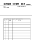
V. LINEARITY (VLIN), V. CORRECTION (SCOR), PIN
AMP (EWPW), AND HORIZONTAL TRAPEZOID
(EWTZ) ADJUSTMENTS
1. Input Monoscope signal.
2. Activate the Service Adjustment Mode.
3. Select VLIN, SCOR, EWPW, and EWTZ with 1 and
4.
4. Adjust with 3 and 6 for the best horizontal size.
5. Press [MUTING] then - to save into the memory.
V LINEARITY (VLIN)
H. SIZE ADJUSTMENT (HSIZ)
1. Input Monoscope signal.
2. Activate the Service Adjustment Mode.
3. Select HSIZ with 1 and 4.
4. Adjust with 3 and 6 for the best horizontal size.
5. Press [MUTING] then - to save into the memory.
V CORRECTION (SCOR)
PIN AMP (EWPW)
HORIZONTAL TRAPEZOID (EWTZ)
V. SIZE ADJUSTMENT (VSIZ)
1.
2.
3.
4.
Input Monoscope signal.
Activate the Service Adjustment Mode.
Select the VSIZ item with 1 and 4.
Adjust value of VPOS with 3 and 6 for the best
vertical center.
5. Press [MUTING] then - to save into the memory.
V. CENTER ADJUSTMENT (VPOS)
Input Monoscope signal.
Activate the Service Adjustment Mode.
Select the VPOS item with 1 and 4.
Adjust value of VPOS with 3 and 6 for the best
vertical center.
5. Press [MUTING] then - to save into the memory.
V. ANGLE (HPAR), H. BOW (HBOW), UPPER PIN
(UCOP) AND LOW PIN (LCOP) ADJUSTMENTS
1. Input Monoscope signal.
2. Activate the Service Adjustment Mode.
3. Select HPAR, HBOW, UCOP, and LCOP with 1 and
4.
4. Adjust with 3 and 6 for the best picture.
5. Press [MUTING] then - to save into the memory.
V ANGLE (HPAR)
1.
2.
3.
4.
V BOW (HBOW)
UPPER PIN (UCOP)
LOW PIN (LCOP)