1
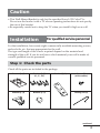
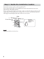
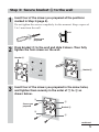
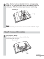
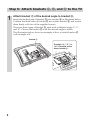
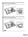
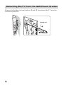
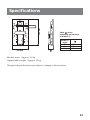
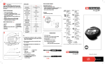
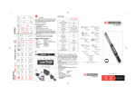
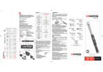
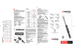
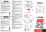
4-095-518-E1 (2)
Wall-Mount Bracket
Operating Instructions
• This Wall-Mount Bracket is designed for use with the Sony KLV-SG21M1
LCD Color TV.
SU-W210
© 2004 Sony Corporation
Thank you for purchasing this product.
For Customers
Sufficient expertise is required for installing this product, especially to
assure the strength of the wall. Be sure to entrust the attachment of this
product on the wall (Step 1 to Step 3 in “Installation”) to qualified service
personnel and pay adequate attention to safety during the installation. We
are not liable for any damage or injury caused by mishandling or improper
installation.
WARNING
To avoid risk of serious injury or damage to the TV caused by dropping it,
observe the following precautions.
• Do not hang from the TV or the Wall-Mount Bracket installed on the wall.
• Be careful not to trap the AC power adaptor cord of the TV when you secure
the TV to the Wall-Mount Bracket.
• Follow the installation procedures and installation direction described in this
manual.
For a safety installation, consult qualified service personnel.
• Before installing, confirm that the wall has sufficient strength to support the
TV and the Wall-Mount Bracket. The installation location should be a flat,
perpendicular wall with a reinforcing material inside.
• Do not apply a weight other than the TV to the Wall-Mount Bracket installed
on the wall.
• Do not disassemble, modify or change the parts of the Wall-Mount Bracket.
For qualified service personnel
Sufficient expertise is required for installing this product. Be sure to read this
instruction manual thoroughly to do the installation work safely. We are not
liable for any damage or injury caused by mishandling or improper
installation. After installation, please hand this instruction manual to the
customers.
2
Caution
• This Wall-Mount Bracket is only for the specified Sony LCD Color TVs.
Do not use the bracket with a TV whose operating instructions do not specify
the use of this bracket.
• Be especially careful not to drop the TV when you install it high on a wall.
Installation
For qualified service personnel
For the installation, have ready eight commercially available mounting screws,
anchor bolts, etc. that are appropriate for the wall.
The type and length of the screws required depend on the material and
strength of the wall. If you do not know which material your wall is made of,
consult qualified service personnel.
Step 1: Check the parts
Check all the parts are included in the package.
Bracket A (1)
Bracket C (3)
(0°, 5°, 10°)
Bracket B (1)
Bracket D (1)
Bracket E (1)
Screw (6)
(with washer)
Locking rod (1)
continued
3
Step 2: Decide the installation location
Decide the location on the wall to install the TV.
Then, place bracket A on the installation location and mark the four screw
holes on the wall using a pencil.
Before marking the location of the holes, make sure that the distance between the
upper edge of bracket A and the ceiling is 15 cm or more, and that between the
side edge of bracket A and the side wall is 25 cm or more.
Ceiling
Bracket A
25 cm or more
15 cm or more
Mark this
portion using
a pencil.
Wall
Note
Attach bracket A level with the floor.
4
Step 3: Secure bracket A to the wall
1
Insert four of the screws you prepared at the positions
marked in Step 2 (page 4).
Do not tighten the screws completely for the moment. Keep a space of
2 to 3 mm from the wall.
Wall
Screws you
prepared
2 - 3 mm
2
Press bracket A to the wall and slide it down. Then fully
tighten the four screws on the wall.
Bracket A
Bracket A
Wall
Wall
3
Insert four of the screws you prepared in the screw holes,
and tighten them securely in the order of 1 to 4 as
shown below.
1
3
Screws you
prepared
Bracket A
4
2
continued
5
Step 4: Attach bracket B to the TV
Before attaching bracket B, remove the rear cover of the TV and disconnect all
the cables from the TV.
See the Operating Instructions for the KLV-SG21M1 for details on detaching
the rear cover.
1
Remove the five screws and detach the TV stand from the TV.
To protect the LCD panel surface from possible damages, lay the TV face
down on a soft cloth.
Remove these screws.
Rear of the TV
Soft cloth
TV stand
Notes
• Lay the TV face down on a stable and level surface, letting the TV stand stick out in
the air. Putting the TV face and the stand on the same level surface makes the TV
unit inclined, thus unstable, causing any danger.
• When removing the TV stand, hold it firmly.
6
2
Align the four holes on bracket B to the corresponding
holes on the rear panel then secure the bracket to the TV
using four of the five screws you removed previously.
Rear of the TV
Bracket B
Note
Keep the remaininig screw for future use. Use it to secure the stand to the TV again.
Step 5: Connect the cables
1
Connect the cables.
Bundle the cables and secure them with the clips.
Do not attach the rear cover.
Rear of the TV
Clips
continued
7
Step 6: Attach brackets C, D, and E to the TV
1
Attach bracket C of the desired angle to bracket B.
Insert the hooked part of bracket C into bracket B as illustrated below.
Confirm that both sides of bracket C are outside bracket B, and secure
them firmly with two of the supplied screws.
There are three types of bracket C, each with a different angle: 0°, 5°,
and 10°. Choose the bracket C with the desired angle to attach.
The illustration below shows an example of how to attach bracket C
with an angle of 0°.
Bracket C
The angle “0°,” “5°,” or
“10°” is marked on the
side of bracket C.
8
2
Attach bracket D to bracket C, and secure them firmly
with two of the supplied screws.
Place bracket D onto bracket C as illustrated below, and secure them
with the two screws.
Bracket D
3
Attach bracket E to bracket C, and secure them firmly
with two of the supplied screws.
Slide the shaft of bracket E into the notches of bracket C as illustrated
below, and secure them with the two screws one on each side.
Bracket E
Shaft
Note
Be careful not to get your fingers caught between the brackets when attaching them.
continued
9
Step 7: Secure the TV to the wall
1
Hook bracket E on bracket A.
Bracket A
Bracket E
Wall
Notes
• Hold the TV firmly. Be especially careful when you secure the TV in a high place.
• Do not release the TV until you confirm that bracket E is firmly secured to bracket
A at three locations.
10
2
Insert the locking rod.
The locking rod can be inserted from either side. The illustration below
shows an example of how to insert the locking rod from the right side.
1 Insert the longer side of the locking rod into the holes on bracket
E.
2 Insert the curved side of the locking rod into the hole on bracket
A. Hold and press the locking rod at part
to pass its end
through the hole.
3 Turn the locking rod until it stops to secure it in place.
1
3
Locking
rod
2
Note
To prevent the locking rod from falling out of the brackets, the
space between both ends of the locking rod is greater than that
between the holes on the brackets. Hold and press the locking
so that it can pass through the holes.
rod at part
Caution
If the TV is lifted up when the locking rod is not installed properly, the TV may fall
off the Wall-Mount Bracket and cause serious injury.
Be sure to insert and secure the locking rod in place.
continued
11
Detaching the TV from the Wall-Mount Bracket
Remove the locking rod from brackets A and E, then detach the TV from the
Wall-Mount Bracket.
Locking rod
3
2
12
1
280 mm
Specifications
168 mm
Value
varies
depending on the angle
of bracket C.
Bracket C
angle
0°
5°
10°
55 mm
63 mm
71 mm
Bracket mass: Approx. 1.6 kg
Supportable weight: Approx. 12 kg
Design and specifications are subject to change without notice.
13
Printed in China