1
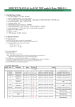
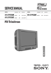
SERVICE MANUAL
MODEL
COMMANDER
DEST
FE-2 CHASSIS
MODEL
CHASSIS NO.
KV-29FX30B
KV-29FX30E
KV-29FX30K
COMMANDER
DEST
CHASSIS NO.
RM-887
FR
SCC-Q54J-A
RM-887
ESP
SCC-Q53K-A
RM-887
OIRT
SCC-Q51L-A
RM-889
1
SECTION 4 CIRCUIT ADJUSTMENTS
4-1. Electrical Adjustments
SERVICE
Offset-R
Offset-G
R-Drive
G-Drive
B-Drive
Peak-Freq
Luma-Delay
SC0
White-Peak
Subcont
Subright
Subcol
Subsharp
Cutoff Br.
Br OSD
Br TXT
Service adjustments to this model can be performed using the
suppliedemote Commander RM-887.
How to enter into the Service Mode
1.
2.
Turn on the main power switch and enter into the stand-by mode.
Press the following sequence of buttons on the Remote
Commander.
i+
5
+
(ON SCREEN
DISPLAY)
(DIGIT 5)
(VOLUME +)
(TV)
(0, 63)
(0, 63)
(0, 63)
(0, 63)
(0, 63)
(0, 3)
(0, 15)
(0, 3)
(0, 15)
(0, 15)
(0, 63)
(0, 63)
(0, 63)
(0, 63)
(0, 15)
(0, 15)
Adj
Adj
25
Adj
Adj
0
8
2
15
4
31
Adj
31
60
10
9
(0, 63)
(0, 63)
(0, 15)
(0, 15)
(0, 63)
(0, 63)
(0, 63)
(0, 63)
(0, 63)
(0, 63)
(0, 63)
(0, 63)
(0, 63)
(0, 63)
(0, 63)
(0, 63)
(0, 63)
(0, 63)
Adj
32
8
6
Adj
Adj
Adj
Adj
Adj
Adj
Adj
Adj
35
Adj
Adj
Adj
23
40
‘TT—’ will appear in the upper right corner of the screen.
Other status information will also be displayed.
GEOMETRY
3.
Press ‘MENU’ on the remote commander to obtain the following
menu on the screen.
V-Linearity
V-Scroll
Left-HBlk
Right-HBlk
V-Angle
V-Bow
H-Centre
H-Size
Pin-Amp
U-Corner-Pin
L-Corner-Pin
Pin Phase
V-Slope
V-Size
S-Correction
V-Centre
V-Zoom
Magenta
Geometry
Ser vice
Design
Status
Sound
IF adjust
Error Menu
FE-2 Stereo v1.30
Factor y data FFh FFh
MSP Device : MSP3411G
4.
5.
6.
Move to the corresponding adjustment item using the
up or down arrow buttons on the Remote Commander.
Press the right arrow button to enter into the required menu item.
Press the ‘Menu’ button on the Remote Commander to quit the
Service Mode when all adjustments have been completed.
IF ADJUST
AGC Adjust
Automute
Audio Gain
L Gating
Note :
•
Before performing any adjustments ensure that the correct model
has been selected in the ‘Model Setting’ menu.
•
After carrying out the service adjustments, to prevent the
customer
accessing the ‘Service Menu’ switch the TV set OFF and then
ON.
WORKING TIME
HOURS
MINUTES
OCP
OVP N/A
VSYNC
IKR
IIC
NVM
JUNGLE
TUNER
SOUNDP
8V
(0, 255)
(0, 255)
(0, 255)
(0, 255)
(0, 255)
(0, 255)
(0, 255)
(0, 255)
(0, 255)
(0, 255)
+0
1
0
0
Sub Brightness Adjustment
1.
2.
3.
ERROR MENU
E02
E03
E04
E05
E06
E07
E08
E09
E10
E11
(-16, +15)
0
0
0
0
0
0
0
0
0
0
Input a Monoscope pattern.
Press ‘TEST’ ‘TEST’ 13 on the Remote Commander.
Adjust the ‘Sub-Brightness’ data so that there is barely a
difference between the 0 IRE and 10 IRE signal levels.
Sub Contrast Adjustment
1.
2.
3.
2
11
20
Input a video signal that contains a small 100% white area on a
black background.
Connect an digital voltmeter to Pin 10 of J701 [C Board].
Adjust the Sub-Contrast [‘TT11’] to obtain a voltage of
105 +/- 5V (KV-29FX30) or 96 +/-5V (KV-25FX30).
Sub Colour Adjustment
1.
2.
3.
4.
Deflection System Adjustment
1.
2.
Receive a PAL colour bar signal.
Connect an oscilloscope to Pin 5 of CN003 [A Board].
Enter into the ‘Service’ service menu.
Adjust the ‘Sub Colour’ data so that the Cyan, Magenta and
Blue colour bars are of equal levels as indicated below.
Enter into the ‘Geometry’ service menu.
Select and adjust each item in order to obtain the optimum image.
GEOMETRY
V-Linearity
V-Scroll
Left-HBlk
Right-HBlk
V-Angle
V-Bow
H-Centre
H-Size
Pin-Amp
U-Corner-Pin
L-Corner-Pin
Pin Phase
V-Slope
V-Size
S-Correction
V-Centre
V-Zoom
Magenta
Same Level
B-Out Waveform
Tuner AGC Adjustment
(0, 63)
(0, 63)
(0, 15)
(0, 15)
(0, 63)
(0, 63)
(0, 63)
(0, 63)
(0, 63)
(0, 63)
(0, 63)
(0, 63)
(0, 63)
(0, 63)
(0, 63)
(0, 63)
(0, 63)
(0, 63)
Adj
32
8
6
Adj
Adj
Adj
Adj
Adj
Adj
Adj
Adj
35
Adj
Adj
Adj
23
40
Note:
There should be no need to adjust the AGC as this is preadjusted during manufacture of the FRONTEND. If the AGC
does need adjustment then follow steps 1. to 4. below.
V SIZE
1. Receive a signal of 62dBuV / 75 ohm terminated via the tuner
antenna socket.
2. Connect a voltmeter to pin1 of TU101 [print side of A Board]
or to the AGC pin of CN001 [mount side of A Board].
3. Confirm that the AGC voltage is 3.5volts +/- 0.3volts.
4. If adjustment is required, then re-adjust the AGC variable
resistor (located at the top rear of the FRONTEND) to obtain
a voltage of 3.5V +/- 0.3V.
V LIN
S CORRECTION
V CENTRE
H CENTRE
H SIZE
PIN AMP
PIN PHASE
[ Print side of A board ]
CORNER PIN
V ANGLE
21
4-2. TEST MODE 1:
27
28
31
33
35
36
38
41
43
44
45
46
48
49
51
52
54
55
56
57
61
62
63
64
65
66
67
68
69
71
72
73
74
78
79
87
89
91
92
93
94
95
99
Test Mode 1 is available by pressing the ‘TEST’ button once, OSD
‘T’ appears. The functions described below are available by selecting
the indicated keys. The ‘T’ is released automatically after each
command is executed.
KEY
T-MODE FUNCTION
volume +
volume maximum
volume -
Picture minimum
picture +
Picture maximum
picture -
Picture minimum
colour up
colour maximum
colour down
colour minimum
brightness - bright
brightness maximum
brightness - dark
brightness minimum
hue - purplish
hue - purplish
hue - greenish
hue - greenish
sharpness - sharp
sharpness maximum
sharpness - soft
shar pness minimum
balance left
balance full left
balance right
balance full right
treble up
treble maximum
treble down
treble minimum
bass up
bass maximum
bass down
bass minimum
4-3. TEST MODE 2:
Test Mode 2 is available by pressing the ‘TEST’ button twice, OSD
‘TT’ appears. The functions described below are available by
selecting the two numbers. To release the ‘Test mode 2’, press 00, 10,
20 ... twice or switch the TV set into Stand-by mode. In ‘TT Menu’
mode, it is possible to remove the Menu from the screen by pressing
the Speaker Off button once. Pressing the Speaker OFF button a
second time will cause the Menu to reappear. The function is kept
even when the menu is not displayed on screen !!.
00
01
02
03
04
05
06
07
08
11
12
13
14
15
16
19
21
22
23
24
25
26
'TT' mode off
Picture maximum
Picture minimum
Set speaker/headphone Volume
Set speaker/headphone Volume
Set speaker/headphone Volume
Set speaker/headphone Volume
Ageing mode
Shipping Condition
Sub picture adjustment
Sub colour adjustment
Sub Brightness adjustment
Text H Position adjustment
Rotation Coil Test
Picture level 50%
Factory Mode Enable/Disable
Destination ADEKR
Destination BL
Destination ADEKR
Destination U
Destination ADEKR
Destination BL
to
to
to
to
35%
50%
65%
80%
22
Destination ADEKR
Destination ADEKR
Auto Shutoff Enable/Disable
Rotation ON/OFF
CRT 4:3 <> 16:9 ; Display TV status
Velocity Modulation (VM) OFF/ON test
G2 adjustment
Re-initialise NVM
Select Dual A sound
Select Dual B sound
Select Mono sound
Select Stereo sound
Set NVM as non virgin
Set NVM as virgin
Vir tual Dolby on/off
Subwoofer / MPB (Bass enhancement) Enable
Dot structure C/M (chroma trap)ination ADEKR
Tuner selection (SONY/ALPS)
BBE enable/disable
BBE menu line enable/disable
Auto AGC Adjustment
AM from baseband enable/disable
Enable/Disable YC3 connector
Enable/Disable RGB priority
RGB auto-detect enable/disable
On timer enable/disable
Manual AGC Adjustment
Enable/Disable X26 countermeasure (N problem)
Enable/Disable ACI feature
Force PAL video
Un-force PAL (restore normal video condition)
Enable Zweiton D/K2 system (6.5/6.74)
Enable Zweiton D/K3 system (6.5/5.74)
Balance full left
Balance full right
Local keys test
Enable/Disable watchdog
Set 14:9 zoom mode
Set SMART zoom mode
Set 16:9 zoom mode
Set ZOOM mode
Set 4:3 zoom mode
Display Error and Working Time menu