1
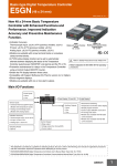
SERVICE MANUAL
MODEL
KV-25FX20A
KV-25FX20B
KV-25FX20D
KV-25FX20E
KV-25FX20K
KV-25FX20R
COMMANDER
DEST
CHASSIS NO.
RM-887
Italian
SCC-Q32B-A
RM-887
French
SCC-Q33B-A
RM-887
AEP
SCC-Q31B-A
RM-887
Spanish
SCC-Q34B-A
RM-887
OIRT
SCC-Q36C-A
RM-887
OIRT
SCC-Q36D-A
FE-1A CHASSIS
MODEL
COMMANDER
KV-29FX20A
KV-29FX20B
KV-29FX20D
KV-29FX201D
KV-29FX20E
KV-29FX201E
KV-29FX20K
KV-29FX20R
KV-29FX20U
DEST
CHASSIS NO.
RM-887
Italian
SCC-Q32A-A
RM-887
French
SCC-Q33A-A
RM-887
AEP
SCC-Q31A-A
RM-887
AEP
SCC-Q31E-A
RM-887
Spanish
SCC-Q34A-A
RM-887
ESP
SCC-Q34E-A
RM-887
OIRT
SCC-Q36B-A
RM-887
OIRT
SCC-Q36A-A
RM-887
UK
SCC-Q35A-A
TRINITRON ® COLOR TV
®
MICROFILM
1
ITEM MODEL
Italian
Television System
B/G/H
French
B/G/H, D/K, L, I
Stereo System
GERMAN Stereo
GERMAN/NICAM
Stereo
Channel Coverage
Color System
ITALIA VHF : A-H2 (C) UHF : 21-69 PAL
B/G/H VHF : E2-E12 UHF : E21-E69
CABLE TV (1) : S1-S41
CABLE TV (2) : S01-S05, M1-M10, U1-U10
PAL, SECAM
NTSC4.43, NTSC3.58
(VIDEO IN)
L VHF : F02-F10 UHF : F21-F60
CABLE : B-Q B/G/H VHF : E2-E12
UHF : E21-E69
CABLE TV (1) : S1-S41
CABLE TV (2) : S01-S05, M1-M10, U1-U10
ITALIA VHF : A-H2 (C) UHF : 21-69
I UHF : B21-B69
PAL, SECAM
NTSC4.43, NTSC3.58
(VIDEO IN)
PAL, SECAM
NTSC4.43, NTSC3.58
(VIDEO IN)
AEP
B/G/H
GERMAN Stereo
PAL B/G/H VHF : E2-E12 UHF : E21-E69
CABLE TV (1) : S1-S41
CABLE TV (2) : S01-S05, M1-M10, U1-U10
ITALIA VHF : A-H2 (C) UHF : 21-69
D/K VHF : R01-R12 UHF : R21-R69
Spanish
B/G/H, D/K
GERMAN/NICAM
Stereo
PAL B/G VHF : E2-E12 UHF : E21-E69
CABLE TV (1) : S1-S41
CABLE TV (2) : S01-S05, M1-M10, U1-U10
ITALIA VHF : A-H2 (C) UHF : 21-69
PAL, SECAM
NTSC4.43, NTSC3.58
(VIDEO IN)
B/G/H VHF : E2-E12 UHF : E21-E69
CABLE TV (1) : S1-S41
D/K VHF : R01-R12 UHF : R21-R69
PAL, SECAM
NTSC4.43, NTSC3.58
(VIDEO IN)
UHF : B21-B69
PAL
NTSC4.43, NTSC3.58
(VIDEO IN)
OIRT
B/G/H, D/K
KV-25FX20K/29FX20K
GERMAN/NICAM
Stereo
KV-25FX20R/29FX20R
GERMAN Stereo
UK
I
NICAM Stereo
MODEL
25FX20A
25FX20B
25FX20D
25FX20E
25FX20K
25FX20R
Power Consumption
100W
100W
100W
100W
100W
100W
MODEL
29FX20A
29FX20B
29FX20D
29FX20E
29FX20K
29FX20R
29FX20U
Power Consumption
120W
120W
120W
120W
120W
120W
150W
[PICTURE TUBE]
KV-25FX20
KV-29FX20
[FRONT]
FD Trinitron
Approx. 63cm (25 inches)
(Approx. 59cm picture measured
diagonally)
110 degree deflection
Video input - phono jack
Audio inputs - phono jacks
S Video input - 4 pin din
Headphone jacks : stereo minijack
Sound output
Subwoofer
Power requirements
Dimensions
KV-25FX20
KV-29FX20
Weight
KV-25FX20
KV-29FX20
Supplied accessories
FD Trinitron
Approx. 72cm (29 inches)
(Approx. 68cm picture measured
diagonally)
110 degree deflection
Input/Output Terminals
[REAR]
21-pin Euro connector (CENELEC standard).
Inputs for Audio and Video signals.
Inputs for RGB.
Outputs of TV Video and Audio signals.
-
2
-
21-pin Euro connector.
inputs for Audio and Video signals.
inputs for S Video.
outputs for Audio and Video signals (selectable).
-
Phono Jack
Outputs for Audio Signals
Other features
2 x 14W (Music Power)
30W (Music Power)
220 - 240V
Approx 655x509x476mm (w/h/d)
Approx 746x569x516mm (w/h/d)
Approx 37kg
Approx 47.5kg
RM-887 Remote Commander (1)
IEC designated R6 battery (2)
NICAM*, FASTEXT, TOPTEXT
*(KV-25FX20B/25FX20E/25FX20K/
KV-29FX20B/29FX20E/29FX20K/
KV-29FX20U only)
2
[RM-887]
Remote control system
Power requirements
Dimensions
Weight
Infrared control
3V dc
2 batteries IEC designation
R6 (size AA)
Approx 44x209x23mm (w/h/d)
Approx 89g (Not including battery)
Design and specifications are subject to change without notice.
Model Name
KV-25FX20A
KV-25FX20B
KV-25FX20D
KV-25FX20E
KV-25FX20K
KV-25FX20R
KV-29FX20A
KV-29FX20B
KV-29FX20D
KV-29FX20E
KV-29FX20K
KV-29FX20R
Pal Comb
OFF
OFF
OFF
OFF
OFF
OFF
OFF
PIP
OFF
OFF
OFF
OFF
OFF
OFF
OFF
RGB Priority
OFF
ON
ON
ON
OFF
OFF
OFF
Woofer Box
ON
ON
ON
ON
ON
ON
ON
Scart 1
ON
ON
ON
ON
ON
ON
ON
Scart 2
ON
ON
ON
ON
ON
ON
ON
Front in (3)
ON
ON
ON
ON
ON
ON
ON
Scart 4
OFF
OFF
OFF
OFF
OFF
OFF
OFF
Projector
OFF
OFF
OFF
OFF
OFF
OFF
OFF
AKB in 16:9 mode
ON
ON
ON
ON
ON
ON
ON
Norm B/G
ON
ON
ON
ON
ON
ON
OFF
Norm I
OFF
ON
OFF
OFF
OFF
OFF
ON
Norm D/K
OFF
ON
OFF
ON
ON
ON
OFF
Norm AUS
OFF
OFF
OFF
OFF
OFF
OFF
OFF
Norm L
OFF
ON
OFF
OFF
OFF
OFF
OFF
Norm SAT
OFF
OFF
OFF
OFF
OFF
OFF
OFF
Norm M
OFF
OFF
OFF
OFF
OFF
OFF
OFF
Teletext
ON
ON
ON
ON
ON
ON
ON
Nicam Stereo
OFF
ON
OFF
ON
ON
OFF
ON
Italian
French
German
Spanish
OIRT
OIRT
English
KV-29FX20U
Item
Language Preset
WARNING (KV-29FX20U only)
The flexible mains lead is supplied connected to a B.S. 1363 fused plug
having a fuse of 5 AMP capacity. Should the fuse need to be replaced,
use a 5 AMP FUSE approved by ASTA to BS 1362, ie one that carries the
ASA
T mark.
IF THE PLUG SUPPLIED WITH THIS APPLIANCE IS NOT SUITABLE
FOR THE OUTLET SOCKETS IN YOUR HOME, IT SHOULD BE CUT
OFF AND AN APPROPRIATE PLUG FITTED. THE PLUG SEVERED
FROM THE MAINS LEAD MUST BE DESTROYED AS A PLUG WITH
BARED WIRES IS DANGEROUS IF ENGAGED IN A LIVE OUTLET
SOCKET.
When an alternative type of plug is used it should be fitted with a 5 AMP
FUSE, otherwise the circuit should be protected by a 5 AMP FUSE at the
distribution board.
How to replace the fuse.
Open the fuse compartment with
a screwdriver blade and replace
the fuse.
FUSE
3
21 pin connector (
1/
,
2/
)
Pin No
1
2
4
Signal
1
21
20
19
Standard level : 0.5V rms
Output impedence : Less than 1kohm*
2
Audio output B
(right)
Standard level : 0.5V rms
Output impedence : More than 10kohm*
3
Audio output A
(left)
Standard level : 0.5V rms
Output impedence : Less than 1kohm*
4
Ground (audio)
5
Ground (blue)
6
Audio input A
(left)
Standard level : 0.5V rms
Output impedence : More than 10kohm*
7
Blue input
0.7 +/- 3dB, 75 ohms positive
8
Function select
(AV control)
High state (9.5-12V) : Part mode
Low state (0-2V) : TV mode
Input impedence : More than 10K ohms
Input capacitance : Less than 2nF
9
Ground (green)
10
Open
11
Green
12
Open
13
Ground (red)
14
16
15
_
15
_
_
Red input
0.7 +/- 3dB, 75 ohms, positive
(S signal Chroma
input)
0.3 +/- 3dB, 75 ohms, positive
High state (1-3V) Low state (0-0.4V)
Input impedence : 75 ohms
14
16
Blanking input
(Ys signal)
12
17
Ground (video
output)
10
18
Ground (video
input)
8
19
Video output
1V +/- 3dB, 75ohms, positive sync 0.3V
(-3+10dB)
Video input
1V +/- 3dB, 75ohms, positive sync 0.3V
(-3+10dB)
Video input
Y (S signal)
1V +/- 3dB, 75ohms, positive sync 0.3V
(-3+10dB)
13
11
9
7
_
6
5
Green signal : 0.7 +/- 3dB, 75 ohms,
positive
Ground (blanking)
18
17
Signal level
Audio output B
(right)
20
4
3
2
_
_
21
Common ground
(plug, shield)
1
Connected
Pin No.
4
Not Connected (open)
* at 20Hz - 20kHz
Signal Level
Signal
1
Ground
2
Ground
3
Y (S signal) input
1V
4
C (S signal) input
0.3V
3dB 75 ohm, positive Sync. 0.3V -3 + 10dB
3dB 75 ohm, positive Sync.
TABLE OF CONTENTS
Section
Title
Warning and Caution
FE-1A Self Diagnostic Software
Page
Section
Title
4-1.
4-2.
1. GENERAL
Overview of Remote
Control Buttons
Manually Tuning the TV
Fine Tuning Channels
Adjusting the Picture
Adjusting the Sound
Using the Sleep Timer
Viewing Teletext
Using Optional Equipment
Troubleshooting
Specifications
Rear Cover Removal
Chassis Assy Removal
Service Position
H Board Removal
S1 Board Removal
Picture Tube Removal
Removal and Replacement of
the Main - Bracket bottom plates
Electrical Adjustments
Test Mode 2
.....................7
5. DIAGRAMS
.....................7
.....................8
.....................8
.....................9
.....................9
.....................10
.....................10
.....................11
.....................11
5-1.
.....................12
.....................12
.....................13
.....................13
.....................13
.....................14
.....................15
5-4.
5-5.
5-2.
5-3.
2. DISASSEMBLY
2-1.
2-2.
2-3.
2-4.
2-5.
2-6.
2-7.
Page
4. CIRCUIT ADJUSTMENTS
.....................3
.....................6
Block Diagram (1)
Block Diagram (2)
Circuit Board Location
Schematic Diagrams and
Printed Wiring Boards
* S1 Board
* F Board
* K Board
* H Board
* A Board
* VM Board
* C Board
Semiconductors
IC Blocks
.....................20
.....................23
.....................25
.....................29
.....................32
.....................32
.....................33
.....................34
.....................36
.....................37
.....................41
.....................46
.....................50
.....................51
.....................53
6. EXPLODED VIEWS
6-1.
6-2.
Chassis
Picture Tube
7. ELECTRICAL PARTS LIST
.....................54
.....................56
.....................57
3. SET-UP ADJUSTMENTS
3-1.
3-2.
3-3.
3-4.
Beam Landing
Convergence
Focus
White Balance
.....................16
.....................17
.....................19
.....................19
CAUTION
ATTENTION
SHORT CIRCUIT THE ANODE OF THE PICTURE TUBE AND THE
ANODE CAP TO THE METAL CHASSIS, CRT SHIELD, OR THE
CARBON PAINTED ON THE CRT, AFTER REMOVAL OF THE
ANODE CAP
APRES AVOIR DECONNECTE LE CAP DE’LANODE,
COURT-CIRCUITER L’ANODE DU TUBE CATHODIQUE ET
CELUI DE L’ANODE DU CAP AU CHASSIS METALLIQUE
DE L’APPAREIL, OU AU COUCHE DE CARBONE PEINTE
SUR LE TUBE CATHODIQUE OU AU BLINDAGE DU TUBE
CATHODIQUE.
WARNING !!
ATTENTION !!
AN ISOLATING TRANSFORMER SHOULD BE USED DURING ANY
SERVICE WORK TO AVOID POSSIBLE SHOCK HAZARD DUE TO
LIVE CHASSIS. THE CHASSIS OF THIS RECEIVER IS DIRECTLY
CONNECTED TO THE POWER LINE.
AFIN D’EVITER TOUT RISQUE D’ELECTROCUTION PROVENANT
D’UN CHÁSSIS SOUS TENTION, UN TRANSFORMATEUR
D’ISOLEMENT DOIT ETRE UTILISÈ LORS DE TOUT DÈPANNAGE.
LE CHÁSSIS DE CE RÈCEPTEUR EST DIRECTMENT RACCORDÈ
Á L’ALIMENTATION SECTEUR.
SAFETY-RELATED COMPONENT WARNING !!
COMPONENTS IDENTIFIED BY SHADING AND MARKED
ON
THE SCHEMATIC DIAGRAMS, EXPLODED VIEWS AND IN THE
PARTS LIST ARE CRITICAL FOR SAFE OPERATION. REPLACE
THESE COMPONENTS WITH SONY PARTS WHOSE PART NUMBERS
APPEAR AS SHOWN IN THIS MANUAL OR IN SUPPLEMENTS
PUBLISHED BY SONY.
ATTENTION AUX COMPOSANTS RELATIFS Á LA
SÈCURITÈ !!
LES COMPOSANTS IDENTIFIÈS PAR UNE TRAME ET PAR UNE
MARQUE
SUR LES SCHÈMAS DE PRINCIPE, LES VUES
EXPLOSÈES ET LES LISTES DE PIECES SONT D’UNE IMPORTANCE
CRITIQUE POUR LA SÈCURITÈ DU FONCTIONNEMENT, NE LES
REMPLACER QUE PAR DES COMPSANTS SONY DONT LE NUMÈRO
DE PIÈCE EST INDIQUÈ DANS LE PRÈSENT MANUEL OU DANS
DES SUPPLÈMENTS PUBLIÈS PAR SONY.
5
FE-1A SELF DIAGNOSTIC SOFTWARE
The identification of errors within the FE-1A chassis is triggered in one of two ways :- 1: Busy or 2: Device failure to respond to IIC. In the event
of one of these situations arising the software will first try to release the bus if busy (Failure to do so will report with continuous flashing LED) and
then communicate with each device in turn to establish if a device is faulty. If a device is found to be faulty the relevant device number will be displayed through the LED (Series of flashes which must be counted) See Table 1., non fatal errors are reported using this method.
Each time the software detects an error it is stored within the NVM. See Table 2.
Table 1
How to enter into Table 2
LED
ERROR
COUNT
ERROR
No error
00
Not allowed (may be confused with Sircs response
flash!)
01
Protection circuit trip < ANY TIME >
02
Reserved
03
No vertical sync
04
AKB
05
IIC bus clock and/or data lines low at Power ON
06
NVM no IIC bus acknowledge at Power ON
07
Jungle controller no IIC acknowledge at Power ON
08
Tuner no acknowledge at Power ON
09
Sound processor no acknowledge at Power ON
10
1.
2.
Turn on the main power switch of the TV set and enter into the
‘Standby Mode’.
Press the following sequence of buttons on the Remote
Commander.
i+
5
(ON SCREEN
DISPLAY)
(DIGIT 5)
3.
The following table will be displayed indicating the error
count.
Error
2
3
4
5
6
7
8
9
10
StBy LED
ON
OFF
(TV)
Table 2
Flash Timing Example : e.g. error number 3
ON
(VOLUME -)
ON
Times
-
OFF
Note: To clear the error count data press ‘80’ on the Remote
commander.
6