1
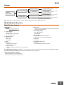
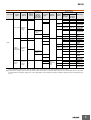
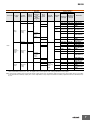
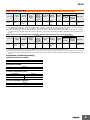
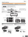
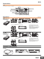
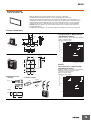
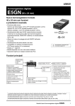
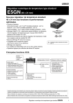
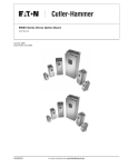
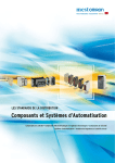
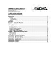
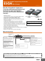
Basic-type Digital Temperature Controller
E5GN
(48 x 24 mm)
CSM_E5GN_DS_E_5_1
New 48 x 24-mm Basic Temperature
Controller with Enhanced Functions and
Performance. Improved Indication
Accuracy and Preventive Maintenance
Function.
• Indication Accuracy
E5GN--@-C
E5GN
Thermocouple input: ±0.3% of PV (previous models: ±0.5%)
Models with Screw Terminal Models with Screwless Clamp
Terminal Blocks
Blocks
Pt input: ±0.2% of PV (previous models: ±0.5%)
48 × 24 mm
48 × 24 mm
Analog input: ±0.2% FS (previous models: ±0.5%)
• Models are available with screw terminal blocks or screwless
clamp terminal blocks.
• A PV/SV-status display function can be set to automatically
Refer to Safety Precautions for E5@N/E5@N-H.
alternate between displaying the status of the Temperature
Controller (auto/manual, RUN/STOP, and alarms) and the PV or SV.
Refer to Operation for E5@N/E5@N-H for operating
• Preventive maintenance for relays in the Temperature Controller
procedures.
using a Control Output ON/OFF Counter.
• Switch the PV display between three colors.
• Compatible with Support Software (CX-Thermo version 4.2 or higher).
• Eleven-segment displays.
• Models are available with one or two alarm outputs.
Main I/O Functions
Event Inputs
• None
• Two
E5GN
Dual Display: PV and SV
Sensor Inputs
• Universal thermocouple/Pt inputs
(Models with temperature inputs)
• Analog current/voltage inputs
(Models with analog inputs)
Indication Accuracy
• Thermocouple input: ±0.3% of PV
• Pt input: ±0.2% of PV
• Analog input: ±0.2% FS
Sampling Period
• 250 ms
Auxiliary Outputs
• None
• One
• Two
Control Output 1
• Relay output
• Voltage output (for driving SSR)
• Current output
4-digit Display
• Auto/manual switching
• Temperature Controller status display
• Simple program function
• Control output ON/OFF count alarm
• PV change rate alarm
• Models also available with RS-232C
communications
• Models also available with RS-485
communications
This datasheet is provided as a guideline for selecting products. Be sure to refer to the following user manuals for application precautions
and other information required for operation before attempting to use the product.
E5CN/E5AN/E5EN/E5GN Digital Temperature Controllers User's Manual Basic Type (Cat. No. H156)
E5CN/E5AN/E5EN/E5GN Digital Temperature Controllers Communications Manual Basic Type (Cat. No. H158)
1
E5GN
Lineup
Temperature input
1 control output
0, 1, or 2 auxiliary
outputs
Analog input
1 control output
0, 1, or 2 auxiliary
outputs
Temperature input
1 control output
0, 1, or 2 auxiliary
outputs
Analog input
1 control output
0, 1, or 2 auxiliary
outputs
Screw terminal block
E5GN
Basic Type
Screwless clamp
terminal block
Note: Models with one control output and one or two auxiliary outputs can be used for heating/cooling control.
Model Number Structure
Model Number Legend
Controllers
E5GN-@@@@@-@-@-@
1 2 3 4 5
6
7
8
1. Control Output 1
R: Relay output
Q: Voltage output (for driving SSR)
C: Linear current output
2. Auxiliary Outputs
Blank: None
1: One output
2: Two outputs
4. Input Type
T: Universal thermocouple/platinum resistance thermometer input
L: Analog current/voltage input
5. Power Supply Voltage
Blank: 100 to 240 VAC
D: 24 VAC/VDC
6. Terminal Type
Blank: Models with screw terminal block
C: Models with screwless clamp terminal block
7. Case Color
Blank: Black
3. Option
8. Communications Protocol
Blank: None
Blank: None
01: RS-232C communications
FLK: CompoWay/F serial communications
03: RS-485 communications
B: Two event inputs
H: Heater burnout/Heater short/Heater overcurrent detection
(CT1)
Note: Models cannot be made for all combinations of options that are possible in the model number legend. Confirm model availability in Ordering
Information before ordering.
* Auxiliary outputs are relay outputs that can be used for output alarms or processing results.
Supply Voltage Suffixes for Ordering
For 100 to 240 VAC, add a "AC100240" suffix.
For 24 VAC/VDC models, add a "ACDC24" suffix.
2
E5GN
Ordering Information
Controllers with Screw Terminal Blocks
Models with Temperature Inputs
Models with One Control Output and a 100 to 240-VAC Power Supply (Add AC100240 to the Model number.)
Case color
Control
output
No. of
auxiliary
outputs
Control
mode *1
Standard
Detection of
heater
burnout,
SSR failure,
and heater
overcurrent
---
Previous model
No. of event
inputs
Transfer
output *2
---
Communications
Relay output
Standard or
heating/
cooling
---
---
2
Standard
---
---
---
---
E5GN-R1BT
---
---
E5GNR101T-FLK
RS-485
E5GN
E5GN
-R03TC-FLK -R03P-FLK
E5GNR103T-FLK
---
---
E5GN-R2T
---
---
E5GN-R2HT
---
---
E5GN-R2BT
RS-485
---
---
E5GNR203T-FLK
E5GN-QTC
E5GN-QP
---
E5GN-Q1TC E5GN-Q1P
E5GN-Q1T
---
---
E5GN-Q1BT
RS-232C
---
---
E5GNQ101T-FLK
RS-485
E5GN
E5GN
-Q03TC-FLK -Q03P-FLK
E5GNQ103T-FLK
---
---
E5GN-Q2T
---
---
---
E5GN-Q2HT
---
---
E5GN-Q2BT
RS-485
---
---
E5GNQ203T-FLK
---
---
E5GN-C1T
---
---
E5GN-C1BT
RS-232C
---
---
E5GNC101T-FLK
RS-485
---
---
E5GNC103T-FLK
2
Black
1
Voltage
output (for
driving SSR)
Standard or
heating/
cooling
---
---
2
---
Detection for
single-phase
heaters
2
---
-----
Current
output
Standard or
heating/
cooling
2
1
-----
--Transfer
output using
control
output
E5GN-RT
RS-232C
---
---
E5GN-RP
E5GN-R1T
2
---
E5GN-RTC
New model
E5GN-R1TC E5GN-R1P
---
Detection for
single-phase
heaters
Resistance
thermometer input
---
2
1
Thermocouple input
E5GN-QT
*1. If heating/cooling control mode is used, an auxiliary output is used as a control output for the cooling side. The number of auxiliary outputs that
can be used will decrease by one. Also, the signal for the control output for the cooling side will be a relay output.
*2. A current control output can be used as the transfer output. In that case, an auxiliary output is used as the control output. (This is not possible
for models without an auxiliary output.) The control output will be a relay output. The number of auxiliary outputs that can be used will decrease
by one.
3
E5GN
Models with One Control Output and a 24-VAC/VDC Power Supply (Add ACDC24 to the Model number.)
Case color
Control
output
No. of
auxiliary
outputs
Control
mode *1
Standard
Detection of
heater
burnout,
SSR failure,
and heater
overcurrent
---
Previous model
No. of event
inputs
Transfer
output *2
Communications
Thermocouple input
E5GN-RTC
---
---
2
1
Relay output
Standard or
heating/
cooling
---
2
Standard
---
---
E5GN-R1BTD
---
E5GN
-R101TD-FLK
RS-485
E5GN
E5GN
-R03TC-FLK -R03P-FLK
E5GN
-R103TD-FLK
---
---
E5GN-R2TD
---
---
E5GN-R2HTD
---
---
E5GN-R2BTD
---
---
E5GN
-R203TD-FLK
E5GN-QTC
E5GN-QP
---
---
RS-485
---
E5GN-Q1TD
---
---
E5GNQ1BTD
RS-232C
---
---
E5GNQ101TD-FLK
RS-485
E5GN
E5GN
-Q03TC-FLK -Q03P-FLK
E5GN
-Q103TD-FLK
---
---
E5GN-Q2TD
---
---
E5GNQ2HTD
---
---
E5GNQ2BTD
---
---
E5GN
-Q203TD-FLK
--Black
Voltage
output (for
driving SSR)
Standard or
heating/
cooling
---
---
2
---
Detection for
single-phase
heaters
--2
-----
RS-485
--Current
output
Standard or
heating/
cooling
2
1
-----
---
---
E5GN-C1TD
---
---
E5GN-C1BTD
RS-232C
---
---
E5GN
-C101TD-FLK
RS-485
---
---
E5GN
-C103TD-FLK
--Transfer
output using
control
output
E5GN-QTD
E5GN-Q1TC E5GN-Q1P
2
1
E5GN-RTD
E5GN-R1TD
---
2
---
New model
RS-232C
---
Detection for
single-phase
heaters
E5GN-RP
E5GN-R1TC E5GN-R1P
---
---
Resistance
thermometer input
*1. If heating/cooling control mode is used, an auxiliary output is used as a control output for the cooling side. The number of auxiliary outputs that
can be used will decrease by one. Also, the signal for the control output for the cooling side will be a relay output.
*2. A current control output can be used as the transfer output. In that case, an auxiliary output is used as the control output. (This is not possible
for models without an auxiliary output.) The control output will be a relay output. The number of auxiliary outputs that can be used will decrease
by one.
4
E5GN
Models with Analog Inputs
Models with One Control Output and a 100 to 240-VAC Power Supply (Add AC100240 to the Model number.)
Case color
Control
output
No. of
auxiliary
outputs
Control
mode *1
Detection of
heater
burnout,
SSR failure,
and heater
overcurrent
Previous model
No. of event
inputs
Transfer
output *2
CommuniThermocoucations
ple input
Relay output
Black
Voltage
output (for
driving SSR)
--Standard or
heating/
cooling
1
---
Resistance
thermometer input
---
---
E5GNR103L-FLK
---
---
E5GNQ103L-FLK
---
---
E5GN-C1L
RS-485
--Transfer
output using
control
output
Current
output
---
New model
Note: Models with analog inputs do not display the temperature unit.
*1. If heating/cooling control mode is used, an auxiliary output is used as a control output for the cooling side. The number of auxiliary outputs that
can be used will decrease by one. Also, the signal for the control output for the cooling side will be a relay output.
*2. A current control output can be used as the transfer output. In that case, an auxiliary output is used as the control output. (This is not possible
for models without an auxiliary output.) The control output will be a relay output. The number of auxiliary outputs that can be used will decrease
by one.
Models with One Control Output and a 24-VAC/VDC Power Supply (Add ACDC24 to the Model number.)
Case color
Control
output
No. of
auxiliary
outputs
Control
mode *1
Detection of
heater
burnout,
SSR failure,
and heater
overcurrent
Previous model
No. of event
inputs
Transfer
output *2
CommuniThermocoucations
ple input
Relay output
Black
Voltage
output (for
driving SSR)
Current
output
Standard or
heating/
cooling
--1
---
Resistance
thermometer input
---
---
E5GNR103LD-FLK
---
---
E5GN
-Q103LD-FLK
---
---
E5GN-C1LD
RS-485
--Transfer
output using
control
output
---
New model
*1. If heating/cooling control mode is used, an auxiliary output is used as a control output for the cooling side. The number of auxiliary outputs that
can be used will decrease by one. Also, the signal for the control output for the cooling side will be a relay output.
*2. A current control output can be used as the transfer output. In that case, an auxiliary output is used as the control output. (This is not possible
for models without an auxiliary output.) The control output will be a relay output. The number of auxiliary outputs that can be used will decrease
by one.
5
E5GN
Controllers with Screwless Clamp Terminal Blocks
Models with Temperature Inputs
Models with One Control Output and a 100 to 240-VAC Power Supply (Add AC100240 to the Model number.)
Case color
Control
output
No. of
auxiliary
outputs
Control
mode *1
Standard
Detection
of heater
No. of event
burnout,
inputs
SSR failure,
and heater
overcurrent
---
Previous model
Transfer
output *2
---
Communic
ations
---
2
1
Relay output Standard or
heating/
cooling
---
---
2
Standard
---
1
E5GN-R1BT-C
E5GN
-R101T-C-FLK
RS-485
E5GN
E5GN
-R03TC-FLK -R03P-FLK
E5GN
-R103T-C-FLK
---
---
E5GN-R2T-C
---
---
E5GN-R2HT-C
---
---
E5GN-R2BT-C
---
---
E5GN
-R203T-C-FLK
E5GN-QTC
E5GN-QP
E5GN-QT-C
---
Voltage
Standard or
output (for
driving SSR) heating/
cooling
---
2
--Current
output
Standard or
heating/
cooling
2
1
---
---
RS-485
E5GN
E5GN
-Q03TC-FLK -Q03P-FLK
E5GN
-Q103T-C-FLK
---
---
E5GN-Q2T-C
---
---
---
E5GN-Q2HT-C
---
---
E5GN-Q2BT-C
RS-485
---
---
E5GN
-Q203T-C-FLK
---
---
E5GN-C1T-C
---
---
E5GN-C1BT-C
--Transfer
output using
control
output
E5GN-Q1BT-C
E5GN
-Q101T-C-FLK
---
2
---
E5GN-Q1T-C
---
RS-232C
---
Detection for
singlephase
heaters
---
E5GN-Q1TC E5GN-Q1P
---
---
E5GN-R1T-C
---
2
Black
E5GN-RT-C
---
RS-485
---
E5GN-RP
E5GN-R1TC E5GN-R1P
RS-232C
---
---
E5GN-RTC
New model
---
2
---
Resistance
thermometer input
---
---
Detection for
singlephase
heaters
Thermocouple input
RS-232C
---
---
E5GN
-C101T-C-FLK
RS-485
---
---
E5GN
-C103T-C-FLK
*1. If heating/cooling control mode is used, an auxiliary output is used as a control output for the cooling side. The number of auxiliary outputs that
can be used will decrease by one. Also, the signal for the control output for the cooling side will be a relay output.
*2. A current control output can be used as the transfer output. In that case, an auxiliary output is used as the control output. (This is not possible
for models without an auxiliary output.) The control output will be a relay output. The number of auxiliary outputs that can be used will decrease
by one.
6
E5GN
Models with One Control Output and a 24-VAC/VDC Power Supply (Add ACDC24 to the Model number.)
Case color
Control
output
No. of
auxiliary
outputs
Control
mode *1
Standard
Detection
of heater
burnout,
SSR
failure, and
heater
overcurren
t
---
Previous model
No. of
event
inputs
Transfer
output *2
---
Communic
ations
---
2
1
Relay
output
Standard or
heating/
cooling
2
---
---
Voltage
output (for
driving
SSR)
Standard or
heating/
cooling
---
---
2
-----
Current
output
Standard or
heating/
cooling
2
---
E5GN-R2TD-C
---
---
E5GN-R2HTD-C
---
---
E5GN-R2BTD-C
RS-485
---
---
E5GN
-R203TD-C-FLK
E5GN-QTC
E5GN-QP
---
E5GN-Q1TC E5GN-Q1P
---
---
E5GN-Q1BTD-C
RS-232C
---
---
E5GN
-Q101TD-C-FLK
RS-485
E5GN
E5GN
-Q03TC-FLK -Q03P-FLK
E5GN
-Q103TD-C-FLK
---
---
E5GN-Q2TD-C
---
---
---
E5GN-Q2HTD-C
---
---
E5GN-Q2BTD-C
RS-485
---
---
E5GN
-Q203TD-C-FLK
---
---
E5GN-C1TD-C
---
---
E5GN-C1BTD-C
1
-----
RS-232C
---
---
E5GN
-C101TD-C-FLK
RS-485
---
---
E5GN
-C103TD-C-FLK
--Transfer
output using
control
output
---
---
2
---
E5GN-R1BTD-C
E5GN
-R101TD-C-FLK
E5GN
-R103TD-C-FLK
---
Detection
for singlephase
heaters
---
RS-485
2
1
E5GN-RTD-C
E5GN-R1TD-C
E5GN
E5GN
-R03TC-FLK -R03P-FLK
---
---
Black
E5GN-RP
---
2
Standard
E5GN-RTC
E5GN-R1TC E5GN-R1P
New model
RS-232C
---
Detection
for singlephase
heaters
---
Resistance
thermometer input
---
---
---
Thermocouple input
E5GN-QTD-C
E5GN-Q1TD-C
*1. If heating/cooling control mode is used, an auxiliary output is used as a control output for the cooling side. The number of auxiliary outputs that
can be used will decrease by one. Also, the signal for the control output for the cooling side will be a relay output.
*2. A current control output can be used as the transfer output. In that case, an auxiliary output is used as the control output. (This is not possible
for models without an auxiliary output.) The control output will be a relay output. The number of auxiliary outputs that can be used will decrease
by one.
7
E5GN
Models with Analog Inputs
Models with One Control Output and a 100 to 240-VAC Power Supply (Add AC100240 to the Model number.)
Case color
Control
output
Current
output
Black
No. of
auxiliary
outputs
Control
mode *1
Standard or
heating/
cooling
1
Detection of
heater
burnout,
SSR failure,
and heater
overcurrent
Previous model
No. of event
inputs
---
---
Transfer
output *2
Transfer
output using
control
output
Communi
cations
---
Thermocouple input
Resistance
thermometer input
---
---
New model
E5GN-C1L-C
Note: Models with analog inputs do not display the temperature unit.
*1. If heating/cooling control mode is used, an auxiliary output is used as a control output for the cooling side. The number of auxiliary outputs that
can be used will decrease by one. Also, the signal for the control output for the cooling side will be a relay output.
*2. A current control output can be used as the transfer output. In that case, an auxiliary output is used as the control output. (This is not possible
for models without an auxiliary output.) The control output will be a relay output. The number of auxiliary outputs that can be used will decrease
by one.
Models with One Control Output and a 24-VAC/VDC Power Supply (Add ACDC24 to the Model number.)
Case color
Black
Control
output
Current
output
No. of
auxiliary
outputs
Control
mode *1
Standard or
heating/
cooling
1
Detection of
heater
burnout,
SSR failure,
and heater
overcurrent
Previous model
No. of event
inputs
---
---
Transfer
output *2
Transfer
output using
control
output
Communi
cations
---
Thermocouple input
Resistance
thermometer input
---
---
New model
E5GN-C1LDC
*1. If heating/cooling control mode is used, an auxiliary output is used as a control output for the cooling side. The number of auxiliary outputs that
can be used will decrease by one. Also, the signal for the control output for the cooling side will be a relay output.
*2. A current control output can be used as the transfer output. In that case, an auxiliary output is used as the control output. (This is not possible
for models without an auxiliary output.) The control output will be a relay output. The number of auxiliary outputs that can be used will decrease
by one.
Accessories (Order Separately)
USB-Serial Conversion Cable
Model
E58-CIFQ1
Waterproof Packing
Model
Y92S-32
Current Transformers (CTs)
Hole diameter
Model
5.8 dia.
E54-CT1
12.0 dia.
E54-CT3
CX-Thermo Support Software
Model
EST2-2C-MV4
Note: The E5GN is supported by CX-Thermo version 4.2 and higher.
8
E5GN
Specifications
Ratings
Power supply voltage
No D in model number: 100 to 240 VAC, 50/60 Hz
D in model number: 24 VAC, 50/60 Hz; 24 VDC
Operating voltage range
85% to 110% of rated supply voltage
Power
consumption
E5GN
Screw terminal
block
100 to 240 VAC: 5.5 VA (max.)
24 VAC/VDC: 3 VA/2 W (max.)
E5GN-@-C
Screwless clamp
terminal block
100 to 240 VAC: 5.5 VA (max.)
24 VAC/VDC: 3 VA/2 W (max.)
Sensor input
Models with temperature inputs
Thermocouple: K, J, T, E, L, U, N, R, S, B, W, or PL II
Platinum resistance thermometer: Pt100 or JPt100
Infrared temperature sensor: 10 to 70°C, 60 to 120°C, 115 to 165°C, or 140 to 260°C
Voltage input: 0 to 50 mV
Models with analog inputs
Current input: 4 to 20 mA or 0 to 20 mA
Voltage input: 1 to 5 V, 0 to 5 V, or 0 to 10 V
Input impedance
Control method
Control
outputs
Auxiliary
outputs
Event
inputs
Current input: 150 Ω max., Voltage input: 1 MΩ min. (Use a 1:1 connection when connecting the ES2-HB.)
ON/OFF control or 2-PID control (with auto-tuning)
Relay output
SPST-NO, 250 VAC, 2 A (resistive load), electrical life: 100,000 operations, minimum applicable load: 5 V,
10 mA
Voltage output
(for driving SSR)
Output voltage: 12 VDC ±15% (PNP), max. load current: 21 mA, with short-circuit protection circuit
Current output
4 to 20 mA DC/0 to 20 mA DC, load: 500 Ω max., resolution: approx. 10,000
Number of outputs 1 or 2 max. (Depends on the model.)
Output
specifications
Relay output: SPST-NO, 250 VAC, 2 A (resistive load), electrical life: 100,000 operations, minimum
applicable load: 5 V, 10 mA
Number of inputs
2
External contact
input
specifications
Contact input: ON: 1 kΩ max., OFF: 100 kΩ min.
Non-contact input: ON: Residual voltage: 1.5 V max., OFF: Leakage current: 0.1 mA max.
Current flow: Approx. 7 mA per contact
Setting method
Digital setting using front panel keys
Indication method
11-segment digital display and individual indicators (7-segment display also possible)
Character height: PV: 7.5 mm, SV: 3.6 mm
Multi SP
Up to four set points (SP0 to SP3) can be saved and selected using event inputs, key operations, or serial
communications.
Bank switching
Not supported
Other functions
Manual output, heating/cooling control, loop burnout alarm, SP ramp, other alarm functions, heater burnout
detection, 40% AT, 100% AT, MV limiter, input digital filter, self-tuning, temperature input shift, run/stop,
protection functions, control output ON/OFF counter, extraction of square root, MV change rate limit, logic
operations, PV/SV status display, simple program, automatic cooling coefficient adjustment
Ambient operating temperature −10 to 55°C (with no condensation or icing), for 3-year warranty: −10 to 50°C
Ambient operating humidity
25% to 85%
Storage temperature
−25 to 65°C (with no condensation or icing)
9
E5GN
Input Ranges
Thermocouple/Platinum Resistance Thermometer (Universal Inputs)
Input
Type
Platinum resistance
thermometer
Name
Pt100
Infrared temperature
sensor
Thermocouple
JPt100
K
J
T
E
L
U
N
R
S
B
W
PL
II
10 to
70°C
60 to
120
°C
115
to
165
°C
140
to
260
°C
Analog
input
0 to
50 mV
2300
2300
1800
1800
1700 1700
1700
1600
1500
Temperature range (°C)
1400
1300
1300
1300
1300
Usable
in the
following
ranges
by
scaling:
−1999 to
9999 or
−199.9
to 999.9
1200
1100
1000
900
850
850
850
800
700
600
600
500.0
500
500.0
500.0
400.0
400
400
400.0
400
400.0
260
300
200
100.0
100
0.0
−100.0
Setting
number
165
90
100
0
−200.0
100.0
120
0.0
−20.0 −100 −20.0
−200 −199.9
0
1
−199.9
2
−200
3
4
5
−200 −199.9 −200
6
7
0
0
16
17
0
0
0
0
0
0
24
25
19
20
21
22
−100
8
9
10
11
−200 −199.9 −200
12
13
14
15
18
23
Shaded settings are the default settings.
The applicable standards for the input types are as follows:
K, J, T, E, N, R, S, B: JIS C 1602-1995, IEC 584-1
L: Fe-CuNi, DIN 43710-1985
U: Cu-CuNi, DIN 43710-1985
W: W5Re/W26Re, ASTM E988-1990
JPt100: JIS C 1604-1989, JIS C 1606-1989
Pt100: JIS C 1604-1997, IEC 751
PL II: According to Platinel II electromotive force charts from BASF (previously Engelhard)
Models with Analog Inputs
Input Type
Current
Voltage
Input specification
4 to 20 mA
0 to 20 mA
Setting range
Usable in the following ranges by scaling:
−1999 to 9999, −199.9 to 999.9, −19.99 to 99.99 or −1.999 to 9.999
Setting number
0
1
1 to 5 V
2
0 to 5 V
3
0 to 10 V
4
Shaded settings are the default settings.
10
E5GN
Alarm Outputs
Each alarm can be independently set to one of the following 13 alarm types. The default is 2: Upper limit.
Auxiliary outputs are allocated for alarms. ON delays and OFF delays (0 to 999 s) can also be specified.
Note: For models with heater burnout, SSR failure, and heater overcurrent detection, alarm 1 will be an OR output of the alarm selected from the
following alarm types and the alarms for heater burnout, SSR failure, and heater overcurrent. To output only a heater burnout alarm, SSR
failure alarm, and heater overcurrent alarm for alarm 1, set the alarm type to 0 (i.e., no alarm function).
Alarm output operation
Set value
0
Alarm type
Alarm function OFF
Output OFF
1 *1
Upper- and lower-limit
ON
OFF
2
Upper-limit
ON
OFF
3
4 *1
Upper- and lower-limit range
5 *1
Upper- and lower-limit with
standby sequence
11
X
ON
OFF
ON
OFF
SP
L H
SP
SP
*4
A standby sequence is added to the upper- and
lower-limit alarm (1). *6
X
ON
OFF
ON
OFF
Absolute-value lower-limit with
standby sequence
ON
OFF
ON
OFF
SP
X
ON
OFF
SP
X
ON
OFF
0
X
ON
OFF
0
X
ON
OFF
0
X
ON
OFF
0
LBA (alarm 1 type only)
---
PV change rate alarm
---
*1. With set values 1, 4 and 5, the upper and lower limit values can
be set independently for each alarm type, and are expressed as
“L” and “H.”
*2. Set value: 1, Upper- and lower-limit alarm
Case 3 (Always ON)
H < 0, L < 0
H SP
H < 0, L > 0
⏐H⏐ < ⏐L⏐
H
SP L H
H > 0, L < 0
⏐H⏐ > ⏐L⏐
H
SP
L
H < 0, L > 0
⏐H⏐ ≥ ⏐L⏐
L SP
SP H
L
H > 0, L < 0
⏐H⏐ ≤ ⏐L⏐
*3. Set value: 4, Upper- and lower-limit range
Case 1
Set the downward deviation in the set point by setting
the alarm value (X).
Set the deviation in the set point by setting the alarm
upper limit (H) and alarm lower limit (L).
13
L
X
SP
L H
ON
OFF
Absolute-value upper-limit with
standby sequence
Case 2
Set the upward deviation in the set point by setting
the alarm value (X).
SP
*3
12
Case 1
X
X
ON
OFF
ON
OFF
Absolute-value lower-limit
10
Set the deviation in the set point by setting the alarm
upper limit (H) and alarm lower limit (L).
*2
*5
Absolute-value upper-limit
9
No alarm
SP
ON
OFF
Lower-limit with standby sequence
8
SP
ON
OFF
Upper-limit with standby sequence
7
L H
ON
OFF
Lower-limit
6
Description of function
When alarm value When alarm value
X is positive
X is negative
X
A standby sequence is added to the upper-limit alarm
(2). *6
SP
X
A standby sequence is added to the lower-limit alarm
(3). *6
SP
X
0
The alarm will turn ON if the process value is larger
than the alarm value (X) regardless of the set point.
0
The alarm will turn ON if the process value is smaller
than the alarm value (X) regardless of the set point.
0
A standby sequence is added to the absolute-value
upper-limit alarm (8). *6
0
A standby sequence is added to the absolute-value
lower-limit alarm (9). *6
X
X
X
*7
*8
*5. Set value: 5, Upper- and lower-limit with standby sequence
Always OFF when the upper-limit and lower-limit hysteresis
overlaps.
*6. Refer to the E5CN/E5AN/E5EN/E5GN Digital Temperature
Controllers User's Manual Basic Type (Cat. No. H156) for
information on the operation of the standby sequence.
*7. Refer to the E5CN/E5AN/E5EN/E5GN Digital Temperature
Controllers User's Manual Basic Type (Cat. No. H156) for
information on the loop burnout alarm (LBA).
*8. Refer to the E5CN/E5AN/E5EN/E5GN Digital Temperature
Controllers User's Manual Basic Type (Cat. No. H156) for
information on the PV change rate alarm.
Case 3 (Always OFF)
Case 2
H < 0, L < 0
L
H SP
H < 0, L > 0
⏐H⏐ < ⏐L⏐
SP L
H
H
H > 0, L < 0
⏐H⏐ > ⏐L⏐
H
SP
L
L SP
SP H L
H < 0, L > 0
⏐H⏐ ≥ ⏐L⏐
H > 0, L < 0
⏐H⏐ ≤ ⏐L⏐
*4. Set value: 5, Upper- and lower-limit with standby sequence
For Upper- and Lower-Limit Alarm Described Above
• Case 1 and 2
Always OFF when the upper-limit and lower-limit hysteresis
overlaps.
• Case 3: Always OFF
11
E5GN
Characteristics
Indication accuracy
Influence of temperature *2
Influence of voltage *2
Thermocouple: *1
(±0.3% of indicated value or ±1°C, whichever is greater) ±1 digit max.
Platinum resistance thermometer input:
(±0.2% of indicated value or ±0.8°C, whichever is greater) ±1 digit max.
Analog input:
±0.2% FS ±1 digit max.
CT input:
±5% FS ±1 digit max.
Thermocouple input (R, S, B, W, PL II):
(±1% of PV or ±10°C, whichever is greater) ±1 digit max.
Other thermocouple input: *3
(±1% of PV or ±4°C, whichever is greater) ±1 digit max.
Platinum resistance thermometer input:
(±1% of PV or ±2°C, whichever is greater) ±1 digit max.
Analog input:
(±1%FS) ±1 digit max.
Input sampling period
250 ms
Hysteresis
Models with thermocouple/platinum resistance thermometer input (universal input): 0.1 to 999.9 EU (in units of 0.1 EU) *4
Models with analog input: 0.01 to 99.99% FS (in units of 0.01% FS)
Proportional band (P)
Models with thermocouple/platinum resistance thermometer input (universal input): 0.1 to 999.9 EU (in units of 0.1 EU) *4
Models with analog input: 0.1 to 999.9% FS (in units of 0.1% FS)
Integral time (I)
0 to 3999 s (in units of 1 s)
Derivative time (D)
0 to 3999 s (in units of 1 s) *5
Control period
0.5, 1 to 99 s (in units of 1 s)
Manual reset value
0.0 to 100.0% (in units of 0.1%)
Alarm setting range
−1999 to 9999 (decimal point position depends on input type)
Affect of signal source
resistance
Thermocouple: 0.1°C/Ω max. (100 Ω max.)
Platinum resistance thermometer: 0.1°C/Ω max. (10 Ω max.)
Insulation resistance
20 MΩ min. (at 500 VDC)
Dielectric strength
2,300 VAC, 50 or 60 Hz for 1 min (between terminals with different charge)
Vibration
resistance
Malfunction
10 to 55 Hz, 20 m/s2 for 10 min each in X, Y, and Z directions
Destruction
10 to 55 Hz, 0.75-mm single amplitude for 2 hrs each in X, Y, and Z directions
Shock
resistance
Malfunction
100 m/s2, 3 times each in X, Y, and Z directions
Destruction
300 m/s2, 3 times each in X, Y, and Z directions
Weight
Controller: Approx. 90 g, Mounting Bracket: Approx. 10 g
Degree of protection
Front panel: IP66, Rear case: IP20, Terminals: IP00
Memory protection
Non-volatile memory (number of writes: 1,000,000 times)
Setup Tool
CX-Thermo version 4.2 or higher
Setup Tool port
Provided on the side of the E5GN. Connect this port to the computer when using the Setup Tool. An E58-CIFQ1 USB-Serial
Conversion Cable is required to connect the computer to the port on the side of the E5GN. *6
Standards
EMC
Approved
standards
UL 61010-1, CSA C22.2 No. 1010-1
Conformed
standards
EN 61010-1 (IEC 61010-1): Pollution level 2, overcurrent category II
EMI:
EN 61326
Radiated Interference Electromagnetic Field Strength: EN 55011 Group 1, class A
Noise Terminal Voltage:
EN 55011 Group 1, class A
EMS:
EN 61326
ESD Immunity:
EN 61000-4-2
Electromagnetic Field Immunity:
EN 61000-4-3
Burst Noise Immunity:
EN 61000-4-4
Conducted Disturbance Immunity:
EN 61000-4-6
Surge Immunity:
EN 61000-4-5
Power Frequency Magnetic Field Immunity:
EN 61000-4-8
Voltage Dip/Interrupting Immunity:
EN 61000-4-11
*1. The indication accuracy of K thermocouples in the −200 to 1300°C range, T and N thermocouples at a temperature of −100°C max., and U
and L thermocouples at any temperatures is ±2°C ±1 digit max. The indication accuracy of the B thermocouple at a temperature of 400°C max.
is not specified. The indication accuracy of B thermocouples in the 400 to 800°C range is ±3°C max. The indication accuracy of the R and S
thermocouples at a temperature of 200°C max. is ±3°C ±1 digit max. The indication accuracy of W thermocouples is ±0.3 of PV or ±3°C,
whichever is greater, ±1 digit max. The indication accuracy of PL II thermocouples is ±0.3 of PV or ±2°C, whichever is greater, ± 1 digit max.
*2. Ambient temperature: −10°C to 23°C to 55°C, Voltage range: −15% to 10% of rated voltage
*3. K thermocouple at −100°C max.: ±10° max.
*4. “EU” stands for Engineering Unit and is used as the unit after scaling. For a temperature sensor, the EU is °C or °F.
*5. When robust tuning (RT) is ON, the differential time is 0.0 to 999.9 (in units of 0.1 s).
*6. External serial communications (RS-232C or RS-485) and cable communications for the Setup Tool can be used at the same time.
12
E5GN
USB-Serial Conversion Cable
Current Transformer (Order Separately)
Ratings
Applicable OS
Windows 2000, XP, or Vista
Applicable software
CX-Thermo version 4 or higher
Dielectric strength
Applicable models
E5AN/E5EN/E5CN/E5CN-U/E5AN-H/
E5EN-H/E5CN-H/E5GN
Vibration resistance 50 Hz, 98 m/s2
DTE speed
38400 bps
Connector
specifications
Computer: USB (type A plug)
Temperature Controller: Setup Tool port
(on bottom of Controller)
Power supply
Bus power (Supplied from USB host
controller.)
Power supply voltage
5 VDC
Current consumption
70 mA
Ambient operating
temperature
0 to 55°C (with no condensation or icing)
Ambient operating
humidity
10% to 80%
Storage temperature
−20 to 60°C (with no condensation or
icing)
Storage humidity
10% to 80%
Altitude
2,000 m max.
Weight
Approx. 100 g
Note: A driver must be installed in the personal computer. Refer to
installation information in the operation manual for the
Conversion Cable.
Communications Specifications
Transmission line
RS-485: Multipoint
connection method RS-232C: Point-to-point
Communications
RS-485 (two-wire, half duplex), RS-232C
Synchronization
method
Start-stop synchronization
Protocol
CompoWay/F, SYSWAY, or Modbus
Baud rate
1200, 2400, 4800, 9600, 19200, 38400, or
57600 bps
Transmission code ASCII
Data bit length *
7 or 8 bits
Stop bit length *
1 or 2 bits
Error detection
Vertical parity (none, even, odd)
Frame check sequence (FCS) with SYSWAY
Block check character (BCC) with
CompoWay/F or CRC-16 Modbus
Weight
E54-CT1: Approx. 11.5 g,
E54-CT3: Approx. 50 g
Accessories
(E54-CT3 only)
Armatures (2)
Plugs (2)
Heater Burnout Alarms, SSR Failure
Alarms, and Heater Overcurrent Alarms
CT input
(for heater current
detection)
Input current indication
accuracy
±5% FS ±1 digit max.
Heater burnout alarm
setting range *1
0.1 to 49.9 A (in units of 0.1 A)
Minimum detection ON time: 100 ms
SSR failure alarm
setting range *2
0.1 to 49.9 A (in units of 0.1 A)
Minimum detection OFF time: 100 ms
Heater overcurrent
0.1 to 49.9 A (in units of 0.1 A)
alarm setting range *3 Minimum detection ON time: 100 ms
*1. For heater burnout alarms, the heater current will be measured
when the control output is ON, and the output assigned to the
alarm 1 function will turn ON if the heater current is lower than the
set value (i.e., heater burnout detection current value).
*2. For SSR failure alarms, the heater current will be measured when
the control output is OFF, and the output assigned to the alarm 1
function will turn ON if the heater current is higher than the set
value (i.e., SSR failure detection current value).
*3. For heater overcurrent alarms, the heater current will be
measured when the control output is ON, and the output assigned
to the alarm 1 function will turn ON if the heater current is higher
than the set value (i.e., heater overcurrent detection current
value).
Electrical Life Expectancy Curve for
Relays (Reference Values)
500
300
200
100
E5GN
250 VAC, 30 VDC
(resistive load)
cosφ = 1
50
Flow control
None
30
20
Interface
RS-485, RS-232C
10
Retry function
None
Communications
buffer
217 bytes
Communications
0 to 99 ms
response wait time Default: 20 ms
* The baud rate, data bit length, stop bit length, and vertical parity can
be individually set using the Communications Setting Level.
Models with detection for single-phase
heaters: One input
Maximum heater current 50 A AC
Life (× 104 operations)
USB interface standard Conforms to USB Specification 1.1.
1,000 VAC for 1 min
5
3
2
1
0.1
0.2 0.3 0.5
1
2
3
5
10
Switching current (A)
13
E5GN
External Connections
• A voltage output (control output, for driving SSR) is not electrically
insulated from the internal circuits. When using a grounding
thermocouple, do not connect any of the control output terminals to
ground. (If the control output terminals are connected to ground,
errors will occur in the measured temperature values as a result of
leakage current.)
Controllers
E5GN
Control output 1
Relay output
250 VAC, 2 A (resistive load)
Voltage output (for driving SSR)
12 VDC, 21 mA
Current output
0 to 20 mA DC
4 to 20 mA DC
Load: 500 Ω max.
The E5@N-@@@T@ is set for a K thermocouple
(input type of 5) by default. If a difference sensor is
used, an input error (s.err) will occur. Check the
setting of the input type parameter.
RS-232C
communications
Auxiliary outputs 1 and 2
A (−)
B (+)
RS-485
communications
DO NOT
USE
RD
SD
CT
SG
DO NOT
USE
CT input
DO NOT
USE
V
DO NOT
USE
+
Analog input
?
Relay outputs
250 VAC, 2 A (resistive load)
mA
+
A heater burnout alarm, heater short
alarm, heater overcurrent alarm, or
input error is sent to the output to
which the alarm 1 function is assigned.
A
B
B
EV2
EV1
• 100 to 240 VAC
• 24 VAC/VDC (no polarity)
Universal TC/Pt input
?
Event input
+
7
8
9
10
11
12
1
2
3
4
5
6
Input power
supply
+ Control
output 1
Auxiliary
output 1
Terminal Arrangement
Auxiliary output 2
connection screws
13
Models with Screw
Terminal Blocks
7
8
9
1
2
3
10 11 12
Models with Screwless
Clamp Terminal Blocks
7
8
9
10 11 12
14
Auxiliary
output 2
4
5
6
1
2
3
4
5
6
Wiring
E5GN
Models with Screw Terminal Blocks (M3 Screws)
E5GN-@-C
Models with Screwless Clamp Terminal Blocks
M3 Screw Terminal Blocks
Models with Screwless Clamp Terminal Blocks
• Crimp terminal shape: Forked or round
• Wire stripping: 10 mm
• Tightening torque for all terminals: 0.5 N•m
• Ferrules: 8 to 12 mm
0.8 to 1.4 mm
5.8 mm max.
10 mm
8 to 12 mm
5.8 mm max.
14
E5GN
Nomenclature
E5GN
The front panel is the same for the E5GN.
No.1 display
Operation indicators
Temperature unit
Operation indicators
No. 2 display
Level Key
Mode Key
Down Key
Up Key
Dimensions
(Unit: mm)
E5GN
Models with Screw
Terminal Blocks
2
48
35
44.8
99
35
24
22
22
Flush Mounting Adapter (Provided)
Waterproof Packing (Provided)
Panel Cutout
Group Mounted
Mounted Separately
45
+0.6
0
• Recommended panel thickness is 1 to 5 mm.
• Group mounting is not possible in the vertical
direction. (Maintain the specified mounting space
between Controllers.)
• To mount the Controller so that it is waterproof, insert
the waterproof packing onto the Controller.
• When two or more Controllers are mounted, make
sure that the surrounding temperature does not
exceed the allowable operating temperature
specified in the specifications.
+1.0
0
(48 × number of units − 2.5)
+0.3
0
22.2
Group mounting does not allow waterproofing.
40 min.
+0.3
0
22.2
E5GN-@-C
Models with
Screwless Clamp
Terminal Blocks
2
48
35
100
44.8
35
24
22
22
Flush Mounting Adapter (Provided)
Waterproof Packing (Provided)
Panel Cutout
Group Mounted
Mounted Separately
• Recommended panel thickness is 1 to 5 mm.
• Group mounting is not possible in the vertical
direction. (Maintain the specified mounting space
between Controllers.)
• When two or more Controllers are mounted, make
sure that the surrounding temperature does not
exceed the allowable operating temperature
specified in the specifications.
+1.0
0
+0.6
0
(48 × number of units − 2.5)
45
22.2
+0.3
0
Group mounting does not allow waterproofing.
40 min.
+0.3
0
22.2
Accessories (Order Separately)
USB-Serial Conversion Cable
E58-CIFQ1
250
USB connector (type A plug)
(2,100)
LED indicator (SD)
LED indicator (RD)
1,765
Serial connector
15
E5GN
Waterproof Packing
Y92S-32 (for DIN 48 × 24)
Order the Waterproof Packing separately if it becomes lost or damaged.
The Waterproof Packing can be used to achieve an IP66 degree of protection.
(Deterioration, shrinking, or hardening of the waterproof packing may occur depending on the
operating environment. Therefore, periodic replacement is recommended to ensure the level of
waterproofing specified in IP66. The time for periodic replacement depends on the operating
environment. Be sure to confirm this point at your site. Consider one year a rough standard.
OMRON shall not be liable for the level of water resistance if the customer does not perform
periodic replacement.)
The Waterproof Packing does not need to be attached if a waterproof structure is not required.
Current Transformers
E54-CT1
21
15
E54-CT1
Thru-current (Io) vs. Output Voltage
(Eo) (Reference Values)
2.8
5.8 dia.
Maximum continuous heater current: 50 A (50/60 Hz)
Number of windings: 400±2
Winding resistance: 18±2 Ω
7.5
3
Output voltage (Eo) V (r.m.s.)
25
10.5
40
Two, 3.5 dia.
10
30
100 V
50 Hz
∞
10
Distortion
factor 10%
1 kΩ
1
3%
1%
100 mV
100 Ω
10
E54-CT3
RL = 10 Ω
1
2.36 dia.
30
12 dia.
100 µV
9
10
1
10
100 mA
1
Two, M3 (depth: 4)
E54-CT3 Accessory
Connection Example
Armature
Plug
Lead
18
• Plug
E54-CT3
Thru-current (Io) vs. Output Voltage
(Eo) (Reference Values)
Output voltage (Eo) V (r.m.s.)
30
Approx. 3 dia.
100 1,000 A
Maximum continuous heater current: 120 A (50/60 Hz)
(Maximum continuous heater current for the
Temperature Controller is 50 A.)
Number of windings: 400±2
Winding resistance: 8±0.8 Ω
15
• Armature
10
Thru-current (Io) A (r.m.s.)
40 × 40
100 V
50 Hz
Distortion
factor
10%
3%
1%
∞
10
1 kΩ
500 Ω
1
100 mV
100 Ω
50 Ω
10
RL = 10 Ω
1
100 µV
Approx. 6 dia.
(22)
10
1
10
100 mA
1
10
100 1,000 A
Thru-current (Io) A (r.m.s.)
16
Terms and Conditions of Sale
1. Offer; Acceptance. These terms and conditions (these "Terms") are deemed
part of all quotes, agreements, purchase orders, acknowledgments, price lists,
catalogs, manuals, brochures and other documents, whether electronic or in
writing, relating to the sale of products or services (collectively, the "Products")
by Omron Electronics LLC and its subsidiary companies (“Omron”). Omron
objects to any terms or conditions proposed in Buyer’s purchase order or other
documents which are inconsistent with, or in addition to, these Terms.
2. Prices; Payment Terms. All prices stated are current, subject to change without notice by Omron. Omron reserves the right to increase or decrease prices
on any unshipped portions of outstanding orders. Payments for Products are
due net 30 days unless otherwise stated in the invoice.
3. Discounts. Cash discounts, if any, will apply only on the net amount of invoices
sent to Buyer after deducting transportation charges, taxes and duties, and will
be allowed only if (i) the invoice is paid according to Omron’s payment terms
and (ii) Buyer has no past due amounts.
4. Interest. Omron, at its option, may charge Buyer 1-1/2% interest per month or
the maximum legal rate, whichever is less, on any balance not paid within the
stated terms.
5. Orders. Omron will accept no order less than $200 net billing.
6. Governmental Approvals. Buyer shall be responsible for, and shall bear all
costs involved in, obtaining any government approvals required for the importation or sale of the Products.
7. Taxes. All taxes, duties and other governmental charges (other than general
real property and income taxes), including any interest or penalties thereon,
imposed directly or indirectly on Omron or required to be collected directly or
indirectly by Omron for the manufacture, production, sale, delivery, importation, consumption or use of the Products sold hereunder (including customs
duties and sales, excise, use, turnover and license taxes) shall be charged to
and remitted by Buyer to Omron.
8. Financial. If the financial position of Buyer at any time becomes unsatisfactory
to Omron, Omron reserves the right to stop shipments or require satisfactory
security or payment in advance. If Buyer fails to make payment or otherwise
comply with these Terms or any related agreement, Omron may (without liability and in addition to other remedies) cancel any unshipped portion of Products sold hereunder and stop any Products in transit until Buyer pays all
amounts, including amounts payable hereunder, whether or not then due,
which are owing to it by Buyer. Buyer shall in any event remain liable for all
unpaid accounts.
9. Cancellation; Etc. Orders are not subject to rescheduling or cancellation
unless Buyer indemnifies Omron against all related costs or expenses.
10. Force Majeure. Omron shall not be liable for any delay or failure in delivery
resulting from causes beyond its control, including earthquakes, fires, floods,
strikes or other labor disputes, shortage of labor or materials, accidents to
machinery, acts of sabotage, riots, delay in or lack of transportation or the
requirements of any government authority.
11. Shipping; Delivery. Unless otherwise expressly agreed in writing by Omron:
a. Shipments shall be by a carrier selected by Omron; Omron will not drop ship
except in “break down” situations.
b. Such carrier shall act as the agent of Buyer and delivery to such carrier shall
constitute delivery to Buyer;
c. All sales and shipments of Products shall be FOB shipping point (unless otherwise stated in writing by Omron), at which point title and risk of loss shall
pass from Omron to Buyer; provided that Omron shall retain a security interest in the Products until the full purchase price is paid;
d. Delivery and shipping dates are estimates only; and
e. Omron will package Products as it deems proper for protection against normal handling and extra charges apply to special conditions.
12. Claims. Any claim by Buyer against Omron for shortage or damage to the
Products occurring before delivery to the carrier must be presented in writing
to Omron within 30 days of receipt of shipment and include the original transportation bill signed by the carrier noting that the carrier received the Products
from Omron in the condition claimed.
13. Warranties. (a) Exclusive Warranty. Omron’s exclusive warranty is that the
Products will be free from defects in materials and workmanship for a period of
twelve months from the date of sale by Omron (or such other period expressed
in writing by Omron). Omron disclaims all other warranties, express or implied.
(b) Limitations. OMRON MAKES NO WARRANTY OR REPRESENTATION,
EXPRESS OR IMPLIED, ABOUT NON-INFRINGEMENT, MERCHANTABIL-
14.
15.
16.
17.
18.
ITY OR FITNESS FOR A PARTICULAR PURPOSE OF THE PRODUCTS.
BUYER ACKNOWLEDGES THAT IT ALONE HAS DETERMINED THAT THE
PRODUCTS WILL SUITABLY MEET THE REQUIREMENTS OF THEIR
INTENDED USE. Omron further disclaims all warranties and responsibility of
any type for claims or expenses based on infringement by the Products or otherwise of any intellectual property right. (c) Buyer Remedy. Omron’s sole obligation hereunder shall be, at Omron’s election, to (i) replace (in the form
originally shipped with Buyer responsible for labor charges for removal or
replacement thereof) the non-complying Product, (ii) repair the non-complying
Product, or (iii) repay or credit Buyer an amount equal to the purchase price of
the non-complying Product; provided that in no event shall Omron be responsible for warranty, repair, indemnity or any other claims or expenses regarding
the Products unless Omron’s analysis confirms that the Products were properly handled, stored, installed and maintained and not subject to contamination, abuse, misuse or inappropriate modification. Return of any Products by
Buyer must be approved in writing by Omron before shipment. Omron Companies shall not be liable for the suitability or unsuitability or the results from the
use of Products in combination with any electrical or electronic components,
circuits, system assemblies or any other materials or substances or environments. Any advice, recommendations or information given orally or in writing,
are not to be construed as an amendment or addition to the above warranty.
See http://www.omron247.com or contact your Omron representative for published information.
Limitation on Liability; Etc. OMRON COMPANIES SHALL NOT BE LIABLE
FOR SPECIAL, INDIRECT, INCIDENTAL, OR CONSEQUENTIAL DAMAGES,
LOSS OF PROFITS OR PRODUCTION OR COMMERCIAL LOSS IN ANY
WAY CONNECTED WITH THE PRODUCTS, WHETHER SUCH CLAIM IS
BASED IN CONTRACT, WARRANTY, NEGLIGENCE OR STRICT LIABILITY.
Further, in no event shall liability of Omron Companies exceed the individual
price of the Product on which liability is asserted.
Indemnities. Buyer shall indemnify and hold harmless Omron Companies and
their employees from and against all liabilities, losses, claims, costs and
expenses (including attorney's fees and expenses) related to any claim, investigation, litigation or proceeding (whether or not Omron is a party) which arises
or is alleged to arise from Buyer's acts or omissions under these Terms or in
any way with respect to the Products. Without limiting the foregoing, Buyer (at
its own expense) shall indemnify and hold harmless Omron and defend or settle any action brought against such Companies to the extent based on a claim
that any Product made to Buyer specifications infringed intellectual property
rights of another party.
Property; Confidentiality. Any intellectual property in the Products is the exclusive property of Omron Companies and Buyer shall not attempt to duplicate it
in any way without the written permission of Omron. Notwithstanding any
charges to Buyer for engineering or tooling, all engineering and tooling shall
remain the exclusive property of Omron. All information and materials supplied
by Omron to Buyer relating to the Products are confidential and proprietary,
and Buyer shall limit distribution thereof to its trusted employees and strictly
prevent disclosure to any third party.
Export Controls. Buyer shall comply with all applicable laws, regulations and
licenses regarding (i) export of products or information; (iii) sale of products to
“forbidden” or other proscribed persons; and (ii) disclosure to non-citizens of
regulated technology or information.
Miscellaneous. (a) Waiver. No failure or delay by Omron in exercising any right
and no course of dealing between Buyer and Omron shall operate as a waiver
of rights by Omron. (b) Assignment. Buyer may not assign its rights hereunder
without Omron's written consent. (c) Law. These Terms are governed by the
law of the jurisdiction of the home office of the Omron company from which
Buyer is purchasing the Products (without regard to conflict of law principles). (d) Amendment. These Terms constitute the entire agreement between
Buyer and Omron relating to the Products, and no provision may be changed
or waived unless in writing signed by the parties. (e) Severability. If any provision hereof is rendered ineffective or invalid, such provision shall not invalidate
any other provision. (f) Setoff. Buyer shall have no right to set off any amounts
against the amount owing in respect of this invoice. (g) Definitions. As used
herein, “including” means “including without limitation”; and “Omron Companies” (or similar words) mean Omron Corporation and any direct or indirect
subsidiary or affiliate thereof.
Certain Precautions on Specifications and Use
1. Suitability of Use. Omron Companies shall not be responsible for conformity
with any standards, codes or regulations which apply to the combination of the
Product in the Buyer’s application or use of the Product. At Buyer’s request,
Omron will provide applicable third party certification documents identifying
ratings and limitations of use which apply to the Product. This information by
itself is not sufficient for a complete determination of the suitability of the Product in combination with the end product, machine, system, or other application
or use. Buyer shall be solely responsible for determining appropriateness of
the particular Product with respect to Buyer’s application, product or system.
Buyer shall take application responsibility in all cases but the following is a
non-exhaustive list of applications for which particular attention must be given:
(i) Outdoor use, uses involving potential chemical contamination or electrical
interference, or conditions or uses not described in this document.
(ii) Use in consumer products or any use in significant quantities.
(iii) Energy control systems, combustion systems, railroad systems, aviation
systems, medical equipment, amusement machines, vehicles, safety equipment, and installations subject to separate industry or government regulations.
(iv) Systems, machines and equipment that could present a risk to life or property. Please know and observe all prohibitions of use applicable to this Product.
NEVER USE THE PRODUCT FOR AN APPLICATION INVOLVING SERIOUS
RISK TO LIFE OR PROPERTY OR IN LARGE QUANTITIES WITHOUT
ENSURING THAT THE SYSTEM AS A WHOLE HAS BEEN DESIGNED TO
2.
3.
4.
5.
ADDRESS THE RISKS, AND THAT THE OMRON’S PRODUCT IS PROPERLY RATED AND INSTALLED FOR THE INTENDED USE WITHIN THE
OVERALL EQUIPMENT OR SYSTEM.
Programmable Products. Omron Companies shall not be responsible for the
user’s programming of a programmable Product, or any consequence thereof.
Performance Data. Data presented in Omron Company websites, catalogs
and other materials is provided as a guide for the user in determining suitability and does not constitute a warranty. It may represent the result of Omron’s
test conditions, and the user must correlate it to actual application requirements. Actual performance is subject to the Omron’s Warranty and Limitations
of Liability.
Change in Specifications. Product specifications and accessories may be
changed at any time based on improvements and other reasons. It is our practice to change part numbers when published ratings or features are changed,
or when significant construction changes are made. However, some specifications of the Product may be changed without any notice. When in doubt, special part numbers may be assigned to fix or establish key specifications for
your application. Please consult with your Omron’s representative at any time
to confirm actual specifications of purchased Product.
Errors and Omissions. Information presented by Omron Companies has been
checked and is believed to be accurate; however, no responsibility is assumed
for clerical, typographical or proofreading errors or omissions.
Note: This datasheet is provided as a guideline for selecting products. Do not use this document to operate the Unit.
ALL DIMENSIONS SHOWN ARE IN MILLIMETERS.
To convert millimeters into inches, multiply by 0.03937. To convert grams into ounces, multiply by 0.03527.
OMRON ELECTRONICS LLC • THE AMERICAS HEADQUARTERS
Schaumburg, IL USA • 847.843.7900 • 800.556.6766 • www.omron247.com
OMRON CANADA, INC. • HEAD OFFICE
OMRON ARGENTINA • SALES OFFICE
Toronto, ON, Canada • 416.286.6465 • 866.986.6766 • www.omron247.com
Cono Sur • 54.11.4783.5300
OMRON ELETRÔNICA DO BRASIL LTDA • HEAD OFFICE
OMRON CHILE • SALES OFFICE
São Paulo, SP, Brasil • 55.11.2101.6300 • www.omron.com.br
Santiago • 56.9.9917.3920
OMRON ELECTRONICS MEXICO SA DE CV • HEAD OFFICE
OTHER OMRON LATIN AMERICA SALES
Apodaca, N.L. • 52.811.156.99.10 • 001.800.556.6766 • [email protected]
54.11.4783.5300
© 2009 Omron Electronics LLC
Cat. No. CMS_E5GN_E_5_1
12/09
Specifications are subject to change without notice.