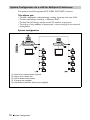
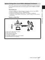
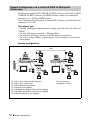
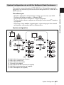
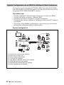
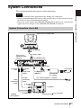
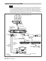
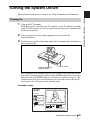
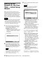
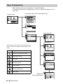
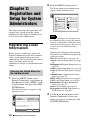
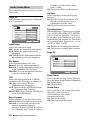
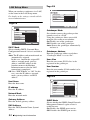
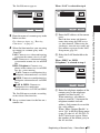
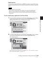
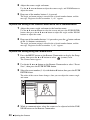
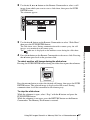
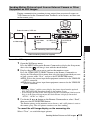
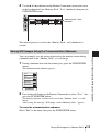
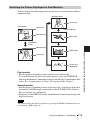
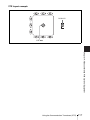
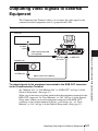
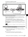
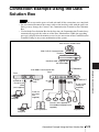
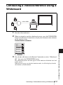
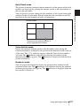
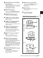
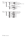
1
3-207-456-13 (1)
Video
Communication
System
Operating Instructions
Before operating the unit, please read this manual thoroughly and retain it for
future reference.
PCS-1/1P
© 2003 Sony Corporation
Owner’s Record
The model and the serial numbers are
located at the bottom. Record the serial
number in the space provided below. Refer
to these numbers whenever you call upon
your Sony dealer regarding this product.
Model No. PCS-1/1P
Serial No. ______________
WARNING
To prevent fire or shock hazard, do
not expose the unit to rain or
moisture.
To avoid electrical shock, do not
open the cabinet. Refer servicing to
qualified personnel only.
WARNING
This unit has no power switch.
When installing the unit, incorporate a
readily accessible disconnect device in the
fixed wiring, or connect the power cord to
socket-outlet which must be provided near
the unit and easily accessible.
If a fault should occur during operation of
the unit, operate the disconnect device to
switch the power supply off, or disconnect
the power cord.
IMPORTANT
The nameplate is located on the bottom.
For the customers in the USA
WARNING
Using this unit at a voltage other than 120 V
may require the use of a different line cord or
attachment plug, or both. To reduce the risk
of fire or electric shock, refer servicing to
qualified service personnel.
This device complies with Part 15 of the
FCC Rules.
2
Operation is subject to the following two
conditions: (1) This device may not cause
harmful interference, and (2) this device
must accept any interference received,
including interference that may cause
undesired operation.
This equipment has been tested and found to
comply with the limits for a Class A digital
device, pursuant to Part 15 of the FCC
Rules. These limits are designed to provide
reasonable protection against harmful
interference when the equipment is operated
in a commercial environment. This
equipment generates, uses and can radiate
radio frequency energy and, if not installed
and used in accordance with the instruction
manual, may cause harmful interference to
radio communications. Operation of this
equipment in a residential area is likely to
cause harmful interference in which case the
user will be required to correct the
interference at his own expense.
You are cautioned that any changes or
modifications not expressly approved in this
manual could void your authority to operate
this equipment.
The shielded interface cable recommended
in this manual must be used with this
equipment in order to comply with the limits
for a computing device pursuant to Subpart
B of Part 15 of FCC Rules.
This manual focuses on using ISDN lines
to conduct a videoconference, but it also
covers non-ISDN lines. If you use ISDN
lines, consult your Sony dealer for more
information.
• The ISDN service may not be available
in some areas.
Voor de klanten in Nederland
Dit apparaat bevat een vast ingebouwde
batterij die niet vervangen hoeft te worden
tijdens de levensduur van het apparaat.
Raadpleeg uw leverancier indien de batterij
toch vervangen moet worden.
De batterij mag alleen vervangen worden
door vakbekwaam servicepersoneel.
Gooi de batterij niet weg maar lever deze in
als klein chemisch afval (KCA).
Lever het apparaat aan het einde van de
levensduur in voor recycling, de batterij zal
dan op correcte wijze verwerkt worden.
If you dispose the unit, consult your nearest
Sony Service Center. The built-in battery
must be treated as a chemical waste.
For the customers in Canada
This Class A digital apparatus complies with
Canadian ICES-003.
3
Table of Contents
Chapter 1: Installation and
Preparation
Using This Manual ............................. 8
Features .............................................. 9
System Components ........................ 11
Basic System Components ......... 11
Optional Equipment ................... 12
System Configuration ...................... 14
System Configuration via a
LAN ................................ 14
System Configuration via an
ISDN ............................... 15
System Configuration via a LAN for
Multipoint Conference .... 16
System Configuration via an ISDN
for Multipoint
Conference ...................... 17
System Configuration via a LAN
and ISDN for Multipoint
Conference ...................... 18
System Configuration via a LAN for
Multipoint Data
Conference ...................... 19
System Configuration via an ISDN
for Multipoint Data
Conference ...................... 20
System Connections ......................... 21
System Connection via a LAN ... 21
System Connection via an ISDN 22
Preparing the System ....................... 23
Inserting Batteries into the Remote
Commander ..................... 23
Turning On/Off the TV Monitor
Together With the
Communication Terminal 24
Turning the System On/Off ............. 25
Turning On ................................. 25
Standby Mode Function ............. 26
4
Setting the Video Communication
System to Standby Mode .27
Turning Off .................................28
Adjusting the Volume on the TV
Monitor ............................28
Displaying the Help ....................29
Displaying the Versions and
Options ............................29
Setting Up the System for the First Time
— Initial Setup Wizard .....................30
Using the Menu ................................33
Operation ....................................33
Menu Configurations ..................34
Entering Characters ....................37
Chapter 2: Registration and
Setup for System
Administrators
Registering Local Information .........38
Opening the Setup Menu for the
Administrator ...................38
Dial Setup Menu .........................39
Answer Setup Menu ...................42
Multipoint Setup Menu ...............44
Audio Setup Menu ......................46
General Setup Menu ...................47
Administrator Setup Menu .........50
ISDN Setup Menu .......................51
SPID Setting for Customers in the
USA and Canada .............52
LAN Setup Menu ........................54
Machine Information Menu ........57
Status Menu ................................58
Encryption via LAN Menu .........60
Registering a Remote Party – Phone
Book ................................................60
Registering a New Remote Party 60
Changing the Contents of the Phone
Book ................................63
Deleting the Registered Remote
Party ................................63
Copying the Setting of the Phone
Book Menu ......................64
Creating a Private Phone Book ..64
Chapter 3: Daily
Videoconference
Starting a Conference by Calling a
Remote Party ....................................66
Turning on the Power .................66
Using the Launcher Menu ..........67
Selecting the Video/Audio Quality
Mode ...............................70
Calling a Remote Party ...............71
Receiving a Call from a Remote
Party ...............................................78
Answering a Call from a Remote
Party ................................78
Ending the Conference ...............80
Adjusting the Sound .........................81
Adjusting the Volume ................81
Cutting Off the Sound Momentarily
– Muting Function ...........81
Synchronizing Audio and Video
– Lip Sync Function ........82
Reducing Echo – Echo Canceler 82
Adjusting the Camera .......................83
Selecting the Camera to be
Controlled .......................83
Adjusting the Camera Angle and
Zoom ...............................84
Adjusting the Focus and
Brightness .......................86
Presetting the Angle and Zoom
Settings ............................87
Recalling the Preset Angle and
Zoom Setting .................. 89
Selecting the Input Picture and
Sound ............................................... 91
Switching the Displayed Picture
Between the Local and
Remote Pictures .............. 91
Selecting the Input Picture ......... 91
Switching the Picture Displayed on
the TV Monitor ............... 93
Switching the Sound to Be Sent to
the Remote Party ............ 93
Monitoring the Local Picture as a
Window Picture – PinP Feature ...... 94
Chapter 4: Videoconference
With Optional Equipment
Using Still Images Stored in a “Memory
Stick” for a Videoconference .......... 95
Displaying a Still Image Stored in a
“Memory Stick” .............. 95
Sending a Still Image Stored in a
“Memory Stick” .............. 98
About a “Memory Stick” ............... 100
Formatting a “Memory Stick” . 101
Sending Motion Pictures as Still
Images ............................................ 102
Sending Still Images Using the Still
Image Menu .................. 102
Sending a Still Image Using the
Communication
Submenu ....................... 103
Sending Motion Pictures Output
from a Document Stand as
Still Images ................... 104
Sending Motion Pictures Input from
an External Camera or Other
Equipment as Still
Images ........................... 105
Receiving Still Images from a Remote
Party ............................................. 106
5
Saving Still Images to a “Memory
Stick” ............................................. 107
Saving Still Images Using the Still
Image Menu .................. 107
Saving Still Images Using the
Memory Stick Menu ..... 108
Saving Still Images Using the
Communication
Submenu ....................... 109
Using a Convenient Menu Available
during Communication —
Communication Submenu .............. 110
Using Two Monitors – Dual
Monitor .......................................... 111
Switching the Picture Displayed on
Dual Monitors ............... 113
Using Multiple Microphones ......... 114
To connect the CTE-600
Communication
Transducer .....................131
Using Audio/Video Signal from the
Connected Equipment for a
Conference ......................................132
Setting Before Conferencing ....132
Operating the System During a
Conference .....................132
Displaying the Picture on a Projector or
Monitor ...........................................136
Outputting the Signal to One
Monitor ..........................136
Outputting the Signal to Two
Monitors ........................137
Using the Communication Transducer
(CTE) ............................................. 116
Chapter 6: Videoconference
Using a Whiteboard
Recording Audio During a
Conference ..................................... 118
Connection Example With a
Whiteboard .....................................139
Sending Audio/Video from the External
Equipment to a Remote Party ........ 119
Attaching the mimio Xi on the
Whiteboard .....................................140
Outputting Video Signals to External
Equipment ...................................... 121
Conducting a Videoconference Using a
Whiteboard .....................................141
Conducting a Conference Without the
Picture – Voice Meeting ................ 122
Controlling the Remote System With
the Tone Signal – DTMF
Transmission .................................. 123
Conducting a Data Conference Using
NetMeeting – T.120 Data
Conference ..................................... 124
Accessing the Communication
Terminal ......................................... 127
Using a Web Browser .............. 127
Using Telnet ............................. 127
Chapter 5: Data Conference
Connection Example Using the Data
Solution Box .................................. 129
6
Chapter 7: Encrypted
Videoconference via LAN
Preparing for an Encrypted
Videoconference via LAN ..............145
Starting an Encrypted Videoconference
via LAN ..........................................146
Chapter 8: Multipoint
Videoconference
Connection Examples for a Multipoint
Videoconference .............................148
Using the LAN Connection (Up to 6
Points) ............................148
Using the Cascade Connection via
LAN (Up to 10 Points) .. 149
Using the ISDN Connection ..... 150
Using the LAN & ISDN
connections ................... 152
Using the LAN & ISDN cascade
connection ..................... 153
Preparing for a multipoint
videoconference .............................154
Installing the MCU software .... 154
Setting the Multipoint Setup
Menu ............................. 156
Registering the Remote Parties in
the Multipoint Connection
List ................................157
Starting a Multipoint
Videoconference ............................161
Calling Remote Parties ............. 161
Receiving a Call from a Remote
Party .............................. 165
Using the Display Control ..............166
What is “Broadcast Mode”? ..... 166
Broadcast Modes and Displayed
Windows ....................... 168
Switching the Broadcast Mode . 169
Receiving the Broadcast Requested
From Any Other
Terminal ........................ 170
Ending the Multipoint
Videoconference ............................171
Notes on Secondary Terminals ...... 172
Connecting the External MCU .......173
Activating the Chair Control .... 173
Multipoint Attribute .......................176
Appendix
PCS-C1/C1P Camera Unit ....... 179
PCS-R1 Remote Commander .. 180
PCS-B768 ISDN Unit
(Optional) ..................... 182
PCS-DSB1 Data Solution Box
(Optional) ..................... 182
On Screen Messages ...................... 184
Troubleshooting ............................. 191
Specifications ................................ 195
PCS-P1/P1P Communication
Terminal ....................... 195
PCS-C1/C1P Camera Unit ....... 196
PCS-R1 Remote Commander .. 196
PCS-AC195 AC Adaptor ......... 196
PCS-A1 Microphone
(Optional) ..................... 196
PCS-A300 Microphone
(Optional) ..................... 197
PCS-B768 ISDN Unit
(Optional) ..................... 197
PCS-DSB1 Data Solution Box
(Optional) ..................... 197
PCS-320M1 H.320 MCU Software
(Optional) ..................... 197
PCS-323M1 H.323 MCU Software
(Optional) ..................... 197
Acceptable RGB Input/Output
Signals .......................... 198
Pin Assignment ........................ 200
Pin Assignment on Optional Board
Connectors .................... 202
Videoconferencing Room Layout . 203
Camera Range .......................... 203
Installing the Communication
Terminal and Camera ... 204
Glossary ......................................... 205
Menu Configuration ...................... 208
Location and Function of Parts and
Controls .......................................... 178
PCS-P1/P1P Communication
Terminal ........................ 178
7
Chapter 1:
Installation and
Preparation
Using This Manual
The chapters cover the following contents;
please read the chapters that may be required
for your type of videoconference.
Chapter 1: Installation and
Preparation
This chapter guides you through the system
configuration and information required to
use your Video Communication System for
the first time. It shows you how to install and
connect your Video Communication
System, to turn the system on/off and how to
access basic on-screen menus.
Chapter 2: Registration and Setup for
System Administrator
This chapter describes how to register and
set up all the necessary items for system
administrators, using the on-screen menus.
Chapter 3: Daily Videoconference
This chapter guides you through the basic
operations and settings to conduct a
videoconference. You will learn how to
conduct a conference from start to finish. It
is recommended that this chapter be read by
participants in the videoconference.
Chapter 4: Videoconference With
Optional Equipment
This chapter shows advanced
videoconferencing using the optional
equipment.
Chapter 5: Data Conference
This chapter shows you how to use the data
from a computer for the conference by using
the optional Data Solution Box.
8
Using This Manual
Chapter 6: Videoconference Using a
Whiteboard
This chapter shows how to use a whiteboard
with the mimio Xi* attached for a
videoconference.
* mimio® is a registered trademark of Virtual
Ink Corporation of the United States.
minio Xi is a trademark of Virtual Ink
Corporation of the United States.
Chapter 7: Encrypted
videoconference via LAN
This chapter shows how to conduct a
videoconference using an encrypted video
and audio data, and encrypted data from a
computer connected to the Data Solution
Box.
Chapter 8: Multipoint
Videoconference
This chapter shows you how to use the
Video Communication System to hold a
multipoint videoconference.
You need to install MCU software in this
System for a multipoint videoconference.
Appendix
This chapter contains description of the
controls and connectors on the components
of the Video Communication System,
message and troubleshooting lists,
specifications and glossaries.
Wide range of video/audio
compression format selectable
The PCS-1/1P Video Communication
System is a videoconferencing system that
provides natural, face-to-face
communications with a remote party by
transmitting and receiving images and sound
via LAN (Local Area Network) or ISDN
(Integrated Services Digital Network)
connections.
The Video Communication System supports
Interlaced SIF, H.264, MPEG4, H.263+,
H.263 and H.261 for video compression
format, and MPEG4 Audio, G.722.1,
G.722, G.729, G.728, G.723.1, G.711 for
audio compression format. You can choose
whether priority is given to video or audio
depending on the type of conference or
video/audio equipment used by a remote
party.
Supports ITU-T international
videoconferencing standard
The Video Communication System
complies with ITU-T Recommendations
defined by WTSC for easy connection with
remote parties overseas.
ITU: International Telecommunication
Union
WTSC: World Telecommunications
Standardization Committee
QoS (Quality of Service) function
for optimization of bandwidth and
traffic packet through network
“Packet Resend Request” and “Adaptive
Rate Control” functions incorporated,
allowing solution for busy network traffic or
packet loss, which provides consistent highquality communication.
Easy setup and operation
Supports data conferences
Use of the optional PCS-DSB1 Data
Solution Box allows the data from a personal
computer to be incorporated in the
presentation or to be shown on the projector.
Versatile use with a variety of
display units
The Help menu appears on the monitor
screen for guidance of operation. The menus
used for the system administrator or those
for conference participants are separately
displayed.
Supports multipoint conference
The Video Communication System is
compact size, allowing easy installation on a
TV. The camera and the Communication
Terminal can be separately installed,
allowing for greater flexibility when using a
large-size plasma display, projector screen,
etc.
Installing the optional PCS-323M1 H.323
MCU software (for LAN) or the PCS320M1 H.320 MCU software (for ISDN)
allows conduct of a multipoint conference.
The multipoint conference via LAN and
ISDN connections mixed is also available if
both the PCS-323M1 H.323 and PCS320M1 H.320 MCU software are installed in
a main Terminal.
High transmission speeds and
high-quality picture capability
Memory Stick slot equipped
The Video Communication System accepts
a LAN bandwidth of up to 1920 Kbps. It also
allows connection to as many as six ISDN
lines; 12B channels usable by using the
optional PCS-B768 ISDN Unit.
The Communication Terminal is equipped
with a Memory Stick slot, allowing the use
of still images recorded with a digital still
camera and stored in the “Memory Stick”.
Dual monitor system
Two monitors can be connected to the
Communication Terminal, enabling the use
Features
9
Chapter 1: Installation and Preparation
Features
of one monitor for motion pictures, and the
other monitor for pictures from a computer
or still images.
Supports an encrypted
videoconference (only for LAN
connection)
When you connect to other terminals via
LAN, you can start a videoconference only
with the terminals that enter the preset
password. This feature allows you to hold a
strictly confidential videoconference.
An encrypted conference among multiple
points or with cascade connection is enabled
if all the terminals are connected via LAN.
10
Features
System Components
Basic System Components
The PCS-1/1P Video Communication System is the basic system of the PCS1/1P Videoconferencing System. It contains the following components:
Unit
Description
PCS-P1/P1P Communication
Terminal
Contains the video codec, audio codec, echo
canceler, network interfaces and system controller.
PCS-C1/C1P Camera Unit
Composed of the camera and an integrated
microphone.
PCS-R1 Remote Commander
Used to operate the Communication Terminal and
Camera Unit.
PCS-AC195 AC adaptor
Supplies power to the Communication Terminal.
System Components
11
Chapter 1: Installation and Preparation
The PCS-1/1P Video Communication System is composed of basic system
components for a basic videoconference, and optional equipment for an
enhanced videoconference.
Optional Equipment
TV monitor
A TV or projector, etc. is required to monitor the images for videoconferencing
system.
Unit
Description
TV, Projector, etc.
Used as a monitor and speakers.
Optional equipment especially designed for use with the PCS-1/1P
The following optional devices are used to enhance your videoconference.
Unit
Description
PCS-B768 ISDN Unit
Used to connect to an ISDN line. Up to six ISDN
lines; 12B channels usable.
PCS-DSB1 Data Solution Box Use of this device allows easy connection with a
computer or projector for a data conference.
12
PCS-A1 Microphone
Omni-directional microphone that picks up sound
relatively from all directions, allowing participants to
speak from any location. It is recommended to use in
a quiet situation.
PCS-A300 Microphone
Unidirectional microphone. It is recommended when
you want to pick up the voice of a speaker directed
toward the microphone.
System Components
Description
PCS-DS150/DS150P
Document Stand
Allows transmission of pictures to the
Communication Terminal by infrared signals without
connecting a cable.
CTE-600 Communication
Transducer
Integrated microphone/speaker system suitable for
remote communication. The uni-directional
microphones pick up clear voice with minimum
background noise.
Moreover, the omni-directional speaker outputs
sound equally in all directions.
PCS-323M1 H.323 MCU
Software
Allows use for a multipoint videoconference over
LAN connection.
PCS-320M1 H.320 MCU
Software
Allows use for a multipoint videoconference over
ISDN connection.
Connecting cables
Use the following connecting cables to connect devices in this system.
PCS-1/1P Video Communication System
Cable
Part No.
Number
Camera cable (0.25 m (0.8 feet))
1-827-376-11
1
S-video connecting cable (1.5 m (4.9 feet))
1-776-078-42
1
Audio connecting cable (1 m (3.3 feet))
1-765-258-31
1
Camera cable
S-video connecting cable
Audio connecting cable
System Components
13
Chapter 1: Installation and Preparation
Unit
System Configuration
The PCS-1/1P Video Communication System has various system
configuration capabilities using the basic components and optional equipment.
This section describes seven typical examples.
System Configuration via a LAN
This allows you:
• To hold a point-to-point videoconference over LAN.
• To show still images stored in a “Memory Stick”.
System configuration
1
2
3
4
ON LINE
POWER
LAN ALERT
ON LINE
14
System Configuration
POWER
LAN ALERT
PCS-P1/P1P Communication Terminal
PCS-C1/C1P Camera Unit
PCS-R1 Remote Commander
TV monitor (not supplied)
System Configuration via an ISDN
Connection to ISDN is required to use the PCS-B768 ISDN Unit especially
designed for use with this system.
Chapter 1: Installation and Preparation
This allows you:
• To hold a point-to-point videoconference over ISDN.
• To show still images stored in a “Memory Stick”.
• To hold a videoconference with high speeds and highest quality image
transmission by connecting up to six ISDN lines.
System configuration
1
2
3
4
5
ON LINE
POWER
LAN ALERT
ON LINE
POWER
PCS-P1/P1P Communication Terminal
PCS-C1/C1P Camera Unit
PCS-R1 Remote Commander
TV monitor (not supplied)
PCS-B768 ISDN Unit (not supplied)
LAN ALERT
About the number of ISDN lines and B (bearer) channel
Up to six ISDN lines can be connected to one PCS-1/1P via the optional PCSB768 ISDN Unit. Each ISDN line is composed of two B channels that carry
data signals on the ISDN interface, enabling both channels to be used for one
ISDN line connection (2B connection), or each for a separate ISDN line
connection (1B connection). The more channels you use for a single
communication, the faster speeds and higher-quality picture you can obtain for
your network communication. You can connect up to six ISDN lines with the
PCS-1/1P and select the number of channels used for a single communication
among from 1B, 2B, 3B, 4B, 5B, 6B, 8B and 12B connections.
System Configuration
15
System Configuration via a LAN for Multipoint Conference
You need to install the optional PCS-323M1 H.323 MCU software.
This allows you:
• To hold a multipoint videoconference among up to ten sites over LAN.
• To show still images stored in a “Memory Stick”.
• To show the still images on the second TV monitor or projector.
• To pick up a large number of participants’ voices using up to two external
microphones.
System configuration
ON LINE
POWER
LAN ALERT
ON LINE
1
2
3
4
5
16
LAN ALERT
ON LINE
POWER
LAN ALERT
ON LINE
POWER
LAN ALERT
ON LINE
POWER
LAN ALERT
ON LINE
POWER
LAN ALERT
ON LINE
POWER
LAN ALERT
ON LINE
POWER
LAN ALERT
ON LINE
POWER
LAN ALERT
ON LINE
POWER
LAN ALERT
PCS-P1/P1P Communication Terminal
PCS-C1/C1P Camera Unit
PCS-R1 Remote Commander
TV monitor (not supplied)
PCS-323M1 H.323 MCU software (not supplied)
System Configuration
POWER
System Configuration via an ISDN for Multipoint Conference
You need to connect the optional PCS-B768 ISDN Unit especially designed
for use with this System and to install the optional PCS-320M1 H.320 MCU
software.
System configuration
ON LINE
POWER
LAN ALERT
ON LINE
ON LINE
POWER
POWER
LAN ALERT
LAN ALERT
ON LINE
1
2
3
4
5
ON LINE
ON LINE
1
2
3
4
5
6
POWER
LAN ALERT
6
POWER
POWER
LAN ALERT
LAN ALERT
PCS-P1/P1P Communication Terminal
PCS-C1/C1P Camera Unit
PCS-R1 Remote Commander
TV monitor (not supplied)
PCS-320M1 H.320 MCU software (not supplied)
PCS-B768 ISDN Unit (not supplied)
System Configuration
17
Chapter 1: Installation and Preparation
This allows you:
• To hold a multipoint videoconference among up to six sites over ISDN.
• To show still images stored in a “Memory Stick”.
• To show the still images on the second TV monitor or projector.
• To pick up a large number of participants’ voices using up to two external
microphones.
System Configuration via a LAN and ISDN for Multipoint
Conference
Installing the optional PCS-323M1 H.323 MCU software (for LAN) and PCS320M1 H.320 MCU software (for ISDN) enables conduct of a multipoint
conference via a LAN and ISDN mixed.
Two Communication Terminals in which MCU software is installed must be
connected via a LAN.
This allows you:
• To hold a multipoint videoconference among up to ten sites over LAN and
ISDN.
• To show still images stored in a “Memory Stick”.
• To show the still images on the second TV monitor or projector.
• To pick up a large number of participants’ voices using up to two external
microphones.
System configuration
LAN*
ON LINE
POWER
ON LINE
POWER
LAN ALERT
ON LINE
POWER
LAN ALERT
1
2
3
4
5
6
ON LINE
POWER
POWER
LAN ALERT
ON LINE
POWER
LAN ALERT
LAN ALERT
2
3
4
5
LAN ALERT
LAN ALERT
PCS-P1/P1P Communication Terminal
PCS-C1/C1P Camera Unit
PCS-R1 Remote Commander
TV monitor (not supplied)
PCS-323M1 H.323 MCU software (not supplied)
PCS-320M1 H.320 MCU software (not supplied)
PCS-B768 ISDN Unit (not supplied)
System Configuration
POWER
1
ON LINE
18
POWER
LAN ALERT
ON LINE
1
2
3
4
5
6
7
ON LINE
6
ON LINE
ON LINE
POWER
LAN ALERT
* Be sure to make a
connection via LAN.
POWER
LAN ALERT
System Configuration via a LAN for Multipoint Data Conference
You need to connect the optional PCS-DSB1 Data Solution Box especially
designed to use with this System and to install the optional PCS-323M1 H.323
MCU software.
System configuration
ON LINE
POWER
LAN ALERT
ON LINE
1
2
3
4
5
6
7
POWER
LAN ALERT
ON LINE
POWER
LAN ALERT
ON LINE
POWER
LAN ALERT
ON LINE
POWER
LAN ALERT
ON LINE
POWER
LAN ALERT
ON LINE
POWER
LAN ALERT
ON LINE
POWER
LAN ALERT
ON LINE
POWER
LAN ALERT
ON LINE
POWER
LAN ALERT
PCS-P1/P1P Communication Terminal
PCS-C1/C1P Camera Unit
PCS-R1 Remote Commander
TV monitor (not supplied)
PCS-323M1 H.323 MCU software (not supplied)
PCS-DSB1 Data Solution Box (not supplied)
PCS-A1 Microphone (not supplied)
System Configuration
19
Chapter 1: Installation and Preparation
This allows you:
• To hold a multipoint videoconference among up to ten sites over LAN.
• To show still images stored in a “Memory Stick”.
• To use the data from a computer or external equipment.
• To show the data from a computer or still images on the second TV monitor
or projector.
• To pick up a large number of participants’ voices using up to five external
microphones connected to the Data Solution Box.
System Configuration via an ISDN for Multipoint Data Conference
You need to connect the optional PCS-B768 ISDN Unit and the PCS-DSB1
Data Solution Box especially designed for use with this System and to install
the optional PCS-320M1 H.320 MCU software.
This allows you:
• To hold a multipoint videoconference among up to six sites over ISDN.
• To show still images stored in a “Memory Stick”.
• To use the data from a computer or an external equipment.
• To show the data from a computer or still images on the second TV monitor
or projector.
• To pick up a large number of participants’ voices using up to five external
microphones connected to the Data Solution Box.
System configuration
ON LINE
POWER
LAN ALERT
ON LINE
ON LINE
POWER
POWER
LAN ALERT
LAN ALERT
ON LINE
1
2
3
4
5
6
ON LINE
ON LINE
1
2
3
4
5
6
7
8
20
PCS-P1/P1P Communication Terminal
PCS-C1/C1P Camera Unit
PCS-R1 Remote Commander
TV monitor (not supplied)
PCS-320M1 H.320 MCU software (not supplied)
PCS-B768 ISDN Unit (not supplied)
PCS-DSB1 Data Solution Box (not supplied)
PCS-A1 Microphone (not supplied)
System Configuration
POWER
LAN ALERT
POWER
LAN ALERT
POWER
LAN ALERT
System Connections
This section describes the typical system connections.
Notes
System Connection via a LAN
PCS-C1/C1P Camera Unit
TERMINAL
VISCA OUT
to TERMINAL
Camera cable*
PCS-P1/P1P
Communication
Terminal
AUDIO OUT
AUX1–VIDEO IN–AUX2
to CAMERA UNIT
AUDIO IN
CAMERA UNIT
MIC
ISDN UNIT
(PLUG IN POWER)
1
2
WHITE
BOARD
(MIXED)
100BASE-TX
10BASE-T
VIDEO OUT
AUX
MAIN– MONITOR– SUB
RGB OUT
DC 19.5V
DSB
IR OUT
1
2
to DC19.5V
to AUDIO
OUT
Audio
connecting
cable*
to VIDEO
OUT
MONITOR
MAIN
S-video
connecting
cable*
Power cord*
to 100BASE-TX/
10BASE-T
PCS-AC195
AC adaptor
to a wall outlet
UTP cable (category 5, straight)**
to LAN
to S-video
input
TV monitor**
* supplied
** not supplied
to audio input
to a wall outlet
System Connections
21
Chapter 1: Installation and Preparation
• Be sure to turn off all the equipment before making any connections.
• Do not connect/disconnect the camera cable with the power on. Doing so may damage
the Camera Unit or Communication Terminal.
• For safety, do not connect the 100BASE-TX/10BASE-T connector to a network that
applies an excess voltage via the 100BASE-TX/10BASE-T connector.
System Connection via an ISDN
Notes
• Do not connect/disconnect the camera cable or the interface cable with the power on.
Doing so may damage the Camera Unit, Communication Terminal or ISDN Unit.
• Used with the PCS-B768 ISDN Unit for the first time, the Communication Terminal
may automatically upgrade the software of the ISDN Unit. While the upgrading
message is displayed on the monitor screen, be sure not to turn off the Communication
Terminal. Doing so may cause malfunction of the system.
PCS-C1/C1P Camera Unit
TERMINAL
VISCA OUT
to TERMINAL
Camera cable*
PCS-P1/P1P
Communication
Terminal
AUDIO OUT
AUX1–VIDEO IN–AUX2
to CAMERA UNIT
AUDIO IN
CAMERA UNIT
MIC
ISDN UNIT
(PLUG IN POWER)
1
2
WHITE
BOARD
(MIXED)
100BASE-TX
10BASE-T
VIDEO OUT
AUX
MAIN– MONITOR– SUB
RGB OUT
DC 19.5V
DSB
IR OUT
1
2
to DC19.5V
to AUDIO
OUT
to VIDEO
OUT
MONITOR
MAIN
to ISDN
UNIT
Power cord*
to a wall outlet
Interface cable
(supplied with the PCS-B768)
PCS-AC195
AC adaptor
to
TERMINAL
Front
1
Audio
connecting
cable*
S-video
connecting
cable*
PCS-B768 ISDN Unit**
TV monitor**
2
3
22
to audio input
System Connections
5
6
to ISDN 1-6
ISDN modular
cable**
to S-video
input
* supplied
** not supplied
4
to a wall outlet
to ISDN
Preparing the System
Inserting Batteries into the Remote Commander
1
Remove the battery compartment cover.
2
Insert two size AA (R6) batteries (supplied) with correct polarities into the
battery compartment.
Note
Be sure to insert the batteries E side first. Inserting them forcibly e side first may
damage the insulated film covering the batteries and cause a short circuit.
3
Replace the cover.
Battery life
When the Remote Commander does not function properly, replace both the
batteries with new ones.
Notes on batteries
To avoid damage from possible battery leakage or corrosion, observe the
following:
• Make sure to insert the batteries with the polarities in the correct direction.
• Do not mix old and new batteries, or different types of batteries.
• Do not attempt to charge the batteries.
• If you do not intend to use the Remote Commander for a long period of time,
remove the batteries.
• If battery leakage occurs, clean the battery compartment and replace all the
batteries with new ones.
Preparing the System
23
Chapter 1: Installation and Preparation
Most of the operations with the Video Communication System can be
controlled with the supplied Remote Commander.
Turning On/Off the TV Monitor Together With the Communication
Terminal
If you use a Sony TV, insert the IR repeater under the remote sensor of the TV.
Once you set the IR repeater, the TV will turn on or go to standby together with
the Communication Terminal when you press the "/1 button on the supplied
Remote Commander.
TV monitor
CAMERA UNIT
MIC
ISDN UNIT
(PLUG IN POWER)
1
2
100BASE-TX
10BASE-T
WHITE
BOARD
DC 19.5V
DSB
IR OUT
1
2
Remote sensor
IR repeater (supplied)
to IR OUT
Note
If the TV monitor is not turned on by pressing the @/1 button on the Remote
Commander, change the “IR Repeater Mode” setting in the General Setup menu.
For details on the “IR Repeater Mode” setting, see “General Setup Menu” on
page 49.
24
Preparing the System
Turning the System On/Off
This section describes how to turn on or off the Communication Terminal.
1
Turn on the TV monitor.
If the IR repeater is installed in the TV monitor, set the TV monitor to standby
mode. The TV monitor will turn on simultaneously when the Communication
Terminal is turned on.
2
Turn on the power of any other equipment to be used for the
videoconference.
3
Set the power switch on the right side of the Communication Terminal to
the on position (@).
POWER indicators
(Light in green.)
Power switch
The Communication Terminal turns on after a while. Three indicators on the
front of the Communication Terminal and the POWER indicator on the camera
light, then only the POWER indicators on both units remain on in green. The
launcher menu will appear on the monitor screen and the picture shot by the
local camera will also appear in the launcher menu.
Launcher menu
Connect
Phone Book
Dial
Menu
Angle Adj.
Press to show help
IP:0.0.0.0
Video:Main
ISDN:012345678912
Audio:MIC(INT)+AUX
Turning the System On/Off
25
Chapter 1: Installation and Preparation
Turning On
Notes
• After the power is turned on, the camera moves automatically for trial operation. Be
careful not to catch your finger.
• If you use force to prevent the camera moving, it may not resume moving and not
output a signal to the Communication Terminal. In this case, turn off the Terminal,
and turn it on again.
• When you turn on the power of the Communication Terminal for the first time after
installation, the setup wizard will appear after the self-diagnosis is completed. Set up
your system following the wizard.
For setups using the wizard, see “Setting Up the System for the First Time
— Initial Setup Wizard” on page 30.
• Used with an optional device especially designed for use with this system, such as the
Data Solution Box or ISDN Unit, for the first time, the Communication Terminal may
automatically upgrade the software of the connected device. While the upgrading
message is displayed on the monitor screen, be sure not to turn off the Communication
Terminal. Doing so may cause malfunction of the system. System malfunction may
also occur when a system power-off has been caused by an accidental problem such
as a power interruption during upgrading. If connection of the Data Solution Box or
ISDN Unit to the Communication Terminal is not re-established even after the system
power is recovered, consult a Sony dealer.
Standby Mode Function
To save power the Communication Terminal will enter standby mode if you
do not operate it for a specified period of time.
When the Communication Terminal is in standby mode, the POWER indicator
lights in orange. Once the Communication Terminal receives a call, the
standby mode is automatically released.
To release the standby mode
Press the @/1 button on the Remote Commander.
To specify the standby time
Specify the time that you want the system to remain on before entering into
standby mode (1 to 99 minutes) using “Standby Time” in the General Setup
menu. If you do not want the system to enter the standby mode, set “Standby
Mode” in the General Setup menu to “Off”.
For the “Standby Time” and “Standby Mode” settings, see “General Setup
Menu” on page 48.
Notes
• The POWER indicator on the camera goes off when the system enters standby mode.
• If you use a Sony TV monitor with the IR repeater installed under the remote sensor,
the TV monitor will enter standby mode together with the Communication Terminal.
26
Turning the System On/Off
Setting the Video Communication System to Standby Mode
You can turn on the Video Communication System with the @/1 button on the
Remote Commander if it is in standby mode.
Display the launcher menu on the monitor screen, then press the @/1 button
on the Remote Commander.
The message “Power off?” appears on the monitor screen.
2
Press the B or b button on the Remote Commander to select OK, and press
the PUSH ENTER button.
You may press the @/1 button on the Remote Commander.
POWER indicator (Not lit.)
POWER indicator (Lights in orange.)
@/1 button
B/b buttons and PUSH ENTER
button
The Video Communication System enters standby mode and the POWER
indicator on the Communication Terminal lights in orange. The POWER
indicator on the camera goes out.
If the IR repeater is installed in a Sony TV monitor, it will go into standby
together with the Video Communication System.
Note
When the Communication Terminal and the Camera are separately installed, point the
Remote Commander to the Camera for operations.
To cancel setting the system to standby
Select “Cancel” with the B or b button on the Remote Commander, then press
the PUSH ENTER button in step 2 above.
Turning the System On/Off
27
Chapter 1: Installation and Preparation
1
Turning Off
1
Set the power switch on the right side of the Communication Terminal to
the off position (a).
2
Turn off the power of other equipment used for the videoconference.
Note
Set the power switch on the Communication Terminal off when the system will not be
used for an extended period. While the power switch is off, you cannot receive a call
from a remote party.
Adjusting the Volume on the TV Monitor
Before adjusting the volume on the TV monitor, set the volume on the
Communication Terminal to the appropriate position.
1
Press the VOLUME +/– buttons on the Remote Commander to set the
volume level on the adjustment bar displayed on the screen to the middle
position.
2
Adjust the volume on the TV monitor so that you can properly hear a
remote party speaking.
To adjust the picture on the TV monitor
Use the controls on the TV monitor to adjust the picture, hue, contrast,
brightness or sharpness.
For details on picture adjustments, refer to the Operating Instructions of the
TV.
Note
Do not activate the TV’s surround sound feature as it cause strange sound since the echo
canceler of the Communication Terminal does not function properly.
28
Turning the System On/Off
Displaying the Help
Pressing the HELP button on the Remote Commander displays a balloon help
or a help screen to guide most operations on the monitor screen.
Displaying the Versions and Options
You can check the version of the Communication Terminal, versions of the
connected optional equipment for exclusive use of this system, and the options
installed in the Terminal by displaying the Machine Information menu on the
monitor screen.
For details on the Machine Information menu, see “Machine Information
Menu” on page 57.
Turning the System On/Off
29
Chapter 1: Installation and Preparation
Note
You can hide the balloon help used for entering characters.
Press the MENU button on the Remote Commander to show the menu, select
“Character Input Help” from the General Setup menu, and select “Off”. (See page 49.)
Setting Up the
System for the First
Time — Initial Setup
Wizard
3
Select a monitor from which signals
are output.
Note
If you select a monitor from “Monitor
Out”, other monitors than that you
selected display no menus.
Monitor Setup Wizard
When you turn on the Communication
Terminal for the first time after installation
and the self-diagnosis is completed, the
setup wizard appears on the monitor screen.
Register your local system data with the
setup wizard using the Remote Commander.
Dual Monitor
Off
Monitor Out
VIDEO OUT
Previous
Next
Cancel
Notes
• You can change the settings made with the
setup wizard later using the Setup menus.
• The setup wizard will also be displayed when
you install the PCS-B768 ISDN Unit to your
system later. Perform the setup again.
1
Select the language used for the onscreen menus and messages in the
Language Setup Wizard.
Language: Select one of eight
languages; English, French, German,
Japanese, Spanish, Italian, Chinese,
Portuguese.
Language Setup Wizard
Language
English
Next
2
Cancel
Use the V, v, B or b button on the
Remote Commander to select “Next”,
then press the PUSH ENTER button.
The Monitor Setup Wizard appears.
Note
Set this item only when you connect two or
more monitors with your System. If you
connect only one monitor TV, select
“Next”, then proceed to step 5.
30
Dual Monitor: When two monitors are
connected to the System, select
whether you use the dual monitor
mode to allow displaying motion
pictures on one monitor.
On: Enables the dual monitor mode. On
the second monitor still images,
images output from a computer or
captured images from a whiteboard.
Off: Disables the dual monitor mode.
For details on the dual monitor mode,
see see “Using Two Monitors – Dual
Monitor” on page 111.
Monitor Out (or Sub Monitor Out):
Select the output connected to the
monitor to which the signal is output.
This item changes to “Sub Monitor
Out” if “Dual Monitor” is set to “On”,
and selects the output connected to the
sub-monitor (second monitor) to
which the signal is output.
RGB OUT: Outputs from the RGB
OUT connector on the
Communication Terminal.
RGB OUT (DSB): Outputs from the
RGB OUT connector on the Data
Solution Box.
VIDEO OUT: Outputs from the
VIDEO OUT MONITOR MAIN or
SUB connector.
For details, see “Displaying the Picture
on a Projector or Monitor” on page 136.
Setting Up the System for the First Time — Initial Setup Wizard
4
Use the V, v, B or b button on the
Remote Commander to select “Next”,
then press the PUSH ENTER button.
Area Code: Enter the area code. Do not
enter the first “0” number.
Local Number: Enter the telephone
number.
5
When you select Auto SPID (only
for customers in the USA and
Canada)
You can automatically set up the Area
Code and Local Number on this page,
and SPID items in the SPID menu.
Set the following items on the ISDN
line.
Notes
• When you select a blank text box and
press the PUSH ENTER button on the
Remote Commander, the content in the
text box immediately above will be
copied to the selected text box.
• When 2-6 ISDN lines are used, enter the
telephone numbers in the B1 to F2 text
boxes in addition to the A1 and A2
boxes. To open the menu with D1 to F2
text boxes, select “Next”, then press the
PUSH ENTER button.
ISDN Setup Wizard
Country/Region
USA
Country/Region Code
1
Protocol
National ISDN
Previous
Next
Cancel
Country/Region: Select your country
or region.
Country/Region Code: Enter your
country code or region code with the
number buttons on the Remote
Commander.
Protocol: Select the protocol of the
ISDN line you are using.
6
Use the V, v, B or b button to select
“Next”, then press the PUSH ENTER
button.
7
Enter the telephone number of the
ISDN used by the system.
When you use one ISDN line, enter the
same number both in the A1 and A2 text
boxes (except for the USA and Canada).
8
Use the V, v, B or b button to select
“Next”, then press the PUSH ENTER
button.
9
Enter the sub-addresses.
Only numerals are available for a subaddress.
When you use one ISDN line, enter the
same number both in the A1 and A2 text
boxes (except for the USA and Canada).
Sub Address
A1
A2
B1
B2
C1
C2
Area Code
Local Number
A1
Previous
Next
Cancel
A2
B1
Note
B2
C1
C2
Previous
Next
Cancel
When 2-6 ISDN lines are used, enter the
sub-addresses in the B1 to F2 text boxes in
addition to the A1 and A2 boxes. To open
the menu with these text boxes, select
“Next”, then press the PUSH ENTER
button.
Setting Up the System for the First Time — Initial Setup Wizard
31
Chapter 1: Installation and Preparation
The ISDN Setup Wizard appears when
the PCS-B768 ISDN Unit is connected.
When the ISDN Unit is not connected,
the LAN Setup Wizard is displayed.
Proceed to step 11.
10Use the V, v, B or b button to select
“Next”, then press the PUSH ENTER
button.
For customers in other countries than
the USA and Canada
The LAN Setup Wizard appears.
For customers in the USA and
Canada
The ISDN Setup Wizard (SPID menu)
appears.
Set the SPID items, then select “Next”
and press the PUSH ENTER button.
The LAN Setup Wizard appears.
For details on the SPID settings, see
“SPID Setting for Customers in the USA
and Canada” on page 52.
Gateway Address: Enter your default
gateway address.
DNS Address: Enter your DNS
(Domain Name System) server
address.
Note
When you set “DHCP Mode” to “Auto”,
the assigned IP address is shown in the
launcher menu (page 67) or Machine
Information menu (page 57).
When you do not know how to set up the
LAN configuration, contact your
network administrator.
12Use the V, v, B or b button to select
“Next”, then press the PUSH ENTER
button.
The message window for confirmation
appears.
Note
When you do not use the LAN, select
“Next” to display the message window for
confirmation, then proceed to step 13.
11Set the following items on the LAN.
13Use the V, v, B or b button to select
“Save”, then press the PUSH ENTER
button.
LAN Setup Wizard
DHCP Mode
Save
Off
Host Name
Previous
IP Address
.
.
.
Network Mask
.
.
.
Gateway Address
.
.
.
DNS Address
.
.
.
Previous
Next
Cancel
DHCP Mode: Sets the DHCP
(Dynamic Host Configuration
Protocol).
Auto: Automatically assigns your IP
address, network mask, gateway
address and DNS address.
Off: Deactivates DHCP. In this case
set your IP address, network mask,
gateway address and DNS address
manually.
Host Name: Enter your host name.
IP Address: Enter your IP address.
Network Mask: Enter your network
mask.
32
Cancel
The settings are saved.
To cancel the setting
Press the V, v, B or b button to select
“Cancel”, then press the PUSH ENTER
button.
To go back to the previous wizard
Press the V, v, B or b button to select
“Previous”, then press the PUSH ENTER
button.
Setting Up the System for the First Time — Initial Setup Wizard
Using the Menu
3
Press the V or v button to select the
item you want to set or adjust, then
press the PUSH ENTER button.
The setting items are displayed.
The Video Communication System uses the
on-screen menus to make various
adjustments and settings. This section
describes how to adjust or set the items in the
menus and gives a brief introduction of the
menus.
Setup
Sound Priority
Multipoint Mode
Off
On
For the menu configuration, see page 208.
Keep pressing the [MENU] button to show
more detailed setup menus.
Save
Cancel
Operation
The basic operation through the menu is
explained by taking the Setup menu.
1
Press the MENU button on the
Remote Commander, or press the V,
v, B or b button to select “Menu” and
press the PUSH ENTER button in the
launcher menu.
4
Press the V or v button to select the
setting item you want, then press the
PUSH ENTER button.
5
Press the v button to select “Save”,
then press the PUSH ENTER button.
Setup
The Setup menu appears.
Setup
Video/Audio
Sound Priority
Multipoint Mode
Off
Video/Audio
Sound Priority
Multipoint Mode
On
Keep pressing the [MENU] button to show
more detailed setup menus.
Save
Cancel
Keep pressing the [MENU] button to show
more detailed setup menus.
Save
2
Cancel
Press the b button, then press the
PUSH ENTER button.
The selected setting is saved.
To return to the previous menu
Press the RETURN button on the Remote
Commander.
The top item is selected.
Setup
Video/Audio
Sound Priority
Multipoint Mode
Off
Keep pressing the [MENU] button to show
more detailed setup menus.
Save
Cancel
Using the Menu
33
Chapter 1: Installation and Preparation
Video/Audio
Menu Configurations
The menus of this system configure as described below.
For more detailed menu configurations, refer to “Menu Configuration” on
page 208.
Phone Book menu/Private Phone Book menu
Launcher menu
Phone Book
RECENT
Recent
LAN
Connect
Phone Book
TOKYO
Bob
John
LAN
ISDN
ISDN
OSAKA
NEW YORK
PARIS
0-9
A-I
Dial
J-S
T-Z
Menu
Angle Adj.
Press to show help
New Entry
IP:0.0.0.0
Video:Main
ISDN:012345678912
Audio:MIC(INT)+AUX
Dial menu
Dial
Line I/F
LAN
IP
LAN Bandwidth
1024 Kbps
More Options
Dial
Save
Menu
Still Image menu
Setup
Still Image
Send
Video/Audio
Sound Priority
Multipoint Mode
Off
Continuous Send
Clear
Save
Send Object
Keep pressing the [MENU] button to show
more detailed setup menus.
Save
Cancel
Camera menu
Camera
Preset Save
Selecting the icons on the menu tabs shown on
the left side of the launcher menu displays each
menu.
Icon
Preset Load
Adjustments
Displayed menu
Memory Stick menu
Returns to the previous menu.
Memory Stick
Phone Book menu
Dial menu
Setup menu
Still Image menu
Setup
Video/Audio
Sound Priority
Multipoint Mode
Off
Camera menu
Keep pressing the [MENU] button to show
more detailed setup menus.
Save
Memory Stick menu
Setup menu
Setup
Setup menu
(for the administrator)
Dial
Answer
Multipoint
Audio
General
Administrator
ISDN
LAN
Information
Status
Encryption via LAN
34
Using the Menu
Cancel
Launcher menu
Connect
Phone Book
Dial
Menu
Angle Adj.
Press to show help
IP:0.0.0.0
Video:Main
ISDN:012345678912
Audio:MIC(INT)+AUX
The launcher menu appears when the Video
Communication System is turned on or is
displayed while it is not connected to a
remote party.
For details on the launcher menu, see pages
67 to 69.
For details on the Dial menu, see pages 71
to 75.
Still Image menu
Still Image
Send
Continuous Send
Clear
Save
Send Object
Phone Book menu
Phone Book
RECENT
Recent
LAN
TOKYO
Bob
John
0-9
A-I
J-S
T-Z
LAN
ISDN
ISDN
OSAKA
NEW YORK
PARIS
New Entry
The Phone Book menu is used to register a
remote party, or to call a registered remote
party.
The menu appears when you select “Phone
Book” in the Launcher menu or
from
the menu tabs.
The Still Image menu is used to control still
images.
The menu appears when you select
from the menu tabs displayed by selecting
“Menu” in the launcher menu.
For details on the Still Image menu, see
pages 102 to 109.
Camera Menu
Camera
Preset Save
Preset Load
Adjustments
For details on the Phone Book menu, see
pages 60 to 64 and 75 to 77.
Dial menu
Dial
Line I/F
LAN
IP
LAN Bandwidth
1024 Kbps
The Camera menu is used to adjust camera
angle or zooming of the displayed image.
The menu appears when you select
from the menu tabs displayed by selecting
“Menu” in the launcher menu.
For details on the Camera menu, see pages
83 to 90.
More Options
Dial
Save
Using the Menu
35
Chapter 1: Installation and Preparation
The Dial menu is used to call a remote party
who is not registered in the Phone Book.
The menu appears when you select “Dial” in
the launcher menu or
from the menu
tabs, or press the CONNECT/
DISCONNECT (
/ ) button on the
Remote Commander.
Memory Stick menu
Setup menu (for the administrator)
Memory Stick
Setup
Dial
Answer
Multipoint
Audio
General
Administrator
ISDN
LAN
Information
Status
Encryption via LAN
The Memory Stick menu is used when you
are using a “Memory Stick”. The menu is
not displayed unless a “Memory Stick” is
installed in the Communication Terminal.
The menu appears when you select
from
the menu tabs displayed by selecting
“Menu” in the launcher menu.
The Setup menu for the administrator is used
to set various detailed items on the system.
The menu can be displayed by keeping the
MENU button on the Remote Commander
pressed.
For details on the Memory Stick menu, see
pages 95 to 99 and page 108.
You can also display the Setup menu for the
administrator by pressing the numeric button
9 on the Remote Commander twice while
the Setup menu (Initial Setup) or the screen
in communication is displayed.
Setup menu
Note
Setup
Video/Audio
Sound Priority
Multipoint Mode
Off
For details on the Setup menu (for the
administrator), see pages 38 to 60.
Keep pressing the [MENU] button to show
more detailed setup menus.
Save
Cancel
The Setup menu is used for participants in
the videoconference before or during the
conference.
The menu appears when you select
from
the menu tabs displayed by selecting
“Menu” in the launcher menu or by pressing
the MENU button on the Remote
Commander.
For details on the Setup menu, see pages 70
and 71.
36
Using the Menu
desired symbol. Pressing the 0 button also
enables you to enter the symbol, –, “ or ”.
Entering Characters
This section explains how to enter the
letters, numerals or symbols on the text box
in the menu using the Remote Commander.
VOLUME
ZOOM
DISPLAY
VIDEOINPUT
SELECT
CLEAR
SYMBOL
PinP
FAR/NEAR
BACK
SPACE
ALPHA/
NUM
VIDEO INPUT
SELECT (SYMBOL)
button
FAR/NEAR
(ALPHA/NUM)
button
PUSH
ENTER
RETURN
DISPLAY (CLEAR)
button
MENU
CONNECT/
DISCONNECT
PinP (BACK
SPACE) button
To delete a character
Press the PinP (BACK SPACE) button. The
last entered character is deleted.
To delete all characters in a line
Move the cursor to the line to be deleted,
then press the DISPLAY (CLEAR) button.
Note
When you press the HELP button on the
Remote Commander to show balloon helps or
help screens, you can hide only the balloon
help used for entering characters.
Select “Character Input Help” from the
General Setup menu, then select “Off”. (See
page 49.)
Number buttons
(dot) button
HELP
PCS-R1
To enter letters or numerals
1
Press the FAR/NEAR (ALPHA/
NUM) button repeatedly to enable the
alphabet or numerals to be input.
2
Press the number buttons repeatedly to
enter the letters or numerals you want.
You can enter the letter shown on each
button by pressing it repeatedly.
You can enter the numeral shown on
each button by pressing it.
To enter a symbol
Press the VIDEO INPUT SELECT
(SYMBOL) button repeatedly to select the
Using the Menu
37
Chapter 1: Installation and Preparation
MIC
ON/OFF
To enter a dot (.) for an IP address
Press the
button.
Chapter 2:
Registration and
Setup for System
Administrators
2
Keep the MENU button pressed.
The Setup menu for the administrator
appears on the monitor screen.
Setup
Dial
Answer
Multipoint
Audio
General
Administrator
ISDN
LAN
Information
Status
Encryption via LAN
This chapter describes the registration and
settings to be carried out by the system
administrator.The chapter is intended to be
read by the system administrator.
Note
You can also display the Setup menu for
the administrator by pressing the numeric
button 9 on the Remote Commander twice
while the initial Setup menu (shown in step
1) or the screen in communication is
displayed.
Registering Local
Information
Choosing the following items from the
Setup menu for Administrator opens the
respective menus.
Dial: Dial Setup menu (see page 39)
Answer: Answer Setup menu (see page
42)
Multipoint: Multipoint Setup menu (see
page 44)
Audio: Audio Setup menu (see page 46)
General: General Setup menu (see page
47)
Administrator: Administrator Setup
menu (see page 50)
ISDN: ISDN Setup menu (see page 51)
LAN: LAN Setup menu (see page 54)
Information: Machine Information
menu (see page 57)
Status: Status menu (see page 58)
Encryption via LAN: Encryption via
LAN menu (see page 60)
Before starting a conference, register the
required information on the local terminals
of the system using the Setup menu for
administrator. This section describes how to
display the Setup menus for the
administrator and gives a introduction to the
menus.
Opening the Setup Menu for
the Administrator
1
Press the MENU button on the
Remote Commander, or use the V, v,
B or b button to select “MENU” in the
launcher menu, then press the PUSH
ENTER button.
The initial Setup menu appears on the
monitor screen.
3
Setup
Video/Audio
Sound Priority
Multipoint Mode
Off
Keep pressing the [MENU] button to show
more detailed setup menus.
Save
38
Cancel
Registering Local Information
Use the V, v, B or b button on the
Remote Commander to select the
menu you want to set, then press the
PUSH ENTER button.
The selected setup menu appears.
Dial Setup Menu
Dial Setup
The Dial Setup menu is used to set the
attributes for dialing.
Page: 1/4
Line I/F
LAN
Bonding
Auto
Number of Lines
12B
LAN Bandwidth
1024 Kbps
Prefix
Prefix-None
Restrict
Auto
Page 1/4
Save
Cancel
Line I/F
Set the respective items.
For details on individual items, see the
relevant menu pages.
5
After the setting is completed, use the
V, v, B or b button to select “Save”,
then press the PUSH ENTER button.
The setting is saved, and the Setup menu
is restored.
To cancel the setup
Use the V, v, B or b button on the Remote
Commander to select “Cancel”, then press
the PUSH ENTER button. Or press the
RETURN button on the Remote
Commander.
To page up or down the selected
menu
Use the V, v, B or b button on the Remote
Commander to select the Page box, then
press the b button to advance the page and
the B button to go back to the previous page.
LAN
Bonding
Auto
Number of Lines
12B
LAN Bandwidth
1024 Kbps
Prefix
Prefix-None
Restrict
Auto
Save
Cancel
Line I/F
Select the line interface you use normally.
LAN: Connects a videoconferencing system
via a LAN.
ISDN: Connects a videoconferencing
system via ISDN.
ISDN (Telephone): Connects an audio-only
telephone via ISDN (Voice Meeting).
Bonding*
Select whether you use a process called
BONDING to connect multiple ISDN lines.
Through BONDING, connection of one line
enables you to automatically connect all
other lines.
Auto: Automatically activates connection
through BONDING if this feature is
available on the remote party.
On: Always connects a remote party
through BONDING.
*
Bonding (Bandwidth on Demand
Interoperability Group) is a registered
trademark of THE BONDING
CONSORTIUM.
Number of Lines
Selects the number of ISDN channels to be
used for BONDING call.
You can select from among 1B, 2B, 3B, 4B,
5B, 6B, 8B and 12B channels.
LAN Bandwidth
Selects the bandwidth to be used when
connected to a LAN.
Registering Local Information
39
Chapter 2: Registration and Setup for System Administrators
4
Dial Setup
Page: 1/4
You can select from among 64 Kbps, 128
Kbps, 384 Kbps, 768 Kbps, 1024 Kbps,
1920 Kbps and “Other”. When “Other” is
selected, a bandwidth value between 1 and
1920 Kbps can be entered.
Prefix
Selects the prefix number (call number
prefixed to a line number) setting.
Prefix-None: Sets when using no prefix
number.
Prefix-A: Selects to use the prefix set in
“Prefix-A” on Page 3 of the Dial Setup
menu.
Prefix-B: Selects to use the prefix set in
“Prefix-B” on Page 3 of the Dial Setup
menu.
Prefix-C: Selects to use the prefix set in
“Prefix-C” on Page 3 of the Dial Setup
menu.
For details on setting the prefix number, see
Page 3 of the Dial Setup Menu on page 41.
Restrict
Selects the ISDN transmission rate at
dialing.
Auto: Selects when connecting a remote
party via a normal ISDN line.
56K: Selects when connecting a remote
party in a region or country where the
ISDN transmission rate is 56 Kbps.
Note
The system is set to connect an ISDN line at the
transmission rate of 64 Kbps at the factory.
However, some countries such as the USA or
some regions may use the ISDN transmission
rate of 64 Kbps and 56 Kbps. You may not
communicate with such country or region with
the transmission rate of 64 Kbps. In this case,
set “Restrict” to “56K” before dialing.
Page 2/4
Dial Setup
Page: 2/4
Video Mode
ALL
Video Frame
15fps
Audio Mode
ALL
Far End Camera Control
On
T.120 Data
Off
Save
Cancel
Video Mode
Selects the compression format of the
pictures to be sent to a remote party.
ALL: Sends pictures of any compression
format depending on the format used on
the remote site.
Interlaced SIF: Sends pictures based on the
SIF 50/60fps format.
H.264: Sends pictures based on
Recommendation H.264.
MPEG4: Sends pictures based on the
MPEG4 format.
H.263+: Sends pictures based on
Recommendation H.263+.
H.261: Sends pictures based on
Recommendation H.261 (when sending
still images using Annex D).
Note
The Interlaced SIF format is not available if the
videoconferencing system of the connected
terminal has a different color system.
Video Frame
Selects the number of video frame for
transmission.
15fps: Sends CIF format pictures at a
maximum rate of 15 frames per second.
30fps: Sends CIF format pictures at a
maximum rate of 30 frames per second.
Note
When an encrypted videoconference is
conducted and a computer picture is received
with “Monitor Out” set to “RGB OUT”, the
number of video frame may decrease.
40
Registering Local Information
Note
When the remote videoconferencing system
does not support the Audio Mode selected by
the local site, the mode automatically switches
to “G.711”.
Far End Camera Control
When the conference starts by calling a
remote party from the local site, selects
whether to enable control of each other’s
cameras from each other sites.
On: Enables control of each other’s
cameras. Normally, set to ON.
Off: Disables control of each other’s
cameras.
T.120 Data
Selects whether you conduct a data
conference via the T.120 standard using
NetMeeting (only for the ISDN connection).
On: Enables conduct of the T.120 data
conference.
Off: Disables conduct of the T.120 data
conference.
For details on the T.120 data conference,
see “Conducting a Data Conference Using
NetMeeting – T.120 Data Conference” on
page 124.
Page 3/4
Dial Setup
Page: 3/4
Prefix-A
Prefix-B
Prefix-C
Save
Cancel
Prefix-A
When “Prefix” on Page 1 of the Dial Setup
menu is set to “Prefix-A”, the line number
prefixed by the prefix (dial number)
registered in this box is dialed.
Prefix-B
When “Prefix” on Page 1 of the Dial Setup
menu is set to “Prefix-B”, the line number
prefixed by the prefix (dial number)
registered in this box is dialed.
Prefix-C
When “Prefix” on Page 1 of the Dial Setup
menu is set to “Prefix-C”, the line number
prefixed by the prefix (dial number)
registered in this box is dialed.
Note
Enter “9” when this is required to reach an
outgoing call.
Page 4/4
Dial Setup
Page: 4/4
Telephone Mode
Auto
More Options Enable
Off
User Name Input
Off
Save
Cancel
Telephone Mode
Selects the audio compression format when
conducting a voice meeting.
Auto: Selects an appropriate format
automatically.
Registering Local Information
41
Chapter 2: Registration and Setup for System Administrators
Audio Mode
Selects the compression format of audio to
be sent to a remote party.
ALL: Sends any audio compression format
depending on the format used on the
remote site.
MPEG4 Audio: Sends audio based on the
MPEG4 format.
G.722.1: Sends audio based on the G.722.1
standard.
G.722: Sends audio based on the G.722
standard.
G.729: Sends audio based on the G.729
standard.
G.728: Sends audio based on the G.728
standard.
G.723.1: Sends audio based on the G.723.1
standard.
G.711: Sends audio based on the G.711
standard.
G.711 µ-law: Selects the format based on
the G.711 µ-law standard.
G.711 A-law: Selects the format based on
the G.711 A-law standard.
More Options Enable
Selects whether you set the items in the Dial
Setup menu for each dial list.
On: Enables setting for each dial list. When
you select “More Options Enable” in the
List Edit menu of the Phone Book, the
Dial Setup menu appears.
Off: Enables application of the settings in
the Dial Setup menu to all the dial lists.
User Name Input
Before starting communication, selects
whether you record the user names in the
communication log.
On: Records the user names. Each time a
dialing is made, the menu where the
name is input appears.
Off: Disables recording of the user names.
Answer Setup Menu
The Answer Setup menu is used to set up for
receiving a call.
Page 1/2
Answer Setup
Page: 1/2
Auto Answer
ISDN
Auto Answer
Number of Lines
12B
Restrict
Auto
LAN Bandwidth
1024 Kbps
ISDN MSN
Off
Save
Cancel
Auto Answer
Selects whether the auto answer mode is
activated.
Auto Answer: Answers a call in auto
answer mode. When a call comes in, the
line is automatically connected.
Off: Answers a call in manual answer mode.
When you are called up, the phone rings.
If you select “OK” for the message
“Respond?”, the line is connected.
Number of Lines
Selects the number of ISDN channels used
to receive a call.
You can select from among 1B, 2B, 3B, 4B,
5B, 6B, 8B and 12B channels.
Restrict
Selects the transmission rate of the ISDN
lines when a call comes in.
Auto: Selects when connecting a remote
party via a normal ISDN line.
56 K: Selects when connecting a remote
party in a region or country where 56
Kbps is used for the ISDN transmission
rate.
Note
The system is set to connect an ISDN line at the
transmission rate of 64 Kbps at the factory.
However, some countries such as the USA or
some regions may use the ISDN transmission
rate of 64 Kbps and 56 Kbps. You may not
communicate with such country or region with
42
Registering Local Information
the transmission rate of 64 Kbps. In this case,
set “Restrict” to “56K” before dialing.
LAN Bandwidth
Select the bandwidth to be used when
connected to a LAN.
You can select from among 64 Kbps, 128
Kbps, 384 Kbps, 768 Kbps, 1024 Kbps,
1920 Kbps and “Other”.
When “Other” is selected, a bandwidth value
between 1 and 1920 Kbps can be entered.
Page 2/2
Answer Setup
Page: 2/2
Video Mode
ISDN
ALL
Video Frame
15fps
Audio Mode
ALL
Far End Camera Control
On
T.120 Data
Off
Audio Mode
Selects the compression format of audio to
be received from a remote party.
ALL: Receives any audio compression
format depending on the format used on
the remote site.
MPEG4 Audio: Receives audio based on
the MPEG4 format.
G.722.1: Receives audio based on the
G.722.1 standard.
G.722: Receives audio based on the G.722
standard.
G.729: Receives audio based on the G.729
standard.
G.728: Receives audio based on the G.728
standard.
G.723.1: Receives audio based on the
G.723.1 standard.
G.711: Receives audio based on the G.711
standard.
Note
Save
Cancel
Video Mode
Selects the compression format of the
pictures to be received from a remote party.
ALL: Receives pictures of any compression
format depending on the format used on
the remote site.
Interlaced SIF: Receives pictures based on
the SIF 50/60fps format.
H.264: Receives pictures based on
Recommendation H.264.
MPEG4: Receives pictures based on the
MPEG4 format.
H.263+: Receives pictures based on
Recommendation H.263+.
H.261: Receives pictures based on
Recommendation H.261.
Note
The Interlaced SIF format is not available if the
videoconferencing system of the connected
terminal has a different color system.
When the remote videoconferencing system
does not support the Audio Mode selected by
the local site, the mode automatically switches
to “G.711”.
Far End Camera Control
When the conference starts with a call from
a remote party, selects whether to enable
control of each other’s cameras from each
other’s sites.
On: Enables control of each other’s
cameras.
Off: Disables control of the remote party’s
camera.
T.120 Data
Selects whether you conduct a data
conference via the T.120 standard using
NetMeeting (only for the ISDN connection).
On: Enables conduct of the T.120 data
conference.
Off: Disables conduct of the T.120 data
conference.
Registering Local Information
43
Chapter 2: Registration and Setup for System Administrators
ISDN MSN
Selects whether you are using the Multiple
Subscriber Number.
On: Selects when you use the Multiple
Subscriber Number.
Off: Selects when you do not use the
Multiple Subscriber Number.
Video Frame
Selects the number of video frame to be
received.
15 fps: Receives CIF format pictures at a
maximum rate of 15 frames per second.
30 fps: Receives CIF format pictures at a
maximum rate of 30 frames per second.
For details on the T.120 data conference,
see “Conducting a Data Conference Using
NetMeeting – T.120 Data Conference” on
page 124.
Multipoint Setup Menu
The Multipoint Setup menu is used when
you conduct a multipoint videoconference.
Note
The Multipoint Setup menu is available when
the System has the optional PCS-320M1 H.320
MCU or PCS-323M1 H.323 MCU software
installed.
Page 1/2
Multipoint Setup
Page: 1/2
Multipoint Mode
ISDN
Off
Broadcast Mode
Split
Number of Lines
2Bx5
Total LAN Bandwidth
1024 Kbps
Restrict
Auto
Save
Cancel
Multipoint Mode
Selects whether you conduct a multipoint
videoconference.
On: Conducts a multipoint
videoconference.
Off: Does not conduct a multipoint
videoconference.
Note
The Multipoint Mode can be selected with the
initial Setup menu (page 70).
Broadcast Mode
Selects the broadcast mode.
Split: Displays the pictures of the terminals
connected in split windows.
Voice Activate: Detects the terminal with
the speaker with the loudest voice, and
sends the picture of that terminal to all
other terminals.
Number of Lines
Selects the ISDN channels and the number
of remote points to be used for a multipoint
videoconference.
1B × 5: Connects to five points via a 1B
channel. (Six-point conference)
44
Registering Local Information
2B × 5: Connects to five points via 2B
channels. (Six-point conference)
4B × 3: Connects to three points via 4B
channels. (Four-point conference)
6B × 2: Connects to two points via 6B
channels. (Three-point conference)
Note
Some of the above items are not available
depending on the number of ISDN lines you
are using.
Restrict
Selects the ISDN transmission rate when
dialing or answering.
Auto: Selects when connecting a remote
party via a normal ISDN line.
56K: Selects when connecting a remote
party in a region or country where the
ISDN transmission rate is 56 Kbps.
Note
The system is set to connect an ISDN line at the
transmission rate of 64 Kbps at the factory.
However, some countries such as the USA or
some regions may use the ISDN transmission
rate of 64 Kbps and 56 Kbps. You may not
communicate with such country or region with
the transmission rate of 64 Kbps. In this case,
set “Restrict” to “56K” before dialing.
Page 2/2
ALL
Audio Mode
ALL
Display Terminal Name
On
Far End Camera Control
On
Reject Answer
Off
Note
When the remote videoconferencing system
does not support the Audio Mode selected by
the local site, the mode automatically switches
to “G.711”.
Display Terminal Name
Selects whether you display the connected
terminal names on the monitor screen at the
time of disconnection.
On: Displays the terminal names.
Off: Does not display terminal names.
Far End Camera Control
Selects whether to enable control of each
other’s cameras from each other sites.
On: Enables control of each other’s
cameras. Normally, set to ON.
Off: Disables control of each other’s
cameras.
Reject Answer
Selects whether to disable connection to a
remote party who is calling during a
multipoint videoconference.
On: Disables connection to a remote party.
Off: Enables connection to a remote party.
Multipoint Setup
Page: 2/2
Video Mode
Audio Mode
Selects the audio compression format for a
multipoint conference.
ALL: Uses any audio compression format
depending on the format used on the
remote site.
G.722: Uses audio based on the G.722
standard.
G.728: Uses audio based on the G.728
standard.
G.711: Uses audio based on the G.711
standard.
Save
Cancel
Video Mode
Selects the compression format of the
pictures for a multipoint conference.
Registering Local Information
45
Chapter 2: Registration and Setup for System Administrators
Total LAN Bandwidth
Selects the total bandwidth to be used for a
multipoint videoconference via LAN.
You can select from among 384 Kbps, 768
Kbps, 1024 Kbps, 1920 Kbps and “Other”.
When “Other” is selected, a bandwidth value
between 1 and 1920 Kbps can be entered.
ALL: Uses any video compression format
depending on the format used on the
remote sites.
H.263: Uses pictures based on
Recommendation H.263.
H.261: Uses pictures based on
Recommendation H.261.
Audio Setup Menu
The Audio Setup menu is used to set various
audio items.
Page 1/2
The level meter indicating the audio input
level is displayed.
Audio Setup
Page: 1/2
Input Select
MIC
Mic Select
Internal
CTE
Off
Echo Canceler
Internal
Lip Sync
Off
Recording Mute
On
Save
Cancel
Input Select
Selects the sound to be input.
MIC: Inputs the sound of the microphone.
AUX: Inputs the sound from external
equipment.
MIC+AUX: Inputs both sounds from the
microphone and external equipment.
Mic Select
Selects the microphone to be used.
Internal: Uses the built-in microphone.
External: Uses the microphone connected
to the Communication Terminal.
DSB MIC: Uses the microphone connected
to the Data Solution Box.
CTE
Selects the input to which the CTE-600
Communication Transducer is connected.
Off: Does not use the CTE-600
Communication Transducer.
AUX: Inputs from the AUDIO IN jack on
the Communication Terminal.
DSB AUX IN: Inputs from the AUX IN jack
on the Data Solution box.
Echo Canceler
Selects whether you use the echo canceler.
Internal: Enables the built-in echo canceler.
External: Uses the echo canceler of the
external equipment connected.
The input from the AUDIO IN jack on
the Communication Terminal is always
46
Registering Local Information
available regardless of the “Input
Select” setting.
Off: Disables the built-in echo canceler.
Lip Sync
Selects whether to enable the Lip Sync
function.
On: Enables the Lip Sync function. The
movement of the speaker’s lips is
synchronized with his voice.
Off: Disables the Lip Sync function.
Recording Mute
When connecting a video cassette recorder
to the AUDIO IN/AUDIO OUT (MIXED)
jacks to record the sound for a conference,
the recording mute function prevents echo
from reflecting on a remote site. This item is
only available when “Input Select” is set to
“AUX” or “MIC + AUX”.
On: Enables the recording mute function.
Off: Disables the recording mute function.
Page 2/2
Audio Setup
Page: 2/2
Beep Sound
On
Sound Effect
On
Dial Tone
On
Ringer Tone
On
Save
Cancel
Beep Sound
Selects whether the beep sounds when you
press the button on the Remote Commander.
On: Enables beep.
Off: Disables beep.
Sound Effect
Selects whether or not to output the sound
when the system starts up, a
videoconference starts, or the
videoconference ends.
On: Outputs the sound.
Off: Does not output the sound.
Dial Tone
Selects whether or not to output a ring-back
tone and busy tone when you are dialing.
On: Outputs the dial tone.
Off: Does not output the dial tone.
Ringer Tone
Selects whether or not to output a ringer tone
when you receive a call.
On: Outputs the ringer tone.
Off: Does not output the ringer tone.
General Setup Menu
Page 1/4
General Setup
Page: 1/4
Terminal Name
PCS-1ISDN
Dual Monitor
Off
Monitor Out
VIDEO OUT
Standby Mode
On
Standby Time
30 minutes
Time Display
On
Cancel
Terminal Name
Input the terminal name to report when the
system is connected to the external
multipoint videoconferencing system.
Dual Monitor
When two monitors are connected to the
System, selects whether you use the dual
monitor mode.
On: Enables the dual monitor mode. Still
images are always displayed on the
second monitor.
Off: Disables the dual monitor mode. Still
images are always displayed on the first
monitor.
For details on the dual monitor mode, see
“Using Two Monitors – Dual Monitor” on
page 111.
Monitor Out (or Sub Monitor Out)
Selects the output connected to the monitor
to which the signal is output.
This item changes to “Sub Monitor Out” if
“Dual Monitor” is set to “On”, and selects
the output connected to the sub-monitor
(second monitor) to which the signal is
output.
RGB OUT: Outputs from the RGB OUT
connector on the Communication
Terminal.
RGB OUT (DSB): Outputs from the RGB
OUT connector on the Data Solution
Box.
VIDEO OUT: Outputs from the VIDEO
OUT MONITOR MAIN or SUB
connector.
For details, see “Displaying the Picture on
a Projector or Monitor” on page 136.
Registering Local Information
47
Chapter 2: Registration and Setup for System Administrators
Save
Standby Mode
Sets whether the Communication Terminal
is set to standby mode if it is not operated for
a specified period of time.
On: Activates standby mode.
Off: Deactivates standby mode.
Standby Time
Specifies the time that the system remains on
before entering the standby mode. You can
specify a time between 1 and 99 minutes.
For details on standby mode, see “Standby
Mode Function” on page 26.
Time Display
Selects whether you display the elapsed time
on the monitor screen during the conference.
On: Displays the elapsed time.
Off: Does not display the elapsed time.
Note
During communication, some items are not
displayed.
Page 2/4
General Setup
Page: 2/4
Clock Set
MM/DD/YYYY
HH:MM:SS
11/30/2003
19:25:53
Last Number Registration
T.120 PC Address
On
.
Whiteboard Attachment
Vertical
Whiteboard Size
3'0"x4'0"
Whiteboard Size Measurement
Inches
.
.
Save
Cancel
Clock Set
Enter the current date and time.
Last Number Registration
Selects whether or not to register the remote
party in the Phone Book after the conference
has finished.
On: If the remote party has not yet been
registered in the Phone Book, the
message “Register this participant in the
list?” appears on the monitor screen after
the conference has finished. When you
select “OK”, the List Edit menu opens.
Off: The above message does not appear.
48
Registering Local Information
T.120 PC Address
When conducting a data conference based
on the T.120 standard using NetMeeting,
input the IP address of the computer (for the
ISDN connection).
For details on a data conference based on
the T.120 standard, see “Conducting a Data
Conference Using NetMeeting – T.120 Data
Conference” on page 124.
Whiteboard Attachment
Selects whether to attach the optional
mimio-Xi vertically or horizontally on a
whiteboard.
Vertical: Attaches the mimio-Xi vertically
on a whiteboard.
Horizontal: Attaches the mimio-Xi
horizontally on a whiteboard.
Whiteboard Size
Selects the size (height × width) of the
whiteboard you are using. The sizes shown
in the menu change according to
“Whiteboard Attachment” setting.
Selects from among 2'0" × 3'0" (0.6 ×
0.9 m), 3'0" × 4'0" (0.9 × 1.2 m), 4'0" × 6'0"
(1.2 × 1.8 m) and 4'0" × 8'0" (1.2 × 2.4 m)
when “Whiteboard Attachment” is set to
“Vertical”.
Selects from among 3'0" × 2'0" (0.9× 0.6 m),
4'0" × 3'0" (1.2 × 0.9 m), 6'0" × 4'0" (1.8 ×
1.2 m) and 8'0" × 4'0" (2.4 × 1.2 m) when
“Whiteboard Attachment” is set to
“Horizontal”.
Whiteboard Size Measurement
Selects whether to display the whiteboard
size in inches or meters.
Inches: Displays the whiteboard size in
inches.
Meters: Displays the whiteboard size in
meters.
Character Input Help
Selects whether or not to hide a help balloon
used for entering characters or numerics .
On: Displays the balloon help items for
entering characters.
Off: Hide the balloon help items for entering
characters.
Page 3/4
General Setup
Page: 3/4
Language
English
IR Repeater Mode
MODE1
Control by Far End
On
Character Input Help
On
Memory Stick Format
Formats the “Memory Stick”.
Memory Stick Format
Save
Cancel
Page 4/4
General Setup
Page: 4/4
IR Repeater Mode
Selects the remote control mode of the IR
repeater.
MODE 1: (For customers who are using the
PCS-1 Video Communication System
only)
Normally, select this mode.
MODE 2: (For customers who are using the
PCS-1 Video Communication System
only)
Select this mode if the System does not
operate properly with the MODE 1
setting.
MODE 3: (For customers who are using the
PCS-1P Video Communication System
only)
Normally, select this mode.
MODE 4: (For customers who are using the
PCS-1P Video Communication System
only)
Select this mode if the System does not
operate properly with the MODE 3
setting.
Control by Far End
When “Far End Camera Control” is set to
“On” in the Dial Setup menu on the local
party and in the Answer Setup menu on the
remote party, you can temporarily reject the
camera control command transmitted by the
remote party.
On: Accepts the camera control command.
Off: Rejects the camera control command.
Custom Input Label
Main
Object
AUX1
AUX2
Save
Cancel
You can label each video input displayed in
the launcher menu or Video Input Select
menu (page 91) on the local site.
Main
Enter the label to be displayed when “Main”
(main camera) is selected in the Video Input
Select menu.
Object
Enter the label to be displayed when
“Object” (optional PCS-DS150 Document
Stand) is selected in the Video Input Select
menu.
AUX1
Enter the label to be displayed when
“AUX1” (equipment connected to the
VIDEO IN AUX1 on the Communication
Terminal) is selected in the Video Input
Select menu.
AUX2
Enter the label to be displayed when
“AUX2” (equipment connected to the
VIDEO IN AUX2 on the Communication
Terminal) is selected in the Video Input
Select menu.
Registering Local Information
49
Chapter 2: Registration and Setup for System Administrators
Language
Selects the language used for messages or
menus.
You can select among from eight languages;
English, French, German, Japanese,
Spanish, Italian, Chinese and Portuguese.
Note
If you format the “Memory Stick”, all the data
including the still images and Phone Book
stored will be lost.
Administrator Setup Menu
The Administrator Setup menu is used for
the system administrators. If you have set
the password with this menu, you need to
enter it when accessing the setup menus or
Phone Book menus to change the items.
Entering the password is also required to
access the Administrator Setup menu.
Page 2/2
Administrator Setup
Page: 2/2
Save Phone Book
Load Phone Book
Auto Dialing
On
Create Private Phone Book
Delete Private Phone Book
Copy to Private Phone Book
Save
Cancel
Page 1/2
Save Phone Book
Saves the data in the Phone Book in a
“Memory Stick”. The data in the “Memory
Stick” will be overwritten.
Administrator Setup
Page: 1/2
Administrator Passward
Superuser Passward
Remote Access Passward
Web Monitor
On
Save
Cancel
Administrator Password
Sets the password for the system
administrator. The administrator password
is valid to modify the items in the Setup
menu for the administrator and in the Phone
Book menu.
The items in the Setup menu for the
administrator and in the Phone Book menu
can be changed by the administrator.
Superuser Password
Sets the password for the super-user. The
superuser password is valid to modify the
items in the Phone Book menu.
Remote Access Password
Sets the password required to access this
System from a Web browser. Accessing
from a Web browser is also enabled by
entering the administrator or superuser
password.
Web Monitor
Selects whether or not to permit monitoring
of the JPEG images of this System via a Web
browser.
On: Permits monitoring via a Web browser.
Off: Disables monitoring.
50
Registering Local Information
Load Phone Book
Loads the data in the Phone Book from a
“Memory Stick”. The data in the Phone
Book will be overwritten.
Auto Dialing
You can create a Private Phone Book in a
“Memory Stick”.
This item is used to select whether or not to
automatically dial the address of a specified
list in the Private Phone Book simply by
inserting the “Memory Stick”.
On: Enables automatic dialing.
Off: Disables automatic dialing.
Create Private Phone Book
Selects to create an empty folder and file for
a Private Phone Book in an inserted
“Memory Stick”.
Delete Private Phone Book
Selects to delete the Private Phone Book
folder in the inserted “Memory Stick”.
Copy to Private Phone book
Selects to copy all the contents of the Phone
Book to a Private Phone Book in the inserted
“Memory Stick”.
Page 2/7
ISDN Setup Menu
The ISDN Setup menu is used to set up the
ISDN lines.
Shows the A1 to C2 text boxes for inputting
the telephone numbers.
ISDN Setup
Note
Page: 2/7
Area Code
The ISDN Setup menu is displayed only
when the optional PCS-B768 ISDN Unit is
installed to your system.
Local Number
A1
A2
B1
B2
C1
Page 1/7
C2
Cancel
Country/Region
ISDN
USA
Country/Region Code
1
Protocol
National ISDN
Save
Area Code
Enter the area code to be used for the ISDN
interface. Do not enter the first “0” number
of your area code.
Cancel
Country/Region
Selects the country or region where you use
the Communication Terminal.
You can select from among Europe
(excluding France), France, Japan, USA,
China and Other.
Country/Region Code
Enter the country code or region code.
For customers in the USA and Canada, see
“SPID Setting for Customers in the USA and
Canada” on page 52.
Local Number
Enter the telephone number (local number)
to be used for the ISDN interface.
Note
The D1-F2 text boxes are shown on the next
page (Page 3). Fill in the boxes depending on
the lines you connect.
Page 4/7
Shows the A1 to C2 text boxes for inputting
the telephone numbers.
ISDN Setup
Page: 4/7
Sub Address:
A1
Protocol
Selects the protocol of the ISDN lines to be
used.
You can select Japan (NTT), Euro ISDN,
Euro ISDN (France), National ISDN,
5ESS(P-MP), 5ESS(P-P) or DMS-100
depending on the interface you are using.
For customers in the USA and Canada, see
“SPID Setting for Customers in the USA and
Canada” on page 52.
A2
B1
B2
C1
C2
Save
Cancel
Sub Address
Enter the sub-addresses when registering
them. Only numerals are available for a subaddress.
Note
The D1-F2 text boxes are shown on the next
page (Page 5). Fill in the boxes depending on
the lines you connect.
Registering Local Information
51
Chapter 2: Registration and Setup for System Administrators
Save
Auto SPID
ISDN Setup
Page: 1/7
Page 6/7
Shows the A1 to C2 text boxes for inputting
the telephone numbers and the Auto SPID
tab.
ISDN Setup
Page: 6/7
SPID
A1
A2
B1
B2
C1
C2
Auto SPID
Save
SPID Setting for Customers in
the USA and Canada
If you connect to an ISDN switch type,
configuration of SPID (Service Profile
Identifier) is required. When you select
“Auto SPID” in the ISDN Setup Wizard (see
page 31), the “Area Code”, “Local Number”
and “SPID” setup items are automatically
set.
If “Auto SPID” is not available in your area,
set up SPID manually using the ISDN Setup
menu.
Cancel
SPID
This item is used only for customers in the
USA and Canada.
1
Open the ISDN Setup menu.
2
Enter the country code in the Country/
Region Code text box depending on
the network switch type you are using.
For details, see “SPID Setting for
Customers in the USA and Canada”.
AT&T 5ESS (National ISDN), NTI
DMS-100 (National ISDN): Enter
“1”.
AT&T 5ESS (Multipoint Custom
ISDN): Enter “1*10”.
AT&T 5ESS (Point-to-Point Custom
ISDN): Enter “1*12”.
NTI DMS-100 (Custom ISDN): Enter
“1*11”.
Auto SPID
This item is used only for customers in the
USA and Canada.
For details, see “SPID Setting for
Customers in the USA and Canada”.
Notes
• The D1-F2 text boxes are shown on the next
page (Page 7). Fill in the boxes depending on
the lines you connect.
• The SPID menu does not appear depending
on the protocol you selected on Page 1.
ISDN Setup
Page: 1/7
Country/Region
ISDN
USA
Country/Region Code
1
Protocol
National ISDN
Save
3
Cancel
Open Page 2 of the ISDN Setup menu
to enter the LDN (Local Directory
Number) in the Local Number text
boxes.
When you use the AT&T 5ESS
(Multipoint Custom ISDN) or AT&T
5ESS (Point-to-Point Custom ISDN)
switch type
52
Registering Local Information
Enter the same LDNs in the A1 and A2
(B1 and B2, C1 and C2, depending on
the number of lines you use) text boxes.
For the AT&T 5ESS (National ISDN)
and AT&T 5ESS (Multipoint Custom
ISDN) switch type
Enter the SPID in the A1 text box only.
ISDN Setup
ISDN Setup
Page: 2/7
Area Code
Local Number
A1
408
9876532
A2
408
9876532
Page: 6/7
SPID
A1 019876532001
B1
A2
B2
B1
C1
B2
C2
C1
Save
C2
Cancel
Save
When you use the NTI DMS-100
(National ISDN) or NTI DMS-100
(Custom ISDN) switch type
Enter the different LDNs in the A1 and
A2 (B1 and B2, C1 and C2, depending
on the number of lines you use) text
boxes. These switch types are given a
separate number for each channel.
Cancel
For the NTI DMS-100 (National
ISDN), NTI DMS-100 (Custom
ISDN), AT&T 5ESS (National ISDN)
switch type
Enter the different SPID numbers in the
A1 and A2 text boxes.
ISDN Setup
Page: 6/7
ISDN Setup
SPID
Page: 2/7
Area Code
A1 019876543001
Local Number
A1
408
9876543
A2
408
9876544
A2 019876544001
B1
B2
B1
C1
B2
C2
C1
C2
Auto SPID
Save
Save
For the AT&T 5ESS (Point-to-Point
Custom ISDN) switch type
You do not need to set up the SPID, then
no entry in the A1 and A2 (B1 and B2,
C1 and C2, depending on the number of
lines you use) is required.
When you use the AT&T 5ESS
(National ISDN) switch type
You may enter the same or different
numbers in two channels.
4
Cancel
Cancel
Open Page 6 (SPID setup menu) to
enter the SPID.
Note
If you connect 4-6 ISDN lines, the D1-F2
text boxes are shown in Page 3 and Page 7
of the ISDN Setup menu. Fill in the boxes
following steps 3 and 4.
The SPID generally comprises 12 digits,
including a 7 digit LDN (Local
Directory Number).
Be sure to enter the different SPID
number in each of the A1 and A2 (B1
and B2, C1 and C2, depending on the
number of lines you use) text boxes if
you have entered the separate LDNs in
the Local Number text boxes for each
channel in step 3.
5
After the settings are completed,
select “Save”, then press the PUSH
ENTER button.
Registering Local Information
53
Chapter 2: Registration and Setup for System Administrators
Auto SPID
Page 2/8
LAN Setup Menu
When you conduct a conference via a LAN,
set the items in the LAN Setup menu.
LAN Setup
Page: 2/8
Gatekeeper Mode
For details on the settings, consult with the
network administrator.
Off
Gatekeeper Address
User Alias
User Number
Page 1/8
Save
LAN Setup
Cancel
Page: 1/8
DHCP Mode
Host Name
Off
Auto
IP Address
Auto
Network Mask
Auto
Gateway Address
Auto
DNS Address
Auto
Save
Cancel
DHCP Mode
Selects whether DHCP (Dynamic Host
Configuration Protocol) server is enabled or
not.
Auto: The IP address and network mask are
automatically assigned.
In this case, confirm the assigned IP
address, network mask, gateway
address, and DNS address in the
launcher menu or the Machine
Information menu after the LAN
connection is completed.
Off: Sets “DHCP Mode” to “Off”. In this
case, enter the IP address, network
mask, gateway address and DNS
address.
Gatekeeper Mode
Sets whether you use the gatekeeper that
controls access to a LAN.
Using the gatekeeper allows you to dial
using the user name or user number.
On: Enables use of the gatekeeper.
Off: Disables use of the gatekeeper.
Auto: Detects the gatekeeper automatically
and uses it.
Gatekeeper Address
Enter the gatekeeper address used when
“Gatekeeper Mode” is set to “On”.
User Alias
Enter the user name (H.323 alias) to be
registered in the gatekeeper.
User Number
Enter the user number (E.164 number) to be
registered in the gatekeeper.
Page 3/8
LAN Setup
Host Name
Enter the host name.
Page: 3/8
SNMP Mode
Off
Trap Destination
IP address
Enter the IP address.
Community
Public
Description
Videoconference Device
Location
Network Mask
Enter the network mask.
Gateway Address
Enter the default gateway address.
DNS Address
Enter the DNS (Domain Name System)
address.
54
Registering Local Information
Contact
Save
Cancel
SNMP Mode
Selects whether the SNMP (Simple Network
Management Protocol) agent service is
enabled or not.
On: Enables the SNMP agent service.
Off: Disables the SNMP agent service.
Trap Destination
Enter the address of the trap destination
SNMP manager.
Community
Enter the community name managed by the
SNMP manager. The default setting is
“public”. Normally, there is no need to
change.
Off: Does not request resending a packet.
Adaptive Rate Control
Sets whether or not to always optimize the
LAN bandwidth.
On: Always optimizes.
Off: Disables optimization of the LAN
bandwidth.
Note
This item is enabled only when “Packet Resend
Request” is set to “Off”. When “Packet Resend
Request” is set to “On”, this item is always set
to “On”.
Location
Enter the location where this terminal is
installed.
LAN Mode
Selects the interface type and the
communication mode of the LAN
connection.
Auto Negotiation: The interface type and
the communication mode are recognized
automatically.
100Mbps Full Duplex: Connects via
100BASE-TX in full duplex mode.
100Mbps Half Duplex: Connects via
100BASE-TX in half duplex mode.
10Mbps Full Duplex: Connects via
10BASE-T in full duplex mode.
10Mbps Half Duplex: Connects via
10BASE-T in half duplex mode.
Contact
Enter information on the administrator of
this terminal.
Page 4/8
LAN Setup
Page: 4/8
NAT Mode
Off
NAT Address
Packet Resend Request
On
Adaptive Rate Control
On
LAN Mode
Auto Negotiation
Save
Page 5/8
Cancel
LAN Setup
Page: 5/8
NAT Mode
Selects whether you connect the system to a
local network using NAT (Network Address
Translation) that enables sharing of one IP
address for multiple computers on the same
LAN.
On: Enables NAT mode.
Off: Disables NAT mode.
NAT Address
Enter the IP address of a global network to
be used for NAT mode.
Packet Resend Request
Selects whether or not to request to resend
the packet when a packet loss occurs during
communication.
On: Requests resending a packet.
Port Number Used
Default
TCP Port Number
2253
UDP Port Number
49152
Save
Cancel
Port Number Used
Selects whether or not to fix the TCP port
number and UDP port number.
Custom: Uses the port numbers set by the
user.
Default: Uses the default port numbers,
2253 for the TCP port number and
49152 for the UDP port number.
Registering Local Information
55
Chapter 2: Registration and Setup for System Administrators
Description
Enter the description of this terminal. The
default setting is “Videoconference Device”
and cannot be changed.
TCP Port Number
When “Port Number Used” is set to
“Custom”, enter the TCP port number.
UDP Port Number
When “Port Number Used” is set to
“Custom”, enter the UDP port number.
Page 6/8
LAN Setup
Page: 6/8
TOS
IP Precedence
IP Precedence
0
Low Delay
Off
High Throughput
Off
High Reliability
Off
Minimum Cost
Off
Save
On: Specifies the bit rate of High Reliability
for the TOS field.
Off: Does not specify the bit rate of High
Reliability for the TOS field.
Minimum Cost
Selects whether or not to specify the bit rate
of Minimum Cost for the TOS field.
On: Specifies the bit rate of Minimum Cost
for the TOS field.
Off: Does not specify the bit rate of
Minimum Cost for the TOS field.
Diffserve
Enter the Diffserve value (0 – 64).
This item is displayed only when “TOS” is
set to “Diffserve”.
Cancel
Page 7/8
LAN Setup
TOS
Selects how to define the TOS (Type of
Service) field.
Off: Does not define the TOS field.
IP Precedence: Defines the TOS field as IP
Precedence.
Diffserve: Defines the TOS field as
Diffserve.
IP Precedence
Enter the IP Precedence value (0 – 7).
Low Delay
Selects whether or not to specify the bit rate
of Low Delay for the TOS field.
On: Specifies the bit rate of Low Delay for
the TOS field.
Off: Does not specify the bit rate of Low
Delay for the TOS field.
Page: 7/8
PPPoE
Off
PPPoE User Name
PPPoE Password
Save
Cancel
PPPoE
Selects whether or not to use PPPoE for
LAN connection.
You can use the B FLET’S* or FLET’S
ADSL services without connecting a router
when using PPPoE.
On: Uses PPPoE for LAN connection.
Off: Does not use PPPoE.
Note
High Throughput
Selects whether or not to specify the bit rate
of Low Delay for the TOS field.
On: Specifies the bit rate of High
Throughput for the TOS field.
Off: Does not specify the bit rate of High
Throughput for the TOS field.
High Reliability
Selects whether or not to specify the bit rate
of High Reliability for the TOS field.
56
Registering Local Information
Operations of PPPoE for LAN connection are
presently verified only for Japanese NTT B
FLET’S and FLET’S ADSL services.
* “FLET’S” is a trademark of NTT East and
NTT West Corporations in Japan.
PPPoE User Name
Enter a user name when you use PPPoE for
LAN connection.
PPPoE Password
Enter a password when you use PPPoE for
LAN connection.
Page 8/8
Machine Information Menu
The Machine Information menu shows the
versions of the Communication Terminal
and the connected equipment for exclusive
use, installed software versions, etc.
LAN Setup
Machine Information
Page: 8/8
Fixed IP for PPPoE
Off
Fixed IP address for PPPoE
PPPoE DNS
Obtain automatically
Primary DNS
Save
Cancel
Fixed IP for PPPoE
Selects whether or not to make a PPPoE
connection using the fixed IP.
On: Uses the fixed IP for a PPPoE
connection.
Off: Does not use the fixed IP for a PPPoE
connection.
Fixed IP Address for PPPoE
Enter the fixed IP address when “Fixed IP
for PPPoE” is set to “On”.
PPPoE DNS
Selects whether to obtain the DNS server
addresses automatically or to specify them
manually when connecting to LAN using
PPPoE.
Specify: Specifies the DNS server
addresses.
Obtain automatically: Allows you to
obtain the DNS server addresses
automatically.
Primary DNS
Enter a primary DNS address.
Secondary DNS
Enter a secondary DNS address.
VerX.XX
ISDN UNIT Version
VerX.XX
DSB Version
VerX.XX
DSP Version
VerX.XX
Software Option
Multipoint(H.323)
Option I/F
DSB, ISDN UNIT
Host Name
PCS-1
IP Address
0.0.0.0
MAC Address
00-00-00-00-00-00
Serial Number
12345
End
Host Version
Displays the software version of the
Communication Terminal.
ISDN UNIT Version
Displays the version of the connected PCSB768 ISDN Unit.
DSB Version
Displays the version of the connected PCSDSB1 Data Solution Box.
DSP Version
Displays the version of the built-in DSP
(Digital Signal Processor) for audio/video
codec.
Software Option
Displays the optional MCU software
installed.
None: No MCU software is installed.
Multipoint (H.323): The PCS-323M1
H.323 MCU software (for LAN) is
installed.
Multipoint (H.320): The PCS-320M1
H.320 MCU software (for ISDN) is
installed.
Multipoint (H.320 + H.323): Both the PCS323M1 and PCS-320M1 MCU software
are installed.
Option I/F
Displays the optional connected equipment.
None: No optional equipment is connected.
Registering Local Information
57
Chapter 2: Registration and Setup for System Administrators
Secondary DNS
Host Version
ISDN UNIT: The PCS-B768 ISDN Unit is
connected.
DSB: The PCS-DSB1 Data Solution Box is
connected.
Whiteboard: A whiteboard is connected.
Host Name
Displays the host name.
IP Address
Displays the IP address.
MAC Address
Displays the MAC address.
Serial Number
Displays the serial number.
Status Menu
The Status menu shows the current status of
communication.
The ISDN Line Status, LAN Line Status or
LAN Connection Status will also be
displayed depending on the line interface
used.
Communication Status
One page for each point connected to the
system will be displayed. The connected
point is shown at the upper right corner of
the page as “Connection A (or B, C….)”.
The terminal’s name of the point is also
displayed at its side.
The items below are shown both in the
columns for “Encode” and “Decode”. The
descriptions under “Encode” show the
setting status on the local system and those
under “Decode” show the status on
receiving.
Status
Page: 1/4
Communication Status
Connection A
(Encode) (Decode)
Audio Mode G.728
G.728
Line I/F
Video Mode H.261CIF H.261CIF Camera Control
BRI
ON
Frame Rate 15fps
15fps
Data Control
Rate
2 x 64k
2 x 64k
DSB
ON
MLP Rate
OFF
OFF
Whiteboard
OFF
HMLP Rate OFF
OFF
LSD Rate
6400
6400
ON
Cancel
Audio Mode
Shows the current audio compression
format.
Video Mode
Shows the current video compression
format.
Note
The audio compression and video compression
formats used for communication with a remote
party may differ from the settings in this menu,
depending on the status of videoconferencing
system on the remote site.
Frame Rate
Shows the maximum frame rate of motion
pictures.
58
Registering Local Information
Rate
Displays the number of lines connected and
a transmission rate during communication.
LAN Line Status
Status
Page:
MLP Rate
Shows the MLP (Multi Layer Protocol) rate.
LAN Line Status
3/4
LAN1
LAN1
LAN1
LAN1
LAN1
Status:
Cause Code:
: Connected
: Call failed
: No call in progress
: No network
: Call in progress
HMLP Rate
Shows the HMLP (High Speed Multi Layer
Protocol) rate.
End
Line I/F
Displays the line interface you are using.
LAN Connection Status
Status
Page:
Camera Control
Shows whether control of each other’s
camera is enabled or not.
Data Control
Shows whether the T.120 data conference is
enabled or not.
Chapter 2: Registration and Setup for System Administrators
LSD Rate
Shows the LSD (Low Speed Data) rate.
4/4
LAN Connection Status
Send
Receive
Audio Bit Rate
97448 bps
96016 bps
Video Bit Rate
1622620 bps
1627056 bps
Receive Packet Loss
Audio Data
0
/
Video Data
0
/ 58085
0 %
Camera Control Data
0
/
0 %
Packet Recovery Ratio
7579
/
LAN Mode Speed : 100Mbps Duplex : Full
2
0 %
%
End
DSB
Shows whether the PCS-DSB1 Data
Solution Box is connected or not.
Whiteboard
Shows whether the mimio Xi attached to
your whiteboard is enabled or not.
ISDN Line Status
Status
Page:
2/4
ISDN Line Status
A1 A2 B1 B2 C1 C2 D1 D2 E1 E2 F1 F2
Status:
Cause Code:
: No call in progress
: No network
: Call in progress
: Connected
: Call failed
End
Registering Local Information
59
Encryption via LAN Menu
The Encryption via LAN menu is used to
conduct a videoconference using the
encryption feature. The encryption feature
enables connection to those terminals only
that have entered the preset password,
allowing you to conduct a highly
confidential conference.
For details on a videoconference with the
encryption feature, see Chapter 7.
Encryption via LAN
Page: 1/1
Encryption via LAN
Off
Encryption Password
Save
Cancel
Encryption via LAN
Selects whether or not to use the encryption
feature for a videoconference.
On: Uses the encryption feature for a
videoconference.
Off: Does not use the encryption feature for
a videoconference.
Registering a
Remote Party –
Phone Book
You can register the telephone number or IP
address of a remote party in the Phone Book,
allowing you to dial the party very easily.
Up to 500 remote parties can be registered in
the Phone Book. You can also store a still
image such as a participant’s portrait in the
index list.
You can also create a Private Phone Book in
a “Memory Stick” separately from the
Phone Book in the Communication
Terminal.
Registering a New Remote
Party
1
Use the V, v, B or b button on the
Remote Commander to select “Phone
Book” in the launcher menu, then
press the PUSH ENTER button.
The Phone Book menu opens.
Phone Book
Encryption Password
Enter the password required for starting a
conference with the encryption feature.
RECENT
Recent
0-9
A-I
J-S
Notes
• When “Encryption via LAN” is set to “On”,
you cannot start a conference with a terminal
not equipped with the encryption feature, a
terminal with “Encryption via LAN” set to
“Off”, or a terminal with a different
encryption password. You can start a
conference without using the encryption
feature with a terminal connected via an
ISDN.
• The Encryption via LAN menu is not
available when you connect to other
terminals by LAN&ISDN cascade
connections.
60
Registering a Remote Party – Phone Book
T-Z
New Entry
2
Use the V, v, B or b button on the
Remote Commander to select “New
Entry”, then press the PUSH ENTER
button.
The List Edit menu appears.
When “LAN” is selected in step 4
List Edit
List Edit
Index
Index
OSAKA
LAN
LAN
IP
IP
Save
Line I/F:
LAN
LAN Bandwidth:
1024 Kbps
LAN Bandwidth:
1024 Kbps
Enter the name of a remote party in the
Index text box.
For character input, see “Entering
Characters” on page 37.
4
Select the line interface you are using
to connect to a remote party with
“Line I/F”.
LAN: Connects to a videoconferencing
system on the remote site via a LAN.
ISDN: Connects to a videoconferencing
system on the remote site via an ISDN
line.
ISDN (Telephone): Connects to a
phone on the remote site via an ISDN
line for a voice meeting.
LAN: Connects to multipoints for a
multipoint videoconference via LAN.
ISDN: Connects to multipoints for a
multipoint videoconference via ISDN
lines.
LAN & ISDN: Connects to
multipoints for a multipoint
videoconference via LAN and ISDN.
The List Edit menu switches according
to the selected line interface.
5
Save
Cancel
Set up various items for the line on a
remote site.
Cancel
1 Enter the IP address of the remote
party.
Enter the host name and domain
name when using the DNS server
(ex. host.domain). When using the
gatekeeper, enter the user name and
user number registered in the LAN
Setup menu (page 54).
2 Select the LAN bandwidth to be
used.
When “ISDN” or “ISDN
(Telephone)” is selected in step 4
List Edit
Index: Bob
ISDN
A
Line I/F:
ISDN
Number of Lines:
6B
Save
Cancel
1 Enter the telephone number of the
remote party in the telephone
number text box beside “A”.
When entering a sub-address,
enter an asterisk (*) between the
telephone number and subaddress. Only numerals are usable
for a sub-address.
When “More Options Enable” is
set to “On” in the Dial Setup menu
(page 42), the A1, A2, B1, B2, C1
and C2 text boxes appear. Enter
the number of the remote party in
the A1 text box.
Registering a Remote Party – Phone Book
61
Chapter 2: Registration and Setup for System Administrators
3
Line I/F:
LAN
2 Select the number of the ISDN
channels to be used for dialing.
6
Select the line interface icon or a still
image stored in a “Memory Stick” to
be registered in the Phone Book.
Press the B or b button to select the icon
or a still image, then press the PUSH
ENTER button.
Note
You cannot select a still image unless a
“Memory Stick” in which the still image is
stored is inserted.
7
Use the V, v, B or b button to select
“Save”, then press the PUSH ENTER
button.
The settings are registered in the Phone
Book.
To connect to the remote party
without using BONDING
If the videoconferencing system of the
remote party is not equipped with the
BONDING function, entering one telephone
number does not allow you to connect all the
line numbers used to connect to the remote
party. To connect to the remote party by
entering all the ISDN line numbers used,
you can set the connection without using the
BONDING function of this system.
Set “More Options Enable” to “On” in the
Dial Setup menu (page 42), select the More
Options button at the lower part of the List
Edit menu to open the Dial Setup menu, then
set “Bonding” to “Auto”. The A1, A2, B1,
B2, C1 and C2 text boxes appear in the List
Edit menu. Enter all the telephone numbers
for the ISDN lines selected by “Number of
Lines”. Up to 6B-channel connection is
available when using this method.
62
Registering a Remote Party – Phone Book
Note
When you set “Number of Lines” to “2B”, you
can connect to the remote party by selecting
“ISDN (2B)” from “Line I/F” in the Dial menu.
To set up more detailed options
When “More Options Enable” is set to “On”
in the Dial Setup menu, the More Options
button is shown at the lower part of the List
Edit menu.
Select the More Options button with the V,
v, B or b button on the Remote Commander
and press the PUSH ENTER button to open
the Dial Setup menu. You can change the
settings of the desired items.
Note
The contents set with the More Options button
have priority over those set in the Dial Setup
menu.
Changing the Contents of the
Phone Book
You can change the telephone number, IP
address, name or setting registered in the
Phone Book.
Open the Phone Book menu.
2
Use the V, v, B or b button on the
Remote Commander to select the
remote party to be changed in the
Phone Book menu, then press the
PUSH ENTER button.
The submenu appears.
Follow the procedure below to delete the
remote party from the Phone Book.
1
Open the Phone Book menu.
2
Use the V, v, B or b button on the
Remote Commander to select the
remote party to be deleted in the
Phone Book menu, then press the
PUSH ENTER button.
The submenu appears.
3
Edit
Press the V or v button on the Remote
Commander to select “Delete”, then
press the PUSH ENTER button.
Copy
The message “Delete Entry?” appears.
Dial
Delete
3
Press the V or v button on the Remote
Commander to select “Edit”, then
press the PUSH ENTER button.
The List Edit menu appears.
4
Change the telephone number, IP
address, name or setting.
5
Use the V, v, B or b button on the
Remote Comander to select “Save”,
then press the PUSH ENTER button.
4
Use the V, v, B or b button on the
Remote Commander to select “OK”,
then press the PUSH ENTER button.
The selected party is deleted.
To cancel deleting
Select “Cancel” in step 4, then press the
PUSH ENTER button.
The correction is completed.
Registering a Remote Party – Phone Book
63
Chapter 2: Registration and Setup for System Administrators
1
Deleting the Registered
Remote Party
Copying the Setting of the
Phone Book Menu
1
Open the Phone Book menu.
2
Use the V, v, B or b button on the
Remote Commander to select the
remote party to be copied in the Phone
Book menu, then press the PUSH
ENTER button.
2
The submenu appears.
Open Page 2 of the Administrator
Setup menu.
Administrator Setup
3
Press the V or v button on the Remote
Commander to select “Copy”, then
press the PUSH ENTER button.
Page: 2/2
Save Phone Book
Load Phone Book
Auto Dialing
The items for the selected party are
copied, and the file name is followed by
“–2”. You can use the setting after
modifying the necessary items.
Creating a Private Phone
Book
You can create your own Phone Book
(Private Phone Book) in a “Memory Stick”.
Once the Private Phone Book is registered,
inserting the “Memory Stick” into the
Communication Terminal changes the
Phone Book menu to the Private Phone
Book menu. You can also activate the Auto
Dial feature, allowing you to start dialing
automatically to one of the lists simply by
inserting the “Memory Stick”.
Delete Private Phone Book
Copy to Private Phone Book
Save
Insert a “Memory Stick” in which you
want to register a remote party into the
Memory Stick slot on the
Communication Terminal.
Insert the “Memory Stick” in the
direction of the arrow with the mark
facing upward.
64
Registering a Remote Party – Phone Book
Cancel
For how to open the menu, see “Registering
Local Information” on page 38.
3
Select “Create Private Phone Book”.
An empty folder and file for a Private
Phone Book are created in the “Memory
Stick”. The Private Phone Book menu
appears.
Private Phone Book
Recent
0-9
A-I
J-S
T-Z
To register a new remote party in a
Private Phone Book
1
On
Create Private Phone Book
New Entry
4
Register a new remote party.
The procedure is the same as that for
registering in the Phone Book. Proceed
with steps 2 to 7 in “Registering a New
Remote Party” on page 60.
The procedures for how to change the
contents of the Private Phone Book, how to
delete the registered remote party, or how to
copy the setting of the Private Phone Book
are the same as those for the Phone Book.
Open the Private Phone Book menu and
proceed with the steps described on pages 63
and 64.
3
Press the V or v button on the Remote
Commander to select “Edit”, then
press the PUSH ENTER button.
The List Edit menu appears.
To copy all the contents of the
Phone Book to the Private Phone
Book
List Edit
LAN
IP 1 2 3 . 1 2 3 . 1 2 3 . 1 2 3
Insert the “Memory Stick” in which you
want to store the Private Phone Book into
the Memory Stick slot on the
Communication Terminal, then select
“Copy to Private Phone Book” from Page 2
of the Administrator Setup menu. All the
data registered in the Phone Book are copied
to the inserted “Memory Stick”.
Insert the “Memory Stick” from which you
want to delete the registered Private Phone
Book into the Memory Stick slot on the
Communication Terminal, then select
“Delete Private Phone Book” from Page 2 of
the Administrator Setup menu. All the data
are deleted from the inserted “Memory
Stick”.
To dial a specified list of the Private
Phone Book automatically
If you set “Auto Dial” in the Administrator
Setup menu to “On”, you can automatically
dial one of the lists registered in the Private
Phone Book simply by inserting the
“Memory Stick” in which the Private Phone
Book is registered.
1
Open the Private Phone Book.
2
Use the V, v, B or b button on the
Remote Commander to select the
remote party to dial automatically,
then press the PUSH ENTER button.
Line I/F
LAN
LAN Bandwidth
1024 Kbps
Auto Dial
Off
Save
Cancel
4
Use the V, v, B or b button on the
Remote Commander to select “Auto
Dial”, press the PUSH ENTER button,
then select “On” from the drop-down
list.
5
Use the V, v, B or b button on the
Remote Commander to select “Save”,
then press the PUSH ENTER button.
The setting is registered and “AUTO”
appears on the registered list.
Private Phone Book
RECENT
AUTO
Recent
LAN
Anne
Jane
Mary
0-9
A-I
Anne
0.0.0.0
J-S
T-Z
New Entry
To exit from the Private Phone
Book menu
Remove the “Memory Stick” in which the
Private Phone Book is registered from the
Communication Terminal. The screen
returns to the Phone Book menu.
Registering a Remote Party – Phone Book
65
Chapter 2: Registration and Setup for System Administrators
To delete the Private Phone Book
from the “Memory Stick”
ALPHA
Index OSAKA
Chapter 3: Daily
Videoconference
This chapter describes how to conduct a videoconference from start to finish
after the administrator has completed various registrations and settings for the
system.
The videoconference explained here is a point-to-point conference via a LAN
connection or ISDN connection using the optional PCS-B768 ISDN Unit.
For use of a “Memory Stick” or optional equipment, see Chapter 4. To
conduct a data conference using the optional PCS-DSB1 Data Solution Box,
see Chapter 5. To conduct an encrypted conference via LAN, see Chapter 7.
To conduct a multipoint conference, see Chapter 8.
Starting a Conference by Calling a
Remote Party
You can start a videoconference with a remote party by dialing. Once you have
made a connection to the remote party, you can begin talking just as with a
normal phone call and start a videoconference.
Turning on the Power
1
Turn on the TV monitor.
When the IR repeater is inserted under the remote sensor of the Sony TV, set
the TV to standby mode. When the power of the Communication Terminal is
turned on, the TV monitor will turn on simultaneously.
2
66
Turn on other equipment you are using for the videoconference.
Starting a Conference by Calling a Remote Party
3
Set the power switch on the right side of the Communication Terminal to
on (@).
The Communication Terminal turns on after a while.
POWER indicators (Lights in green.)
Power switch
Note
After the power is turned on, the camera moves automatically for trial operation. Be
careful not to catch your finger.
Using the Launcher Menu
The launcher menu is displayed on the monitor screen when the system is
turned on or while it is not connected to a remote party. The launcher menu
displays the image shot by the local camera, local system status and buttons to
open the menus.
Connect
Phone Book
Dial
Menu
Angle Adj.
Press to show help
IP:0.0.0.0
Video:Main
ISDN:012345678912
Audio:MIC(INT)+AUX
1 Screen
The image shot by the local camera is displayed.
Starting a Conference by Calling a Remote Party
67
Chapter 3: Daily Videoconference
Three indicators on the front of the Communication Terminal and the POWER
indicator on the camera light, then only the POWER indicators on both units
remain on in green. The launcher menu will appear on the monitor screen and
the picture shot by the local camera will also appear in the launcher menu.
2 System indicators
The indicators show the current status of the local camera by the icons or letters
listed below.
Indicator
(icon)
Identification
Description
LAN status
The indicator is shown in dark when the LAN is
enabled to use, and in light when it is disabled.
Multipoint
mode
Multipoint mode is activated.
Memory Stick
“Memory Stick” is inserted.
ISDN status
When the optional ISDN Unit is connected,
usable ISDN port is shown.
IP:
IP address
Shows the IP address of the local system.
ISDN:
ISDN telephone Shows the ISDN telephone number of the local
number
system.
Video:
Video input
The selected video input on the local system is
shown.
Main: Picture shot by the Camera Unit.
Object: Picture shot by the optional PCSDS150/DS150P Document Stand.
AUX1: Picture output from equipment
connected to the VIDEO IN AUX 1
connector.
AUX2: Picture output from equipment
connected to the VIDEO IN AUX 2
connector.
Note
The video inputs are shown as the labels set in
the General Setup menu (page 49).
68
Starting a Conference by Calling a Remote Party
Identification
Description
Audio:
Audio input
The selected audio input on the local system is
shown.
MIC (INT): Sound from the built-in
microphone.
MIC (EXT): Sound from an external
microphone connected to the
Communication Terminal.
MIC (DSB): Sound from an external
microphone connected to the optional PCSDSB1 Data Solution Box.
MIC (AUX): Sound from an external
microphone connected to the AUX IN jack
on the optional PCS-DSB1 Data Solution
Box.
AUX: Sound from external equipment
connected to the AUDIO IN jack on the
Communication Terminal.
MIC (INT)+AUX: Mixed sounds from the
built-in microphone and from external
equipment
MIC (EXT)+AUX: Mixed sounds from an
external microphone connected to the
Communication Terminal and from external
equipment.
MIC (DSB)+AUX: Mixed sounds from an
external microphone connected to the
optional PCS-DSB1 Data Solution Box and
from external equipment.
MIC (AUX)+AUX: Mixed sounds from an
external microphone connected to the AUX
IN jack on the optional PCS-DSB1 Data
Solution Box and from external equipment.
Phone Book button
The Phone Book menu is displayed when you select this button by pressing the
V, v, B or b button and then the PUSH ENTER button on the Remote
Commander.
4
Dial button
The Dial menu is displayed when you select this button by pressing the V, v,
B or b button and then the PUSH ENTER button on the Remote Commander.
5
Menu button
You can display the various Setup menus when you select this button by
pressing the V, v, B or b button and then the PUSH ENTER button on the
Remote Commander.
6 Press to show help
When you press the HELP button on the Remote Commander if “Press to show
help” is displayed, the guide of each menu appears on the screen. Pressing the
HELP button again hides the help guide.
Starting a Conference by Calling a Remote Party
69
Chapter 3: Daily Videoconference
3
Indicator
(icon)
Selecting the Video/Audio Quality Mode
You can select whether priority for video/audio quality is given to still picture,
motion picture or sound.
1
Press the V, v, B or b button on the Remote Commander to select “Menu”
on the launcher menu, then press the PUSH ENTER button. You can also
display the menu by pressing the MENU button on the Remote
Commander.
The Setup menu appears.
Setup
Video/Audio
Sound Priority
Multipoint Mode
Off
Keep pressing the [MENU] button to show
more detailed setup menus.
Save
2
Cancel
Press the b button on the Remote Commander to select “Video/Audio”,
then press the PUSH ENTER button.
The setting items appear.
Setup
Video/Audio
Multipoint Mode
Sound Priority
Picture Priority
Off
Motion Priority
More Options
Keep pressing the [MENU] button to show
more detailed setup menus.
Save
3
Cancel
Press the V or v button on the Remote Commander to select the desired
mode, then press the PUSH ENTER button.
Sound Priority: Select to prefer the sound quality.
Picture Priority: Select to prefer the picture quality
Motion Priority: Select to give the top priority to motion picture.
More Options: Select to use the settings in the More Options menu (page 62).
70
Starting a Conference by Calling a Remote Party
4
Press the v button on the Remote Commander to select “Save”, then press
the PUSH ENTER button.
Setup
Video/Audio
Picture Priority
Multipoint Mode
Off
Keep pressing the [MENU] button to show
more detailed setup menus.
Save
Cancel
The settings are saved and the screen returns to the launcher menu.
To call a remote party not registered in the Phone Book
1
Use the V, v, B or b button on the Remote Commander to select “Dial”,
then press the PUSH ENTER button, or press the CONNECT/
DISCONNECT (
/ ) button on the Remote Commander.
The Dial menu appears on the screen.
Dial
Line I/F
IP
LAN
A2
LAN Bandwidth
B1
1024 Kbps
B2
C1
C2
More Options
Dial
Save
Note
Pressing the number buttons on the Remote Commander opens the Dial menu,
allowing direct entry of the IP address or the ISDN telephone number with the
number buttons.
Starting a Conference by Calling a Remote Party
71
Chapter 3: Daily Videoconference
Calling a Remote Party
2
Use the V, v, B or b button to select “Line I/F”, then press the PUSH
ENTER button. The submenu appears. Press the V or v button to select the
line interface used to connect to the remote party, then press the PUSH
ENTER button.
Dial
Line I/F
IP
LAN
ISDN
LAN Bandwidth:
ISDN (2B)
1024 Kbps
ISDN(Telephone)
A2
B1
B2
More Options
Dial
Save
LAN: Connects to the videoconferencing system of a remote party via a LAN.
ISDN: Connects to the videoconferencing system of a remote party via an
ISDN.
ISDN (2B): Connects to the H.221-format videoconferencing system via 2B
channels of the ISDN connection.
ISDN (Telephone): Connects to the phone of a remote party to conduct a voice
meeting via the ISDN connection.
3
Configure the LAN, or ISDN line.
When using the LAN
Dial
Line I/F
IP
LAN
A2
LAN Bandwidth
B1
1024 Kbps
B2
More Options
Dial
Save
1 Enter the IP address of a remote party to connect in the IP text box.
Use the V, v, B or b button on the Remote Commander to select the IP text
box, then press the PUSH ENTER button. Then enter the IP address with
the number buttons on the Remote Commander. Enter the host name and
domain name when using the DNS server in the IP text box (ex.
host.domain). When using the gatekeeper, enter the user name and user
number registered in the LAN Setup menu (page 54).
Notes
• You can enter a dot ( . ) with the b or
button on the Remote
Commander.
• To correct the entered number, press the PinP (BACK SPACE) button on the
Remote Commander. The last entered number is deleted.
72
Starting a Conference by Calling a Remote Party
• To delete the entered IP address, press the DISPLAY (CLEAR) button on the
Remote Commander.
2 Select the LAN bandwidth.
Use the V, v, B or b button to select “LAN Bandwidth”, then press the
PUSH ENTER button. Press the V or v button to select the bandwidth from
the displayed submenu, then press the PUSH ENTER button.
You can choose from among 64 Kbps, 128 Kbps, 384 Kbps, 768 Kbps,
1024 Kbps, 1920 Kbps and Other.
When using the ISDN
Dial
Line I/F
A
ISDN
Number of Lines
6B
Dial
Save
1 Enter the telephone number of a remote party to connect to in the A text
box.
Use the V, v, B or b button on the Remote Commander to select the A text
box, then press the PUSH ENTER button. Then enter the telephone number
with the number buttons on the Remote Commander.
Notes
• Do not enter the prefix number in the telephone number text box.
• Even when you connect multiple ISDN lines (2B or more number of lines),
entering one telephone number of the remote party enables you to connect all the
lines used automatically.
• When you select ISDN (2B), the A1 and A2 text boxes appear. You can enter a
separate ISDN line number in each text box. When you enter the number in the
A2 text box, pressing the PUSH ENTER button on the Remote Commander
enables copy of the content of the A1 text box to A2.
• To correct the entered number, press the PinP (BACK SPACE) button on the
Remote Commander. The last entered number is deleted.
• To delete the entered ISDN telephone number, press the DISPLAY (CLEAR)
button on the Remote Commander.
2 Select the number of channels connected when setting up a call.
Use the V, v, B or b button on the Remote Commander to select “Number
of Lines”, then press the PUSH ENTER button. Press the V or v button to
select the number of channels to be used when calling a remote party from
the displayed submenu, then press the PUSH ENTER button. You can
select from among 1B, 2B, 3B, 4B, 5B, 6B, 8B and 12B channels.
Starting a Conference by Calling a Remote Party
73
Chapter 3: Daily Videoconference
More Options
Note
To connect to the remote party by entering all the telephone numbers for the
ISDN lines used
If the videoconferencing system of the remote party is not equipped with the
BONDING function, entering one remote party’s telephone number does not allow
automatic connection of multiple ISDN lines used to connect to the remote party.
To connect to the remote party by entering all the telephone numbers, register the
remote party’s telephone numbers for the ISDN lines to be used referring to
“Registering a Remote Party – Phone Book” in Chapter 2 (page 60), then connect
to the remote party according to the procedure described in “To call a remote party
registered in the Phone Book” (page 75).
4
Use the V, v, B or b button to select “Dial” in the lower part of the menu,
then press the PUSH ENTER button, or press the CONNECT/
DISCONNECT (
/ ) button on the Remote Commander.
The system begins dialing the IP address or ISDN telephone number entered
in step 3. “Dialing (LAN)” or “Dialing (ISDN)” appears on the monitor screen,
and the ON LINE indicator (blue) on the Communication Terminal blinks.
When the system connects to the remote system, the message “Meeting starts!”
appears on the screen, and the ON LINE indicator stops blinking and lights in
blue.
Now you can start a videoconference.
Picture on the local site
Picture on the remote site
Meeting starts!
To cancel dialing before connecting
Press the V, v, B or b button to select “Cancel”, then press the PUSH ENTER
button, or press the CONNECT/DISCONNECT (
/ ) button.
To save the entered IP address or ISDN line number in the Phone
Book
Select “Save” with the V, v, B or b button, then press the PUSH ENTER
button on the Remote Commander. The address or number you entered is
saved in the Phone Book and the List Edit menu is displayed.
For details on the List Edit menu, see “Registering a Remote Party – Phone
Book” on page 60.
74
Starting a Conference by Calling a Remote Party
Redial function
Once you have input the IP address or ISDN line number using the Dial menu,
it will be entered in the text box of the Dial menu the next time you open the
menu.
Notes
The redial function is not available:
– Once you have turned off the power of the system or set it to standby mode.
– When you cancel dialing the entered IP address or ISDN telephone number.
– When you open the Dial menu by pressing the number buttons on the Remote
Commander.
To call a remote party registered in the Phone Book
1
Use the V, v, B or b button on the Remote Commander to select “Phone
Book” in the launcher menu, then press the PUSH ENTER button.
Chapter 3: Daily Videoconference
The Phone Book menu appears on the monitor screen.
Phone Book
RECENT
Recent
LAN
TOKYO
Bob
John
0-9
A-I
TOKYO
0.0.0.0
J-S
T-Z
LAN
ISDN
ISDN
OSAKA
NEW YORK
PARIS
New Entry
2
Use the V, v, B or b button on the Remote Commander to select a remote
party from the Phone Book, then press the PUSH ENTER button.
The submenu appears.
Phone Book
RECENT
Recent
LAN
TOKYO
Bob
John
0-9
A-I
J-S
T-Z
LAN
ISDN
ISDN
OSAKA
NEW YORK
PARIS
Dial
PARIS
1234567
Edit
New Entry
Copy
Delete
If the desired remote party does not appear, see “To search for a remote
party in the Phone Book” on page 77.
Starting a Conference by Calling a Remote Party
75
3
Use the V or v button on the Remote Commander to select “Dial”, then
press the PUSH ENTER button, or press the CONNECT/DISCONNECT
(
/ ) button on the Remote Commander.
The system begins dialing the party selected in step 2. “Dialing (LAN)” or
“Dialing (ISDN)” appears on the monitor screen, and the ON LINE indicator
(blue) on the Communication Terminal blinks.
When the System connects to the system on the remote site, the message
“Meeting starts!” appears on the screen, and the ON LINE indicator stops
blinking and lights in blue.
Now you can start the videoconference.
Picture on the local site
Picture on the remote site
Meeting starts!
To cancel dialing before connecting
Press the V, v, B or b button to select “Cancel”, then press the PUSH ENTER
button, or press the CONNECT/DISCONNECT (
/ ) button on the
Remote Commander.
To call a remote party registered in the Private Phone Book
1
Insert a “Memory Stick” in which the Private Phone Book is registered into
the Memory Stick slot on the Communication Terminal.
The Phone Book menu changes to the Private Phone Book menu.
Private Phone Book
RECENT
Recent
LAN
Anne
Jane
Mary
0-9
A-I
Anne
0.0.0.0
J-S
T-Z
New Entry
2
76
Use the V, v, B or b button on the Remote Commander to select a remote
party you want to call from the Private Phone Book, then press the PUSH
ENTER button.
Starting a Conference by Calling a Remote Party
3
Select “Dial” from the submenu and press the PUSH ENTER button, or
press the CONNECT/DISCONNECT (
/ ) button on the Remote
Commander.
The system dials the selected remote party.
Note
If the auto dialing feature of the Private Phone Book is activated, the system begins
dialing when the “Memory Stick” is inserted.
To search for a remote party in the Phone Book
Phone Book
RECENT
Recent
LAN
TOKYO
0
Bob
John
0-9
1
A-I
2
J-S
3
4
T-Z
LAN
ISDN
ISDN
OSAKA
NEW YORK
PARIS
5
6
7
New Entry 8
9
Note
You can also search for remote parties by pressing the number buttons on the Remote
Commander instead of the “0-9” tab on the Phone Book. Pressing the number button
lists the six party names which start with the alphabetical letter on the number button of
the Remote Commander.
Starting a Conference by Calling a Remote Party
77
Chapter 3: Daily Videoconference
The Phone Book displays the list of the six parties at a time.
When you select “Recent”, the Phone Book lists the six names you have most
recently dialed.
Selecting the “0-9”, “A-I”, “J-S” or “T-Z” tab opens the submenu. When you
select the desired number or letter from the corresponding submenu, the Phone
Book lists the six party names which start with the selected number or letter.
Receiving a Call from a Remote Party
Operations for answering a call differ depending on the setting of the answer
mode.
Auto answer mode
The system automatically receives a call from a remote party and you can start
conferencing. Although no operation is necessary to start, the picture on the
local site will be displayed on the remote site screen even if you are not ready
to begin.
Manual answer mode
When there is an incoming call, the Communication Terminal rings. You need
to connect the call manually before starting the conference.
You can start it whenever you are ready.
Notes
• You cannot answer the call unless the power switch on the Communication Terminal
is set to on (@).
• Make sure that the TV monitor is turned on. If you insert the IR repeater under the
remote sensor on the Sony TV, set the TV to standby mode.
For setting of the answer mode, see “Auto Answer” in the Answer Setup menu
on page 42.
Answering a Call from a Remote Party
To answer a call in auto answer mode
When you receive a call, the Communication Terminal rings and the message
“Incoming Call” appears on the monitor screen. The system is automatically
connected and the picture of the remote party is displayed on the local monitor
screen and the sound is heard. The picture and sound on the local site will be
enabled on the remote site at the same time.
The message “Meeting starts!” appears on the monitor screen.
You are now ready to start a conference.
Picture on the local site
Picture on the remote site
Meeting starts!
78
Receiving a Call from a Remote Party
Note
See pages 81 to 94 to adjust the sound and picture during the conference.
To receive a call in manual answer mode
When you receive a call, the Communication Terminal rings and the message
“Incoming call. Answer?” appears on the monitor screen.
Press B or b to select “OK”, then press the PUSH ENTER button. The system
is then connected. Once the connection is made, the picture of the remote party
is displayed on the local monitor screen and the sound is heard. The picture and
sound on the local site will be enabled on the remote site at the same time.
The message “Meeting starts!” appears on the monitor screen.
You are now ready to start a conference.
Note
When you do not want to answer the call
Press B or b to select “Cancel”, then press the PUSH ENTER button. Ringing
stops.
When the system fails to make an ISDN connection
If the system fails to connect to the remote party, the message “Cannot
complete connection (an ISDN cause code and a message are displayed here)”
appears on the monitor screen.
For details on ISDN cause codes and messages, see “On Screen Messages”
on page 184.
When there is an incoming call during communication over a different line
interface
If you receive a call via an ISDN when you are in communication via a LAN
(or vice versa), the system becomes busy.
To display an elapsed communication time
You can display an elapsed communication time on the monitor screen if
“Time Display” in the General Setup menu is set to “On”.
To turn the indicator off, set “Time Display” in the General Setup menu to
“Off”. You can also turn off the indicator by selecting “Icon display OFF” in
the communication submenu during communication with a remote party.
For “Time Display” setting, see “General Setup Menu” on page 48.
Receiving a Call from a Remote Party
79
Chapter 3: Daily Videoconference
See pages 81 to 94 to adjust the sound and picture during the conference.
Ending the Conference
1
Press the CONNECT/DISCONNECT (
Commander.
/
) button on the Remote
The message “Disconnect?” appears on the monitor screen.
2
Press the B or b button on the Remote Commander to select “OK”, then
press the PUSH ENTER button, or press the CONNECT/DISCONNECT
(
/ ) button on the Remote Commander again.
The system is disconnected.
Note
The power of the Communication Terminal remains on even if the system is
disconnected.
To cancel disconnection of the system
Select “Cancel” with the B or b button, then press the PUSH ENTER button.
To register the connected remote party in the Phone Book
You can easily register the remote party who has just disconnected.
If you set “Last Number Registration” in the General Setup menu to “On”, the
message “Register this participant in the list?” appears after a conference with
an unregistered remote party is finished. When you select “OK”, the Edit List
menu appears.
Note
If the “Last Number Registration” is set to “Off”, the message does not appear.
For “Last Number Registration” setting, see “Last Number Registration” on
page 48.
80
Receiving a Call from a Remote Party
Adjusting the Sound
Adjusting the Volume
You can adjust the volume of the sound to be received from a remote party.
Press the VOLUME + button on the Remote Commander to increase the
volume, VOLUME – button to decrease it. The volume level indicator appears
on the monitor screen. The indicator will automatically disappear if you do not
operate the buttons for a certain time.
Chapter 3: Daily Videoconference
Notes
• You need to set the volume of the TV monitor to an appropriate level first.
• If feedback caused by increasing the volume occurs, decrease the volume.
Cutting Off the Sound Momentarily – Muting Function
You can momentarily cut off the sound to be sent to the remote party.
Press the MIC ON/OFF button on the Remote Commander.
The sound of the local party is not heard by the remote party. The “MIC OFF”
indicator appears on the monitor screen.
MIC
OFF
To restore the sound
Press the MIC ON/OFF button again.
The “MIC OFF” indicator disappears and the sound is heard by the remote
party.
Adjusting the Sound
81
Synchronizing Audio and Video – Lip Sync Function
During the conference a time lag may occur between the sound and picture to
be sent to the remote party.
When you set “Lip Sync” to “On” in the Audio Setup menu, the system adjusts
to synchronize audio and video. However, this may delay transmission of
audio synchronized with video.
For the Lip Sync setting, see “Audio Setup Menu” on page 46.
Note
To enable the Lip Sync function of the remote party, you have to ask them to do so.
Reducing Echo – Echo Canceler
The Communication Terminal is equipped with the Echo Canceler, allowing
the echo that occurs during audio transmission to be reduced.
Setting “Echo Canceler” to “Internal” in the Audio Setup menu activates the
built-in echo canceler. If you set it to “External”, you can activate the eco
canceler of the equipment connected to the system.
For the “Echo Canceler” setting, see “Audio Setup Menu” on page 46.
82
Adjusting the Sound
Adjusting the Camera
You can adjust the image shot by the local camera that is sent to the remote
party to obtain the desired angle and size.
During communication you can also control the camera on the remote site to
adjust the image shot by the remote camera.
Selecting the Camera to be Controlled
Before adjustment, choose whether you control the local or remote camera.
1
Press the FAR/NEAR button on the Remote Commander.
The Display Control menu appears.
Press the B or b button on the Remote Commander to select “Control”,
then switch between “Far” and “Near” with the V or v button.
Display Control
3
Display
Control
Far
Near
Camera
Press the PUSH ENTER button on the Remote Commander.
When “Far” is selected (the remote camera is selected), the FAR indicator is
displayed.
When “Near” is selected (the local camera is selected), the FAR indicator does
not appear.
Notes
• You cannot control the remote camera unless “Far End Camera Control” is set to
“On” in the Dial Setup menu at a dialing party and the same item in the Answer
Setup menu is set to “On” at an answering party.
• You cannot control the remote camera during a session if the remote control
format of the remote camera is not H.281. If you cannot control the remote
camera, ask the remote party about the remote control format of his camera.
• If the local and remote parties try to control the same camera at the same time, the
camera may not operate correctly.
Adjusting the Camera
83
Chapter 3: Daily Videoconference
2
Adjusting the Camera Angle and Zoom
Determine the angle of view and the size of the picture to be displayed on the
monitor screen by adjusting the angle and zoom.
You can make adjustments in the monitor screen during communication and
in the launcher menu when not in communication. You can also make
adjustments using the Camera menu.
To make adjustment during communication
1
Select the camera you want to adjust.
Press the FAR/NEAR button on the Remote Commander to open the Display
Control menu, then select “Far” or “Near” under “Control”.
2
Press the V, v, B or b button to adjust the camera angle.
The picture whose camera angle is adjusted is displayed in the small window
or in full screen.
Adjusted picture
3
Use the ZOOM button to zoom in or out.
Press the ZOOM T (Telephoto) button to zoom in (to enlarge image), and the
ZOOM W (Wide angle) button to zoom out (to obtain wider range of image).
To make adjustment using the launcher menu while not in communication
You can adjust the camera angle and zoom of the picture on the local site only.
1
84
Use the V, v, B or b button to select the screen (screen frame becomes
yellow), then press the PUSH ENTER button.
Adjusting the Camera
The color of the screen frame changes, then you can adjust the camera angle
and zoom.
Connect
Phone Book
Dial
Menu
Press to show help
Angle Adj.
Press the
or button on the Remote
Commander to adjust the camera angle.
Use the ZOOM buttons to zoom in and out.
IP:0.0.0.0
ISDN:012345678912
Press the PUSH ENTER button to return to the
Video:Main
Audio:MIC(INT)+AUX
previous
screen.
Press the V, v, B or b button to adjust the camera angle so that the desired
angle of view is obtained.
3
Use the ZOOM button to zoom in or out.
Press the ZOOM T button to zoom in (to enlarge image), and the ZOOM W
button to zoom out (to obtain wider range of image).
4
Press the PUSH ENTER button.
To make adjustment using the Camera menu
1
Press the MENU button on the Remote Commander to display the Setup
menu, then press the V or v button to select
(camera) icon.
The Camera menu appears.
2
Use the V, v, B or b button to select “Adjustments”, then press the PUSH
ENTER button.
The color of the screen frame changes, then you can adjust the camera angle
and zoom.
Camera
Preset Save
Preset Load
Adjustments
Use the following Remote Commander buttons to
adjust the camera.
: Auto adjustment On.
: Focus+.
: Focus: Brightness.
: Backlight On/Off.
3
While in communication, press the FAR/NEAR button on the Remote
Commander to select the camera to be adjusted.
When the remote camera is selected, the FAR indicator is displayed.
Adjusting the Camera
85
Chapter 3: Daily Videoconference
2
4
Press the V, v, B or b button to adjust the camera angle so that the desired
angle of view is obtained.
5
Use the ZOOM button to zoom in or out.
Press the ZOOM T button to zoom in (to enlarge image), and the ZOOM W
button to zoom out (to obtain wider range of image).
6
Press the PUSH ENTER button.
Adjusting the Focus and Brightness
Normally, the focus and brightness are automatically adjusted to obtain
optimum levels. You can also adjust them manually.
It is recommended that the focus and brightness be adjusted automatically.
To set the system to camera adjustment mode
1
Press the MENU button on the Remote Commander to display the Setup
menu, then press the V or v button to select the
(camera) icon.
The Camera menu appears.
2
Use the V, v, B or b button to select “Adjustments”, then press the PUSH
ENTER button.
The color of the screen frame changes, then you can adjust the camera angle
and zoom.
The guidance for operations will be displayed under the screen.
Camera
Preset Save
Preset Load
Adjustments
Use the following Remote Commander buttons to
adjust the camera.
: Auto adjustment On.
: Focus+.
: Focus: Brightness.
: Backlight On/Off.
3
While in communication, press the FAR/NEAR button on the Remote
Commander to select the camera to be adjusted.
When the remote camera is selected, the FAR indicator is displayed.
Note
When the remote camera is selected, only manual focus adjustment is available.
86
Adjusting the Camera
To display the picture to fill the monitor screen
To display the picture in full screen while the Camera menu is displayed, select
“Adjustments”, then press the PinP button on the Remote Commander. To
cancel the full screen mode, press the RETURN button or PinP button on the
Remote Commander.
To adjust the focus automatically
Press the number button 0 on the Remote Commander.
The “Auto Camera” indicator appears and the focus is automatically adjusted.
To adjust the focus manually
To adjust the brightness
Press the number button 9 on the Remote Commander repeatedly to make the
picture brighter. The “Brightness +” indicator is displayed.
Press the “7” button on the Remote Commander repeatedly to make the picture
darker. The “Brightness –” indicator is displayed.
To shoot the picture with backlight compensation
Use backlight compensation when shooting a subject with bright background.
Each time you press the number button 8, the backlight compensation is
activated or deactivated. When it is activated, the “Backlight On” indicator is
displayed. When it is deactivated, the “Backlight Off” indicator is displayed.
Presetting the Angle and Zoom Settings
Up to six settings for camera angle and zoom can be registered in the preset
memory. Once you have stored the settings, you can easily recall them to move
the camera.
You can preset the settings in the monitor screen while in communication, and
in the launcher menu while not in communication. You can also do so using
the Camera menu.
To preset the setting in the monitor screen while in communication
1
Select the camera whose camera angle and zoom setting you want to
preset.
Press the FAR/NEAR button on the Remote Commander to open the Display
Control menu, then select “Far” or “Near” under “Control”.
Adjusting the Camera
87
Chapter 3: Daily Videoconference
Press the
button on the Remote Commander repeatedly to move the focus
point further away from the camera. The “Focus Far” indicator is displayed.
Press the
button on the Remote Commander repeatedly to move the focus
point closer to the camera. The “Focus Near” indicator is displayed.
2
Adjust the camera angle and zoom.
Use the V, v, B or b button to adjust the camera angle, and ZOOM button to
adjust the zoom.
3
Keep one of the number buttons 1–6 pressed.
The angle and zoom setting is stored in the selected number button, and the
message “Registered to Preset number 1 (–6).” appears.
To preset the setting in the launcher menu while not in communication
1
Adjust the camera angle and zoom in the launcher menu.
Use the V, v, B or b button to select the screen and press the PUSH ENTER
button, then press the V, v, B or b button to adjust the angle and the ZOOM
buttons to adjust the zoom.
2
Keep one of the number buttons 1–6 pressed or press the
of the 1-6 buttons continuously.
button and one
The angle and zoom setting is stored in the selected number button, and the
message “Registered to Preset number 1 (–6).” appears.
To preset the setting using the Camera menu
1
Press the MENU button on the Remote Commander to display the Setup
menu, then press the V or v button to select
(camera) icon.
The Camera menu appears.
2
Use the V, v, B or b button on the Remote Commander to select “Preset
Save”, then press the PUSH ENTER button.
3
Select the preset number (1–6) with the V or v button, then press the PUSH
ENTER button.
The color of the screen frame changes, then you can adjust the camera angle
and zoom.
Camera
Preset Save
1
Preset Load
2
Adjustments
3
4
5
6
4
88
While in communication, select the camera to be adjusted with the FAR/
NEAR button on the Remote Commander.
Adjusting the Camera
The FAR indicator is displayed on the monitor screen when the remote camera
is selected.
5
Adjust the angle and zoom.
Use the V, v, B or b button to adjust the camera angle, and ZOOM button to
adjust the zoom.
6
Press the PUSH ENTER button.
The setting is registered in the selected preset number.
Recalling the Preset Angle and Zoom Setting
To recall the preset setting in the monitor screen while in communication
1
Select the camera which you want to move to the preset position.
Press the FAR/NEAR button on the Remote Commander to open the Display
Control menu, then select “Far” or “Near” under “Control”.
2
Press one of the number buttons 1–6 on the Remote Commander.
The setting of the selected preset number is recalled, and the camera moves to
the preset position. The message “Preset 1 (-6) selected” appears.
To recall the preset setting in the launcher menu while not in
communication
You can move the local camera to the preset position.
1
Select the screen in the launcher menu, then press the PUSH ENTER
button.
2
Press one of the number buttons 1–6 on the Remote Commander.
The setting of the selected preset number is recalled, and the camera moves to
the preset position. The message “Preset 1 (-6) selected” appears.
To recall the preset setting in the Camera menu
1
Display the Camera menu.
2
Use the V, v, B or b button on the Remote Commander to select “Preset
Load”, then press the PUSH ENTER button.
Adjusting the Camera
89
Chapter 3: Daily Videoconference
You can move the camera to the preset position by recalling the preset camera
angle and zoom with the monitor screen displayed while in communication.
You can do the same with the launcher menu displayed while not in
communication. Using the Camera menu also enables movement of the
camera to the preset position.
3
Press the V or v button to select the preset number (1-6) you want to recall,
then press the PUSH ENTER button.
Camera
Preset Save
1
Preset Load
2
Adjustments
3
4
5
6
Use the following Remote Commander buttons to
adjust the camera.
: Auto adjustment On.
: Focus+.
: Focus: Brightness.
: Backlight On/Off.
The setting of the preset number is recalled and the camera moves to the
position of that setting.
On backup
The built-in lithium battery enables retention of the memories such as preset
camera adjustments even if the Communication Terminal is turned off.
Notes
• The built-in lithium battery is kept charged as long as the system is operated. If the
system is not used for a long time, the battery is gradually discharged. It will be
completely discharged when you do not use the system for 12 weeks. To retain the
memories, recharge the battery.
• To recharge the battery, connect the camera to the Communication Terminal and
leave both units with the powers on for about 48 hours.
90
Adjusting the Camera
Selecting the Input Picture and Sound
This section describes how to switch the picture displayed on the monitor
screen, and how to switch the input picture and sound.
Switching the Displayed Picture Between the Local and Remote
Pictures
1
Press the FAR/NEAR button on the Remote Commander.
The Display Control menu appears.
2
Use the V, v, B or b button on the Remote Commander to select “Near” or
“Far” under “Display”.
Chapter 3: Daily Videoconference
Display Control
3
Display
Control
Far
Near
Camera
Press the PUSH ENTER button on the Remote Commander.
Selecting the Input Picture
1
Press the VIDEO INPUT SELECT button on the Remote Commander.
The Video Input Select menu appears.
2
Use the V, v, B or b button on the Remote Commander to select the video
input on the local site.
Selecting the Input Picture and Sound
91
Note
While in communication you can switch the video input of the remote system by
selecting “Far” in the Video Input Select menu.
Video Input Select
Near
Far
Main
Main
Main: Select the picture shot by the Camera.
Object: Select the picture from the optional PCS-DS150/DS150P Document
Stand.
AUX 1: Selects the picture from the equipment connected to the VIDEO IN
AUX 1 connector.
AUX 2: Select the picture from the equipment connected to the VIDEO IN
AUX 2 connector.
VCR: Select the picture input from the VCR connected to the system on the
remote site. This item does not appear unless the remote system is equipped
with the video input select function.
3
Press the PUSH ENTER button on the Remote Commander.
To change the video input name displayed in the Video Input Select menu
If you label “Main”, “Object”, “AUX1” or “AUX2” under “Custom Input
Label” in Page 4 of the General Setup menu as a desired name, the displayed
input name in the Video Input Select menu will be changed to the label when
selecting the video input in step 2 above.
For example, you can label as Main, Document, Camera2, None.
For details on “Custom Input Label”, see “Page 4/4” in the General Setup
menu on page 49.
92
Selecting the Input Picture and Sound
Switching the Picture Displayed on the TV Monitor
Each press of the DISPLAY button on the Remote Commander switches the
picture displayed on the monitor screen as follows:
Picture shot by the local or
remote camera
DISPLAY button
Still image transmitted or
received
Chapter 3: Daily Videoconference
RGB picture
Picture on a whiteboard
Notes
• A still image is displayed only when it has been transmitted or received.
• An RGB picture is displayed only when the RGB signal is transmitted or received to/
from a computer via the optional PCS-DSB1 Data Solution Box connected to the
Communication Terminal.
• A picture on a whiteboard is displayed only when notes written on a whiteboard are
transmitted or received.
For details, see “Using Audio/Video Signal from the Connected Equipment for
a Conference” on page 132 and “Video conferenceing Using a Whiteboard“
on page 138.
Switching the Sound to Be Sent to the Remote Party
You can switch the sound sent to the remote party between the sound from the
microphone and that from the connected equipment. Use “Input Select” in the
Audio Setup menu.
For details on the “Input Select” setting, see page 46.
Selecting the Input Picture and Sound
93
Monitoring the Local Picture as a
Window Picture – PinP Feature
You can display the picture shot by the local camera on your monitor screen
as a window picture (Picture-in-Picture). This function enables you to check
how your own party is monitored on the remote site.
To display the window picture
Press the PinP button on the Remote Commander.
The local picture is displayed as a window picture.
Local picture
Remote picture
To change the location of the window picture
Each press of the PinP button changes the location of the window as follows:
The window picture
disappears.
Monitor screen
Notes
• The window picture is displayed in the same location as it was last located. The
window picture is not displayed if it was not displayed last.
• The window picture is not available while not in communication with the remote
party.
To display the remote picture as a window picture
Press the FAR/NEAR button on the Remote Commander to open the Display
Control menu and select “Near” under “Display” when the local picture is
displayed as a window picture. The remote picture is displayed as a window
picture with the local picture as the main picture.
94
Monitoring the Local Picture as a Window Picture – PinP Feature
Chapter 4:
Videoconference
With Optional
Equipment
This chapter describes the various videoconferences using the optional
equipment in addition to the components contained in the PCS-1/1P Video
Communication System.
To conduct a data conference using the optional PCS-DSB1 Data Solution
Box, see Chapter 5.
To conduct a multipoint conference, see Chapter 8.
You can display the still images stored in the optional “Memory Stick” or
transmit them to a remote party.
Displaying a Still Image Stored in a “Memory Stick”
1
Insert the “Memory Stick” containing the still images into the Memory
Stick slot on the Communication Terminal.
Insert the “Memory Stick” in the direction of the arrow with the mark facing
upward.
Using Still Images Stored in a “Memory Stick” for a Videoconference
95
Chapter 4: Videoconference With Optional Equipment
Using Still Images Stored in a “Memory
Stick” for a Videoconference
2
Open the Memory Stick menu.
Press the MENU button on the Remote Commander to display the Setup menu,
and select
(Memory Stick) icon with the V or v button.
Memory Stick
3
Use the V, v, B or b button on the Remote Commander to select the still
image you want to display, then press the PUSH ENTER button.
The submenu appears.
Memory Stick
Save
2
Send
Load
Delete
Slide Show
4
Use the V or v button to select “Load”, then press the PUSH ENTER
button.
The menu disappears and the selected still image is displayed on the monitor
screen.
To clear the still image from the monitor screen
While the still image is displayed, press the PUSH ENTER button on the
Remote Commander. The Memory Stick menu is restored.
Viewing a slide show
You can view still images stored in a “Memory Stick” slide by slide. (Slide
Show)
1
96
Insert the “Memory Stick” into the Memory Stick slot, and display the
Memory Stick menu.
Using Still Images Stored in a “Memory Stick” for a Videoconference
2
Use the V, v, B or b button on the Remote Commander to select a still
image from which you want to start a slide show, then press the PUSH
ENTER button.
The submenu appears.
Memory Stick
Save
2
Send
Load
Delete
Slide Show
3
Use the V or v button on the Remote Commander to select “Slide Show”,
then press the PUSH ENTER button.
The slide show starts. During communication with a remote party, the still
images are transmitted to the remote party.
The
indicator is displayed on the monitor screen during the slide show.
Press the b button on the Remote Commander to advance a slide. Pressing
the B button goes back to the previous slide.
To select another still image during the slide show
Pressing the PUSH ENTER button during the slide show opens the submenu.
2/4
Stop
Press the B or b button to select the desired still image, then press the PUSH
ENTER button. The selected image is displayed in full screen. During
communication it will be transmitted to the remote party.
To stop the slide show
While the submenu is open, select “Stop” with the v button and press the
PUSH ENTER button.
While the submenu is not open, press the RETURN button on the Remote
Commander. The Memory Stick menu is restored.
Using Still Images Stored in a “Memory Stick” for a Videoconference
97
Chapter 4: Videoconference With Optional Equipment
4
To delete a still image
Display the Memory Stick menu, select the still image you want to delete, and
press the PUSH ENTER button. Select “Delete” from the displayed submenu
with the V or v button, then press the PUSH ENTER button. The selected still
image is deleted from the “Memory Stick”.
To remove the “Memory Stick”
Push the “Memory Stick” and release your finger. The “Memory Stick” will
come out a little, and you can then remove it.
Sending a Still Image Stored in a “Memory Stick”
While in communication, you can send still images stored in a “Memory Stick”
to the remote party.
1
Insert a “Memory Stick” into the Memory Stick slot on the Communication
Terminal, and display the Memory Stick menu.
For how to insert a “Memory Stick” and how to display the Memory Stick
menu, see “Displaying a Still Image Stored in a “Memory Stick”” on page
95.
2
Use the V, v, B or b button on the Remote Commander to select the still
image you want to send, then press the PUSH ENTER button.
The submenu appears.
Memory Stick
Save
2
Send
Load
Delete
Slide Show
3
Use the V or v button to select “Send”, then press the PUSH ENTER
button.
The selected still image is displayed, and is sent to the remote party. The
message “The still image has been sent.” appears on the monitor screen.
When you select “Slide Show” in step 3 above
If you select “Slide Show” from the submenu and press the PUSH ENTER
button, a slide show starts from the selected still image, and it will be sent to
the remote party.
98
Using Still Images Stored in a “Memory Stick” for a Videoconference
For details on a slide show, see page 96.
Note
The image file to be sent will be saved to the directory “\DCIM\100MSDCF”.
Chapter 4: Videoconference With Optional Equipment
Using Still Images Stored in a “Memory Stick” for a Videoconference
99
About a “Memory
Stick”
What is “Memory Stick”?
“Memory Stick” is a new compact, portable
and versatile IC (Integrated Circuit)
recording medium with a data capacity that
exceeds a floppy disk. “Memory Stick” is
specially designed for exchanging and
sharing digital data among “Memory Stick”
compatible products. Because it is
removable, “Memory Stick” can also be
used for external data storage.
“Memory Stick” is available in two sizes:
standard size and compact “Memory Stick
Duo” size. Once attached to a Memory Stick
Duo adapter, “Memory Stick Duo” turns to
the same size as standard “Memory Stick”
and thus can be used with products
compliant with standard “Memory Stick.”
Types of “Memory Stick”
There are five types of “Memory Stick”
depending on various uses.
• “Memory Stick PRO”
Equipped with MagicGate copyright
protection technology, designed for use
only with equipment compatible with
“Memory Stick PRO”.
• “Memory Stick-R”
Data stored in this type of “Memory Stick”
is not overwritten. It can be used only with
equipment compatible with “Memory
Stick-R”. Data that requires MagicGate
copyright protection technology cannot be
stored on this type.
• “Memory Stick”
Any type of data except copyrightprotected data that requires MagicGate
copyright protection technology can be
stored.
• “MagicGate Memory Stick”
Equipped with the MagicGate copyright
protection technology.
• “Memory Stick-ROM”
Stores pre-recorded, read-only data.
Recording or erasing data cannot be done
with this type.
100
About a “Memory Stick”
• “Memory Stick” (with memory select
function)
Equipped with multiple memories (128
MB). You can select the memory to use
with the memory select switch on the back
of the “Memory Stick”. You cannot use
different memories simultaneously or
continuously.
Available types of “Memory Stick”
for the unit
You can use “Memory Stick” and
“MagicGate Memory Stick” with the unit.
However, because the unit does not support
the MagicGate standards, data recorded with
the unit is not subject to MagicGate
copyright protection. Also you cannot use
“Memory Stick PRO” with this unit.
Notes on “Memory Stick Duo”
• To use “Memory Stick Duo” with this
unit, attach it to the Memory Stick Duo
adapter before inserting it into the unit.
• Be sure to attach “Memory Stick Duo” to
the adapter with the correct orientation.
• Be sure to insert the Memory Stick Duo
adapter with the correct orientation.
Otherwise, the unit may be damaged.
• Do not insert the Memory Stick Duo
adapter without “Memory Stick Duo”
attached. Doing so may result in
malfunction of the unit.
What is MagicGate ?
MagicGate is copyright protection
technology that uses encryption technology.
Format that can be displayed with
this unit
The unit can display the picture files
recorded on a “Memory Stick” in the
following format:
• Image files (DCF-compatible)
compressed in the JPEG (Joint
Photographic Experts Group) format
(extension: .jpg)
• Image files of up to 2048 × 1536 pixels can
be displayed.
Before using a “Memory Stick”
Terminal
Write-protect tab
Labeling position
Notes
• Do not attach any other material than the
supplied label onto the label space.
• Attach the label so that it does not stick out
beyond the labeling position.
• Do not write forcefully on the “Memory
Stick Duo” memo area.
• Carry and store the “Memory Stick” in its
case.
• Prevent metallic objects or your finger from
coming into contact with the metal parts of
the connecting section.
• Do not strike, bend, or drop the “Memory
Stick.”
• Do not disassemble or modify the “Memory
Stick.”
• Do not allow the “Memory Stick” to get wet.
• Do not use or store the “Memory Stick” in a
location that is:
– extremely hot, such as in a car parked in
the sun.
– under direct sunlight.
– very humid or subject to corrosive
substances.
• “Memory Stick PRO” and
are trademarks of Sony
Corporation.
• “Memory Stick R” and
are
trademarks of Sony Corporation.
Formatting a “Memory Stick”
Notes
• A “Memory Stick” formatted with a
computer cannot be guaranteed on the
Communication Terminal. Make sure to use
a “Memory Stick” that has been formatted
with the Communication Terminal.
• If you format a “Memory Stick”, all data,
including the still images and Phone Book,
will be lost.
To format a “Memory Stick”
Select “Memory Stick Format” from the
General Setup menu. The message “Format
a Memory Stick?” appears. When you select
“OK”, the “Memory Stick” will be
formatted.
If a “Memory Stick” that is not
formatted is inserted
The message “Format a Memory Stick?”
appears. To format it, select “OK”. If you do
not want to format it, select “Cancel”.
About a “Memory Stick”
101
Chapter 4: Videoconference With Optional Equipment
• When you set the “Memory Stick” writeprotect tab to “LOCK,” data cannot be
recorded, edited, or erased.
• Use a sharp object, such as a ballpoint pen,
to move the “Memory Stick Duo” erasure
prevention switch.
• Data may be damaged if:
– You remove the “Memory Stick” or turn
off the unit while it is reading or
writing data.
– You use the “Memory Stick” in a
location subject to the effects of static
electricity or electric noise.
.....................................................................
• “Memory Stick Duo” and
are trademarks of Sony
Corporation.
• “Memory Stick” and
are trademarks of
Sony Corporation.
• “MagicGate Memory Stick” and
are trademarks of Sony
Corporation.
• “Memory Stick-ROM” and
are trademarks of Sony
Corporation.
Sending Motion Pictures as Still Images
You can send motion pictures shot by the Camera or those output from the
connected external equipment as still images.
When you are sending pictures that contain lots of text, it is recommended that
you send them as still images. The images become clearer than motion pictures
and the texts are easy to read.
Sending Still Images Using the Still Image Menu
While in communication with the remote party, you can send motion pictures
shot by the local camera as still images. You can send one still image or still
images continuously.
1
Open the Still Image menu.
Press the MENU button on the Remote Commander to display the Setup menu,
and select the
(still image) icon with the V or v button.
2
Use the V, v, B or b button on the Remote Commander to select “Send”
or “Continuous Send”, then press the PUSH ENTER button.
Still Image
Send
Continuous Send
Clear
Save
Send Object
3
Adjust the camera angle and zoom and press the PUSH ENTER button, if
necessary.
For details on the adjustments of the camera angle and zoom, see
“Adjusting the Camera Angle and Zoom” on page 84.
The motion picture displayed on the local monitor screen freezes, and a still
picture will be sent to the remote party. If you select “Send”, a still image is
sent. When transmission is finished, the message “The still image has been
sent.” appears.
When “Continuous Send” is selected, still images are sent continuously. The
sending interval depends on the transmission rate and the image type.
102
Sending Motion Pictures as Still Images
To stop “Continuous Send”
Press the PUSH ENTER button on the Remote Commander. Select “Stop”
from the displayed submenu with the V or v button, then press the PUSH
ENTER button.
To cancel still image display
Press the PUSH ENTER button on the Remote Commander to display the
submenu. Select “Clear” with the V or v button, then press the PUSH ENTER
button.
Sending a Still Image Using the Communication Submenu
You can easily send only one image displayed on the monitor screen as a still
image during communication.
1
Press the PUSH ENTER button on the Remote Commander during
communication.
The Communication submenu appears.
Send
Presentation
START
Whiteborad
ON
Icon Display
OFF
End
2
Press the V or v button on the Remote Commander to select “Send”, then
press the PUSH ENTER button.
The motion picture displayed on the local monitor screen freezes, and a still
picture is sent to the remote party. When transmission is finished, the message
“The still image has been sent.” appears.
To cancel still image display
Press the PUSH ENTER button on the Remote Commander to display the
communication submenu. Select “Clear” with the V or v button, then press the
PUSH ENTER button. When a still image is displayed on the monitor screen,
the “Send” indication changes to “Clear”.
To erase the communication submenu
Select “End” from the menu, then press the PUSH ENTER button.
When you are receiving a still image
You cannot send a still image to the remote party. Select “Clear”, then send the
still image.
Sending Motion Pictures as Still Images
103
Chapter 4: Videoconference With Optional Equipment
Save
Sending Motion Pictures Output from a Document Stand as Still
Images
During communication motion pictures output from the optional PCS-DS150/
DS150P Document Stand connected to the Communication Terminal can be
frozen, and you can send a still image to the remote party.
PCS-DS150/DS150P
Document Stand (not
supplied)
To send a still image
1
Shoot the image you want to send with the Document Stand.
For details how to operate the Document Stand, refer to the Operating
Instructions supplied with the Document Stand.
2
Open the Still Image menu.
Press the MENU button on the Remote Commander to display the Setup menu,
then select the
(still image) icon with the V or v button.
3
Use the V, v, B or b button on the Remote Commander to select “Send
Object”, then press the PUSH ENTER button.
The picture shot by the Document Stand is displayed on the monitor screen and
is sent to the remote party as a still image.
Still Image
Send
Continuous Send
Clear
Save
Send Object
104
Sending Motion Pictures as Still Images
Sending Motion Pictures Input from an External Camera or Other
Equipment as Still Images
During communication a motion picture output from an external camera or
VCR connected to the Communication Terminal can be frozen, and then sent
to the remote party.
External camera, VCR, etc.
AUDIO OUT
AUX1–VIDEO IN–AUX2
AUDIO IN
CAMERA UNIT
MIC
(PLUG IN POWER)
1
2
XXXX
WHITE
BOARD
(MIXED)
100BASE-TX
10BASE-T
VIDEO OUT
AUX
MAIN– MONITOR– SUB
RGB OUT
DC 19.5V
XXXXXX
IR OUT
1
to S-video
output
to video output
to VIDEO IN
AUX1
2
to VIDEO IN
AUX2
S-video connecting cable (not supplied)
To send a still image
1
Open the Still Image menu.
Press the MENU button on the Remote Commander to display the Setup menu,
then select the
(still image) icon with the V or v button.
2
Display the picture you want to send on the monitor screen.
Press the VIDEO INPUT SELECT button on the Remote Commander to
display the Video Input Select menu, then select the input from which you want
to send a picture under “Near”, and press the PUSH ENTER button.
AUX 1: Selects the picture input from equipment connected to the VIDEO IN
AUX 1 connector.
AUX 2: Selects the picture input from equipment connected to the VIDEO IN
AUX 2 connector.
Notes
• Selecting “Object” enables you to display the picture input from the optional
PCS-DS150/DS150P Document Stand on the monitor screen.
• If you change the label of the video input using the Custom Input Label menu in
Page 4 of the General Setup menu, the labeled name is displayed instead of
“AUX1”, “AUX2” or “Object”.
3
Use the V, v, B or b button on the Remote Commander to select “Send”,
then press the PUSH ENTER button.
The motion picture on the monitor screen freezes, and a still picture is sent to
the remote party. The still picture remains even after sending.
To cancel the still image display on the answering site
Select “Clear”, or switch the input picture.
Sending Motion Pictures as Still Images
105
Chapter 4: Videoconference With Optional Equipment
Video connecting cable (not supplied)
Receiving Still Images from a Remote
Party
During communication you can receive still images of the pictures shot by the
remote camera if “Far End Camera Control” items are set to “On” both in the
Answer Setup menu on the answering site and the Dial Setup menu on the
dialing site.
1
Open the Still Image menu.
Press the MENU button on the Remote Commander to display the Setup menu,
then select the
(still image) icon with the V or v button.
2
Press the FAR/NEAR button on the Remote Commander.
The picture shot by the remote camera and the FAR indicator appear on the
monitor screen in the Still Image menu window. “Send” in the menu turns to
“Receive”.
3
Use the V, v, B or b button on the Remote Commander to select
“Receive”, then press the PUSH ENTER button.
Still Image
Receive
Continuous Send
Clear
Save
Send Object
The remote picture displayed on the monitor screen is received as a still image.
To cancel still image display
Press the PUSH ENTER button on the Remote Commander to display the
submenu. Select “Clear” with the V or v button, then press the PUSH ENTER
button.
106
Receiving Still Images from a Remote Party
Saving Still Images to a “Memory Stick”
You can save the picture shot by the local camera or input picture from the
connected equipment or the remote picture during conference in a “Memory
Stick”.
Saving Still Images Using the Still Image Menu
1
Insert the “Memory Stick” in which you are saving the images into the
Memory Stick slot.
2
Open the Still Image menu.
Press the MENU button on the Remote Commander to display the Setup menu,
then select the
(still image) icon with the V or v button.
3
Display the picture you want to save on the monitor screen.
4
Use the V, v, B or b button on the Remote Commander to select “Save”,
then press the PUSH ENTER button.
Still Image
Send
Continuous Send
Clear
Save
Send Object
The picture displayed on the monitor screen will be saved as a still image to the
“Memory Stick”.
Notes
• Do not remove the “Memory Stick” until the data is completely loaded. If you do, the
“Memory Stick” may be damaged or the Communication Terminal may cause a
malfunction.
• A still image file is saved as a new file. It will not be overwritten.
Saving Still Images to a “Memory Stick”
107
Chapter 4: Videoconference With Optional Equipment
To switch the input on the local site, press the VIDEO INPUT SELECT button
on the Remote Commander to display the Video Input Select menu, select the
desired picture, then press the PUSH ENTER button.
To save the remote picture, switch to the picture on the remote site with the
FAR/NEAR button on the Remote Commander, and select the desired picture.
When the write-protect tab on the “Memory Stick” is set to
“LOCK” when you selected “Save” in step 4
The message “Memory Stick write-protected” appears and you cannot save the
still image file.
When the memory of the “Memory Stick” is full
The message “Memory full.” appears and you cannot save the still image file.
Image format that can be stored in a “Memory Stick”
File name
The image file is saved under the directory named “\DCIM\100MSDCF” with
a file name as “DSCXXXXX.JPG”.
Compression format
The Communication Terminal compresses and records the recorded image
data in the JPEG (Joint Photographic Experts Group) format. The file
extension is “.jpg”.
Note
The Communication Terminal is not compatible with progressive JPEG
format data.
Saving Still Images Using the Memory Stick Menu
You can save still pictures using the “Memory Stick” “Save” thumbnail
displayed on the Memory Stick menu.
1
Insert the “Memory Stick” to which you are saving the images into the
Memory Stick slot.
2
Display the picture you want to save.
To switch the input on the local site, press the VIDEO INPUT SELECT button
on the Remote Commander to display the Video Input Select menu, select the
desired picture, then press the PUSH ENTER button.
To save the remote picture, switch to the picture on the remote site with the
FAR/NEAR button on the Remote Commander, and select the desired picture.
3
Open the Memory Stick menu.
Press the MENU button on the Remote Commander to display the Setup menu,
then select the
(“Memory Stick”) icon with the V or v button.
108
Saving Still Images to a “Memory Stick”
4
Use the V, v, B or b button on the Remote Commander to move the cursor
to the last thumbnail, the “Memory Stick” “Save” thumbnail, then press the
PUSH ENTER button.
Memory Stick
“Memory Stick” “Save”
thumbnail
Save
The selected picture is saved to the “Memory Stick” and a thumbnail is
created.
Saving Still Images Using the Communication Submenu
1
During communication with the remote party press the PUSH ENTER
button.
The communication submenu appears.
Send
Save
Presentation
START
Whiteboard
ON
Icon display
OFF
End
2
Press the V or v button on the Remote Commander to select “Save”, then
press the PUSH ENTER button.
The displayed picture is frozen and saved to the “Memory Stick” as a still
image.
After saving, the message “Still image saved to Memory Stick.” appears.
To erase the communication submenu
Select “End” in the menu, then press the PUSH ENTER button.
Saving Still Images to a “Memory Stick”
109
Chapter 4: Videoconference With Optional Equipment
You can promptly save the picture displayed on the monitor screen during
communication to the “Memory Stick” as a still image.
Using a Convenient Menu Available
during Communication —
Communication Submenu
During communication with a remote party, pressing the PUSH ENTER
button on the Remote Commander opens the communication submenu.
The communication submenu allows you to perform operations often used
during communication only by selecting the item in the menu.
Communication submenu
Send
Save
Presentation
START
Whiteboard
ON
Icon display
OFF
End
Selecting each item with the V or v button and pressing the PUSH ENTER
button enables the following operations:
Send: Sends the picture displayed on the monitor screen as a still picture to a
remote party.
After it is sent, this item changes to “Clear”. Selecting this item restores the
motion picture shot by the camera.
Save: Saves the picture displayed on the monitor screen to a “Memory Stick”
as a still picture.
Presentation SRART: Sends the RGB picture input from the optional PCSDSB1 Data Solution Box to a remote party. After sending, the item
changes to “Presentation STOP”. Selecting the item ends transmission of
the RGB picture.
Displayed only when the Data Solution Box is connected to the
Communication Terminal.
Whiteboard ON: Sends the notes written on a whiteboard with the mimio Xi
attached. After sending, the item changes to “Whiteboard OFF”. Selecting
the item ends transmission of the notes on the whiteboard.
Displayed only when the whiteboard with the mimio Xi installed is
connected.
Icon display OFF: Shows the indicators on the monitor screen if they are not
shown. While the indicators are shown, the item changes to “Icon display
ON”, and selecting the item hides the indicators.
End: Clears the communication submenu.
110
Using a Convenient Menu Available during Communication — Communication Submenu
Using Two Monitors – Dual Monitor
The Communication Terminal enables you to connect two monitors. One
monitor can be used exclusively for monitoring motion pictures. (Dual
Monitor system)
To connect the second monitor
Connect the second monitor to the VIDEO OUT MONITOR SUB or RGB
OUT connector on the Communication Terminal.
When you are using Sony monitors, insert the IR repeater under the remote
sensor of the second monitor and connect it to the IR OUT 2 jack on the
Communication Terminal.
Second monitor
First monitor
AUX1–VIDEO IN–AUX2
AUDIO IN
CAMERA UNIT
MIC
XXXX
(PLUG IN POWER)
1
2
100BASE-TX
10BASE-T
VIDEO OUT
AUX
MAIN– MONITOR– SUB
RGB OUT
WHITE
BOARD
DC 19.5V
XXXXXX
IR OUT
1
to VIDEO OUT
MONITOR SUB
2
to
RGB
OUT
to IR
OUT 2
Under the
remote
sensor
to S-video
input
IR repeater (supplied)
S-video connecting cable (not supplied)
Signal cable
(not supplied)
Second monitor (projector, etc.)
Activating dual monitor system
Set “Dual Monitor” to “On” in Page 1 of the General Setup menu. The default
setting is “Off” (page 47).
When set to “On”, the first monitor is used exclusively for monitoring motion
pictures while still images are displayed on the second monitor.
For details, see “Switching the Picture Displayed on Dual Monitors” on page
113.
Using Two Monitors – Dual Monitor
111
Chapter 4: Videoconference With Optional Equipment
AUDIO OUT
(MIXED)
Notes
• When “Dual Monitor” is set to “Off”, still images will be displayed on the first
monitor screen.
• When “Dual Monitor” is set to “On”, the local picture is displayed on the second
monitor screen while not in communication.
To display the picture on the second monitor screen
Set “Sub Monitor Out” to “VIDEO OUT” or “RGB OUT” in Page 1 of the
General Setup menu. (See page 47.)
VIDEO OUT: Outputs a signal to the monitor connected to the VIDEO OUT
MONITOR SUB connector on the Communication Terminal.
RGB OUT: Outputs a signal to the monitor connected to the RGB OUT
connector on the Communication Terminal.
To view the picture as a window picture
When you press the PinP button on the Remote Commander during
communication, the picture will be displayed as a window picture on the first
monitor screen.
Note
You cannot display a window picture on the second monitor screen.
112
Using Two Monitors – Dual Monitor
Switching the Picture Displayed on Dual Monitors
You can display the following pictures on the first or second monitor while in
communication.
Second monitor
Local party
First monitor
Local party
DISPLAY button
Remote party
Still image
FAR/NEAR
button
Remote party
RGB image
Picture on a
whiteboard
First monitor
• Enables display of motion pictures on the local or remote site.
• To switch between the local and remote pictures, press the FAR/NEAR
button on the Remote Commander to display the Display Control menu, then
select “Far” (remote party) or “Near” (local party) under “Display”.
Second monitor
• Enables display of motion pictures on the local site, a still image received or
transmitted, an RGB image transmitted via the PCS-DSB1 Data Solution
Box or a picture on a whiteboard.
• Each press of the DISPLAY button on the Remote Commander changes the
displayed picture.
Note
You cannot change the displayed picture by pressing the DISPLAY button if there are
no still image, RGB image, etc.
Using Two Monitors – Dual Monitor
113
Chapter 4: Videoconference With Optional Equipment
Local party
Using Multiple Microphones
The microphone built in the PCS-C1/C1P Camera Unit is assumed to be used
to conduct a conference among about three participants. You can connect the
optional PCS-A1 or PCS-A300 microphone to the System, allowing more
persons to participate in the conference.
To connect the optional microphones
Connect the optional microphones to the MIC 1 and MIC 2 connectors on the
Communication Terminal. Power is supplied to the microphones from the
Terminal.
TERMINAL
AUDIO OUT
AUX1–VIDEO IN–AUX2
AUDIO IN
VISCA OUT
CAMERA UNIT
MIC
ISDN UNIT
(PLUG IN POWER)
1
2
WHITE
BOARD
(MIXED)
100BASE-TX
10BASE-T
VIDEO OUT
AUX
MAIN– MONITOR– SUB
RGB OUT
DC 19.5V
DSB
IR OUT
1
2
to MIC 2
to MIC 1
PCS-A1 (not supplied) or PCS-A300 microphone
(not supplied)
To use the connected microphone
Set “Mic Select” to “External” in the Audio Setup menu. (See page 46.)
In this case the built-in microphone is disabled.
Notes on installation of the microphones
• Install microphone about 50 cm away from the participants.
• Install the speakers behind the microphones.
• Place the microphone in a quiet, echo-free location.
• Install microphones away from equipment that may cause noise.
• Avoid covering a microphone with paper, etc., or moving it. If you do either,
extreme noise and echo may be heard temporarily by the remote party. In this
case, wait until the echo disappears.
114
Using Multiple Microphones
Microphone layout examples
Microphone built in the PCS-1/1P
PCS-1/1P
PCS-A300 microphones
PCS-A300
Chapter 4: Videoconference With Optional Equipment
PCS-1/1P
PCS-A1 microphones
PCS-A1
PCS-1/1P
Using Multiple Microphones
115
Using the Communication Transducer
(CTE)
The CTE Communication Transducer is an integrated system equipped with
uni-directional microphones and omni-directional acoustic speaker. The unit is
enabled to pick up clear voice with minimum background noise from all
directions and to emit clear sound equally in all directions.
To connect the CTE-600 Communication Transducer
CTE-600
to an input/output
connector
Interface box
(supplied with the CTE-600)
Connecting
cable
(supplied
with the
CTE-600)
to an input/output
connector
to DC 6V
to LINE
OUT
Connecting cable
(not supplied)
TERMINAL
AUDIO OUT
AUX1–VIDEO IN–AUX2
AUDIO IN
CAMERA UNIT
MIC
ISDN UNIT
(PLUG IN POWER)
1
2
100BASE-TX
10BASE-T
VIDEO OUT
MAIN– MONITOR– SUB
AC adaptor (supplied
with the CTE-600 )
VISCA OUT
WHITE
BOARD
(MIXED)
AUX
to LINE
IN
RGB OUT
DC 19.5V
to AUDIO
IN
Connecting cable
(not supplied)
to a wall
outlet
DSB
IR OUT
1
2
to AUDIO OUT
To use the Communication Transducer (CTE)
• Set “CTE” in the Audio Setup menu to “AUX”. (page 46)
• Set the SYSTEM SELECT switch at the bottom of the Communication
Tranceducer to “PCS”.
For detailed information on the Communication Transducer, refer to the
Operating Instructions that come with the Communication Transducer.
116
Using the Communication Transducer (CTE)
CTE layout example
PCS-1/1P
CTE-600
Chapter 4: Videoconference With Optional Equipment
Using the Communication Transducer (CTE)
117
Recording Audio During a Conference
You can record the voices of the participants on both the remote and local sites
during a conference if you connect a video cassette recorder to the AUDIO
OUT (MIXED) jack on the Communication Terminal.
This is convenient for taking minutes of the conference.
To connect a video cassette recorder
Video cassette recorder, etc.
TERMINAL
AUDIO OUT
AUX1–VIDEO IN–AUX2
AUDIO IN
VISCA OUT
CAMERA UNIT
MIC
ISDN UNIT
(PLUG IN POWER)
1
2
WHITE
BOARD
(MIXED)
100BASE-TX
10BASE-T
VIDEO OUT
AUX
MAIN– MONITOR– SUB
RGB OUT
DC 19.5V
DSB
IR OUT
1
to audio
input
2
to AUDIO OUT (MIXED)
Audio connecting cable (not supplied)
When recording with a video cassette recorder
When a video cassette recorder is connected to both the AUDIO IN and
AUDIO OUT (MIXED) jacks, set “Recording Mute” to “On” in the Audio
Setup menu to prevent from reflecting echo on a remote party. (See page 46.)
118
Recording Audio During a Conference
Sending Audio/Video from the External
Equipment to a Remote Party
The Communication Terminal allows you to send the picture and sound output
from the connected equipment such as a VCR to the remote party.
To connect the video equipment for input
The Communication Terminal is equipped with two video inputs.
VCR, etc.
to VIDEO IN
AUX 1
to S-video
output
TERMINAL
AUDIO OUT
AUX1–VIDEO IN–AUX2
AUDIO IN
VISCA OUT
CAMERA UNIT
MIC
ISDN UNIT
(PLUG IN POWER)
1
2
WHITE
BOARD
(MIXED)
100BASE-TX
10BASE-T
VIDEO OUT
AUX
MAIN– MONITOR– SUB
RGB OUT
S-video connecting cable (not supplied)
to VIDEO IN
AUX 2
to video output
to audio output
1
2
to AUDIO IN
Video connecting
cable (not supplied)
Audio connecting cable
(not supplied)
Note
Be sure to connect the audio cable to either of two VCRs.
To input audio/video from external equipment
To input video
Open the Video Input Select menu by pressing the VIDEO INPUT SELECT
button on the Remote Commander, then select the desired video input from the
“Near” text box in the menu.
To input the video from the equipment connected to the VIDEO IN AUX 1 or
2 jack, choose “AUX 1” or “AUX 2”, respectively.
To input audio
Set “Input Select” to “AUX” or “MIC + AUX” in the Audio Setup menu. (See
page 46.)
Sending Audio/Video from the External Equipment to a Remote Party
119
Chapter 4: Videoconference With Optional Equipment
VCR, etc.
DC 19.5V
DSB
IR OUT
When set to “AUX”, the sound from the external equipment is input and the
sound from a microphone is deactivated. When set to “MIC + AUX”, both
sounds are input.
120
Sending Audio/Video from the External Equipment to a Remote Party
Outputting Video Signals to External
Equipment
The Communication Terminal allows you to output the video signal to the
connected external equipment such as a projector and VCR.
To connect the external video equipment for output
VCR, etc.
TERMINAL
to Video
input
AUDIO OUT
AUX1–VIDEO IN–AUX2
AUDIO IN
VISCA OUT
CAMERA UNIT
MIC
ISDN UNIT
(PLUG IN POWER)
1
2
WHITE
BOARD
(MIXED)
100BASE-TX
10BASE-T
VIDEO OUT
AUX
MAIN– MONITOR– SUB
Video connecting cable
(not supplied)
DC 19.5V
DSB
IR OUT
1
2
to RGB OUT
to RGB input
Signal cable (not supplied)
To output signals to the equipment connected to the RGB OUT connector
on the Communication Terminal
Set “Monitor Out” or “Sub Monitor Out” to “RGB OUT” on Page 1 of the
General Setup menu. (See page 47.)
When you are not using any other monitor than the equipment connected to the
RGB OUT connector, set “Dual Monitor” to “Off” in Page 1 of the General
Setup menu. When you use the equipment connected to the RGB OUT
connector as the second monitor to display a still image, etc., set “Dual
Monitor” to “On” in Page 1 of the General Setup menu. (See page 47.)
Outputting Video Signals to External Equipment
121
Chapter 4: Videoconference With Optional Equipment
to VIDEO
OUT AUX
Projector, etc.
RGB OUT
Conducting a Conference Without the
Picture – Voice Meeting
Using the PCS-1/1P Video Communication System, you can conduct a
conference only through voices via a normal phone without connecting the
videoconferencing system. (Voice Meeting)
Basic connecting procedures are the same as those for videoconferencing.
Conducting a voice meeting with a remote party not registered in the phone
book
Set “Line I/F” to “ISDN(Telephone)” in the Dial Setup menu.
During the Voice Meeting, the “Voice Only” indicator is displayed.
For “Line I/F” setting, see “To call a remote party not registered in the Phone
Book” on page 71.
To register a remote party for a Voice Meeting
Set “Line I/F” to “ISDN(Telephone)” in the List Edit menu displayed from the
Phone Book menu.
For registration, see “Registering a Remote Party – Phone Book” on page 60.
To set the audio compression format
Select the audio compression format by setting “Telephone Mode” in Page 4
of the Dial Setup menu.
When you initiate the voice meeting, set “Telephone Mode” to “Auto”. When
set to “Auto”, the G.711 µ-law format is automatically selected.
You need not set the audio compression format when receiving a call from the
remote party.
For the “Telephone Mode” setting, see page 41.
122
Conducting a Conference Without the Picture – Voice Meeting
Controlling the Remote System With
the Tone Signal – DTMF Transmission
The Video Communication System enables you to control the remote system
connected by transmitting the tone signal (DTMF: Dual Tone Multi
Frequency) assigned to the numbers for dialing (0-9, , ).
1
Press the
button on the Remote Commander during communication.
The DTMF menu appears on the monitor screen.
2
Press one of the number buttons (0-9, , ) on the Remote Commander
corresponding to the tone signal you want to transmit to the remote party.
The tone signal will be transmitted when the button is pressed.
3
To stop transmitting the tone signal, press the PUSH ENTER button on the
Remote Commander.
The DTMF menu disappears.
Chapter 4: Videoconference With Optional Equipment
Controlling the Remote System With the Tone Signal – DTMF Transmission
123
Conducting a Data Conference Using
NetMeeting – T.120 Data Conference
Connecting the Communication Terminal to the computer with NetMeeting*
installed enables conduct of a data conference in compliance with the T.120
standard of the ITU-T Recommendation via the PCS-1/1P Video
Communication System only when it is connected over ISDN.
*
NetMeeting is a registered trademark of Microsoft Corporation.
Notes
• When the Communication Terminal is used for a multipoint videoconference, the
T.120 data conference is not available.
• When the PCS-1/1P Video Communication System is connected with a
videoconferencing system at the remote party via LAN, conduct the T.120 data
conference without using the PCS-1/1P.
To connect a computer
To connect a computer to the connector on the Communication
Terminal
Use a commercially available UTP cross cable (category 5) to connect the
LAN connector on the computer with the 100BASE-TX/10BASE-T connector
on the Communication Terminal.
TERMINAL
AUDIO OUT
AUX1–VIDEO IN–AUX2
AUDIO IN
VISCA OUT
CAMERA UNIT
TERMINAL
MIC
ISDN UNIT
(PLUG IN POWER)
1
2
AUDIO OUT
WHITE
BOARD
(MIXED)
MAIN– MONITOR– SUB
RGB OUT
DC 19.5V
DSB
IR OUT
1
2
to 100BASE-TX/
10BASE-T
PCS-B768
ISDN Unit
UTP cross cable
(not supplied)
to LAN
connector
Computer
124
AUDIO IN
VISCA OUT
CAMERA UNIT
MIC
ISDN UNIT
(PLUG IN POWER)
1
2
WHITE
BOARD
(MIXED)
100BASE-TX
10BASE-T
VIDEO OUT
AUX
AUX1–VIDEO IN–AUX2
100BASE-TX
10BASE-T
VIDEO OUT
AUX
MAIN– MONITOR– SUB
RGB OUT
DC 19.5V
DSB
IR OUT
1
2
to 100BASE-TX/
10BASE-T
UTP cross cable
(not supplied)
to LAN
connector
ISDN
Computer
Conducting a Data Conference Using NetMeeting – T.120 Data Conference
To connect to a computer via a hub
Connect the Communication Terminal to a computer using the UTP straight
cable.
Computer
TERMINAL
VISCA OUT
Hub
AUDIO OUT
AUX1–VIDEO IN–AUX2
AUDIO IN
CAMERA UNIT
MIC
ISDN UNIT
(PLUG IN POWER)
1
2
WHITE
BOARD
(MIXED)
100BASE-TX
10BASE-T
VIDEO OUT
AUX
MAIN– MONITOR– SUB
RGB OUT
DC 19.5V
DSB
IR OUT
1
2
to 100BASE-TX/
10BASE-T
to LAN connector
UTP straight cable (not supplied)
Open Page 2 of the General Setup menu, and enter the IP address of the
computer in which the NetMeeting application is installed in the “T.120 PC
Address” text box. (See page 48.)
To call a remote party to conduct a T.120 data conference
Set “T.120 Data” to “On” in Page 2 of the Dial Setup menu. (See page 41.)
When you receive a call from a remote party to conduct a T.120
data conference
Set “T.120 Data” to “On” in Page 2 of the Answer Setup menu. (See page 43.)
Note
It is recommended that you set “Audio Mode” to “G.728” in the Dial Setup and Answer
Setup menus.
To connect to a remote party using NetMeeting
Before connecting, install the NetMeeting application in your computer.
1
Double-click the NetMeeting icon, or click “NetMeeting” from the Start
menu on the computer’s window.
NetMeeting starts.
2
Set the Communication Terminal to communication mode.
Check that the “T.120” indicator is displayed on the monitor screen.
Conducting a Data Conference Using NetMeeting – T.120 Data Conference
125
Chapter 4: Videoconference With Optional Equipment
To configure the Communication Terminal
3
Click “Calling” in the NetMeeting window on the computer of either a
local or remote party.
4
Enter the IP address set for the Communication Terminal in the “Address”
text box of the “Call to” dialog box.
5
Click “Call”.
After a while the connection is completed.
For details on how to operate, refer to the Help menu of the NetMeeting
application.
About the transmission rate
The Communication Terminal supports the following transmission rates:
MLP: 6.4 Kbps, 24 Kbps, 32 Kbps
HMLP: 62.4 Kbps, 64 Kbps, 128 Kbps.
126
Conducting a Data Conference Using NetMeeting – T.120 Data Conference
Accessing the Communication
Terminal
The following controls are available to access the Communication Terminal.
For details on each control, consult your Sony dealer.
Using a Web Browser
Accessing the IP address of the Communication Terminal from a Web browser
allows you to control or set up the Terminal.
For details on the password to access or Web monitoring feature, see
“Administrator Setup Menu” on page 50.
Using Telnet
Accessing the IP address of the Communication Terminal from Telnet allows
you to control or set up the Terminal.
The AUX CONTROL jack on the right side of the Communication Terminal
is designed to be used for services.
Accessing the Communication Terminal
127
Chapter 4: Videoconference With Optional Equipment
For details on the password to access or Web monitoring feature, see
“Administrator Setup Menu” on page 50.
Chapter 5: Data
Conference
This chapter shows you how to use the data from a computer, etc. connected
to the optional PCS-DSB1 Data Solution Box for a conference.
The optional PCS-DSB1 Data Solution Box is equipped with various input/
output connectors. For example, connecting the RGB output on a computer
enables you to transmit the pictures or text data displayed on the computer to
a remote party. When you connect a projector, you can display a highresolution image from a computer on the projector at a high transmission rate.
The PCS-DSB1 is also equipped with connectors for connecting active
speakers and microphones. The PCS-DSB1 is connected with the
Communication Terminal using the interface cable for exclusive use.
The party who receives the data, even if the party has no Data Solution Box or
uses another videoconferencing system such as PCS-1600, can view the
computer images sent from the other party. However, the quality of the picture
received varies with the components of the system. If the Data Solution Box is
used by the party who receives the data, a larger number of frames per second
is obtained than the system without the Data Solution Box. It allows you to
obtain a high-resolution motion picture from a computer.
For details on picture quality depending on the system components, see
“Picture quality of the data solution box” on page 133.
For details on RGB signal specifications, see “Acceptable RGB Input/Output
Signals” on page 198.
Restrictions on the IP address of the system when using the Data
Solution Box
The IP address available for the PCS-1/1P Video Communication System is
restricted when you use the Data Solution Box. Moreover, a network for
communication between the Data Solution Box and the Communication
Terminal should be set up to be a separate segment.
As a result, unusable IP address is the value obtained from the AND operation
with the address of the Data Solution Box for communication and the network
mask.
(Unusable IP address for the PCS-1/1P) = (IP address of the PCSDSB1)&(Network mask)
The IP address of the PCS-DSB1 is fixed at “192.254.1.2”. If the Network
mask is assumed to be “255.255.0.0”, an unusable IP address is as follows:
192.254.m.n (0
m
255, 0
n
255)
Note on the camera picture when using the Data Solution Box
When transmitting a signal via the Data Solution Box, the camera picture
quality will be lower owing to the decreased number of frames.
128
Connection Example Using the Data
Solution Box
Notes
• Be sure not to turn on the power of each unit until all the connections are completed.
• Do not connect/disconnect the camera cable or the interface cable with the power on.
Doing so may damage the Camera Unit, Communication Terminal or Data Solution
Box.
• Used with the Data Solution Box for the first time, the Communication Terminal may
automatically upgrade the software of the Data Solution Box. While the upgrading
message is displayed on the monitor screen, be sure not to turn off the Communication
Terminal. Doing so may cause malfunction of the system.
PCS-C1/C1P Camera Unit
PCS-P1/P1P Communication
Terminal
ON LINE
Interface cable (supplied with
the PCS-DSB1)
POWER
LAN ALERT
to DSB
to TERMINAL
Rear
Front
RGB IN A
to RGB IN A
LINE OUT
RGB IN B
to RGB
IN B
D-sub 15-pin
cable
(not supplied)
Computer
to LINE
OUT
OUT
AUX
AUX
IN
MIC 1
MIC 2
MIC 3
MIC 4
MIC 5
TO PROCESSOR
RGB OUT
to RGB OUT
to MIC 1
– MIC 5
D-sub 15-pin
cable (not
supplied)
D-sub 15pin cable
(not
supplied)
PCS-A1 (not supplied) or
PCS-A300 microphone (not
supplied)
Active speakers
Projector, etc.
Computer
Connection Example Using the Data Solution Box
129
Chapter 5: Data Conference
PCS-DSB1 Data Solution Box
Notes on the connection example
• Power to the Data Solution Box is supplied from the PCS-P1/P1P
Communication Terminal with a connection described above.
• Connect a projector, etc. to the RGB OUT connector on the Data Solution
Box.
This connection enables you:
– To display the computer picture on the local site while transmitting it to the
remote site.
– To display the received computer picture with optimum picture quality.
The received computer picture can also be output from the VIDEO OUT or
RGB OUT connector on the PCS-P1/P1P Communication Terminal, but the
computer picture while transmitting cannot be output from these connectors.
Notes on the connection of a microphone
• Up to five microphones can be connected with the Data Solution Box.
• When using external microphones, the sound transmitted to the remote party
may become unclear due to noises in a conferencing room. In this case speak
close to the microphone.
• When using multiple microphones, the Echo Canceler function cannot be
fully utilized depending on the type of conference room. In this case, try to
suppress any echo in the room or decrease the number of microphones.
• You cannot use the microphones connected to the Data Solution Box
together with those connected to the Communication Terminal or the builtin microphone.
130
Connection Example Using the Data Solution Box
To connect the CTE-600 Communication Transducer
to an input/output connector
Connecting cable
(supplied with the
CTE-600)
Interface box
(supplied with the CTE-600)
to DC 6V
CTE-600
to LINE
IN
to LINE
OUT
AC adaptor
(supplied with
the CTE-600)
to a wall
outlet
Connecting cable
(not supplied)
to an input/output
connector
to AUX IN
to AUX OUT
LINE OUT
OUT
AUX
IN
MIC 1
MIC 2
MIC 3
MIC 4
MIC 5
TO PROCESSOR
RGB OUT
PCS-DSB1 Data Solution Box (Rear)
To use the Communication Transducer connected to the Data Solution Box
Note
You cannot use two or more Communication Transducers in a room and cannot use it
with other microphones together.
For detailed information on the Communication Transducer, refer to the
Operating Instructions that come with the Communication Transducer.
Connection Example Using the Data Solution Box
131
Chapter 5: Data Conference
• Set “CTE” in the Audio Setup menu to “DSB AUX IN” (page 46).
• Set the SYSTEM SELECT switch at the bottom of the Communication
Transducer to “PCS”.
Using Audio/Video Signal from the
Connected Equipment for a Conference
Setting Before Conferencing
To use a microphone connected to the Data Solution Box
Set “Mic Select” to “DSB MIC” in the Audio Setup menu (page 46).
To use a projector, etc. connected to the RGB OUT connector on the Data
Solution Box
Set “Monitor Out (or Sub Monitor Out)” to “RGB OUT (DSB)” in Page 1 of
the General Setup menu (page 47).
Operating the System During a Conference
To select a picture from a computer connected to the Data Solution Box
Press the RGB A or RGB B button on the upper panel of the Data Solution
Box.
To select the picture from the computer connected to the RGB IN A connector,
press the RGB IN A button, or the RGB IN B button to select that from the
computer connected to the RGB IN B connector.
The indicator of the selected button lights.
RGB A button
RGB A
RGB B button
RGB B
RGB SELECT
SEND
RGB IN A
RGB IN B
To transmit a picture from a computer connected to the Data Solution Box
Press the SEND button on the upper panel of the Data Solution Box.
The indicator on the SEND button lights and the picture of the equipment
selected with the RGB A or RGB B button is displayed on the projector, etc.
connected to the RGB OUT connector on the Data Solution Box. While in
communication, the picture selected on the Data Solution Box is transmitted to
the remote party simultaneously.
Such computer picture is displayed without any conversion as input to the Data
Solution Box. The detailed portion of the picture transmitted to the remote
party may not be clearly seen and the number of frames may be reduced.
132
Using Audio/Video Signal from the Connected Equipment for a Conference
For details on picture quality, see “Picture quality of the data solution box”
on page 133.
SEND button
RGB A
RGB B
RGB SELECT
SEND
RGB IN A
RGB IN B
Note
While you are transmitting the computer picture, you cannot receive a still image or a
computer picture from any other terminal. Ending your transmission enables you to
receive it. When you are receiving a still image or computer picture from any other
terminal, you cannot transmit a computer picture from equipment connected to the Data
Solution Box.
To transmit the picture from a computer to multiple points
If you install the optional PCS-323M1 H.323 (for LAN) or PCS-320M1 H.320
(for ISDN) MCU software, you can transmit the picture from the computer to
multiple points.
Picture quality of the data solution box
Using Audio/Video Signal from the Connected Equipment for a Conference
133
Chapter 5: Data Conference
The picture quality received by the remote party varies depending on the type
of the terminal or connecting method, or “Monitor Out (or Sub Monitor Out)”
setting on the remote site. Using the Data Solution Box on the remote site
enables receipt of a high-quality computer picture with larger number of
frames.
When the PCS-1/1P is used as a receiving terminal
Setting of “Monitor
Out (or Sub Monitor
Out)” on the receiving
terminal
Output
connector for a
computer
picture on
receiving
terminal
Resolution
Video
frame
rate
Picture quality
When
“Dual
Monitor”
is set to
“Off”
When
“Dual
Monitor”
is set to
“On”
VIDEO
OUT
–
VIDEO OUT
MONITOR
MAIN on the
PCS-P1/P1P
a
a
Outputs the signal by
converting a transmitted
VGA, SVGA or XGA signal
into a 4CIF signal. The
original high-resolution
picture cannot be obtained
and details cannot be clearly
seen. The number of frames
displayed per second
depends on the interface
transmission rate. For
example, one frame per
second is obtained at 1 Mbps.
–
VIDEO
OUT
VIDEO OUT
MONITOR
SUB on the
PCS-P1/P1P
a
a
Outputs the signal by
converting a transmitted
VGA, SVGA or XGA signal
into a 4CIF signal. The
original high-resolution
picture cannot be obtained
and details cannot be clearly
seen. The number of frames
displayed per second
depends on the interface
transmission rate. For
example, one frame per
second is obtained at 1 Mbps.
RGB
OUT
RGB
OUT
RGB OUT on
the PCS-P1/
P1P
a
Outputs the signal by
converting a transmitted
VGA, SVGA or XGA signal
into an XGA signal. The
high-resolution picture can
be obtained. The number of
frames displayed per second
depends on the interface
transmission rate. For
example, one frame per
second is obtained at 1 Mbps.
134
Using Audio/Video Signal from the Connected Equipment for a Conference
Setting of “Monitor
Out (or Sub Monitor
Out)” on the receiving
terminal
When
“Dual
Monitor”
is set to
“Off”
When
“Dual
Monitor”
is set to
“On”
RGB
OUT
(DSB)
RGB
OUT
(DSB)
Output
connector for a
computer
picture on
receiving
terminal
RGB OUT on
the PCS-DSB1
(only when the
PCS-DSB1 is
enabled)
Resolution
Video
frame
rate
Picture quality
Outputs the signal by
converting a transmitted
VGA, SVGA or XGA signal
into an XGA signal. The
high-resolution picture can
be obtained. You can view
more vivid picture than the
picture output from the RGB
OUT connector on the
Communication Terminal.
The number of frames
displayed per second
depends on the interface
transmission rates. For
example, five frames per
second is obtained at 1 Mbps.
: High, a: Middle, f: Low
When videoconferencing system other than the PCS-1/1P such as the PCS1600 is used
Resolution
Video
frame
rate
Remarks
a
f
Sends and receives the pictures in 4CIF, and the original high-resolution
picture cannot be obtained and detailed portion cannot be clearly seen.
The number of frames displayed per second depends on the interface
transmission rates. For example, one frame per several seconds is
obtained.
: High, a: Middle, f: Low
Using Audio/Video Signal from the Connected Equipment for a Conference
135
Chapter 5: Data Conference
For the settings for output of the picture from each output connector, see
“Displaying the Picture on a Projector or Monitor” on page 136, and “Dual
Monitor” and “Monitor Out (or Sub Monitor Out)” in the General Setup
Menu on page 47.
Displaying the Picture on a Projector or
Monitor
When you connect the Data Solution Box to the Communication Terminal,
connections with external monitors, etc. using the following four outputs are
available. The connections allow output of the picture to one or two monitors
selected from among four.
Monitor A
to VIDEO OUT
MONITOR
MAIN
Monitor B
to VIDEO OUT
MONITOR
SUB
ON LINE
POWER
LAN ALERT
to RGB OUT
to RGB OUT on the
PCS-DSB1
Monitor D
Monitor C
Outputting the Signal to One Monitor
This setting is available when “Dual Monitor” is set to “Off” in the General
Setup menu. Select the output using “Monitor Out” setting in the General
Setup menu.
VIDEO OUT: Outputs the signal to a monitor (Monitor A in the illustration
above) connected to the VIDEO OUT MONITOR MAIN connector on the
Communication Terminal.
RGB OUT: Outputs the signal to a monitor (Monitor C in the illustration
above) connected to the RGB OUT connector on the Communication
Terminal.
136
Displaying the Picture on a Projector or Monitor
RGB OUT (DSB): Outputs the signal to a monitor (Monitor D in the
illustration above) connected to the RGB OUT connector on the Data
Solution Box.
Note
When “Dual Monitor” is set to “Off” in the General Setup menu, output to a monitor
connected to the VIDEO OUT MONITOR SUB connector is not available.
When connecting the monitor to the RGB OUT connector on the
Data Solution Box
The menus may not be displayed. In this case, change the setup of your system
as described below.
1 Connect your monitor to the RGB OUT connector on the Communication
Terminal.
2 Set “Dual Monitor” to “Off” and “Monitor Out” to “RGB OUT (DSB)” in
the General Setup menu.
3 Change the connection of the monitor to the RGB OUT connector on the
Data Solution Box.
Outputting the Signal to Two Monitors
This setting is available when “Dual Monitor” is set to “On” in the General
Setup menu.
The first monitor for displaying motion pictures is fixed to the monitor
connected to the VIDEO OUT MONITOR MAIN connector on the
Communication Terminal (Monitor A in the illustration).
Displaying the Picture on a Projector or Monitor
137
Chapter 5: Data Conference
Select the output to the second monitor using the “Sub Monitor Out” setting in
the General Setup menu.
VIDEO OUT: Outputs the signal to a monitor connected to the VIDEO OUT
MONITOR SUB connector (Monitor B) on the Communication Terminal.
RGB OUT: Outputs the signal to a monitor (Monitor C) connected to the RGB
OUT connector on the Communication Terminal.
RGB OUT (DSB): Outputs the signal to a monitor (Monitor D) connected to
the RGB OUT connector on the Data Solution Box.
Chapter 6:
Videoconference
Using a
Whiteboard
This chapter describes how to use your whiteboard for your videoconferencing
system.
You can transmit and receive notes written on the whiteboard in real-time in a
videoconference. You can also store the transmitted or received data in a
Memory Stick as still images.
Your whiteboard is usable for a videoconference only when the optional
mimio Xi* is used together with the system.
For product information on the mimio Xi, contact your nearest Sony dealer.
* mimio® is a registered trademark of Virtual Ink Corporation of the United States.
minio Xi is a trademark of Virtual Ink Corporation of the United States.
Note
Videoconferencing using the whiteboard is available only between systems equipped
with the PCS-1/1P. You cannot use this function with other Sony videoconferencing
systems such as PCS-1600, or other manufacturers’ systems.
138
Connection Example With a Whiteboard
Notes
• Be sure to turn off all the equipment before making any connections.
• Do not connect/disconnect the cable with the power on. Doing so may damage the
Camera Unit, Communication Terminal or mimio Xi.
Whiteboard
TERMINAL
AUDIO OUT
AUX1–VIDEO IN–AUX2
AUDIO IN
VISCA OUT
CAMERA UNIT
MIC
ISDN UNIT
(PLUG IN POWER)
1
2
WHITE
BOARD
(MIXED)
100BASE-TX
10BASE-T
VIDEO OUT
AUX
MAIN– MONITOR– SUB
RGB OUT
DC 19.5V
DSB
IR OUT
1
2
to WHITE BOARD
Dedicated cable
(supplied with the mimio Xi)
mimio Xi capture bar
Connection Example With a Whiteboard
139
Chapter 6: Videoconference Using a Whiteboard
Notes on using the mimio Xi
• Do not use any cable other than the dedicated cable supplied with the
recorder.
• Attach the capture bar at the upper left corner of the whiteboard.
• Use only the stylus, marker and eraser that come with the mimio Xi for
writing on a whiteboard.
• Do not connect a device other than the mimio Xi to the WHITE BOARD
connector on the Communication Terminal.
Attaching the mimio Xi on the
Whiteboard
Attach the mimio Xi at the upper left corner of a whiteboard vertically or
horizontally, then set the attachment orientation of the mimio Xi and the size
of the whiteboard using the menu.
Vertically
Horizontally
To set the attachment orientation of the mimio-Xi
According to the orientation of the mimio Xi, set “Whiteboard Attachment” to
“Vertical” or “Horizontal” in Page 2 of the General Setup menu (page 48).
To specify the whiteboard size to be used
After selecting “Inches” or “Meters” from “Whiteboard Size Measurement” in
Page 2 of the General Setup menu, select the size of the whiteboard from
“Whiteboard Size” (page 48).
You can select one of the following sizes (height × width):
When you attach the mimio Xi vertically
2'0" × 3'0" (0.6 × 0.9 m), 3'0" × 4'0" (0.9 × 1.2 m), 4'0" × 6'0" (1.2 × 1.8 m),
4'0" × 8'0" (1.2 × 2.4 m)
When you attach the mimio Xi horizontally
3'0" × 2'0" (0.9 × 0.6 m), 4'0" × 3'0" (1.2 × 0.9 m), 6'0" × 4'0" (1.8 × 1.2 m),
8'0" × 4'0" (2.4 × 1.2 m)
140
Attaching the mimio Xi on the Whiteboard
Conducting a Videoconference Using a
Whiteboard
ON LINE
POWER
LAN ALERT
LAN or ISDN
ON LINE
ON LINE
POWER
POWER
LAN ALERT
LAN ALERT
ON LINE
POWER
LAN ALERT
1
Start the videoconference.
2
When you intend to send the whiteboard picture, press the PUSH ENTER
button on the Remote Commander to display the communication submenu
on the monitor screen.
Communication submenu
Send
Save
Presentation
START
Whiteboard
ON
Icon display
OFF
3
Press the V or v button on the Remote Commander to select “Whiteboard
ON”, then press the PUSH ENTER button.
The whiteboard picture and icon appears on the monitors of both the local and
remote parties.
When the local party uses the dual monitor mode, it will be displayed on the
sub-monitor (second monitor).
Conducting a Videoconference Using a Whiteboard
141
Chapter 6: Videoconference Using a Whiteboard
End
Local monitor screen
4
Remote monitor screen
Write anything using the stylus, marker or eraser that come with the mimio
Xi on the whiteboard.
The notes you are writing are displayed in real-time on the remote and local
monitor screens.
Whiteboard
Monitors on the local and remote
parties
Notes
• Only one whiteboard can be used at a time. If more than two terminals use the
whiteboard with the mimio Xi connected, the whiteboard picture written by the party
who has set “Whiteboard ON” first will be displayed on the monitors of all the
terminals.
• Set both “Far End Camera Control” in the Dial Setup menu (page 41) and “Far End
Camera Control” in the Answer Setup menu (page 43) to “On”. The whiteboard
cannot be used for a videoconference unless these items are set to “On” for all the
participating terminals.
• If a party participates in the middle of the multipoint conference using a whiteboard,
the monitor of the party displays only the whiteboard picture written from that time.
The pictures transmitted before participation are not displayed on his monitor.
142
Conducting a Videoconference Using a Whiteboard
To store the notes written on the whiteboard
Display the communication submenu and then select “Save”.
The whiteboard picture displayed on the monitor will be stored in the
“Memory Stick” as a still image.
Send
Save
Presentation
START
Whiteboard
OFF
Icon display
OFF
End
To exit from the whiteboard mode
The whiteboard user should open the communication submenu, select
“Whiteboard OFF”, then press the PUSH ENTER button.
The pictures displayed on the monitors of all the terminals switch to the normal
camera pictures.
Under this circumstance, any terminal may select “Whiteboard ON”.
Send
Save
Presentation
START
Whiteboard
OFF
Icon display
OFF
End
Conducting a Videoconference Using a Whiteboard
143
Chapter 6: Videoconference Using a Whiteboard
Note
Once the conference has ended, you cannot display the notes written on the monitor
screen. If you want to do so, storing the notes in a “Memory Stick” is recommended.
See “To store the notes written on the whiteboard”.
Chapter 7:
Encrypted
Videoconference
via LAN
When a highly confidential videoconference is required or a videoconference
is held via internet, the Video Communication System enables transmission
and reception of encrypted video, audio and data output from the Data Solution
Box between the systems identified as the same password. Conducting a
videoconference using this feature is known as an encrypted videoconference
via LAN.
This chapter describes how to conduct an encrypted videoconference via LAN.
The encrypted videoconference via LAN is available only between PCS-1/1P
Video Communication Systems connected via LAN. You cannot conduct an
encrypted videoconference if the system is connected via an ISDN, via ISDN
& LAN, or with Sony video communication systems other than the PCS-1/1P
or with other manufacturers’ videoconferencing systems.
The encryption feature can also be used in multipoint conference using LAN
connection (including the cascade connection via LAN).
Note
In an encrypted conference only video signals, audio signals and RGB signals from a
computer connected to the Data Solution Box are encrypted. Camera control signals (for
controlling the other party’s camera) and whiteboard pictures cannot be encrypted.
144
Preparing for an Encrypted
Videoconference via LAN
To start an encrypted videoconference, each terminal has to set the same
password and set “Encryption via LAN” to “On” in the Encryption via LAN
menu.
Encryption via LAN
Page: 1/1
Encryption via LAN
Off
Encryption Password
Save
Cancel
1
Enter a password using 13 to 20 alphabetical characters, numerals or
symbols.
2
Select “On” from “Encryption via LAN” in the Encryption via LAN menu.
For details on setting, see “Encryption via LAN Menu” on page 60.
Notes
• If you set “Encryption via LAN” to “On”, you cannot connect to a terminal that is not
equipped with the encryption feature to a terminal with “Encryption via LAN” set to
“Off”, or to a terminal without the same password as that of your system.
• You can conduct a videoconference without an encryption feature with a terminal
connected via an ISDN even if you set “Encryption via LAN” to “On”.
Chapter 7: Encrypted
Videoconference via LAN
Preparing for an Encrypted Videoconference via LAN
145
Starting an Encrypted Videoconference
via LAN
You can start an encrypted videoconference via LAN by calling a remote party
in the same manner as a daily videoconference.
During an encrypted videoconference via LAN, the
(encryption) icon is
displayed on the screen.
Notes
• When the
icon is not displayed on the screen, transmission and reception data
will not be encrypted. Be sure to confirm if the
icon is displayed before starting
an encrypted videoconference.
• As the encryption feature is not available for a terminal connected via an ISDN, the
icon does not appear on the screen of such a terminal.
When the encrypted videoconference via LAN is disabled
If the following message appears when you call a remote party, an encrypted
videoconference via LAN is not available.
Error Messages
Causes
The encryption feature on a farend system is disabled.
The encryption feature via LAN on the remote
system is disabled.
The entered password for the
encryption feature is not correct.
The password entered on the remote system is
not the same as that on the local system.
The encrypted videoconference is While the videoconference is held via an ISDN
not available if any terminal is
connection, you cannot connect any terminal via
connected via ISDN.
the LAN connection if your encryption via LAN
feature is activated.
146
Starting an Encrypted Videoconference via LAN
This chapter describes how to conduct a multipoint videoconference.
For conducting a multipoint videoconference, installation of the optional
PCS-323M1 MCU software (for LAN connection) based on the H.323
standard or the optional PCS-320M1 MCU software (for ISDN connection)
based on the H.320 standard is required.
Multipoint videoconference among up to ten points including the local site is
available when connecting via a LAN.
When connecting via ISDN lines, you can conduct a multipoint
videoconference among up to six points including the local site. You can use
a normal phone at up to five points over ISDN.
A multipoint videoconference using the ISDN and LAN connections mixed is
also available.
Restrictions on the use of the MCU software
• When a multipoint videoconference is held via LAN, the bandwidth is
automatically set so that the total value of all the points is 1920 Mbps at
maximum. The bit rate for each point varies with the points you connect.
• When a multipoint videoconference is held via ISDN, the same number of
channels should be used on all the points and the total channels are up to 12B.
• The supported video modes are H.263 and H.261 only.
• The supported audio modes are G.711, G.722 and G.728 only.
147
Chapter 8: Multipoint Videoconference
Chapter 8:
Multipoint
Videoconference
Connection Examples for a Multipoint
Videoconference
Using the LAN Connection (Up to 6 Points)
Installing the optional PCS-323M1 H.323MCU software in one
Communication Terminal allows you to conduct a multipoint videoconference
among up to six points.
PCS-323M1
H.323 MCU
software
TERMINAL
AUDIO OUT
AUX1–VIDEO IN–AUX2
AUDIO IN
ON LINE
POWER
LAN ALERT
ON LINE
POWER
LAN ALERT
ON LINE
POWER
LAN ALERT
ON LINE
POWER
LAN ALERT
ON LINE
POWER
LAN ALERT
VISCA OUT
CAMERA UNIT
MIC
ISDN UNIT
(PLUG IN POWER)
1
2
WHITE
BOARD
(MIXED)
100BASE-TX
10BASE-T
VIDEO OUT
AUX
MAIN– MONITOR– SUB
RGB OUT
DC 19.5V
DSB
IR OUT
1
2
to 100BASE-TX/
10BASE-T
UTP cable (category 5, straight)
(not supplied)
to LAN
LAN
Note
For a multipoint videoconference only the Communication Terminal in which the PCS323M1 H.323 MCU software can be installed is used as main terminal. If you want to
use multiple Communication Terminals as main terminals depending on the type of
conference, the same number of H.323 MCU software as that of the main terminals is
required.
148
Connection Examples for a Multipoint Videoconference
Using the Cascade Connection via LAN (Up to 10 Points)
Installing the optional PCS-323M1 H.323MCU software in two
Communication Terminals enables cascade connection, allowing you to
conduct a multipoint videoconference among up to ten points.
Chapter 8: Multipoint Videoconference
PCS-323M1 H.323
MCU software
PCS-323M1
H.323 MCU
software
to LAN
ON LINE
TERMINAL
AUDIO OUT
AUX1–VIDEO IN–AUX2
AUDIO IN
POWER
LAN ALERT
VISCA OUT
CAMERA UNIT
MIC
ISDN UNIT
(PLUG IN POWER)
1
2
WHITE
BOARD
ON LINE
POWER
LAN ALERT
ON LINE
POWER
LAN ALERT
ON LINE
POWER
LAN ALERT
ON LINE
POWER
LAN ALERT
ON LINE
POWER
LAN ALERT
ON LINE
POWER
LAN ALERT
ON LINE
POWER
LAN ALERT
ON LINE
POWER
LAN ALERT
(MIXED)
100BASE-TX
10BASE-T
VIDEO OUT
AUX
MAIN– MONITOR– SUB
RGB OUT
DC 19.5V
DSB
IR OUT
1
2
to 100BASE-TX/
10BASE-T
UTP cable (category 5,
straight) (not supplied)
LAN
LAN
Notes
• Installing the PCS-323M1 H.323 MCU software into three or more Communication
Terminals does not allow cascade connection. Note that the third or later terminals
should set “Multipoint Mode” to “Off” in the Multipoint Setup menu or in the Setup
menu.
• For cascade connection, the “Split” and “Split (Fixed)” modes are not available. Only
the “Voice Activate” mode is available.
Connection Examples for a Multipoint Videoconference
149
Using the ISDN Connection
Installing the optional PCS-320M1 H.320MCU software in one
Communication Terminal allows you to conduct a multipoint videoconference
among up to six points.
PCS-320M1
H.320 MCU
software
TERMINAL
AUDIO OUT
AUX1–VIDEO IN–AUX2
AUDIO IN
VISCA OUT
CAMERA UNIT
MIC
ISDN UNIT
(PLUG IN POWER)
1
2
PCS-B768 ISDN
Unit
WHITE
BOARD
(MIXED)
100BASE-TX
10BASE-T
VIDEO OUT
AUX
MAIN– MONITOR– SUB
RGB OUT
DC 19.5V
DSB
IR OUT
1
2
to ISDN 1-6
ISDN
to ISDN lines
ON LINE
POWER
LAN ALERT
ON LINE
POWER
LAN ALERT
ON LINE
POWER
LAN ALERT
ON LINE
POWER
LAN ALERT
ON LINE
POWER
ISDN modular cables
(not supplied)
LAN ALERT
About the number of ISDN lines used and number of remote
parties for a multipoint conference
Set the number of ISDN channels and the number of remote points in the
Multipoint Setup menu. The following combinations are available.
1B × 5: Connects to five points via a 1B channel. (Six-point conference)
2B × 5: Connects to five points via a 2B channel. (Six-point conference)
4B × 3: Connects to three points via a 4B channel. (Four-point conference)
6B × 2: Connects to two points via a 6B channel. (Three-point conference)
To connect with a normal phone
When you are using an ISDN connection, a normal phone can be connected at
up to five points.
The 1B connection is only available for a normal phone.
Notes
• When using the ISDN connections, installing the PCS-320M1 H.320 MCU software
into two or more Communication Terminals does not allow cascade connection.
150
Connection Examples for a Multipoint Videoconference
• For a multipoint videoconference only the Communication Terminal in which the
PCS-320M1 H.320 MCU software is installed is used as main terminal. If you want
to use two or more Communication Terminals as main terminals depending on the
type of conference, the same number of H.320 MCU software as that of the main
terminals is required.
Chapter 8: Multipoint Videoconference
Connection Examples for a Multipoint Videoconference
151
Using the LAN & ISDN connections
Installing both the PCS-323M1 H.323 and PCS-320M1 H.320 MCU software
in one Communication Terminal enables conduct of a multipoint
videoconference with the terminals connected via a LAN and ISDN.
PCS-323M1
H.323 and
PCS-320M1
H.320 MCU
software
TERMINAL
AUDIO OUT
AUX1–VIDEO IN–AUX2
AUDIO IN
VISCA OUT
CAMERA UNIT
MIC
ISDN UNIT
(PLUG IN POWER)
1
2
PCS-B768
ISDN Unit
WHITE
BOARD
(MIXED)
100BASE-TX
10BASE-T
VIDEO OUT
AUX
MAIN– MONITOR– SUB
RGB OUT
DC 19.5V
DSB
IR OUT
1
2
to 100BASE-TX/
10BASE-T
to ISDN 1- 6
ISDN modular
cable
(not supplied)
UTP cable (category 5,
straight) (not supplied)
to ISDN line
to LAN
ISDN
ON LINE
ON LINE
POWER
LAN ALERT
ON LINE
POWER
LAN ALERT
ON LINE
POWER
LAN ALERT
ON LINE
POWER
POWER
LAN ALERT
LAN ALERT
Note
The connection example above includes four terminals via the LAN connection and one
terminal via the ISDN connection. There is no limitation on the number of LAN and
ISDN connections.
152
Connection Examples for a Multipoint Videoconference
Using the LAN & ISDN cascade connection
LAN*
ON LINE
POWER
ON LINE
POWER
LAN ALERT
ON LINE
POWER
LAN ALERT
ON LINE
POWER
LAN ALERT
ON LINE
POWER
LAN ALERT
LAN ALERT
ON LINE
PCS-323M1
PCS-320M1
1
ON LINE
POWER
LAN ALERT
2
3
4
5
POWER
LAN ALERT
PCS-323M1
PCS-320M1
6
ON LINE
POWER
LAN ALERT
1
ON LINE
POWER
LAN ALERT
2
3
4
5
6
ON LINE
POWER
LAN ALERT
* Be sure to use a LAN connection.
Note
Be sure to make connection between two Communication Terminals via LAN. Even if
the PCS-320M1 H.320 MCU software is installed in both the Terminals, cascade
connection via an ISDN is not available.
Connection Examples for a Multipoint Videoconference
153
Chapter 8: Multipoint Videoconference
Installing both the PCS-323M1 H.323 and PCS-320M1 H.320 MCU software
in two Communication Terminals enables cascade connection including two
main terminals. Connecting four terminals to one main terminal allows you to
conduct a multipoint videoconference via a LAN and ISDN among up to ten
points.
Preparing for a multipoint
videoconference
Installing the MCU software
Notes on installing the MCU software
• You cannot install the software if the write-protect tab on the Memory Stick
in which the MCU software is stored is set to “LOCK”.
• Once the MCU software is installed in the Communication Terminal, the
software will not be used again.
• You cannot install the MCU software which is copied to another Memory
Stick with a computer, etc.
1
Set the power switch on the right side of the Communication Terminal to
the off position (a).
2
Insert the “Memory Stick” containing the PCS-323M1 or PCS-320M1
MCU software into the Memory Stick slot.
Insert the “Memory Stick” in the direction of the arrow with the mark facing
upward.
PCS-323M1 or PCS-320M1 MCU software
3
Set the power switch on the right side of the Communication Terminal to
the on position (@).
The MCU software is installed in the Communication Terminal.
154
Preparing for a multipoint videoconference
To check if the installation of the software is completed
The multipoint mode icon appears in the launcher menu. It will be highlighted
when “Multipoint Mode” is set to “On”
Phone Book
Dial
Menu
Angle Adj.
Press to show help
IP:0.0.0.0
Video:Main
ISDN:012345678912
Audio:MIC(INT)+AUX
Multipoint mode icon
The installed software will be shown in “Software Option” of the Machine
Information menu.
For details on the Machine Information menu, see “Machine Information
Menu” on page 57.
Preparing for a multipoint videoconference
155
Chapter 8: Multipoint Videoconference
Connect
Setting the Multipoint Setup Menu
Before conducting a multipoint videoconference you need to set various items
in the Multipoint Setup menu.
Be sure to set “Multipoint Mode” to “On”.
Multipoint Setup
Page: 1/2
Multipoint Mode
ISDN
On
Broadcast Mode
Split
Number of Lines
2Bx5
LAN Bandwidth
1024 Kbps
Restrict
Auto
Save
Cancel
Save
Cancel
Multipoint Setup
Page: 2/2
Video Mode
ALL
Audio Mode
ALL
Display Terminal Name
On
Far End Camera Control
On
Reject Answer
Off
For details on the setting of the items, see “Multipoint Setup Menu” on page
44.
Note
The settings in the Multipoint setup menu have priority over those in the Dial Setup or
Answer Setup menu.
156
Preparing for a multipoint videoconference
Registering the Remote Parties in the Multipoint Connection List
To register a multipoint connection list in the Phone Book
The basic procedure for registration is the same as the registration of a remote
party for a point-to-point videoconference.
For details on the procedure, see “Registering a New Remote Party” on page
60.
1
Select “New Entry” in the Phone Book menu to display the List Edit menu,
then enter the name of the multipoint connection list in the Index text box.
For details on entry, see steps 1 to 3 “Registering a New Remote Party”
on page 60.
List Edit
Index MULTILIST
LAN
IP
Line I/F
LAN
LAN Bandwidth
1024 Kbps
Save
2
Cancel
Select the line interface you are using for multipoint connection under
“Line I/F”.
Select “
LAN” to use the LAN connection, “
ISDN” to use the ISDN
connection, and “
LAN & ISDN” to use the LAN and ISDN connections.
List Edit
Index MULTI LIST
LAN
IP
Line I/F
LAN
LAN
LAN
ISDN
ISDN
LAN&ISDN
ISDN (Telephone)
Save
Cancel
Preparing for a multipoint videoconference
157
Chapter 8: Multipoint Videoconference
You can register the multipoint connection list that includes all remote parties
for a multipoint videoconference in the Phone Book. It allows you to dial all
the parties simultaneously.
You can enter new remote parties to register the multipoint connection list, or
add the parties registered in the Phone Book to the multipoint connection list.
3
Select the line interface icon or a still image to be displayed in the Phone
Book.
The icon is shown as “
4
LAN”, “
ISDN” or “
LAN & ISDN”.
Set up the line interface of the remote parties.
When “
LAN” is selected
Enter the IP addresses of all the parties in the A to E text boxes.
When “
ISDN” is selected
Enter the telephone numbers of all the parties in the A to E text boxes.
To register a normal phone, enter the telephone number with “T” at the
beginning. (e.g., T0312345678)
When “
LAN&ISDN” is selected
Select the interface (LAN or ISDN) used from the drop-down list on the right
of the A to E text boxes, then enter the IP addresses for the LAN connection
and the telephone numbers for the ISDN connection for all the parties to be
connected for a multipoint conference.
List Edit
Index MULTILIST2
LAN
ISDN
A
LAN
B
LAN
C
LAN
D
LAN
E
LAN
Line I/F
Save
LAN&ISDN
Cancel
For details on the setups, see step 5 in “Registering a New Remote Party”
on page 60.
5
Press the V or v button to select “Save”, then press the PUSH ENTER
button.
The registration of the multipoint connection list is completed.
To specify a remote party registered in the Phone Book to the multipoint
connection list
1
158
Use the V, v, B or b button on the Remote Commander to select the name
you want to register in the multipoint connection list.
Preparing for a multipoint videoconference
2
Press the
button on the Remote Commander, or press the PUSH
ENTER button to open the submenu, press the V or v button to select “
On”, then press the PUSH ENTER button.
Phone Book
RECENT
TOKYO
Bob
John
0-9
A-I
J-S
T-Z
LAN
ISDN
LAN
OSAKA
NEW YORK
PARIS
On
Dial
Edit
Copy
PARIS
0.0.0.0
Delete
The
(multipoint) mark is added to the upper left of the selected name in
the list and the remote party is registered in the multipoint connection list.
You can add the
marks for up to five parties using the same procedure as
above. The
marks are displayed at the upper right corner of the Phone
Book, showing how many points you registered for a multipoint connection.
Number of registered points
Phone Book
RECENT
Recent
LAN
TOKYO
Bob
John
0-9
A-I
J-S
T-Z
LAN
ISDN
LAN
OSAKA
NEW YORK
PARIS
New Entry
PARIS
0.0.0.0
Multipoint mark
Note
To delete the
mark from the name list, press the
button again, or press the
PUSH ENTER button to open the submenu, press the V or v button to select “
Off”, then press the PUSH ENTER button.
3
Select one of the remote parties with the
ENTER button.
4
Press the V or v button to select “
the PUSH ENTER button.
mark, then press the PUSH
Edit” from the submenu, then press
Preparing for a multipoint videoconference
159
Chapter 8: Multipoint Videoconference
Recent
LAN
The List Edit menu appears. All the IP addresses or telephone numbers of the
parties marked with
are entered in the number text boxes.
List Edit
Index
LAN
A
123.123.123.123
B
123.123.123.124
C
123.123.123.125
Line I/F
LAN
D
E
Save
Cancel
5
Enter the name of the multipoint connection list in the Index text box.
6
Select “Save”, then press the PUSH ENTER button.
The registration of the multipoint connection list is completed.
160
Preparing for a multipoint videoconference
Starting a Multipoint Videoconference
Calling Remote Parties
1
Select the multipoint connection list registered in the Phone Book.
The multipoint connection lists are marked with “
“
LAN & ISDN”.
2
LAN”, “
ISDN” or
Press the CONNECT/DISCONNECT (
/ ) button on the Remote
Commander, or press the PUSH ENTER button to display the submenu,
press the V or v button to select “
Dial”, then press the PUSH ENTER
button.
Phone Book
RECENT
Recent
LAN
TOKYO
Bob
John
0-9
A-I
J-S
T-Z
LAN
ISDN
OSAKA
NEW YORK
LAN
Dial
TOKYO
0.0.0.0
MULTI LIST
Edit
Copy
Delete
The system begins dialing the numbers of the remote parties registered in the
multipoint connection list. “
Dialing (LAN)”, “
Dialing (ISDN)” or
“Dialing ( LAN & ISDN)” appears on the monitor screen, and the ON LINE
indicator (blue) on the Communication Terminal blinks.
When the system connects to all the remote points, the message “Meeting
starts!” appears on the screen, and the ON LINE indicator stops blinking and
lights.
To call remote parties by selecting from the Phone Book
1
Select a remote party to which you want to connect for a multipoint
videoconference from the Phone Book.
Starting a Multipoint Videoconference
161
Chapter 8: Multipoint Videoconference
To call remote parties registered in the multipoint connection lists
2
Press the
button on the Remote Commander, or press the PUSH
ENTER button to open the submenu, press the V or v button to select “
On”, then press the PUSH ENTER button.
Phone Book
RECENT
Recent
LAN
TOKYO
Bob
0-9
John
A-I
J-S
T-Z
LAN
ISDN
On
ISDN
Dial
OSAKA
NEW YORK
PARIS
Edit
Copy
PARIS
1234567
Delete
The
(multipoint) mark is added to the upper left of the selected name in the
Phone Book list and the remote party is specified to the party for multipoint
connection.
You can add the
marks for up to five parties using the same procedure as
above. The
marks added are displayed at the upper right corner of the
Phone Book menu.
Number of specified points
Phone Book
RECENT
Recent
LAN
TOKYO
Bob
0-9
John
A-I
J-S
T-Z
LAN
ISDN
ISDN
OSAKA
NEW YORK
PARIS
New Entry
BOSS
0123456
Multipoint mark
Note
To delete the
mark from the name list, press the
button again, or press the PUSH
ENTER button to open the submenu, press the V or v button to select “
Off”, then
press the PUSH ENTER button.
162
3
Select one of the remote parties with the
4
Press the CONNECT/DISCONNECT (
/ ) button on the Remote
Commander, or press the PUSH ENTER button to open the submenu, press
the V or v button to select “ Dial”, then press the PUSH ENTER button.
Starting a Multipoint Videoconference
mark.
To call remote parties not registered in the Phone Book
Basic operations are the same as those for starting a point-to-point conference.
For details, see “To call a remote party not registered in the Phone Book” on
page 71.
1
Select “Dial” in the launcher menu to open the Dial menu.
2
Select the line interface you are using for multipoint connection under
“Line I/F”.
Select “
LAN” to use LAN connection, “
ISDN” to use ISDN line
LAN & ISDN” to use LAN and ISDN connections.
connection, and “
Dial
Line I/F
LAN
LAN
IP
A2
ISDN
1024 Kbps
ISDN
LAN&ISDN
ISDN (2B)
B1
B2
ISDN (Telephone)
More Options
3
Dial
Save
Set up the line interface of the remote parties.
When “
LAN” is selected
Enter the IP addresses of all the parties in the A to E text boxes.
When “
ISDN” is selected
Enter the telephone numbers of all the parties in the A to E text boxes.
To register a normal phone, enter the telephone number with “T” at the
beginning. (e.g., T0312345678)
When “
LAN&ISDN” is selected
Select the interface (LAN or ISDN) used from the drop-down list on the right
of the A to E text boxes, then enter the IP addresses for the LAN connection
Starting a Multipoint Videoconference
163
Chapter 8: Multipoint Videoconference
The system begins dialing the number of the remote party with the
marks.
“
Dialing (LAN)”, “
Dialing (ISDN)” or “
Dialing (LAN &
ISDN)”appears on the monitor screen, and the ON LINE indicator (blue) on
the Communication Terminal blinks.
When the system connects to all the parties, the message “Meeting starts!”
appears on the screen, and the ON LINE indicator stops blinking and lights.
and the telephone numbers for the ISDN connection for all the parties to be
connected for a multipoint conference.
Dial
A
LAN
B
LAN
C
LAN
D
LAN
E
LAN
More Options
Dial
Line I/F
LAN&ISDN
Save
For details on the setups, see step 3 in “To call a remote party not
registered in the Phone Book” on page 71.
4
Select “Dial”, and press the PUSH ENTER button on the Remote
Commander. You can also press the CONNECT/DISCONNECT (
button on the Remote Commander.
/
)
The system begins dialing the numbers selected in step 3. “
Dialing
(LAN)”, “
Dialing (ISDN)” or “
Dialing (LAN & ISDN)” appears on
the monitor screen, and the ON LINE indicator (blue) on the Communication
Terminal blinks.
When the system connects to all the remote parties, the message “Meeting
starts!” appears on the screen, and the ON LINE indicator stops blinking and
lights.
To call the second and other remote parties
After starting communication with the remote party selected first, press the
CONNECT/DISCONNECT (
/ ) button on the Remote Commander to
open the submenu.
Disconnect
Phone Book
Dial
Cancel
Perform steps 1-4 of the procedure shown in “To call remote parties by
selecting from the Phone Book” on page 161 or steps 1-4 of the procedure in
“To call remote parties not registered in the Phone Book” on page 163
depending on the registration status of each remote party.
164
Starting a Multipoint Videoconference
If some points are not connected
The following dialog appears. Select the desired item.
Some Positions were not connected.
A
B
C
Cause Code
D
E
XX
YY
Start Meeting
Disconnect All
Redial
Start Meeting: Starts a conference with remote parties connected.
Disconnect All: Cancels all the connections and restores the launcher menu.
Redial: Redials the numbers of the points that you failed to connect.
Receiving a Call from a Remote Party
Operations are the same as those for a point-to-point conference.
For details, see “Receiving a Call from a Remote Party” on page 78.
Starting a Multipoint Videoconference
165
Chapter 8: Multipoint Videoconference
Status
Using the Display Control
During a multipoint videoconference with the MCU software installed in the
communication Terminal you can control the following operations.
What is “Broadcast Mode”?
You can use the “Split”, “Split (Fixed)”, “Voice Activate” and “Broadcast”
modes.
Split mode
This mode allows display of the pictures from the connected remote terminals
and the picture of the local terminal by splitting the monitor screen.
According to the connected terminals, four-split windows (1 to 3 terminals
connected) or six-split windows (4 and 5 terminals connected) are displayed.
Pictures A to C (or A to E) appear in order of connecting.
Four-split window
Picture A
Six-split window
Picture B
Picture A
Picture B
Picture C
Picture D
Picture E
Picture on the local Picture C
site
Picture on the local site
Notes
• When the six-split window is displayed, the System detects the terminal including the
loudest sound among all the terminals and the picture of that terminal is replaced with
the picture in the lower right window.
• If you switch the broadcast mode from Split mode to Voice Activate mode in which
a picture of a specified terminal is shown in full screen during communication, the
location of Pictures A to E will be changed when the Split mode is restored.
• When your system is in the Split or Split (Fixed) mode, you cannot control the camera
on any connected remote terminals.
166
Using the Display Control
Six-split window
The picture of the specified terminal is
always displayed in this window.
Voice Activate mode
Detects the terminal with the speaker with the loudest voice among the
connected terminals, and displays the picture of that terminal in full screen on
all the sites. The “V.A” indicator appears when the Voice Activate mode is
activated. The
indicator with alphabet showing the terminal of the
displayed picture also appears. The
indicator is displayed while the local
picture is broadcast.
Broadcast mode
You can specify the terminal to display the picture of that terminal in full
screen on all the sites. The
indicator with alphabet showing the terminal
of the displayed picture also appears. The
indicator is displayed while the
local picture is broadcast.
Using the Display Control
167
Chapter 8: Multipoint Videoconference
Split (Fixed) mode
The pictures from the connected remote terminals and the picture of the local
terminal are displayed by splitting the monitor screen as the same manner as
those in the split mode.
You can specify a picture among the split windows to fix it in the lower right
window for the six-split mode. Pictures other than the specified one will be
displayed in the split windows in order of connecting.
Broadcast Modes and Displayed Windows
The chart described below shows the window displayed on the monitor screen
when you select one of the Broadcast Modes. According to the connection
status of your system, some modes cannot be selected. In the connection status
with no window shown in the chart, the corresponding mode is not available.
Connection status
Connecting points (max.)
Broadcast Mode
Split
168
Split
(Fixed)
Non-cascade connection
Cascade connection
LAN connection (See page
148.)
ISDN connection (See page
150.)
LAN & ISDN connection (See
page 152)
LAN cascade connection (See
page 149.)
LAN&ISDN cascade
connection (See page 153.)
6
10
1-3 terminals
connected
Four-split window
–
4-5 terminals
connected
Six-split window
–
1-3 terminals
connected
–
–
4-5 terminals
connected
Six-split window
–
Voice Activate
Full screen
Broadcast
Full screen
Using the Display Control
Full screen
–
Switching the Broadcast Mode
At the beginning of the conference the mode set with “Broadcast Mode” in the
Multipoint Setup menu is activated. You can switch the mode during
communication.
Chapter 8: Multipoint Videoconference
1
Press the FAR/NEAR button on the Remote Commander.
The Display Control menu appears.
2
Use the V, v, B or b button on the Remote Commander to select
“Broadcast Mode”, then press the PUSH ENTER button.
Display Control
Display
Control
Broadcast Mode
Far
Near
Camera
Split
Split: Selects the Split mode.
Split (A Fixed): Specifies the picture of the terminal connected first to fix
in the Split (Fixed) mode.
Split (B Fixed): Specifies the picture of the terminal connected second to
fix in the Split (Fixed) mode.
Split (C Fixed): Specifies the picture of the terminal connected third to fix
in the Split (Fixed) mode.
Split (D Fixed): Specifies the picture of the terminal connected fourth to
fix in the Split (Fixed) mode.
Split (E Fixed): Specifies the picture of the terminal connected fifth to fix
in the Split (Fixed) mode.
Split (Near End Fixed): Fixes the local picture in the Split (Fixed) mode.
Voice Activate: Selects the Voice Activate mode.
Self Broadcast: Broadcasts the near end (local) party in the Broadcast
mode.
A Broadcast: Broadcasts the picture of the terminal connected first in the
Broadcast mode.
B Broadcast: Broadcasts the picture of the terminal connected second in
the Broadcast mode.
C Broadcast: Broadcasts the picture of the terminal connected third in the
Broadcast mode.
D Broadcast: Broadcasts the picture of the terminal connected fourth in
the Broadcast mode.
E Broadcast: Broadcasts the picture of the terminal connected fifth in the
Broadcast mode.
Stop Broadcast: Stops broadcasting in the Broadcast Mode.
Using the Display Control
169
To display the local picture in the Voice Activate mode
You can display the local picture only on your monitor screen while the
broadcast mode remains in Voice Activate mode.
1
Press the FAR/NEAR button on the Remote Commander.
The Display Control menu appears.
2
Use the V, v, B or b button to select “Near” under “Display”, then press
the PUSH ENTER button.
The local picture appears on your monitor screen.
To restore the Voice Activate mode
Press the FAR/NEAR button on the Remote Commander again, and select
“Far” under “Display”.
Receiving the Broadcast Requested From Any Other Terminal
When you receive “Self Broadcast” command from one of the terminals
connected, the picture of that terminal is broadcast in full screen.
When you receive “Stop Broadcat” command from one of the terminals
connected, the system returns to the previous mode.
Notes
• If you have received “Self Broadcast” command from another terminal, the operation
above will not be carried out.
• When you use a cascade connection, the Video Communication System supports the
Voice Activate mode only. Therefore, the operation above will not be carried out.
170
Using the Display Control
Ending the Multipoint Videoconference
1
Press the CONNECT/DISCONNECT (
Commander.
/
) button on the Remote
Phone Book
Disconnect
Dial
Cancel
2
Use the V, v, B or b button to select “Disconnect”, then press the PUSH
ENTER button.
The screen changes to the split window screen and the following menu appears.
The location of the pictures in the split windows A to E (or A to C) is restored
to that when the terminals were connected.
You can display the terminal names in this window if you set “Display
Terminal Name” to “On” in the Multipoint Setup menu.
Picture A
Picture B
Disconnect A
Disconnect B
Picture C
Disconnect C
Disconnect D
Picture D
Disconnect E
Disconnect All
Cancel
Picture E
Local picrure
3
Use the V, v, B or b button to select the terminal to be disconnected, then
press the PUSH ENTER button.
Disconnect A: Disconnects the terminal connected first.
Disconnect B: Disconnects the terminal connected second.
Disconnect C: Disconnects the terminal connected third.
Disconnect D: Disconnects the terminal connected fourth.
Disconnect E: Disconnects the terminal connected fifth.
Disconnect All: Disconnects all the terminals.
The selected terminal is disconnected.
You can disconnect all the terminals by pressing the CONNECT/
DISCONNECT ( / ) button again.
To cancel the disconnection
Select “Cancel” in step 3, then press the PUSH ENTER button.
Ending the Multipoint Videoconference
171
Chapter 8: Multipoint Videoconference
The following submenu appears.
Notes on Secondary
Terminals
If there is a terminal that is not adequate for
the settings set by this system, that terminal
is called the secondary terminal.
Communication capabilities between the
secondary terminal and this system are
shown below.
• Sending/receiving audio
• Receiving video from the secondary
terminal
• Disables transmission of video to the
secondary terminal
For details on the secondary terminal, see
Glossary on page 205.
When a normal phone is connected
The audio mode of the other terminals is not
affected if a normal phone is connected or
disconnected any time.
When terminals with “Far End
Camera Control” set to “On” and
“Off” are mixed
As the bit rate of video signals differs
depending on the setting of “Far End
Camera Control”, the picture is not
displayed on some terminals.
When a 56K network is mixed among
the terminals if the conference is held
via 64K network
The conference automatically changes to
that via 56 K network. Terminals that cannot
change to that network are regarded as
secondary terminals, and the transmission of
video is not available.
When a terminal with different audio
mode is connected and its video bit
rate is different
The conference is conducted in the video
mode according to the terminal with the
lowest video bit rate. A terminal that cannot
fit this rate is regarded as a secondary
terminal, and the transmission of video is not
available.
172
Notes on Secondary Terminals
When a terminal whose video mode is
QCIF standard only
The system does not send video to the QCIF
terminal.
Connecting the External MCU
ON LINE
POWER
LAN ALERT
ON LINE
POWER
LAN ALERT
ON LINE
POWER
LAN ALERT
ON LINE
POWER
LAN ALERT
ON LINE
POWER
LAN ALERT
LAN or ISDN
MCU
PCS-1/1P
Activating the Chair Control
If the MCU for the ISDN connection is equipped with the chair control
function, the chair control can be activated for up to 99 terminals connected.
The chair control mode allows you to specify any terminal to display on the
monitor screen, to broadcast the specified picture to all the terminals, or to
broadcast the local picture to all the terminals.
1
Press the FAR/NEAR button on the Remote Commander.
The Display Control menu opens.
2
Use the V, v, B or b button to select “Chair Request” under “Broadcast
Mode”.
Display Control
3
Display
Control
Far
Near
Camera
Broadcast Mode Terminal
Chair
Request
1
Press the PUSH ENTER button on the Remote Commander.
Connecting the External MCU
173
Chapter 8: Multipoint Videoconference
Connecting the external MCU (Multipoint Control Unit) enables conduct of a
multipoint videoconference unless the MCU software is installed into the
Communication Terminal.
The chair control is activated and you can control up to 99 terminals. The chair
control feature is canceled if you set “Broadcast Mode” to “Chair Release”.
Note
When you operate incorrectly, the message “MCU operation rejected.” will appear
on the monitor screen.
Displaying the picture of the selected terminal
1
Open the Display Control menu.
2
Use the V, v, B or b button to select “Receive” under “Broadcast Mode”.
3
Use the V, v, B or b button to select the number of the terminal you want
to view in the box under “Terminal”, then press the PUSH ENTER button.
The picture of the selected terminal is displayed on the local screen.
Notes
• When no terminal is selected, the picture of the smallest terminal number will be
displayed.
• The terminal number is assigned to a terminal based on the information on each
terminal obtained from the MCU.
To broadcast the selected picture to all terminals
1
Open the Display Control menu.
2
Use the V, v, B or b button to select “Broadcast” under “Broadcast Mode”.
3
Use the V, v, B or b button to select the number of the terminal you want
to broadcast in the box under “Terminal”, then press the PUSH ENTER
button.
The picture of the selected terminal is displayed on the local screen and is
broadcast to all terminals.
To broadcast a local picture to all terminals
1
Open the Display Control menu.
2
Use the V, v, B or b button to select “Broadcast” under “Broadcast Mode”.
3
Use the V, v, B or b button to display “0” in the box under “Terminal”,
then press the PUSH ENTER button.
The local picture is broadcast to all terminals. The
the monitor screen.
174
Connecting the External MCU
indicator is shown on
Exiting the chair control
Open the Display Control menu.
2
Use the V, v, B or b button to select “Chair Release” under “Broadcast
Mode”.
The chair control is not available for the local party.
Connecting the External MCU
175
Chapter 8: Multipoint Videoconference
1
Multipoint Attribute
Number
Attribute
Value (H.320 MCU)
Value (H.323 MCU)
1
Maximum number of terminals 5 (6 when including the
that can be connected to a single local terminal)
MCU
5 (6 when including the
local terminal)
2
Maximum number of
concurrent (independent)
conferences that can be
supported in a single MCU
1
1
3
Maximum number of ports that 0
can be connected to other
MCUs
1
4.1
Network interfaces at each port
BRI
LAN
4.2
Restricted network capability
Restrict_Required
–
5
Transmission rates available at
each port
1B, 2B, 4B, 6B
Total rate of all points
Max. 1920 Kbps
6
Audio Processor
Equipped
Equipped
6.1
mixed/switched
noise/echo suppression on
“silent” ports
Mixed
No
Mixed
No
6.2
audio algorithm at each port
G.711, G.728, G.722
G.711, G.728, G.722
7
Video Processor (motion
pictures)
Equipped
Equipped
7.1
switched/mixed
Voice activated/fourVoice activated/foursplit/six-split/user control split/six-split/user control
7.2
video algorithm at each port
H.261, H.263
H.261, H.263
8
Data Processor
Equipped
Equipped
8.1
data broadcast facility, LSD
data broadcast facility, HSD
Equipped
No
–
–
8.2
MLP Processor
Equipped
–
9
Encryption
No support
Support
176
Multipoint Attribute
Attribute
Value (H.320 MCU)
Value (H.323 MCU)
10
Method of choosing Selected
Communication Mode - SCM
Custom:
Number of lines (1B/
2B/4B/6B)
Audio algorithm
(G.711, G.728, G.722)
Auto:
Video frame rate (7.5/
10/15/30fps)
Video encoding mode
(CIF/QCIF)
Fixed or switched
automatically:
Video algorithm
(H.261 fixed, H.261 or
H.263 switched
automatically)
Restrict (56K fixed/
Auto)
Custom:
LAN bandwidth (Total
rate of all points, max.
1920 Kbps)
Audio algorithm
(G.711, G.728, G.722)
Auto:
Video frame rate (7.5/
10/15/30fps)
Video encoding mode
(CIF/QCIF)
Fixed or switched
automatically:
Video algorithm
(H.261 fixed, H.261 or
H.263 switched
automatically)
11
Capability of secondary
terminals
Capable of audio
sending/receiving and
video receiving only.
Capable of audio
sending/receiving only
via a normal phone.
Capable of audio
sending/receiving and
video receiving only.
Capable of audio
sending/receiving only
via a normal phone.
12
Call setup provision(s)
No call/receive
reservation
No call/receive
reservation
13
Control capabilities
–
–
13.1
Numbering of terminals
No
Simple chair control using BAS No
Equipped
No
13.2
MLP facilities
[refer to ITU-T T series]
No
No
13.3
H.224 (simplex data)
Equipped
Equipped
14
Cascading
No
Equipped
14.1
Fixed rates (“simple”)
No
No
14.2
Master/Slave
No
Equipped
15
Terminal identification
No
Equipped
16
MBE capability Register
No
necessary information such as
the telephone number and index
number.
–
Multipoint Attribute
177
Chapter 8: Multipoint Videoconference
Number
e Power switch
Appendix
Turns on/off the Communication
Terminal. The power is on when the
switch is set to the @ side and off when
the switch is set to the a side.
Location and
Function of Parts
and Controls
f AUX CONTROL connector (D-sub
9-pin)
Used for service.
Rear
PCS-P1/P1P Communication
Terminal
12 3 4 5 6
AUDIO OUT
Front/Right side
AUX1–VIDEO IN–AUX2
AUDIO IN
CAMERA UNIT
MIC
ISDN UNIT
(PLUG IN POWER)
1
2
WHITE
BOARD
(MIXED)
100BASE-TX
10BASE-T
VIDEO OUT
AUX
MAIN– MONITOR– SUB
RGB OUT
DC 19.5V
DSB
IR OUT
1
12 3
POWER
2
4
q; qa qs
ON LINE
7 89
qd
qf qg
qh
qj
qk
LAN ALERT
a AUDIO OUT (MIXED) jack (phono
jack)
5
6
a ON LINE indicator
Blinks during dialing or answering and
lights in blue when connection is
completed. It turns off when the system
is disconnected.
b POWER indicator
Lights in green when the power switch is
set to on (@). Lights in orange when the
Communication Terminal is set to
standby mode.
Used when recording the sound to
minute a conference. The mixed sounds
of a local and remote parties are output
from this jack.
b AUDIO OUT jack (phono jack)
Connect to the audio input of the TV
monitor.
c VIDEO IN AUX 1 connector (mini
DIN 4-pin)
Connect to the video output of external
video equipment.
d VIDEO IN AUX 2 jack (phono jack)
Connect to the video output of external
video equipment.
c LAN ALERT indicator
Lights in yellow when packet error
(loss) or link error occurs during
communication.
d Memory Stick slot
Insert a “Memory Stick” (not supplied)
into this slot.
178
Location and Function of Parts and Controls
e AUDIO IN jack (phono jack)
Connect to the audio output of the
optional VCR or audio equipment.
f CAMERA UNIT connector
Connect to the TERMINAL connector
on the rear of the Camera.
g MIC1/MIC2 (PLUG IN POWER)
jacks (minijack)
Connect to the optional PCS-A1 or PCSA300 microphone. Power is supplied to
the microphone from the
Communication Terminal.
h ISDN UNIT connector
Connect to the TERMINAL connector
on the optional PCS-B768 ISDN Unit.
Connect to the TERMINAL connector
on the optional PCS-DSB1 Data
Solution Box.
q DC 19.5V jack
Connect the supplied PCS-AC195 AC
power adaptor.
r U (ground) terminal
Connect a ground wire.
Appendix
i WHITE BOARD connector
p DSB connector (D-sub 15-pin)
Connect to the optional mimio Xi.
j VIDEO OUT AUX jack (phono)
Connect to the video input of the TV
monitor or VCR.
PCS-C1/C1P Camera Unit
Front
k VIDEO OUT MONITOR MAIN
connector (mini DIN 4-pin)
Connect to the S-video input on the TV
monitor or VCR.
l VIDEO OUT MONITOR SUB
connector (mini DIN 4-pin)
Connect to the S-video input on the
second TV monitor when the system
uses the dual monitor mode.
1
3
2
4
5
Rear
m RGB OUT connector (D-sub 15pin)
Connect to the RGB input of the
optional projector or display unit.
n IR OUT 1/2 jacks (minijack)
Connect the supplied IR repeater.
Connect the IR repeater for the monitor
connected to the VIDEO OUT
MONITOR MAIN connector to the IR
OUT 1 jack, and the IR repeater for the
monitor connected to the VIDEO OUT
MONITOR SUB connector to the IR
OUT 2 jack.
o 100BASE-TX/10BASE-T connector
(8-pin modular)
TERMINAL
VISCA OUT
6
7
Bottom
8
Used to conduct a conference via a
LAN. Connect to a hub using the
category 5 cable.
Location and Function of Parts and Controls
179
a Lens
PCS-R1 Remote Commander
b Microphone
c POWER indicator (green)
Lights when the power switch on the
Communication Terminal is set to on
and goes out when it is set to off or the
Terminal is set to standby mode.
d Remote sensor
Point the Remote Commander to the
sensor when operating this System.
MIC
ON/OFF
VOLUME
ZOOM
DISPLAY
VIDEOINPUT
SELECT
CLEAR
FAR/NEAR
ALPHA/
NUM
e Infrared sensor
Receives the infrared wireless signal
from the optional PCS-DS150
Document Stand. The received signal is
used as object input.
SYMBOL
PinP
BACK
SPACE
PUSH
ENTER
RETURN
MENU
CONNECT/
DISCONNECT
f TERMINAL connector
Connect to the CAMERA UNIT
connector on the Communication
Terminal.
g VISCA OUT connector
HELP
The connector does not function with
this System.
PCS-R1
h Tripod hole
Use to attach the camera on a tripod.
You can set for a beep not to sound by
pressing the button on the Remote
Commander with the Audio Setup menu.
For the setting, see “Audio Setup Menu” on
page 46.
a MIC ON/OFF button
Cuts off the local sound to be sent to a
remote party. To restore the sound, press
the button again.
b VOLUME +/– button
Adjusts the volume of the sound
received from a remote party.
+: to increase the volume
–: to decrease the volume
180
Location and Function of Parts and Controls
c DISPLAY (CLEAR) button
Switches the picture displayed on the
monitor screen.
Deletes a line when used for character
input.
d PinP (BACK SPACE) button
e Arrow buttons (V/v/B/b)
Used to select the menu or make various
settings in the menu. Also used for
camera angle adjustment.
f RETURN button
Used to return to the previous layer in
the menu.
g PUSH ENTER button
Executes the selection or setting in the
menu and goes to the next layer.
h Number (0-9,
,
Selects the video input signal. Each time
you press the button, the input signal
switches.
Used to enter a symbol for character
input.
l FAR/NEAR (ALPHA/NUM) button
Switches the picture on a local or remote
site.
Switches the input mode between
alphabets and numerals for character
input.
m MENU button
Used to display a menu.
n CONNECT/DISCONNECT (
) button
/
Used to connect or disconnect a remote
party for a conference.
o HELP button
Used to show the help guide.
p Battery compartment (rear)
Insert two size AA (R6) batteries.
) buttons
Used to enter the letters or numerals of a
telephone number, etc.
Used for focus, brightness and backlight
compensation adjustments.
i @/1 (power on/off) button
Sets the Communication Terminal to
standby mode when it is turned on.
Turns on the Communication Terminal
when it is in standby.
j ZOOM (T/W) buttons
Zooms in or out.
T: to enlarge the picture
W: to reduce the picture
Location and Function of Parts and Controls
181
Appendix
Displays a window picture when pressed
during communication.
Each time you press this button, the
location of the window picture changes.
Pressing the button displays the picture
in full screen while the Camera menu
opens.
When used for character input, deletes
the character you entered last.
k VIDEO INPUT SELECT
(SYMBOL) button
PCS-B768 ISDN Unit
(Optional)
PCS-DSB1 Data Solution Box
(Optional)
Front/Upper panel
Front/Upper panel
1
1
2
3
4
5
1
2
RGB A
RGB SELECT
6
3
RGB B
SEND
STATUS
2
1
2
3
4
5
RGB IN B
4
5
6
3
Rear
LINE OUT
Rear
6
4
a STATUS indicator
Lights in orange when power is supplied
to the ISDN Unit. When initializing is
complete, blinks in green.
b STATUS 1-6 indicators
Lights in orange when link
synchronization of each ISDN connector
is established. Lights in yellow when
each ISDN line is connected.
c ISDN 1-6 terminals (8-pin modular
jack)
Connect to the ISDN lines using the
ISDN modular cable.
d TERMINAL connector
Connect to the ISDN UNIT connector
on the Communication Terminal with
the interface cable supplied with the
ISDN Unit.
182
RGB IN A
Location and Function of Parts and Controls
OUT
AUX
7
IN
MIC 1
MIC 2
MIC 3
8
MIC 4
MIC 5
TERMINAL
RGB OUT
9
q;
a RGB A input select button and
indicator
Selects the video input from the video
equipment connected to the RGB IN A
connector.
b SEND button and indicator
Sends the selected input picture to the
Communication Terminal.
c RGB B input select button and
indicator
Selects the video input from the video
equipment connected to the RGB IN B
connector.
d RGB IN A connector (D-sub 15-pin)
Connects to the RGB output connector
on a computer, etc.
e RGB IN B connector (D-sub 15-pin)
Connect to the RGB output connector on
a computer, etc.
f LINE OUT jack (stereo minijack)
Connect to the audio input jack on the
active speaker, etc.
Outputs monaural sound.
g AUX IN/OUT jacks (phono jack)
Connects to the optional CTE-600
Communication Transducer.
h MIC 1–MIC 5 jacks (minijack)
Appendix
Connect to the optional PCS-A1 or PCSA300 microphone.
i TERMINAL connector (D-sub 15pin)
Connect to the DSB connector on the
Communication Terminal using the
interface cable supplied with the Data
Solution Box.
j RGB OUT connector (D-sub 15pin)
Outputs the video signal to a projector,
TV monitor, etc.
Location and Function of Parts and Controls
183
On Screen Messages
Check the following if a message appears on the TV monitor when operating
the Communication Terminal.
Message
Meaning
Incorrect dialing setup.
Make sure the selected entry is correctly registered.
CANNOT COMPLETE CONNECTION
(The following code and message appear.)
—
0
Unknown network error:
Try again later.
1
Number does not exist:
Check the number and try again.
2,3,6
Network congestion:
Try again later.
16
Normal disconnection:
(The line has been disconnected normally.)
17
Line is busy:
Try again later.
18,19 System not responding:
Check if the remote system is connected.
20
No such subscriber
Confirm the site number..
21
Call rejected:
Check if the remote system is connected.
22
Called party number changed:
Check the number and try again.
26
Connection restoration request:
Try again later.
27
Remote system out of order:
Check if the remote system is operational.
28
Invalid number entered:
Check the number and try again.
31, 34, 41 – 44, 47
Network not available:
Try again later.
50
Check the remote party’s facility contract.
Not a Subscriber:
57,58 Bearer capability not authorized:
Check if “Restrict” is set correctly.
70
Restricted capability:
Set “Restrict” to “56K” and try again.
88
Terminal attribute error:
Check the connection of the remote system.
91, 95 – 102, 111
Protocol error:
Turn off and restart the system and try again.
128
H.221 negotiation timeout:
Turn off and restart the system and try again.
132
Invalid SPID:
Reregister the SPID.
134
Physical link synchronization
error:
Check the connection of the ISDN cable.
144, 145
Bonding negotiation timeout:
Turn off and restart the system and try again.
177
LAN connection timeout:
Try again later.
178
LAN connection rejected:
Try again later.
179
DNS error:
Please check DNS.
184
On Screen Messages
Message
Meaning
180
Dialing your own number is
invalid.
181
GateKeeper error.
Please check the IP address of the remote party.
Please check the IP address of the remote party.
Busy line - Connection not possible.
The telephone line of the remote party is busy and
cannot be connected.
Far end inactive
The remote party operates the menu, and the still
picture cannot be sent.
System not responding.
Check if the remote system is connected.
Close the menu when starting a conference.
Cannot establish all connections
Check the telephone number of the remote party.
Connection time out.
Wait for a while and then try dialing again.
Communication error
Wait for a while and then try dialing again.
Configuration error
Wait for a while and then try dialing again.
MCU operation rejected.
The function is not available when external MCU is
connected.
Corrupted data stream-Terminating
connection.
A signal error occurred. The line connections are
compelled to be disconnected.
Memory full
The memory capacity of the “Memory Stick” is
full.
Input title
Input an index title.
Operation disabled
—
Wrong password
The password is not correct.
Enter the correct password.
01H LAN configuration error
(IP address)
The IP address is not proper.
02H LAN configuration error
(Netmask)
The netmask is not proper.
03H LAN configuration error
(MAC address)
The MAC address is not proper.
04H LAN configuration error
(DHCP error)
The IP address and netmask cannot be obtained.
05H Gatekeeper registration error
The setting of the Gatekeeper is not proper.
06H SNMP error
SNMP is not set properly.
LAN configuration error
(Gatekeeper)
The setting of the Gatekeeper is not proper.
LAN configuration error
(SNMP error)
The setting of the SNMP is not proper.
LAN configuration error
The settings in the LAN Setup menu are not proper.
Memory Stick error.
The format of the “Memory Stick” is wrong.
General error.
–
On Screen Messages
185
Appendix
Close this menu to connect line
Message
Meaning
No Memory Stick.
Insert a “Memory Stick”.
Memory Stick write-protected.
Release the lock of the erasure prevention switch
on the “Memory Stick”.
Memory full.
The data has been saved in the “Memory Stick” to
its full capacity.
Memory Stick file error.
The file format of the “Memory Stick” is incorrect
or abnormal.
Memory Stick file decode error.
Decoding the JPEG file has failed.
Memory Stick size error.
The file size of the “Memory Stick” is not
acceptable.
There are no images recorded in the
Memory Stick.
No images are recorded in the “Memory Stick”.
File error.
There is an abnormality in the file.
File size error.
The file size is not acceptable.
File decode error.
Decoding the JPEG file has failed.
Format error.
The “Memory Stick” cannot be formatted.
Settings cannot be changed during
communication.
Change the setting after disconnecting the system.
The still images were not sent.
Transmission of the still images has failed.
The presentation screen can not be sent.
Transmission of the RGB data from the Data
Solution Box has failed.
Multipoint connection to this participant was Multipoint connection with this party is not
not made.
available.
The LAN cannot be used.
You cannot use the LAN connection.
The DATA SOLUTION BOX cannot be
used.
You cannot use the Data Solution Box connected.
Unknown device is connected.
An unacceptable device is connected to the WHITE
BOARD connector.
ISDN UNIT is not available.
Communication with the ISDN unit cannot be
made.
No more cascade connections are enabled.
Installing the MCU software into three or more
Communication Terminals does not allow cascade
connection.
Cascade connection via ISDN is not
available.
You cannot use cascade connection when your
system is connected via ISDN.
Cannot send RGB data while receiving.
While you are receiving an RGB picture from
another terminal, you cannot send an RGB picture
from equipment connected to the Data Solution
Box.
A still image is being sent or received. The
Data Solution Box is not usable.
While you are sending or receiving a still image,
you cannot send or receive the RGB picture via the
Data Solution Box.
186
On Screen Messages
Message
Meaning
Connection with the Data Solution Box is
not correct. Please reset the system.
Connection between the Communication Terminal
and the Data Solution Box is not correct. Turn off
the Communication Terminal, then turn it on again.
Fan in the Data Solution Box does not work
properly. The Data Solution Box is not
usable.
The fan equipped with the Data Solution Box is
not working properly. You cannot use the Data
Solution Box.
The Whiteboard cannot be used.
The whiteboard can be used for a videoconference
only between PCS-1/1P systems.
The far-end system is not compatible with
the encryption feature.
When conducting an encrypted videoconference
via LAN, you cannot connect to the system that is
not compatible with the encryption via LAN
feature.
The encryption feature on a far-end system
is disabled.
When conducting an encrypted videoconference
via LAN, you cannot connect to the system if the
encryption via LAN feature is deactivated.
The encryption feature on a far-end system
is enabled.
When conducting a daily conference, you cannot
connect to the system if the encryption via LAN
feature is activated.
The entered password for the encryption
feature is not correct.
Enter the correct password.
The encrypted videoconference is not
available if any terminal is connected via
ISDN.
While the videoconference is held via the ISDN
connection, you cannot connect any terminal via
the LAN connection if your encryption via LAN
feature is activated.
At least thirteen characters are required as a
password for the encryption feature.
You have to enter 13 to 20 characters, numerals or
symbols as the password required for conduct of an
encrypted videoconference via LAN.
PPPoE connection has failed.
LAN connection has failed. Check the PPPoE
setting.
PPPoE server admission has failed.
Access to a network is not admitted by the PPPoE
server.
Connection to the PPPoE server fails.
Check the DNS server setting.
Communication via LAN is not available.
Check the LAN cable.
The connection to a LAN cannot be made. Check
the LAN cable.
An IP address is not obtained via DHCP.
Check the DHCP setting.
Please dial by entering the IP address.
Be sure to enter the IP address of the remote party
when dialing.
Reference to DNS has failed.
The LAN connection has failed as you entered the
user name when using the domain name server.
Enter the IP address.
Your system attempts to connect to other
equipment than a videoconferencing system.
Connect your system to the videoconferencing
system.
On Screen Messages
187
Appendix
Battery in the stylus could be weak. Replace The battery in the stylus for the whiteboard is low.
the battery.
Replace the battery in the stylus with a new one.
Message
Meaning
Some trouble occurs during connection.
Connection has failed.
Try to connect again.
Check the information registered to the
gatekeeper.
When you use the gatekeeper mode, the registered
information on gatekeeper appears in Page 2/2 of
the LAN Setup menu.
Connection has been rejected as the data
exceeds the bandwidth of a gatekeeper.
Connection has failed as the data exceeds the
bandwidth of a gatekeeper.
Gatekeeper does not respond.
Check the gatekeeper setting.
The ISDN Unit is not connected.
The ISDN Unit is not connected.
The ISDN line is invalid. Check the ISDN
connection.
Check the ISDN connection.
ISDN lines are not connected correctly.
Check the ISDN connection.
Check the ISDN configuration.
Check the settings in the ISDN Setup menu.
A telephone number of a remote party has
not been entered.
Enter the telephone number of the remote party.
The entered telephone number of a remote
party is not correct.
Enter the correct telephone number of the remote
party.
Problems connecting to a router or an ISDN The ISDN connection has not been made. There
connection.
may be some problem in a router or in the ISDN
connection on the remote party.
Line is busy. Try to dial again later.
Line is busy. Wait for a while and try dialing again.
A line has not been completely connected.
The far-end videoconferencing system did
not respond to our calling.
The videoconferencing system does not respond to
the calling, and the connection has failed.
The terminal with the specified IP address
does not exist, or the system is turned off.
The connection to the remote party cannot be
made. You may specify a different IP address from
that of the terminal or the system of the remote
party is turned off.
Connection rejected.
The connection to the remote party has failed.
Call not responded.
The remote party does not respond to your calling.
H.245 Error.
Error occurs while connecting to the multiple
points via LAN.
The remote terminal may not be compatible
with the BONDING function.
The BONDING function may not be used. The
remote terminal may not be equipped with this
function.
The ISDN telephone number of the local
party is not correctly set. Set it correctly.
Set your ISDN telephone number correctly.
The ISDN telephone number of the far-end
party may be configured incorrectly.
The ISDN telephone number of the remote party
may not be set correctly.
6B connection is available.
Connection has been made via 6B. More channel
connection than 6B is not available.
188
On Screen Messages
The following messages indicate the state of the system. No action is required.
Message
Meaning
Meeting starts!
Connection with the remote party has been completed, and
you can now start a conference.
Starting connection.
After receiving a call from the remote party the system starts
connecting.
Meeting ends.
Operations for ending the conference have been completed.
The data is being saved.
Installation completed.
Installing the software is completed.
Appendix
Please wait.
The still image has been sent.
A still picture has been transmitted to the remote party.
Still image transmission
cancelled.
Transmission of a still image has been cancelled.
Preset 1 (–6) selected.
The camera angle and zoom setting has been changed to that
registered in Preset number 1 (–6).
Still image saved to Memory
Stick.
The still image has been saved to the “Memory Stick”.
Registered to Preset number 1 (–
6).
The camera angle and zoom setting has been registered in
Preset number 1 (–6).
Terminal A (or B, C, D, E) has
disconnected.
During a multipoint videoconference the remote party A (or
B, C, D, E) has been disconnected.
Site A (or B, C, D, E) has
disconnected.
During a multipoint videoconference the remote party A (or
B, C, D, E) has ended the conference.
The still image from the object
input has been transmitted.
The still image input from the Document Stand has been
transmitted.
The slide show is over.
The slide show has been ended.
The 1st (–5th) position has been
selected.
The terminal on the 1st (–5th) site for a multipoint
videoconference has been selected from the Phone Book.
The terminal participated in the
conference.
The remote party of the displayed terminal participates in the
multipoint videoconference.
The terminal has dropped out of
the conference.
The displayed terminal ends the multipoint videoconference.
Viewing the terminal. [Terminal
name]
The picture of the displayed terminal can be seen on the
screen.
Now upgrading. Wait for a while. The software is now upgrading. Be sure not to turn off the
Be sure not to turn off your system Communication Terminal until the upgrading is complete.
while upgrading.
Doing so may cause malfunction of the system.
Cascade connection is complete.
Cascade connection with the terminals has been completed.
Cascade connection has been
Cascade connection with the terminals has been made. You
made. Split mode is not available. cannot display split windows.
Use of the Private Phone Book is
available.
The “Memory Stick” in which the Private Phone Book is
registered has been inserted into the Communication
Terminal. You can use the Private Phone Book.
On Screen Messages
189
Message
Meaning
Use of the Private Phone Book is
not available.
The “Memory Stick” in which the Private Phone Book is
registered has been removed from the Communication
Terminal. You cannot use the Private Phone Book.
The system is connecting to a
LAN via PPPoE.
The Video Communication System is connecting to a LAN
using PPPoE.
190
On Screen Messages
Troubleshooting
If the Communication Terminal does not function correctly, check the following.
Cause
Solution
The power is not
turned on.
The power switch is not set to on.
Set the power switch to on (@) (page
25).
The batteries in the Remote
Commander are low or dead.
Replace the batteries with new ones
(page 23).
The fan inside the Terminal stops.
Turn off the system immediately and
consult with Sony dealer.
Three indicators on
the front of the
Communication
Terminal blink.
No sound or the
The volume of the System is too
volume is very low. low.
Picture is blurred.
Adjust the sound volume by pressing
the VOLUME +/– buttons on the
Remote Commander (page 28).
The volume of the TV monitor is
too low.
Adjust the volume of the TV monitor.
The microphone on the remote
party is turned off.
Ask the remote party to turn on the
microphone.
“Mic Select” is not set properly.
Set up “Mic Select” properly
according to the microphone to be
used (page 46).
Audio input is not selected
properly.
Set up “Input Select” properly (page
46).
The microphone or external
equipment is not connected
correctly.
Check the connection (pages 114, 119
and 129).
Manual focus is selected but picture Adjust the focus (page 86).
remains blurred.
When auto focus is selected, the
Select manual focus and adjust
background is too bright, contrast is manually (page 87).
too high, or the background or the
participants’ clothes contain fine
line patterns.
Troubleshooting
191
Appendix
Symptom
Symptom
Cause
Solution
No picture.
The selected picture source is not
tuned on.
Turn on the selected video equipment.
Video input is not selected properly. Select the video input with the
VIDEO INPUT SELECT button
(page 91).
No connection.
192
The selected picture source is not
correctly connected to the System.
Check the connections (page 119).
A voice meeting is held.
This is not a malfunction.
Movement of the camera is
prevented.
Turn off the Communication
Terminal, then turn it on again.
Wrong number was dialed.
Check the entered number.
The setting of “Line I/F” is not
correct.
Set “Line I/F” to correct interface
referring to “Calling a Remote Party”
(page 71).
The registered items in the Phone
Book are not correct.
Register the party correctly referring
to “Registering a Remote Party –
Phone Book” (page 60).
Troubleshooting
Symptom
Cause
Solution
No connection.
Some of the system settings are not Set the system settings correctly
correct.
referring to “Registering Local
Information” (page 38).
Ask the system administrator to set
them correctly (page 50).
The LAN or ISDN cable is
disconnected.
Connect correctly (pages 21, 22).
The LAN or ISDN cable is
connected to the incorrect
connector.
Connect correctly (pages 21, 22).
The LAN or ISDN cable is down.
Replace the cable with a new one.
The cable exclusively designed for
the ISDN connection is used for
LAN connection (when using
LAN).
Use the cable for LAN connection.
Incorrect type of cable (cross or
straight cable) is used for the LAN
or ISDN connection.
Use the correct type of cable.
The DSU is turned off.
Turn on the DSU.
Appendix
The IP address and network mask
are not set correctly (when using
LAN).
If you disconnect the
Turn off the power of the system and
communication with an abnormal
wait for a few minutes before turning
procedure, e.g., unplugging an
it on again.
ISDN cable or turning off the
system during communication, you
may not connect to the ISDN line
for a while (when using ISDN).
If you repeat plugging/unplugging
or turning on/off, you may not
connect to the network for a while
(when using LAN).
Turn off the power of the system and
wait for a few minutes before turning
it on again.
LAN connection timeout (when
using LAN).
Try again later.
Packet for videoconferencing is not Consult with the system administrator
acceptable under the current LAN so that the packet for
environment (when using LAN).
videoconferencing becomes
acceptable under your LAN
environment.
The remote terminal is not turned
on.
Ask the remote party to turn on the
terminal.
It takes a long time for the remote
party to be able to answer from the
standby mode.
Ask the remote party to cancel the
standby mode.
The remote party is in
communication with another party.
Call the remote party after they end
the communication with another
party.
Troubleshooting
193
Symptom
Cause
No connection.
Answering the call is not permitted Ask the remote party to permit
by the remote terminal as it is
answering a call.
operating for setups, etc.
The remote terminal is not set to
auto answer mode.
Ask the remote party to set the
terminal to auto answer mode, or to
answer a call manually.
The ISDN telephone numbers are
not set up in the remote terminal
(when using bonding).
Ask the remote party to set up “Area
Code” and “Local Number” in the
ISDN Setup menu correctly (page
51).
The eighth digit and up of the ISDN
telephone numbers are not the same
when connecting using bonding
(when the remote party uses the
videoconference system of an older
model such as the PCS-1600).
Connect without using bonding, or
use the ISDN telephone numbers that
are the same in the eighth digit and
up.
There is some problem with the
remote terminal.
Try to dial the number of another
terminal.
A message appears on the screen.
See “On Screen Messages” (page
184).
Still pictures or the The write-protect tab on the
Phone Book cannot “Memory Stick” is set to LOCK.
be saved to the
The “Memory Stick” has already
“Memory Stick.”
been recorded to full capacity.
194
Solution
Troubleshooting
Release the lock (page 101).
Use another “Memory Stick.”
PCS-P1/P1P Communication
Terminal
This unit is compliant with ITU-T
Recommendations H.320 and H.323.
Motion picture
Operating bandwidth
64 Kbps to 1920 Kbps (standard,
LAN connection)
56 Kbps to 768 Kbps (when
installing the PCS-B768, ISDN
connection)
Coding
H.261/H.263/H.263+/H.263++/
H.264/Interlaced SIF (ITU-T
Recommendation)
MPEG4 Simple Profile (when
using LAN)
Picture elements
CIF: 352 pixels × 288 lines
QCIF: 176 pixels × 144 lines
Color system
NTSC (PCS-P1)
PAL (PCS-P1P)
Capable of connection between
both color systems
Still Picture
Pixels
Encoding
704 pixels × 480 lines (PCS-P1)
704 pixels × 576 lines (PCS-P1P)
H.261 (ITU-T Recommendation)
Annex. D (4CIF)
H.263 (special format of this
system)
Sound
Bandwidth
14 kHz (MPEG4 Audio)
7 kHz (G.722/G.722.1 compliant
with ITU-T Recommendation)
3.4 kHz (G.711/G.723.1/G.728/
G.729 compliant with ITU-T
Recommendation)
Transmission rate
56 Kbps, 64 Kbps (G.711
compliant with ITU-T
Recommendation)
48 Kbps, 56 Kbps, 64 Kbps (G.722
compliant with ITU-T
Recommendation)
Network
Multiplexing
Video, audio, data
Frame format
H.221 (compliant with ITU-T
Recommendation)
Interface
LAN (standard), 64 Kbps to 1920
Kbps
ISDN (BRI), up to 6 lines (when
installing the PCS-B768)
Data transmission rate
LSD 1.2 Kbps, 4.8 Kbps, 6.4 Kbps
MLP 6.4 Kbps, 24 Kbps, 32 Kbps
HMLP 62.4 Kbps, 64 Kbps, 128
Kbps
LAN protocol supported
HTTP
FTP
Telnet
RTP/RTCP
TCP/UDP
Remote control
Far end camera control
H.281 (compliant with ITU-T
Recommendation)
Data transfer
T.120 (compliant with ITU-T
Recommendation)
General
Power requirements
19.5 V
Power consumption
3.5 A
Operating temperature
5°C to 35°C (41°F to 94°F)
Operating humidity
20% to 80%
Specifications
195
Appendix
64 Kbps, 96 Kbps (MPEG4
Audio) (when using LAN)
24 Kbps, 32 Kbps (G.722.1
compliant with ITU-T
Recommendation) (when using
LAN)
16 Kbps (G.728 compliant with
ITU-T Recommendation)
8 Kbps (G.729 compliant with
ITU-T Recommendation)
(when using LAN)
5.3 Kbps, 6.3 Kbps (G.723.1
compliant with ITU-T
Recommendation) (when using
LAN)
Specifications
Storage temperature
–20°C to +60°C (–4°F to +140°F)
Storage humidity
20% to 80% (no condensation)
Dimensions 258 × 54 × 171 mm (w/h/d)
(10 1/4 × 2 1/4 × 6 3/4 inches) (not
including the projected parts)
Mass
Approx. 1.3 kg (2 lb 14 oz)
Supplied accessories
Remote Commander PCS-R1 (1)
Size AA (R6) batteries for Remote
Commander (2)
IR repeater (2)
Camera cable (0.25 m, 0.8 ft) (1)
S-video connecting cable (1.5 m,
4.9 ft) (1)
Audio connecting cable (1 m, 3.3
ft) (1)
AC adaptor PCS-AC195 (1)
Power cord (1)
21-pin adaptor (1) (PCS-P1P only)
Velcro (3 for the Camera Unit, 2
for the Communication
Terminal)
CD-ROM (1)
Operation guide (1)
Warranty booklet (1)
PCS-C1/C1P Camera Unit
Video signal
NTSC color, EIA standards (PCSC1)
PAL color, CCIR standards (PCSC1P)
Image device
1/4 type CCD (Charge Coupled
Device)
Approx. 410 000 pixels (Effective:
approx. 380 000 pixels) (PCSC1)
Approx. 470 000 pixels (Effective:
approx. 440 000 pixels) (PCSC1P)
f = 3.1 to 31 mm, F 1.8 to 2.9,
Horizontal angle 6.6° to 65°
Lens
Focal distance
100 (WIDE) to 600 (TELE) mm
Minimum illumination
3.5 lux at F 1.8/50 IRE
Illumination range
3.5 lux to 100 000 lux
Horizontal resolution
470 TV lines (PCS-C1)
450 TV lines (PCS-C1P)
Pan/tilt action
Horizontal ±100°
Vertical ±25°
196
Specifications
Dimension
Mass
147 × 130 × 138 mm (w/h/d) (5 7/8
× 5 1/8 × 5 1/2 inches) (not
including the projected parts)
Approx. 1.1 kg (2 lb 7 oz)
Microphone
Frequency range
18 kHz
Directional characteristic
Narrow-angle directional
PCS-R1 Remote Commander
Signal format
Control
Dimensions
Mass
Infrared SIRCS
DC 3V using two size AA (R6)
batteries
50 × 24 × 197 mm (w/h/d) (2 ×
31
/32 × 7 7/8 inches) (not including
the projected parts)
Approx. 140 g (4 oz) (including
batteries)
PCS-AC195 AC Adaptor
Power requirements
100 to 240V AC, 50/60 Hz, 1.3 A
to 0.6 A
Output
19.5 V, 4.1A
Operating temperature
5°C to 35°C (41°F to 94°F)
Operating humidity
20% to 80%
Storage temperature
–20°C to +60°C (–4°F to +140°F)
Storage humidity
20% to 80% (no condensation)
Dimensions 63 × 31 × 140 mm (w/h/d) (2 1/2 ×
1 1/4 × 5 5/8 inches)
Mass
Approx. 410 g (14 oz)
PCS-A1 Microphone
(Optional)
Bandwidth
13 kHz
Directional characteristic
Omnidirectional
Dimensions 74 ×16 × 93 mm (w/h/d)
(3 × 21/32 × 3 3/4 inches)
Mass
Approx. 170 g (6 oz)
Power
Plug in power
PCS-A300 Microphone
(Optional)
Bandwidth
13 kHz
Directional characteristic
Unidirectional
Dimension
68 × 16 × 96 mm (w/h/d) (2 3/4 ×
21
/32 × 3 7/8 inches)
Mass
Approx. 200 g (7 oz)
Power
Plug in power
Power requirements
19.5 V
Power consumption
0.5 A
Operating temperature
5°C to 35°C (41°F to 94°F)
Operating humidity
20% to 80%
Storage temperature
–20°C to +60°C (–4°F to +140°F)
Storage humidity
20% to 80% (no condensation)
Dimensions 165 × 34 × 127 mm (w/h/d) (6 1/2 ×
1 3/8 × 5 inches) (not including
the projected parts)
Mass
Approx. 400 g (14 oz)
Supplied accessories
Interface cable (5 m, 16.4 ft) (1)
Operating Instructions (1)
Warranty booklet (1)
PCS-320M1 H.320 MCU
Software (Optional)
Dimensions
50 × 2.8 × 21.5 mm (w/h/d) (2 ×
1
/8 × 7/8 inches)
Mass
Approx. 4 g (0.1 oz)
Supplied accessories
Serial Number seal (1)
Operating Instructions (1)
PCS-323M1 H.323 MCU
Software (Optional)
Dimensions
50 × 2.8 × 21.5 mm (w/h/d) (2 ×
1
/8 × 7/8 inches)
Mass
Approx. 4 g (0.1 oz)
Supplied accessories
Serial Number seal (1)
Operating Instructions (1)
Design and specifications are subject to change
without notice.
PCS-DSB1 Data Solution Box
(Optional)
Power requirements
19.5 V
Power consumption
1.0 A
Operating temperature
5°C to 35°C (41°F to 94°F)
Operating humidity
20% to 80%
Storage temperature
–20°C to +60°C (–4°F to +140°F)
Storage humidity
20% to 80% (no condensation)
Dimensions 240 × 33 × 160 mm (w/h/d) (9 1/2 ×
1 5/16 × 6 3/8 inches) (not
including the projected parts)
Mass
Approx. 850 g (1 lb 14 oz)
Specifications
197
Appendix
PCS-B768 ISDN Unit
(Optional)
Supplied accessories
Interface cable (8 m, 26.2 ft) (1)
Operating Instructions (1)
Warranty booklet (1)
Acceptable RGB Input/Output Signals
PCS-P1/P1P Communication Terminal (RGB OUT)
Picture element Signal format
1024 × 768
fH (kHz)
XGA VESA 60 Hz
fV (Hz)
48.363
Dot clock
(MHz)
60.004
Sync
65 H-neg V-neg
PCS-DSB1 Data Solution Box (RGB IN A/RGB IN B)
Picture
element
Signal format
640 × 480
VGA mode
Macintosh 13”
800 × 600
1024 × 768
198
fH (kHz)
fV (Hz)
Dot clock
(MHz)
Sync
31.469
59.94
25.17 H-neg
V-neg
35
66.667
30.24 H-neg
V-neg
VGA VESA
72 Hz
37.861
72.809
31.5 H-neg
V-neg
VGA VESA
75 Hz
37.5
75
31.5 H-neg
V-neg
VGA VESA
85 Hz
43.269
85.008
36 H-neg
V-neg
SVGA VESA
56 Hz
35.156
56.25
36 H-pos
V-pos
SVGA VESA
60 Hz
37.879
60.317
40 H-pos
V-pos
SVGA VESA
72 Hz
48.077
72.188
50 H-pos
V-pos
SVGA VESA
75 Hz
46.875
75
49.5 H-pos
V-pos
SVGA VESA
85 Hz
53.674
85.061
56.25 H-pos
V-pos
XGA VESA
60 Hz
48.363
60.004
65 H-neg
V-neg
XGA VESA
70 Hz
56.476
70.069
75 H-neg
V-neg
XGA VESA
75 Hz
60.023
75.029
78.75 H-pos
V-pos
Specifications
PCS-DSB1 Data Solution Box (RGB OUT)
Picture element Signal format
1024 × 768
XGA VESA 60 Hz
fH (kHz)
48.363
fV (Hz)
60.004
Dot clock
(MHz)
Sync
65 H-neg V-neg
• While the picture input from the RGB IN A or RGB IN B connector is transmitted,
the picture of the input signal format (VGA, SVGA or XGA) is output from this
connector.
Appendix
Specifications
199
Pin Assignment
Pin
Signal
Description
14
GND
Ground
100BASE-TX/10BASE-T jack
1
8
VIDEO OUT MONITOR MAIN/SUB,
VIDEO IN AUX 1/AUX 2 connectors
4
2
Modular jack
Pin
Signal
Description
1
TPOP
Transmit+
2
TPON
Transmit–
3
TPIP
Receive+
4
NC
—
5
NC
—
6
TPIN
Receive–
7
NC
—
8
NC
—
3
1
Mini-DIN 4-pin connector
Pin
Signal
Description
1
GND
Analog Ground
2
GND
Analog Ground
3
Y
Brightness Signal
4
C
Chrominance Signal
CAMERA UNIT connector
ISDN UNIT connector
2
14
1
13
14-pin connector
8
1
15
9
D-sub 15-pin connector (female)
Pin
Signal
Description
1
Y
Brightness signal
2
Y.GND
Brightness signal ground
Pin
Signal
Description
3
C
Chrominance signal
1
GND
Ground
4
C.GND
2
19.5V
19.5V
Chrominance signal
ground
3
DCLK+
Clock+
5
Video
Video signal
4
DCLK–
Clock–
6
Video.GND Video signal Ground
5
DR+
Receive data+
7
TXD
Transmit data
8
RXD
Receive data
9
19.5 V
19.5 V
10
MIC+
Microphone+
11
MIC–
Microphone–
12
SIRCS
Remote control data
13
DTR
Data terminal ready
14
STANDBY Standby
15
GND
6
DR–
Receive data–
7
FS+
Frame sync+
8
FS–
Frame sync–
9
DX+
Transmit data+
10
DX–
Transmit data–
11
RX
Serial receive data
12
TX
Serial transmit data
13
19.5V
19.5V
200
Specifications
Ground
TERMINAL connector
8
1
15
9
D-sub 15-pin connector (female)
Pin
Signal
Description
9
19.5V
19.5V
10
NC
–
11
AGND
Analog ground
12
NC
–
13
RD+
Transmit data+
14
RD–
Transmit data–
15
GND
Ground
Signal
Description
1
Y
Brightness signal
2
Y.GND
Brightness signal ground
3
C
Chrominance signal
4
C.GND
Chrominance signal
ground
5
Video
Video signal
6
Video.GN
D
Video signal Ground
7
RXD
Receive data
8
TXD
Transmit data
Pin
Signal
Description
RED
R (red)
G (green)
Appendix
Pin
RGB OUT connector
5
1
10
6
15
11
Mini D-sub 15-pin (female)
9
19.5 V
19.5 V
1
10
MIC+
Microphone+
2
GREEN
11
MIC–
Microphone–
3
BLUE
B (blue)
NC
–
GND
Ground
R (red) signal ground
12
SIRCS
Remote control data
4
13
DTR
Data terminal ready
5
14
STANDBY Standby
6
RED.GND
GND
7
GREEN.GND G (green) signal
ground
8
BLUE.GND
B (blue) signal
ground
9
NC
–
10
SYNC.GND
Sync signal ground
11
NC
–
12
NC
–
13
HSYNC
Horizontal sync
14
VSYNC
Vertical sync
15
NC
–
15
Ground
DSB connector
1
8
9
15
D-sub 15-pin (male)
Pin
Signal
Description
1
Video
Video signal
2
Video.GND
Video signal ground
3
LINE A+
Line audio+
4
LINE A–
Line audio–
5
MIC+
Microphone+
6
MIC–
Microphone–
7
TD+
Receive+
8
TD–
Receive–
Specifications
201
Pin Assignment on Optional
Board Connectors
ISDN 1-6 jacks (PCS-B768)
1
Pin Signal
Description
14
Ground
GND
TERMINAL connector (PCS-DSB1)
8
Modular jack
1
8
9
15
D-sub 15-pin connector (male)
Pin
Signal
Description
Pin
Signal
1
NC
–
1
Video
Video signal
2
NC
–
2
Video.GND
Video signal ground
3
TA
Transmit+
3
LINE A+
Line audio+
4
RA
Receive+
4
LINE A–
Line audio–
5
RB
Receive–
5
MIC+
Microphone+
6
TB
Transmit–
6
MIC–
Microphone–
7
NC
–
7
RD+
Receive+
8
NC
–
8
RD–
Receive–
Description
9
19.5V
19.5V
TERMINAL connector (PCS-B768)
10
NC
–
2
14
11
AGND
Analog ground
1
13
12
NC
–
13
TD+
Transmit data+
USB connector
Pin Signal
Description
1
GND
Chassis ground
2
19.5V
19.5V
3
DCLK+
Clock+
4
DCLK–
Clock–
5
DR+
Transmit data+
6
DR–
Transmit data–
7
FS+
Frame sync+
8
FS–
Frame sync–
9
DX+
Receive data+
10
DX–
Receive data–
11
TX
Serial transmit data
12
RX
Serial receive data
13
19.5V
19.5V
202
Specifications
14
TD–
Transmit data–
15
GND
Ground
Videoconferencing
Room Layout
Side view (vertical range at
maximum zoom-out)
Be sure to position camera and microphone
appropriately in your videoconferencing
room.
Camera Range
25˚
Appendix
represents the shooting area of the
camera when the zoom has been extended
fully.
indicates the shooting area of
the camera when the left/right angling
function is fully utilized. Use the
measurements below as a guide for the
layout of your videoconference room.
3.1 m
(8.41 ft)
42˚
25˚
4 m (13.12 ft)
Layout Considerations
1.5 m
(4.92 ft)
Top view (horizontal range at
maximum zoom-out)
100˚
100˚
4m
(13.12 ft)
65˚
5.1 m (16.73 ft)
• Avoid having large, moving objects,
especially people, behind the participants,
as the quality of the picture transmitted to
the remote party will deteriorate.
• Do not seat participants in front of a wall
with fine stripe patterns.
• Choose a room where echo will not occur.
• Do not install the system near noise
sources such as air conditioners or copy
machines.
• Avoid placing the system in a room where
there are the speakers used for an in-house
broadcasting system.
Lighting Considerations
Do not point the camera toward a window
where sunlight comes in as back lighting
may decrease the contrast. If it is necessary,
cover the window with a thick curtain.
Videoconferencing Room Layout
203
Installing the Communication
Terminal and Camera
You can fix the Communication Terminal or
the Camera to your chosen place of
installation using the supplied Velcro.
1
Stick the supplied Velcro to the
bottom of the Communication
Terminal or Camera.
Adjust room lighting so that it falls on the
participants. Avoid direct light on the TV
monitor. Light intensity on faces should be
about 300 lux or more.
3
3
3
3
Bottom of the Communication
Terminal
If an inverter type or brightness-adjustable
type of fluorescent lamp is used, the
sensitivity of the Remote Commander may
deteriorate.
Bottom of the Camera Unit
204
Videoconferencing Room Layout
2
Stick another piece of Velcro to the
installation place.
3
Install the Communication Terminal
or the Camera on the installation place
by securing the two pieces of Velcro.
Glossary
* BONDING (Bandwidth on Demand
Interoperability Group) is a registered
trademark of THE BONDING
CONSORTIUM.
BRI
An abbreviation for Basic Rate Interface.
Basic interface standardized by the ITU-T.
Single ISDN has two B channels and one D
channel.
CIF
An abbreviation for Common Intermediate
Format. This format allows communication
between different color systems (NTSC and
PAL).
352 pixels × 288 lines
Codec
An abbreviation for Coder-Decoder. An
integrated device of a coder that converts an
analog audio/video signal to a digital data
stream and compresses it, and a decoder for
expanding to restore the original analog
signal.
DNS
An abbreviation for Domain Name System.
Defines the domain name system.
Echo Canceler
Device to eliminate echo that occurs when
transmitting audio.
Appendix
BONDING*
BONDING is one of the Inverse
Multiplexing methods allowing connection
of the videoconferencing system using
multiple ISDN lines. Dialing the first ISDN
line only enables you to connect all other
lines. Dialing the second and later lines is
automatically done by the communication
between the videoconferencing systems on
both sites. To use BONDING, it is required
that both videoconferencing systems are
equipped with the BONDING function and
that “Area Code” and “Local Number” in the
ISDN Setup menu on the answering site are
set correctly. As the communication
between the systems when using the
BONDING function is made via the ISDN
numbers on the answering site, setting of
“Area Code” and “Local Number” in the
ISDN Setup menu is not essential on the
dialing site.
DHCP
An abbreviation for Dynamic Host
Configuration Protocol. Manages IP
addresses in the network.
Frame rate
The number of frames which can be
encoded/decoded in one second.
G.711
Audio encoding/decoding format
recommended by the ITU-T. A phone
bandwidth audio signal is converted to a
digital signal with a data rate of 64 Kbps. It
can be transmitted with a data rate of 56
Kbps.
G.722
Audio encoding/decoding format
recommended by the ITU-T. A 7-kHz
bandwidth audio signal is converted to a
digital signal with a data rate of 48 Kbps, 56
Kbps or 64 Kbps.
G.722.1
Audio encoding/decoding format
recommended by the ITU-T. A 7-kHz
bandwidth audio signal is converted to a
digital signal with a data rate of 24Kbps or
32 Kbps.
G.729
Audio encoding/decoding format
recommended by the ITU-T. A phone
bandwidth audio signal is converted to a
digital signal with the data rate of 8 Kbps.
G.723.1
Audio encoding/decoding format
recommended by the ITU-T. A phone
bandwidth audio signal is converted to a
digital signal with a data rate of 5.3 Kbps or
6.3 Kbps.
Glossary
205
G.728
Audio encoding/decoding format
recommended by the ITU-T. A phone
bandwidth audio signal is converted to a
digital signal with a data rate of 16 Kbps.
Gatekeeper
Controls the access of H.323
videoconference devices on a network.
Administers the zone, access limitation,
audio/video bandwidth, and alias etc.
H.221
Frame structure for a 64 to 1920 Kbps
channel in audiovisual teleservices.
H.261
Video codec for audio/visual services as p ×
64 Kbps. Videoconferencing standard that
defines a video coding algorithm, picture
format and error correcting technology for
communication between different
manufacturers’ video codecs.
H.263
A video coding algorithm based on the
H.261 standard. This format enables
communication via a lower bit rate.
H.263+
Video encoding/decoding format based on
the H.263 standard, added by the Annex I to
T (I, J, K …… T), that allows enhanced
picture quality and error resistance.
Normally, this format is a profile used with
a combination of some of the Annex for
H.263/H.263+.
H.264
A video coding algorithm newly
standardized by the ITU-T in May 2003.
This format realizes high-quality picture via
a lower bit rate. It provides an equal picture
quality via half as low bit rate as the H.263
format. The H.264 format is also called as
MPEG4 Advanced Video Coding (AVC).
H.320
A videoconferencing standard for
communication between different
videoconferencing system.
206
Glossary
H.323
This enables communications on the nonQOS (Quality of Service) LAN.
HMLP
See “MLP”.
I-MUX
An abbreviation for Inverse Multiplexer.
This protocol allows you to transmit the data
at 384 Kbps via 6B-channel.
Interlaced SIF
With TV pictures, 60 fields of pictures per
second are interlaced to provide high
resolution and smooth motion pictures.
The conventional videoconferencing system
uses CIF format pictures (352 pixel × 388
line) transmitted in 30 fields per second. In
CIF format, smooth motion pictures like TV
pictures cannot be obtained. In the Interlaced
SIF format, interlaced SIF size pictures (352
pixel × 240 line) can be transmitted at 60
frames per second. This enables display of
pictures with higher vertical resolution of
352 pixel × 480 lines, providing smooth
motion picture. However, a relatively higher
bit rate is required as the amount of
information is twice as much as that of the
CIF format.
ISDN
An abbreviation for Integrated Services
Digital Network. This is a communication
protocol by CCITT on transmission of
integrated voice, video, and data.
Bandwidths include basic (64 Kbps) and
primary rate (1.544 and 2.048 Mbps).
ITU-T
An abbreviation for International
Telecommunication Union,
Telecommunications.
Lip synchronization
A function that synchronizes sound with
motion. Sound processing is much faster
than motion processing, thus sound and
motion sometimes get out of step with each
other.
MCU
An abbreviation for Multipoint Control
Unit. When connecting a MCU, a multipoint
videoconference can be held.
MPEG4
A video coding algorithm recommended by
the ISO/IEC based on the H.263+ standard.
Adding some tools provides some
improvement of picture quality compared
with the H.263+ standard. The MPEG4
format is commonly used for personal
computers, cellular phones, etc.
P in P
An abbreviation for “Picture in Picture.”
This is a function which allows you to
monitor your own party on a small window
on your TV monitor.
QCIF
An abbreviation for Quater CIF. The number
of pixels is a quarter than one of CIF format.
176 pixels × 144 lines
Secondary terminal
Normally, a multipoint videoconference is
not available unless the video and audio
modes and transmission rate of the
videoconferencing systems of all the sites
are the same.*1 For a multipoint
videoconference the terminal that can be
connected in the same modes is called a
primary terminal, while a secondary
terminal is the terminal in which some of the
functions are restricted since the connection
is not enabled with the same modes. The
restriction on the functions depends on the
conditions described in “Notes on
Secondary Terminals” under “Chapter 8
Multipoint Videoconference”.
For example, this system does not transmit
video signals to a terminal that has no
common formats but can communicate via
*1 Difference between the NTSC and PAL
color systems is permitted.
*2 Receiving the video signals from this
terminal may be available with the system.
SNMP
An abbreviation for Simple Network
Management Protocol. This protocol is for
management information between the
management station and the managed
terminals.
SPID
An abbreviation for Service Profile ID.
Sub-address
An identification number given to devices
sharing a common ISDN line .
TOS
Inputting the information data in the TOS
field of the IP address allows the
communication system to judge the packet
transmission priority, etc. It also enables
change of path according to the types of
service (Delay or Size).
Glossary
207
Appendix
MLP
Data communication is also available during
communication of video/audio signals
between the videoconferencing systems.
The MLP or HMLP is a protocol for data
communication such as NetMeeting. Using
the HMLP protocol allows faster data
transmission.
audio signals. In this case, the terminal in
which picture viewing is not available is
regarded as a secondary terminal.*2 A
terminal communicated via a normal phone
included in the multipoint videoconference
is also called a secondary terminal. For
details on secondary terminals, see “Notes
on Secondary Terminals” on page 172.
Menu Configuration
The menus of the camera are configured as described below.
For detailed information, see pages in parentheses. The initial settings of each
item are bolded.
Launcher
Phone Book
(page 67)
(page 60)
List Edit
Index
IP
A
Line I/F
Number of Lines
LAN Bandwidth
Auto Dial
Dial
(page 71)
Dial
IP
A
Line I/F
Number of Lines
LAN Bandwidth
Menu
Still Image
(page 102)
Camera
(page 85)
(page 70)
Multipoint Mode
Setup (Administrator)
Menu Configuration
LAN,
LAN , ISDN, ISDN,
ISDN (2B) , ISDN (Telephone)
1B, 2B, 3B, 4B, 5B, 6B,
8B, 12B
64Kbps, 128Kbps,
384Kbps, 768Kbps,
1024Kbps, 1920Kbps,
Other (1–1920Kbps)
Send, Clear
Receive, Clear
Continuous Send, Stop
Save
Send Object
Preset Save
1, 2, 3, 4, 5, 6
Preset Load
1, 2, 3, 4, 5, 6
Adjustments
Angle, Zoom, Focus,
Brightness, Backlight
Memory Stick (page 95)
Setup
Video/Audio
208
LAN,
LAN , ISDN,
ISDN,
LAN&ISDN , ISDN (Telephone)
1B, 2B, 3B, 4B, 5B, 6B,
8B, 12B
64Kbps, 128Kbps,
384Kbps, 768Kbps,
1024Kbps, 1920Kbps,
Other (1–1920Kbps)
On, Off
Sound Priority, Picture Priority,
Motion Priority, More Options
On, Off
Dial Setup
Answer Setup
Multipoint Setup
Audio Setup
General Setup
Administrator Setup
ISDN Setup
LAN Setup
Machine Information
Status
Encryption via LAN
A
B
C
D
E
F
G
H
I
J
K
A Dial Setup
Page: 1/4
(page 39)
Line I/F
Bonding
Number of Lines
LAN Bandwidth
Prefix
Restrict
Auto, 56K
Page: 2/4
ALL, Interlaced SIF, H.264, MPEG4, H.263+,
H.261
Video Frame
15fps, 30fps
Audio Mode
ALL, MPEG4 Audio,
G.722.1, G.722, G.729, G.728, G.723.1, G.711
Far End Camera Control On, Off
T.120 Data
On, Off
Page: 3/4
Prefix-A
Prefix-B
Prefix-C
Page: 4/4
Telephone Mode
More Options Enable
User Name Input
Auto, G.711µ-law, G.711A-law
On, Off
On, Off
Page: 1/2
Auto Answer
Number of Lines
Restrict
LAN Bandwidth
Auto Answer, Off
1B, 2B, 3B, 4B, 5B, 6B, 8B, 12B
Auto, 56K
64Kbps, 128Kbps, 384Kbps,
768Kbps, 1024Kbps, 1920Kbps,
Other (1–1920Kbps)
On, Off
(page 42)
Video Mode
ISDN MSN
Page: 2/2
Video Mode
ALL, Interlaced SIF, H.264, MPEG4,
H.263+, H.261
Video Frame
15fps, 30fps
Audio Mode
ALL, MPEG4 Audio, G.722.1, G.722, G.729,
G.728, G.723.1, G.711
Far End Camera Control On, Off
T.120 Data
On, Off
Menu Configuration
209
Appendix
B Answer Setup
LAN, ISDN, ISDN (Telephone)
Auto, On
1B, 2B, 3B, 4B, 5B, 6B, 8B, 12B
64Kbps, 128Kbps, 384Kbps,
768Kbps, 1024Kbps, 1920Kbps,
Other (1–1920Kbps)
Prefix-None, Prefix-A,
Prefix-B, Prefix-C
C Multipoint
Setup
Page: 1/2
(page 44)
Page: 2/2
D Audio Setup
Page: 1/2
(page 46)
Page: 2/2
210
Menu Configuration
Multipoint Mode
Broadcast Mode
Number of Lines
Total LAN Bandwidth
Restrict
On, Off
Split, Voice Activate
1B×5, 2B×5, 4B×3, 6B×2
384Kbps, 768Kbps, 1024Kbps, 1920Kbps,
Other (1–1920Kbps)
Auto, 56K
Video Mode
Audio Mode
Display Terminal Name
Far End Camera Control
Reject Answer
ALL, H.263, H.261
ALL, G.722, G.728, G.711
On, Off
On, Off
On, Off
Input Select
Mic Select
CTE
Echo Canceler
Lip Sync
Recording Mute
Beep Sound
Sound Effect
Dial Tone
Ringer Tone
MIC, AUX, MIC + AUX
Internal, External, DSB MIC
Off, AUX, DSB AUX IN
Internal, External, Off
On, Off
On, Off
On, Off
On, Off
On, Off
On, Off
E General Setup
Page: 1/4
(page 47)
Page: 2/4
Clock Set
Last Number Registration
T.120 PC Address
Whiteboard Attachment
Whiteboard Size
Whiteboard Size
Measurement
Language
IR Repeater Mode
Page: 4/4
F Administrator Setup
Character Input Help
Control by Far End
Memory Stick Format
Custom Input Label
On, Off
VIDEO OUT, RGB OUT, RGB OUT (DSB)
On, Off
1–99 minutes
On, Off
On, Off
Vertical, Horizontal
2'0"×3'0", 3'0"×4'0", 4'0"×6'0", 4'0"×8'0"
3'0"×2'0",4'0"×3'0", 6'0"×4'0", 8'0"×4'0"
inches, Meters
English, French, German, Japanese,
Spanish, Italian, Chinese, PORT(Portuguese)
MODE1, MODE2, MODE3,
MODE4
On, Off
On, Off
Main
Object
AUX1
AUX2
Page: 1/2
Administrator Password
Superuser Password
Remote Access Password
Web Monitor
On, Off
Page: 2/2
Save Phone Book
Load Phone Book
Auto Dialing
On, Off
Create Private Phone Book
Delete Private Phone Book
Copy to Private Phone Book
(page 50)
Appendix
Page: 3/4
Terminal Name
Dual Monitor
Monitor Out/
Sub Monitor Out
Standby Mode
Standby Time
Time Display
Menu Configuration
211
G ISDN Setup
Page: 1/7
Country/Region
(page 51)
Country/Region Code
Protocol
Europe (excluding France),
France, Japan, USA, China, Other
Japan NTT, Euro ISDN, Euro
ISDN (France), National ISDN,
5ESS (P-MP), 5ESS (P-P), DMS-100
Page: 2/7
Area Code–Local Number A1–C2
Page: 3/7
Area Code–Local Number D1–F2
Page: 4/7
Sub Address A1–C2
Page: 5/7
Sub Address D1–F2
Page: 6/7
SPID A1–C2*
Page: 7/7
SPID D1–F2*
* Displayed only when “USA” is selected in “Country/Region”.
212
Menu Configuration
H LAN Setup
DHCP Mode
Host Name
IP Address
Network Mask
Gateway Address
DNS Address
Auto, Off
Page: 2/8
Gatekeeper Mode
Gatekeeper Address
User Alias
User Number
Auto, On, Off
Page: 3/8
SNMP Mode
Trap Destination
Community
Description
Location
Contact
On, Off
Page: 4/8
NAT Mode
NAT Address
Packet Resend Request
Adaptive Rate Control
LAN Mode
On, Off
Appendix
Page: 1/8
(page 54)
On, Off
On, Off
Auto Negotiation,100Mbps Full Duplex,
100Mbps Half Duplex, 10Mbps Full Duplex,
10Mbps Half Duplex
Page: 5/8
Port Number Used
TCP Port Number
UDP Port Number
Custom, Default
Page: 6/8
TOS
IP Precedence
Low Delay
High Throughput
High Reliability
Minimum Cost
Diffserve
Off, IP Precedence, Diffserve
On, Off
On, Off
On, Off
On, Off
Page: 7/8
PPPoE
PPPoE User Name
PPPoE Password
On, Off
Page: 8/8
Fixed IP for PPPoE
On, Off
Fixed IP Address for PPPoE
PPPoE DNS
Specify, Obtain automatically
Primary DNS
Secondary DNS
Menu Configuration
213
I Machine Information
(page 57)
Host Version
ISDN UNIT Version
DSB Version
DSP Version
Software Option
Option I/F
Host Name
IP Address
MAC Address
Serial Number
214
Menu Configuration
None, Multipoint (H.323),
Multipoint (H.320),
Multipoint (H.320 + H.323)
None, ISDN UNIT, DSB,
Whiteboard
J Status
Communication Status
Connection A*
(page 58)
(Encode)
(Decode)
LAN Line Status
LAN Connection Status
Appendix
ISDN Line Status
...
...
Connection E*
Audio Mode
Video Mode
Frame Rate
Rate
MLP Rate
HMLP Rate
LSD Rate
Line I/F
Camera Control
Data Control
DSB
Whiteboard
(Encode)
(Decode)
Status**
Cause Code
Status**
Cause Code
Send
/Receive
Audio Mode
Video Mode
Frame Rate
Rate
MLP Rate
HMLP Rate
LSD Rate
Line I/F
Camera Control
Data Control
DSB
Whiteboard
Audio Bit Rate
Video Bit Rate
Receive Packet Loss
Audio Data
Video Data
Camera Control Data
Packet Recover Ratio
* During a multipoint videoconference Connection A to E with the
terminal name appear according to the points connected.
** While not in communication only these items are displayed.
K Encryption via LAN
Encryption via LAN
On, Off
(page 60)
Encryption Password
Menu Configuration
215
Sony Corporation