1
Panasonic Digital Business System - Operating Instructions
March 1997
Issue 24
Panasonic
Digital Business System
Operating Instructions
1
Panasonic Digital Business System - Operating Instructions
March 1997
Issue 24
Contents
INTRODUCTION
7
IMPORTANT INFORMATION
TYPES OF EXTENSION
PROPRIETARY KEY TELEPHONES
9
9
9
EXTENSION FEATURES
10
KEY TELEPHONE FEATURES
LCD CONTRAST ADJUSTMENT
RINGING VOLUME
SPEAKER VOLUME
VBD RANGE OF HANDSETS AND CPC-EX PROCESSOR CARD
LINE VOLUME
FITTING THE DIRECTORY TRAY
MAKING AN OUTSIDE LINE CALL
10
13
13
14
14
15
16
17
USING A LINE KEY
DIRECT OUTSIDE LINE ACCESS
LINE GROUP DIALLING
PRIME LINE ACCESS
ISDN LINE
LINE KEY AND LIVE KEYPAD
17
18
19
20
21
22
MAKING AN INTERNAL CALL
23
CALLING ANOTHER EXTENSION
CALLING THE SYSTEM OPERATOR
OPERATOR CALL QUEUING
23
24
24
RECEIVING CALLS
25
INCOMING CALL RING PRIORITY
INTERCOM CALLS
OUTSIDE LINE CALLS
AUTO ANSWER
AUTO ANSWER NOT SET / EXTENSION NOT RINGING
CALL PICK UP
GROUP PICK UP
DIRECTED CALL PICK UP
HANDSFREE ANSWERBACK
GROUP RINGING
GROUP RINGING - CPC-EX V2.1
2
25
25
26
26
26
27
27
28
28
29
30
Panasonic Digital Business System - Operating Instructions
March 1997
Issue 24
HOLDING CALLS
32
SYSTEM HOLD
EXCLUSIVE HOLD
INTERCOM HOLD
BROKERS HOLD
EXTENSION PARK HOLD
OPERATOR PARK HOLD
32
33
33
34
35
36
CALL TRANSFER
37
SUPERVISED TRANSFER
UNSUPERVISED TRANSFER
SPECIAL KEYS
TRUNK TO TRUNK TRANSFER & CONFERENCE
TERMINATION OF TRUNK TO TRUNK CALLS
37
38
38
38
40
CONFERENCE CALLS
41
SLTS AND VB3011 CONSTRAINTS WHEN CONFERENCING
EXTERNAL CONFERENCE
INTERNAL CONFERENCE
BUSY OVERRIDE
PRIVACY RELEASE
WHEN YOU RECEIVE BUSY TONE
41
42
42
43
43
44
EXCHANGE LINE CAMP ON
CALL BACK MESSAGE
CALL WAITING
CALL WAITING WITH MESSAGE
VOICE ANNOUNCE
45
46
49
50
51
PAGING
52
CALL FORWARDING
55
CALL FORWARD FOR VOICE SYSTEMS
MESSAGE LAMPS
CALL FORWARD ID
SETTING CALL FORWARD IDENTIFICATION
SUPPRESSION OF CALL FORWARD INDICATION ON LCD AND BLF
SETTING CALL FORWARD
SETTING CALL FORWARD BY FF KEY
SETTING CALL FORWARD FOLLOW ME
CALL FORWARD TO AN OUTSIDE LINE
CANCELLING CALL FORWARD AND FOLLOW ME
3
55
57
57
58
58
59
60
61
61
63
Panasonic Digital Business System - Operating Instructions
March 1997
Issue 24
OTHER SYSTEM FEATURES
64
ABSENCE MESSAGE
DO NOT DISTURB
HUNT GROUPS
MANAGER SECRETARY GROUPS
FLEXIBLE FUNCTION KEY PROGRAMMING
PERSONAL SPEED DIAL
STORING A PERSONAL SPEED DIAL
DIALLING A PERSONAL SPEED DIAL
SYSTEM SPEED DIALS
INTERNAL DTMF DIALLING FROM SYSTEM SPEED DIALS AND PERSONAL SPEED DIALS
CONFIRMING STORED DATA
PBX RECALL
FLASH
LAST NUMBER REDIAL
SAVE DIAL
DEDICATED LINE TO EXTENSION
OFF HOOK SIGNALLING
MUSIC ON HOLD
HOLD REMINDER
ALARM
INTERNAL DIAL TONE MUTE
DIRECT INWARD SYSTEM ACCESS
DISA BREAK OUT
LEAST COST ROUTING
CALL BARRING
STATION LOCK
HANDSETS
64
65
66
67
68
72
73
74
74
75
76
77
79
80
81
82
82
82
82
83
85
86
86
86
87
87
89
THE LARGE DISPAY HANDSET
THE VBD RANGE OF HANDSETS
BLF DSS
VOICEMAIL INTEGRATION USING THE LARGE DISPLAY HANDSET
OPTIONAL FEATURES
89
90
90
91
93
BACKGROUND MUSIC AND MUSIC ON HOLD
HEADSET CONNECTION
DOORPHONE INTERFACE
EXTERNAL PAGING
LOUD RINGING BELL
CALL LOGGING AND ACCOUNT CODE ENTRY
CALL CHARGE DATA DISPLAY
CALL LOGGING
CPC-EX CALL LOGGING
93
94
95
95
95
96
97
97
100
4
Panasonic Digital Business System - Operating Instructions
March 1997
Issue 24
DASSII ISDN FEATURES ON DBS
103
SELECTING A CHANNEL
DIALLING
SPEED DIAL MEMORIES
STORING THE SEND COMMAND UNDER AN FF KEY
DIRECT DIAL IN
CALLING LINE IDENTIFICATION
CALLING LINE IDENTITY - NAME DISPLAY
CONFIRMING CALL CHARGE DATA
EURO ISDN AND ISDN FEATURE ENHANCEMENTS - CPC-EX V2.0
DDI ENHANCEMENTS - CPC-EX V2.1
VOICE ANNOUNCE UNIT
103
107
108
108
108
109
109
110
110
111
112
VAU EXTENSION PORTS
VAU MESSAGES
MESSAGE BACKUP
RECORDING AND CHANGING THE VAU MESSAGE(S)
RECORDING A VAU MESSAGE
CHANGING A VAU MESSAGE
CHECKING A VAU MESSAGE
ONE DIGIT DIALLING
STORING AN EXTENSION NUMBER FOR A ONE-DIGIT CODE
CANCELLING A ONE-DIGIT CODE
APPLICATIONS
OPERATOR FEATURES
112
112
112
112
113
113
114
115
115
116
117
118
DSS ATTACHMENT
OPERATOR BUSY OVERRIDE
NIGHT SERVICE
EXTENSION FEATURE CLEAR
SETTING EXTENSION LOCK CODES
SETTING EXTENSION CALL FORWARD IDENTIFICATION
SETTING EXTENSION CALL FORWARD
CANCELLING EXTENSION CALL FORWARD
STORING SYSTEM SPEED DIAL NUMBERS
INTERNAL DTMF DIALLING FROM SSDS AND PSDS
CHANGING TIME AND DATE
CALL TRAFFIC MONITORING
STORING ALPHANUMERIC CHARACTERS USING THE DSS
CHECKING EXTENSION PORT NUMBER
ASSIGNING NAMES TO EXTENSIONS
ASSIGNING SYSTEM SPEED DIAL NAMES
ASSIGNING EXTENSION PERSONAL SPEED DIAL NAMES
STORING ABSENCE MESSAGES
STORING TRUNK NAMES
5
118
120
121
122
123
124
125
126
127
128
129
131
132
133
134
135
136
137
138
Panasonic Digital Business System - Operating Instructions
March 1997
Issue 24
STORING ALPHANUMERIC CHARACTERS WITHOUT A DSS
140
ASSIGNING EXTENSION NAMES WITHOUT A DSS
ASSIGNING NAMES TO SYSTEM SPEED DIALS WITHOUT A DSS
ASSIGNING NAMES TO PERSONAL SPEED DIALS
ASSIGNING TRUNK NAMES WITHOUT A DSS
ASSIGNING ABSENCE MESSAGES WITHOUT A DSS
141
142
143
144
145
APPENDIX A - ANALOGUE NETWORK DISCONNECT CLEAR SIGNALLING*
146
DIGITAL BUSINESS SYSTEM - QUICK REFERENCE OPERATING GUIDE
150
INDEX
153
6
Panasonic Digital Business System - Operating Instructions
March 1997
Issue 24
Introduction
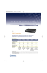
The Digital Business System (DBS) range is a fully hybrid system allowing both digital key telephone and analogue telephone
handsets.
The DBS has a host of features to make it ideally suited to the needs of today’s business user. Some are only available with
certain configurations , others will require the addition of optional equipment or subscription to network services. The list
includes:
ISDN Connection
Remote Programming
Messaging
Call Barring
E&M / AC15A Private Circuits
Music On Hold
DISA
Least Cost Routing
External Paging
On Screen Help (LDS only)
There is a range of three cabinet sizes. DBS38 , DBS68 and DBS90. These can be used individually or combined with a
second DBS90 to give a range of systems DBS38 , DBS68 , DBS90 , DBS128 (DBS90+DBS38) , DBS158 (DBS90+DBS68)
and DBS180 (DBS90+DBS90).
There is also a choice of processors for the DBS, each offering a wide range of features and facilities. Each of the processor
options can be used in any of the cabinet combinations. The feature range is enhanced when using the later CPC cards and
where features are software dependant this is noted in the text. The main feature differences concern networking options and
are outlined below.
The CPC-B v4.2
The CPC-C v1.1 & 1.2
The CPC-EX v1.0
The CPC-EX v2.0
Offers E&M private circuits
Offers ISDN connection via DASSII
Offers E&M and AC15A private circuits and ISDN via DASSII
Offers E&M, AC15A and ISDN via DASSII or Euro-ISDN
The DBS overview section contains important information regarding the system and should also be read before using the
system.
Important
This apparatus must be installed in accordance with BS6701 and general approval NS/G/23/L/100005. This is a condition of
the approval. Any installation which does not comply with this condition will invalidate the approval of that particular
installation.
It is recommended that this system is covered by a maintenance contract issued by a maintainer holding BSI
approval.
When You Need Help
In the event that you require assistance using your DBS system calls should be referred to the vendor of the system or the
system maintainer.
If a fault should develop with the equipment the call must be referred to the system maintainer who will then resolve the
problem. Panasonic do not provide direct technical service and will refer customers to their maintainers for any on site
engineering work required.
Use the space below to record the number of the installer and maintainer.
Installer Name _____________________ Tel: ______________________
Address ____________________________________________________
Maintainer Name ___________________ Tel: ______________________
Address ____________________________________________________
7
Panasonic Digital Business System - Operating Instructions
March 1997
Issue 24
Important Information
This is a class A product.
In a domestic environment this product may cause radio interference, in which case the user may be required to
take appropriate measures.
This product has been CE marked to show compliance with the EMC Directive 89/336/EEC amended by
92./31/EEC and 93/68/EEC.
1
Do not use the telephone system components near sources of electric ‘noise’ or interference. Examples
are: fluorescent lamps, air conditioners, televisions, fridges, washing machines, and radios.
2
The equipment should not be exposed to heat sources, direct sunlight, extreme temperature, moisture or
damp, strong vibrations, greasy or dusty environments.
Operating temperature 0ºC - 40ºC
Operating humidity
0% - 60%
Do not install the equipment in damp or humid environments such as bathrooms and swimming pools.
3
Never attempt to insert wires, pins or similar objects in the vents or openings of the equipment.
4
Never clean the equipment with benzene, paint thinner or other solvent materials. Wipe with a soft cloth to
clean.
5
Do not change the installation location without consulting your dealer/maintainer.
6
Installation of the equipment near welding machines or broadcast antennae may cause interference.
Types Of Extension
There are eleven types of key telephone and two types of operator console which can be connected to the DBS to
meet the various requirements of system users.
The DBS is a hybrid system and allows for the connection of approved two wire analogue extensions. E.g.
Facsimile , Telephone Answering Machines , Cordless and simple telephones. Analogue extensions can originate
and receive calls , but some system features are not available.
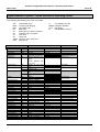
Proprietary Key Telephones
Range To Mid 1996
VB3411
12 Line Key Standard Handset
VB3411DS
12 Line Key Handsfree Display Handset
VB3411LDS
12 Line Key Handsfree Large Display Handset
VB3611D
24 Line Key Display Handset
VB3611DS
24 Line Key Handsfree Display Handset
VB3011
O Line Key Handset
VB3631
Direct Station Selection (DSS) Console
Range From Mid 1996 ( Older handsets can still be used as well )
VBD411
12 Line Key Standard Handset
VBD411DS
12 Line Key Handsfree Display Handset
VBD411LDS
12 Line Key Handsfree Large Display Handset
VBD611D
24 Line Key Display Handset
VBD611DS
24 Line Key Handsfree Display Handset
VB3011
O Line Key Handset
VBD631
Direct Station Selection (DSS) Console
8
Panasonic Digital Business System - Operating Instructions
March 1997
Issue 24
Extension Features
Key Telephone Features
9
Panasonic Digital Business System - Operating Instructions
March 1997
Issue 24
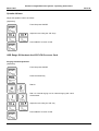
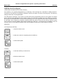
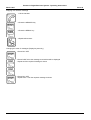
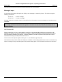
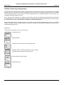
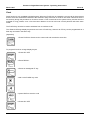
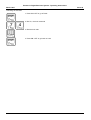
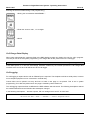
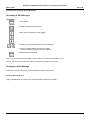
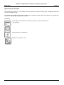
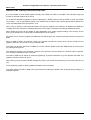
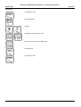
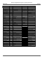
Keys And Their Use
No.
1
2
Item
Speaker
Directory
3
HOLD Key
4
ON/OFF Key
5
6
7
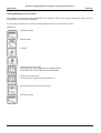
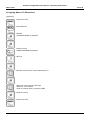
8
9
10
11
12
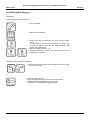
REDIAL key
MEMORY Key
RECALL Key
FLASH Key
CONF Key
MIC Key
VOL Keys
MESSAGE LED
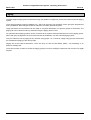
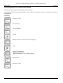
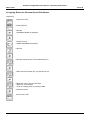
13
14
MIC LED
INT LED
15
16
17
DND/CF LED
FF Key
FF Key LED
18
One Touch
Key
19
Display
No.
20
21
22
23
24
Use / Effect
For ringing , tones and voice
The tray holds an index sheet for the extensions and system speed dial
memories ( not on VB3011 )
Places internal and external calls on hold. Recovers internal and non
appearing line calls from hold.
Switches the keyset on from standby , without having to lift the handset.
The LED in the key will light when the keyset is ON.
Redials the last number dialled
Used to access speed dialling memories
For programming some functions and transferring calls.
Used to end a call but keep the line to make a further call.
For activation of conference function and confirmation of stored data
Turns the built in microphone on or off
For setting incoming ring and speaker volume plus LCD display contrast
Lights when message waiting has been set or system is in power fail
mode.
Lights when internal MIC is on.
Lights when an internal call or non appearing exchange line call is
received or made. It flashes when the call is put on hold.
Lights when Do Not Disturb or Call Forward is set
These can be used as line keys or for certain system features
Lights when the key or feature is active. The LED is two colour Green /
Red.
These keys provide direct access to the extension personal speed dial
memories. They can hold telephone numbers or be used to access
system features.
Shows time and date when the extension is idle. When in use it shows
the number dialled , line used and duration of the call or extension
called. the second line indicates the extension name and number or
system feature in use.
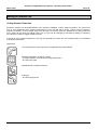
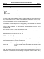
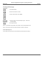
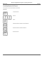
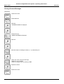
VB3411LDS
These features are only available on the large display key telephone
Item
MENU Key
NEXT Key
PREV Key
One Touch
Key
Large Display
Use / Effect
Returns to main menu display
Displays next screen
Displays previous screen
Used to select the menu item next to the key in the display.
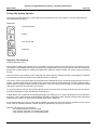
VBD Range
These features are available using the VBD range of keysets released
mid 1996 when used with the CPC-EX card
LINE Key
VOLUME Key
Allows selection of a free line to dial out, using a single key
The volume key is now a single rocking key for up and down adjustment
of ringing and call monitor volumes.
A large easily visible LED is used for message and ringing alerts
The keypad can be used to enter a number to dial before pressing the
LINE key
A call can be relayed via the built in speaker, with one person using the
handset, so others in the office can hear it, though they cannot reply
unless a handsfree telephone is used in handsfree mode.
Using the MUTE key the microphone in the handset can be turned off
temporarily for private consultations with other staff.
Message LED
Live Keypad
Off Hook
Monitor
MUTE Key
7 Lines (1x16,1x15,5x16) LCD display
10
Panasonic Digital Business System - Operating Instructions
March 1997
Issue 24
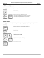
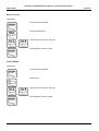
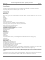
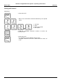
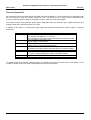
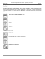
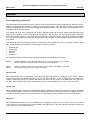
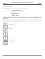
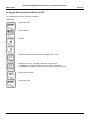
LCD Contrast Adjustment
The display contrast can be adjusted to any one of sixteen different levels.
[Operation]
Press the # key
Press the VOL keys to adjust the contrast.
- The display will darken when VOL down is pressed
- The display will lighten when VOL up is pressed
or
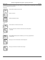
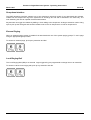
Ringing Volume
The ringing volume can be adjusted using the VOL keys during ringing or by following the sequence below.
[Operation]
When the extension is idle press the ON/OFF key
Press RECALL
Press # 9
- A test ringing tone sounds
Adjust the tone using the VOL keys
or
Press ON/OFF to finish
11
Panasonic Digital Business System - Operating Instructions
March 1997
Issue 24
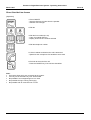
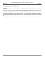
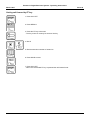
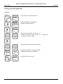
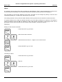
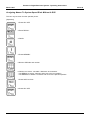
Speaker Volume
Adjust the speaker volume as follows
[Operation]
From idle press ON/OFF
Adjust the tone using the VOL keys
or
Press ON/OFF to return to idle
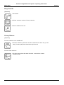
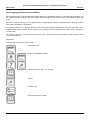
VBD Range Of Handsets And CPC-EX Processor Card
Ringing Volume Adjustment
[Operation]
From idle press ON/OFF
Press the PROG key
Dial #9
Dial 1 for internal ringing or 2 for external ringing and a tone
will be heard.
or
Adjust the tone using the VOL key
or
Press ON/OFF to return to idle
12
Panasonic Digital Business System - Operating Instructions
March 1997
Issue 24
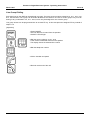
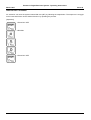
Monitor Volume
[Operation]
From idle press ON/OFF
Press the PROG key
Adjust the tone using the VOL key
or
Press ON/OFF to return to idle
Line Volume
[Operation]
From idle press ON/OFF
Select a line
Adjust the tone using the VOL key
or
Press ON/OFF to return to idle
13
Panasonic Digital Business System - Operating Instructions
March 1997
Issue 24
Fitting The Directory Tray
14
Panasonic Digital Business System - Operating Instructions
March 1997
Issue 24
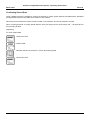
Making An Outside Line Call
Using A Line Key
This method can only be used from a key telephone with line keys. The contents of the display are included for
users of display key telephones.
[Operation]
1 Press a line key that is not lit
- The FF key LED will blink green ( lines used by others will be red).
- The display will show the number of the line selected
- Listen for the outside dial tone
2 Dial the telephone number
- The dialled number is shown in the display
3 Lift the handset and speak when the call is answered
- Handsfree speech is possible if the extension is a handsfree keyset
- The display will show the call duration or charge dependant upon system
programming.
4 Hang up at the end of the call
- If using handsfree press ON/OFF to hang up
- The FF key LED will change from green to red and then go out
- The display will return to time and date display
15
Panasonic Digital Business System - Operating Instructions
March 1997
Issue 24
Direct Outside Line Access
[Operation]
1 Press ON/OFF
- Intercom dial tone is heard from the speaker
- ON/OFF LED will light
2 Dial 88
3 Dial the line number (01-48)
- Listen for outside dial tone
- Display shows the line number selected
4 Dial the telephone number
5 Lift the handset to talk when the call is answered
- Speak into the microphone if a handsfree set is used
6 Re hook at the end of the call
- Press the ON/OFF key if the call was handsfree
Note:
• Only select lines which are connected to the system.
• If a busy line is selected busy tone will be heard.
• Not possible if a non-appearing line is on hold.
• Not possible during incoming call ringing.
• Not possible with an exclusive line on hold
16
Panasonic Digital Business System - Operating Instructions
March 1997
Issue 24
Line Group Dialling
Exchange lines on the DBS can be assigned to groups. There are seven groups accessed by 9 , 811 , 812 , 813 ,
814 , 815 and 816. The 9 group can be further divided into a maximum of 8 sub or ‘tenant’ groups. Any line can
belong to any combination of 9 , 811 - 816 ,but can only be assigned to one 9 tenant group.
Line group access can be programmed into an unused FF key. In this case press the assigned FF key instead of
steps 1 & 2.
[Operation]
1 Press ON/OFF
- Intercom dial tone is heard from the speaker
- ON/OFF LED will light
2 Dial the group number 9 or 811 - 816
- Listen for the outside dial tone from the speaker
- The display shows the selected line number
or
3 Dial the telephone number
4 Lift the handset and speak
5 Re hook at the end of the call
17
Panasonic Digital Business System - Operating Instructions
March 1997
Issue 24
Prime Line Access
By picking up the handset a line is automatically selected ready for dialling.
This function requires programming and specific extension settings to work. It is only available to key telephones.
It allows the immediate seizure of the line or first free line from the group programmed into FF key 1.
The extension which is to use this facility must have Prime Line Access enabled via system programming. The
line or group to be used must be stored under FF key 1 by system programming and another unused FF key
programmed as an Intercom key. This is to allow the extension to select internal dial tone to call extensions and
use other system features.
To set an Intercom key follow the procedure below:
[Operation]
1 Press ON/OFF
2 Press RECALL
3 Press an unassigned FF key
4 Dial #8
5 Press HOLD to store the data
6 Press ON/OFF
With the extension set up in this way when the handset is lifted the outside line is automatically picked up ready
for dialling. To make an internal call or access system features press the Intercom key to get the system’s internal
dial tone first.
18
Panasonic Digital Business System - Operating Instructions
March 1997
Issue 24
ISDN Line
The DBS can be connected to the Integrated Services Digital Network for voice calls. The ISDN channels can be
used in a similar way to the analogue lines. The use of these lines is shown below. See also ISDN Functions On
DBS. The # following the dialled number is required when the en-block dialling method is used. If overlap dialling
is used the # can be omitted. En-block dialling may be required by the ISDN service provider or the facilities used.
[Operation]
1 Press On / OFF or lift the handset
2 Select a channel in the same way as an analogue line: FF Key, 9,
81(1-6), 88(01-48) etc.
3 Dial the telephone number to be called
4 Press # to indicate the number is complete and instruct the system to
send it to the network. This can be omitted when overlap dialling is
used.
Alternatively wait for the dial timer to elapse and the system to send it
automatically
5 After answer speak.
Dialling is the same as for a DBS with analogue lines with the addition of a send character ‘#’ at the end of the
digits to tell the DBS to send a call set up request to the network.
If a send character is not added the system will wait for a pre-set timer to elapse before sending the digits dialled
to the network. The timer is re-started each time a new digit is entered. The send character will prevent delay
waiting for the timer to elapse.
Note:
Pulse dialling analogue SLTs must wait for the timer to elapse to send the digits because the
‘#’ character cannot be sent using pulse dialling.
19
Panasonic Digital Business System - Operating Instructions
March 1997
Issue 24
LINE Key And Live Keypad
( VBD range of handsets with CPC-EX processor )
The LINE key is a specially designated key for selecting a free exchange line, equivalent to dialling On/Off 9.
Therefore for the LINE key to operate the extension must be a member of a dial 9 or tenant group. The LINE key
setting is fixed and is not programmable.
The VBD range of handsets , when used on the CPC-EX can be programmed to have a ‘live’ keypad. This means
that a number can be dialled before the handset is taken off hook and then dialled when the LINE key is pressed.
Each digit must be dialled within 5 seconds of the preceding one or the register will clear and the handset return to
the idle state. If an invalid key is entered the handset clears and returns to idle ( this can also be used as a quick
way to clear an incorrectly dialled number before pressing the LINE key ). Live keypad is not available on the old
CPC-B or CPC-C or the VB3xxx handsets. Dial 9 access (MC0) must be set up for this feature to operate.
[Operation]
Live Keypad And LINE Key
1 Dial the number to call
2 When the number is complete press the LINE Key
3 After answer speak.
LINE Key
1 Press the LINE key to select a line
2 Dial the number to call
3 After answer speak.
20
Panasonic Digital Business System - Operating Instructions
March 1997
Issue 24
Making An Internal Call
Calling Another Extension
Extension numbers can be dialled directly to the system to establish a call to another extension. The call can be
tone or voice depending upon system programming. A tone call will emit a series ‘peep’s from the receiving
extension’s speaker. A voice call will ‘peep’ once and then connect the extension speaker to the calling extension
so the caller can be heard. the calling mode, tone or voice can be changed by the caller by dialling a 1 following
the extension number to toggle between the two.
If the call is to an analogue telephone it will ring, the equivalent of a tone call. Voice calling mode is not available
to analogue extensions.
[Operation]
1 Lift the handset or if the extension is a speakerphone press ON/OFF
2 Dial the destination extension number
- To switch between voice and tone calling modes dial 1
- The INT LED Lights
3 Speak after the recipient answers
4 Hang up
- The INT LED goes out
21
Panasonic Digital Business System - Operating Instructions
March 1997
Issue 24
Calling The System Operator
The system operator extension is connected to the first extension port on the system. It can be called from any
other extension by dialling 0.
[Operation]
1 Lift the handset
2 Dial 0
3 On answer talk
4 Hang up
Operator Call Queuing
(CPC-EX processor only )
Internal callers dialling the operator using 0 will always receive ringing tone and will queue if the operator is busy.
This facility is now standard and does not require any programming of the system. Internal calls from extensions,
private wire or DISA will queue. Dialling the operator by extension number instead of 0 will not invoke the queuing
function.
There is no limit to the number of such calls that can queue. Queuing internal calls will not be subject to Operator
Call Overflow and will not transfer if the overflow facility is configured.
The order in which the queued calls are answered will be determined by the Incoming Ringing Priority set for the
system. If external calls are given highest priority the internal calls will queue behind any incoming external calls; if
internal calls are highest priority they will be queued in front of incoming external calls. In both cases the internal
calls will be queued in the order they are received.
If a second operator is set up, the internal calls will queue for both and ring through to the first one to become free.
If Off Hook Signalling is set a call waiting tone will be sent.
In Night Mode, dial 0 will queue to the designated night ring telephone. If no night ring telephone is set it will return
busy tone. If the system mode changes between Day/Night or Night/Day whilst calls are queuing those calls will be
unaffected and continue to queue until answered at the current extension.
If 0 is stored under an FF key, the key will not operate as a BLF and cannot be used for operator pick up. Use an
FF key with the operator extension number stored for operator BLF and pick up functions.
Operator call queuing will not operate if:
The operator extension is disconnected
If the operator extension is in programming mode
If the operator extension is in name setting mode
22
Panasonic Digital Business System - Operating Instructions
March 1997
Issue 24
Receiving Calls
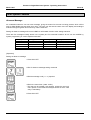
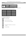
Incoming Call Ring Priority
( CPC-EX processor )
The priority of incoming calls can be determined via programming. Either internal calls or external calls can be
given highest priority and will override lower priority calls which may be ringing at an extension when they are
received.
If 2 calls of the same priority level are ringing they are answered on a first come first served basis, except DDI and
DISA calls which will not camp on.
External Priority
High
Operator
Call Back
External
Internal Priority
Low
Internal
DDI
DISA
Recall
Transfer
Group calls
High
Low
Alarm Paging Internal Operator
DDI
Call Back
DISA
External
Recall
Transfer
Group calls
Alarm
Paging
Intercom Calls
When a tone call is received or on an analogue telephone a single ring is heard, lift the handset to answer the call.
If the extension is a digital handset with a display the name of the calling extension will appear in the display.
[Operation]
1 Lift the handset
- On a key set the INT LED lights
23
Panasonic Digital Business System - Operating Instructions
March 1997
Issue 24
Outside Line Calls
Auto Answer
When an extension set to auto answer rings the call can be answered simply lifting the handset. If there are
several lines ringing the extension the longest ringing call is answered. This facility will also answer hold recall and
transferred call ringing. Auto answer is set via system programming.
[Operation]
1 When the telephone rings lift the handset to answer.
Auto Answer Not Set / Extension Not Ringing
To answer a ringing call on an extension which is not set to auto answer or to answer a call from an extension
which is not ringing.
[Operation]
1 Lift the handset
2 Press the line key which is slowly blinking red to answer the call
- A rapid red flashing LED indicates a call on hold at another extension
24
Panasonic Digital Business System - Operating Instructions
March 1997
Issue 24
Call Pick Up
The DBS supports call pick up operations. Using these features calls ringing at other extensions can be picked up
from extensions which were not ringing. There are two forms of call pick up , Group and Directed. Pick ups will not
answer alarm calls or call back ringing.
Group Pick Up
Group pick up requires that the extensions be allocated into groups and the system told which type of groups to
use for pick up via system programming. Group pick up can be set to operate on any one of the following group
types, Hunt Groups , Paging Groups or Pick Up Groups. The decision as to which type to use is made at the time
the system is installed. Changes to the type of group used or the members of any group require engineer
reprogramming and cannot be performed by the user.
If several calls are ringing to a group the lowest calling extension number or longest ringing line is answered first.
An extension can only belong to one hunt group and one pick up group but can be a member of several paging
groups.
If pick up is via paging groups and an extension using this feature belongs to more than one paging group the
system searches upwards from the lowest numbered paging group until it finds a call to answer or has searched all
the groups.
The group pick up command can be programmed under an FF or One Touch key.
[Operation]
1 Lift the handset
2 Dial the pick up code 70
3 Speak to the caller
4 Hang up
25
Panasonic Digital Business System - Operating Instructions
March 1997
Issue 24
Directed Call Pick Up
Directed pick up allows and extension to answer a call ringing at a known extension number.
If several calls are ringing to the target extension the lowest calling extension number or longest ringing line is
answered first.
[Operation]
1 Lift handset
2 Dial 7*
3 Dial the extension number of the extension to be answered
4 Speak to the caller
5 Hang up
Handsfree Answerback
This function is only available to digital extensions which have a MIC button. It allows the extension user to
respond to voice calls without needing to lift the handset. To use this facility ensure that the MIC light on the key
set is on. If it is not press the MIC button to light it. When a voice call is received the microphone in the base of
the telephone will be activated and will allow handsfree spoken reply. Keep within three feet of the microphone
and speak clearly for best effect.
26
Panasonic Digital Business System - Operating Instructions
March 1997
Issue 24
Group Ringing
The DBS can support upto 50 ringing groups of 8 members each, for ISDN DDI or analogue incoming lines.
Group ringing will operate for the following types of incoming call:
Internal Incoming
Transferred Calls
DISA Incoming
E&M Incoming
When calling a group from another extension the following features are barred and will return error tone to the
caller:
Message
Call Waiting
Call Back
Override
Off Hook Voice Announce
Voice Calling ( All calls to groups are forced into tone call mode)
Group ringing function will not operate in the following circumstances:
Direct incoming call to a member extension
Call Forward to a group cannot be set
Hunt Groups cannot include ringing groups as members
Hold Recall to a member extension
ISDN DDI to a member extension
Operator Reversion
Paging Call
Delayed Ringing
Prime Line
Transfer Recall
DDI Reversion
Call Back
Alarm ringing
If a member extension sets any of the following features it will be removed from the ringing group:
Call Forward
Absence Message
Do Not Disturb
Ringing for another call
Off hook, monitor or handsfree in use
Non appearing exchange line on hold
SLT ring generator overload, if the extension is an SLT
During programming of system or memories
No extension number assigned to the port
When a call is passed to a group ringing is presented and all idle extensions in the group ring. If an extension that
was busy when the call arrived becomes idle before the call is answered it will not begin to ring.
Calls can be transferred to a group from another extension, as soon as ringing is heard by hanging up. The group
is searched for free extensions when the extension calls the group and again when the call is transferred before
answer.
If the group is busy and a forced transfer is performed the group will be continually searched until an extension
becomes free or the reversion timer has elapsed. Multiple calls can be transferred to a busy group.
27
Panasonic Digital Business System - Operating Instructions
March 1997
Issue 24
If the call is not answered before the recall or reversion timers have elapsed then the call will recall to the
transferring extension.
Group numbers cannot be assigned for use in hunt groups and manager secretary groups.
If the group number is matched to an extension, the extension cannot be the destination of a Call Forward. If the
matched extension sets a Call Forward the group ringing function will be disabled.
Off hook signalling does not operate for group ringing calls.
If the group number is assigned to an FF key or DSS key, at another extension, it will not light when the group is
called and the call cannot be picked up using the key.
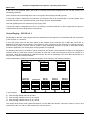
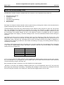
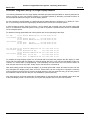
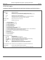
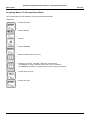
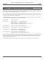
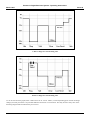
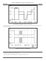
Group Ringing - CPC-EX v2.1
Membership of the DDI / Ring Groups has been extended from the original 8 to 32 members with the introduction
of the CPC-EX v2.1 software.
A new Hunt Group type has also been added to the software for the exclusive use of DDI calls. There are an
additional 16 DDI Hunt Groups allowing 16 members of each. Members can be extensions or DDI Ring Groups,
and the hunting mode is circular, with no answer or busy searching. No follow on group or alternative hunting
modes are supported. The existing Hunt Group operation is unchanged
For DDI Ring Groups to be included in a Hunt Group they will require a virtual extension number to be assigned to
reference them by. Extensions cannot be members of more than 1 DDI Hunt Group and cannot be included in a
more than 1 Ring Group assigned to a DDI Hunt Group, but can be individually in the same DDI Hunt Group as a
Ring Group in which it is also a member.
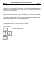
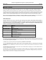
Group membership conditions for normal Hunt Groups are unchanged. (see following example )
In this example:
a)
b)
c)
d)
Cannot assign EXTN 300 to B, D and E
Cannot assign GROUP 310 to A, B, D and E
Cannot assign GROUP 320 to A, B, C and E
Cannot assign GROUP 330 to A, B, C and D
The original Hunt Group hunting takes precedence over the DDI Hunt Groups. If there are calls to A and C and
300 becomes idle, the call on A will have priority over the call to C.
28
Panasonic Digital Business System - Operating Instructions
March 1997
Issue 24
Holding Calls
The hold function allows the extension user to temporarily suspend a call. The other party will hear comfort tone (
a ‘peep - peep’ every 5 seconds) or music on hold if installed. The extension user can then return to the call or
transfer it to another extension.
There are five types of hold on the DBS.
•
•
•
•
•
System Hold
Exclusive Hold
Brokers Hold
Extension Park Hold
Operator Park Hold
Analogue extensions cannot select system or exclusive hold modes. This is determined by system programming.
Analogue extensions place a call on hold by pressing the RECALL key.
If Automatic Exchange Line Hold is set via programming, when talking to an outside call , pressing another line
key will place the first call on system hold and immediately present dial tone for a second call. This means that
any other extension can retrieve the held call.
Non appearing exchange lines are held and retrieved by pressing the HOLD key. The type of hold is the same as
for analogue extensions which is determined via system programming.
A call which has been left on hold will recall to the holding extension after a time determined by system
programming. If the holding extension does not answer the call the call will revert to the operator extension unless
the line used is assigned as a private line to the holding extension, when call reversion does not operate.
System Hold
System hold places the call on hold such that any extension can retrieve it. Other keysets will see a quickly
flashing red LED for the held line, and can retrieve the call by pressing the line key or dialling the direct line
access code 88 followed by the line number.
[Operation]
To place a call on system hold
1 Press HOLD to place the call on system hold.
- The line key LED will rapidly flash red.
To retrieve a call from system hold
1 Press the line key with held call.
- The LED will be rapidly flashing red.
29
Panasonic Digital Business System - Operating Instructions
March 1997
Issue 24
Exclusive Hold
Exclusive hold will place the call on hold , but will only allow the extension which placed the call on hold to recover
it.
[Operation]
1 Press the line key the call is presented on to hold and retrieve the call
- When putting the call on hold the key will flash green quickly and internal
dial tone will be heard
- When retrieving the call the key will stop flashing and remain lit.
Intercom Hold
Internal calls from other extensions can be held by pressing the HOLD key to hold and retrieve a call. Conference
call , voice call , doorphone call and paging calls cannot be held.
[Operation]
To hold an intercom call
1 Press HOLD
- INT LED flashes
- The held party will hear comfort tone of music on hold as configured.
To retrieve a held intercom call
1 Press HOLD
- INT LED stays lit
30
Panasonic Digital Business System - Operating Instructions
March 1997
Issue 24
Brokers Hold
Most commonly used for analogue extensions this feature will also work with key sets using non appearing
exchange lines. System programming feature Call Brokering must be set to retrieve the held exchange line for this
to operate.
An extension on a non appearing exchange line call can hold the call using the HOLD key and make an internal
call. It can then shuttle between the two using the HOLD key. Calls can be ended by hanging up without pressing
HOLD, then returning to the second call and continuing as a normal call.
[Operation]
1 Press HOLD when talking to a non appearing exchange line
2 Dial the internal extension and wait for answer
3 Press HOLD to return to the original call
- Further presses will shuttle between the calls
31
Panasonic Digital Business System - Operating Instructions
March 1997
Issue 24
Extension Park Hold
Park hold is used to hold a call , whose recipient’s location is not known. Park hold differs from other forms of hold
in that it can be retrieved by any extension who knows the extension number where the call was parked. The line
number does not need to be known , nor does the retrieving extension need a line key for the call. After placing
the call on park hold page the recipient and announce the parked call and extension number it is parked on , they
can then retrieve it at any extension.
If the call is not retrieved it will ring back after the time set in system programming.
An extension can only have one parked call at one time.
[Operation]
To park a call at an extension.
1 Press HOLD
2 Dial 82
To retrieve a parked call
1 Lift handset
2 Dial 83 park hold release
3 Dial the extension number where the call is parked
32
Panasonic Digital Business System - Operating Instructions
March 1997
Issue 24
Operator Park Hold
In a similar way to extension park hold the operator can park calls for retrieval by other extension users. The
differences are that the operator has 10 park positions (0 to 9) which are shared between the two operator
positions if a second operator is installed.
The park hold positions are allocated to the second row down on the operators DSS console by default settings
and are accessible to the operator directly by pressing the DSS FF keys.
[Operation]
For the operator to place a call on park hold
1 From the operator press HOLD
2 Dial 82 followed by the park location 0 - 9
or
2 Or press the DSS key for the park location
For an extension to retrieve the call
1 Lift the handset
2 Dial 84 operator park hold retrieve
3 Dial the park hold location 0 - 9
33
Panasonic Digital Business System - Operating Instructions
March 1997
Issue 24
Call Transfer
The DBS has two modes of call transfer which can be used to pass calls to other extensions within the system.
These are supervised and unsupervised transfer.
Supervised transfer involves calling the destination extension and waiting for the extension user to answer and
announcing the call prior to transferring it.
Unsupervised transfer sends the call to the extension regardless of whether the recipient answers or not.
The ability of an extension to transfer calls and the type of transfer that can be used are specified via system
programming.
A transferred call which is not answered within a specified time will revert to the transferring extension.
Supervised Transfer
[Operation]
1 Press HOLD to place the call on hold.
2 Dial the destination extension number
3 Announce the call when the destination extension answers
4 Hang up to transfer the call
34
Panasonic Digital Business System - Operating Instructions
March 1997
Issue 24
Unsupervised Transfer
[Operation]
1 Press HOLD to place the call on hold.
2 Dial the destination extension number.
3 Hang up to transfer the call without waiting for an answer.
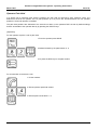
Special Keys
During the process of transferring the following keys have special actions.
If the transferring extension presses RECALL it will force the transfer of the
call on hold to the called extension without the need to replace the calling
extensions handset.
If the called extension presses the HOLD key it will seize the held call from
the calling extension , terminate the call from the other extension and be
connected directly to the previously held caller.
If the transferring extension presses the CONF key when talking to
destination extension a conference call is created with both extension
called party all able to speak to each other. The transferring extension
then drop out , by hanging up and leave the destination extension
previously held caller talking to each other.
the
and
can
and
Trunk To Trunk Transfer & Conference
( CPC-EX processor )
A call on hold at an extension can be transferred to an external number by the extension. With the call on hold a
line is selected and the new number dialled, the call can then be transferred by going back on hook, pressing an
FF Key assigned as a TRANSFER key ( store *6 under the key ) on the VB3xxx range of handsets or PROG on
the VBDxxxx range of handsets, pressing an FF key programmed as a RELEASE key or RELEASE on the DSS,
an FF key programmed as a TRANSFER key (*6) or using the new large display menu option.
If the DBS is linked using a networking card an extension on system A can transfer calls to and between line
system B by a similar method using on hook or RELEASE key transfer.
Calls can also be transferred between lines by dropping out of a conference using the methods described above.
A conference call can be initiated by holding a call, setting up a new call and then pressing the CONF key. When a
call is conferenced in this way DTMF transmission to the lines during the call is disabled. If the extension making
the call places the calls on hold both external parties are placed on hold and held separate form each other.
35
Panasonic Digital Business System - Operating Instructions
March 1997
Issue 24
Programming is required to enable trunk to trunk functions. The options below for transferring the call will depend
upon the programming of the system.
[Operation]
1 Press HOLD to place the call on hold.
2 Select a new line
3 Dial the destination number.
Then
1 Press CONF to conference the two calls
2 Hang up to leave the conference and leave the two other parties
connected.
Or
1 On the VBD handsets press the PROG key or an FF key programmed as
a transfer key
2 Hang up to connect calls without conferenceing them
Or
1 Hang up to transfer the call without annoucing it.
36
Panasonic Digital Business System - Operating Instructions
March 1997
Issue 24
Termination Of Trunk To Trunk Calls
Trunk to trunk termination is initiated by either clear signal detection (CPC/DCT/CDT), timer or operator
intervention.
If clearing by clear signal detection is selected the timer option is disabled. The DBS will, however, clear any trunk
to trunk call after 4 hours. Before clearing the call it will give a 3 beep warning 1 minute before and 5 beeps at 10
seconds before cutting off the call.
The operator can cut off calls if on hook transfer is disabled. To do this the operator selects a busy line, breaks in
by dialling 4,places the calls on hold with the HOLD key then selects each line in turn an clears it down by hanging
up.
The call logging record produced after a transfer will allocate the call to the extension which transferred the call.
37
Panasonic Digital Business System - Operating Instructions
March 1997
Issue 24
Conference Calls
A conference call is call involving more than two parties. The DBS provides four methods of conferencing calls.
These are:
•
•
•
•
•
External Conference
Internal Conference
Trunk To Trunk Conference
Busy Override
Privacy Release
An external conference is a call involving two system extensions and an outside line call.
An internal conference is a call involving three system extensions.
Trunk To Trunk Conference is a conference call involving two exchange lines and one internal caller. All parties
are cut off if the internal caller drops out of the conference. (See the previous section for the operation of trunk to
trunk transfer and conference )
Busy Override requires system programming . Using it allows an extension to break into the call of another
extension and force a conference call. The extensions must be in the same paging group other than group 0 and
have been given the ability to make and receive break in. This programming must be performed by a qualified
engineer. Busy override will not break into an existing conference call nor will it work if the originating extension is
already in a conference.
Privacy Release is an alternative method of creating an external conference by allowing another extension to pick
up the same line and join in the call.
An internal party to a conference call can drop out by hanging up or pressing the FLASH key.
The DBS can support eight conference calls simultaneously and optionally via programming provide a conference
splash tone to indicate a conference call is in progress.
SLTs and VB3011 Constraints When Conferencing
These are single line devices and as such cannot deal with calls involving more than one external line or channel.
Whilst a two extension to single line call is possible, one extension to two lines or channels cannot be invoked by
or for an SLT or VB3011 extension.
38
Panasonic Digital Business System - Operating Instructions
March 1997
Issue 24
External Conference
[Operation]
1 During an internal call press HOLD to hold the call
2 Select an outside line
3 Dial the telephone number of the third party
4 After answer inform the called party that you are creating a conference
call and press CONF. All three parties can now talk to each other.
Internal Conference
[Operation]
1 During an internal call press HOLD to hold the call
2 Dial the extension number of the third party
3 After answer inform the called party that you are creating a conference
call and press CONF. All three parties can now talk to each other.
39
Panasonic Digital Business System - Operating Instructions
March 1997
Issue 24
Busy Override
[Operation]
1 Lift handset
2 Dial the extension number of a busy extension
3 Dial 4 to break into the call.
Privacy Release
[Operation]
From the extension on an outside call.
1 Press the CONF key and inform the other extension user which line you are
using. The other party has 15 seconds to join the call.
From the other extension
1 The other party selects the same line within 15 seconds to create a
conference call.
40
Panasonic Digital Business System - Operating Instructions
March 1997
Issue 24
When You Receive Busy Tone
The DBS has a number of options available when the extension or line requested is busy these are:
•
•
•
•
•
•
Exchange Line Camp On
Call Back Message
Call Waiting
Call Waiting With Message
Voice Announce
Busy Override
Exchange Line Camp On allows extension users to queue for busy exchange lines. When a line becomes free the
system will call back to the extension and connect he line to it.
Call Back Message sets a flag at the called extension which allows the busy extension to return the call at a later
time. Four messages can be queued to an extension at one time. If the extension is called a second time and
connected the feature is cancelled. If call forward is set the message is set on the destination extension to which
the call forward is set. Display keysets can see on the display the number of messages set and can rotate the
order of messages when replying. A call back message can be set at an unattended extension without calling the
extension.
Call Waiting will send a tone to the busy extension which can then respond by holding the call they are on and
taking the call or continue the call and not accept the waiting call. Call waiting and voice announce can be
answered by using a ‘talk-back’ key. Call Waiting will not work if the target extension has set DND, is engaged in a
conference call, is receiving an alert tone from another call waiting or is ringing. If the calling extension hangs up
call waiting is cancelled.
Call Waiting With Message allows the call waiting tone to be sent together with a text message which will appear
in the screen of a digital display handset. Otherwise it operates in the same way as Call Waiting. The messages
initially stored in the system are:
Message Code
5
6
7
8
9
Message
VISITOR HERE
NEED HELP
IMPORTANT
URGENT
EMERGENCY
Voice Announce allows the calling extension user to speak to the called extension without the other party hearing.
E.g. If an extension is on an outside line call the outside caller will not hear the announcement. Voice Announce
can be answered by using the ‘talk-back’ key.
Busy Override will create a conference call, with all parties connected together.
‘Talk-back’ is a function only available to digital keysets which can be programmed under an FF key which will
allow single key answering of call waiting , call waiting with message or voice announce by holding the first call
and connecting the extension to the waiting call. Further presses toggle between the two calls.
41
Panasonic Digital Business System - Operating Instructions
March 1997
Issue 24
Exchange Line Camp On
[Operation]
Setting
1 Press ON / OFF
2 Press the busy line key
- Busy tone is heard
3 Dial 6 to camp on
4 Press ON / OFF
When the ring back tone is heard
1 Lift the handset , listen for dial tone and dial
- The ringback must be answered within 15 seconds or the feature is
cancelled.
- If the setting extension is busy on another call the ringback will wait for the
extension to become free before ringing back.
- If the extension is busy for more than 20 minutes the ringback feature is
automatically cancelled.
To cancel a camp on request
1 Press ON / OFF
2 Dial 76 call back cancel
3 Press ON / OFF
42
Panasonic Digital Business System - Operating Instructions
March 1997
Issue 24
Call Back Message
[Operation]
Setting a call back message - by calling the extension.
1 Press ON / OFF
2 Dial the extension number
3 When busy tone is heard dial 2
4 Press ON / OFF
Setting a call back message - without calling the extension
1 Press ON / OFF
2 Dial 75
3 Dial the extension number where the message is to be set
4 Dial * to set the message
5 Press ON / OFF
43
Panasonic Digital Business System - Operating Instructions
March 1997
Issue 24
Replying to a call back message
1 Lift the handset
2 Press the MEMORY key
3 Press the REDIAL key
4 Speak after answer
Changing the order of messages (Display keysets only)
1 Press ON / OFF
2 Press CONF twice the message received last will be displayed
- Repeat until the required message is shown
3 Press ON / OFF
- Repeat from 1 until the required message is shown
44
Panasonic Digital Business System - Operating Instructions
March 1997
Issue 24
Cancelling a call back form the called extension
1 Press ON / OFF
2 Press MEMORY
3 Press FLASH
4 Press ON / OFF
Cancelling a call back message from the setting extension
1 Press ON / OFF
2 Dial 75
3 Dial the extension number where the message is set
4 Dial # to set the message
5 Press ON / OFF
45
Panasonic Digital Business System - Operating Instructions
March 1997
Issue 24
Call Waiting
[Operation]
Setting call waiting
1 Lift the handset
2 Dial the busy extension
3 When busy tone is heard dial 3 to send the call waiting signal
- If the extension will accept call waiting the busy tone changes to ringing
tone and the other extension will receive call waiting tone
Answering call waiting
1 Disconnect the first call and lift the handset to be connected
to the second caller
or
2 Press the ‘talk-back’ key
- The first call is held and the second call is connected
- Further presses toggle between the two calls
- ‘Talk-back’ is only available to digital keysets
46
Panasonic Digital Business System - Operating Instructions
March 1997
Issue 24
Call Waiting With Message
[Operation]
Setting call waiting with message
1 Lift the handset
2 Dial the busy extension
3 When busy tone is heard dial 3 to send the call waiting
signal
- If the extension will accept call waiting the busy tone
changes to ringing tone and the other extension will
receive call waiting tone
4 Dial the message code (5 - 9)
- Analogue extensions cannot sent code 8 since this is
reserved for ‘Transfer’
Answering call waiting with message
1 Disconnect the first call and lift the handset to be connected
to the second caller
or
2 Press the ‘talk-back’ key
- The first call is held and the second call is connected
- Further presses toggle between the two calls
- ‘Talk-back’ is only available to digital keysets
47
Panasonic Digital Business System - Operating Instructions
March 1997
Issue 24
Voice Announce
[Operation]
Originating voice announce
1 Lift the handset
2 Dial the busy extension
3 When busy tone is heard dial 5 to make the announcement
- After making the announcement either wait for an answer or hang up
Answering voice announce
1 Press the ‘talk-back’ key
- The first call is held and the second call is connected
- Further presses toggle between the two calls
- ‘Talk-back’ is only available to digital keysets
Busy Override
[Operation]
1 Lift handset
2 Dial the extension number of a busy extension
3 Dial 4 to break into the call.
- The same restrictions as busy override in the conference call section apply.
48
Panasonic Digital Business System - Operating Instructions
March 1997
Issue 24
Paging
The DBS supports paging announcements through the speakers of digital key sets and an optional external paging
system.
There are eight paging groups numbered 0 to 7 which can be used. The members of each group are programmed
during installation, later changes should be referred to a suitably qualified engineer.
Using this feature announcements can be made on a system wide basis or to specific groups of extensions. The
paging call can be answered at any extension using the paging answer code.
An optional external paging system can be connected to the system and associated with one of the paging groups.
When that group is paged the announcement will also be broadcast over the external paging system.
Only one extension can be paging at any one time using groups 1 to 7, however a page using group 0 will override
the simultaneous paging of the other groups.
Paging will not be heard at extensions which are busy or have Do Not Disturb (DND) , call forwarding or an
absence message set.
There are two sets of codes to access the paging groups one set for analogue extensions and the other for digital
keysets.
49
Panasonic Digital Business System - Operating Instructions
March 1997
Issue 24
[Operation]
Making a paging call
Analogue
Digital Keysets
1 Lift handset
2 Dial the paging code
- 6 for analogue extensions
- #0 for digital keysets
3 Dial the paging group number ( 0 - 7 )
4 Make the announcement
5 Wait for an answer or hang up
50
Panasonic Digital Business System - Operating Instructions
March 1997
Issue 24
Answering a paging call
Analogue
Digital Keyset
1 Lift the handset
2 Dial the page pick up code
- 69 for analogue extensions
- ## for digital keysets
3 Speak to the paging party
Setting and cancelling page do not disturb ( Digital keysets only)
1 Press ON / OFF
2 Dial 7#
- The same sequence is used to set and cancel Page DND
3 Press ON / OFF
51
Panasonic Digital Business System - Operating Instructions
March 1997
Issue 24
Call Forwarding
The DBS allows calls to forwarded in the event an extension cannot or does not want to accept calls. The latest
system software allows for four call forwarding conditions to be specified. These are:
•
•
•
•
•
•
All Calls
Busy
Busy / No Answer
No Answer
Follow Me
Call Forward To Outside Line
(Software v4.0 onwards)
( CPC-EX processor )
Call Forward All Calls will send all calls to the extension to the designated alternative extension. This option can
also be stored under an unused FF key in software v4.0 and higher so that the forward setting is single key press.
Call Forward Busy will only forward calls the designated extension if the first extension is already busy. If the first
extension is not busy when the call arrives it will ring and not be forwarded.
Call Forward Busy / No Answer will forward calls if the extension is busy or does not answer after a pre-determined
period of time. The no answer time is specified via system programming.
Call Forward No Answer will only forward calls if the extension does not answer. If the extension is busy another
incoming call will not be forwarded. This option is especially useful when forwarding to voicemail systems
connected to the DBS.
Call Forward Follow Me allows call forward all calls to be set at an extension from a separate extension. This
feature allows user to remotely re-direct their calls to their current location.
An extension which is the target of a call forward from the operator extension cannot set call forward. Calls cannot
be forwarded to extensions which have themselves set call forward.
All call forward settings are cancelled by the same code - 72.
Call Forward For Voice Systems
Version 4.0 and later software provides facilities for use when a voice processing system is attached to the DBS.
These systems are attached via analogue card supported ports.
Voice systems on the DBS can be configured in one of three ways:
Automated Attendant (AA)
Calls ring into the voice system which then handles them in a similar way to a
central operator eventually transferring them to a required extension.
Voicemail (VM)
Calls received are routed to a specified user mailbox where the caller can leave
a message.
Combined AA/VM
Has ports configured to do both of the AA and VM functions on a single system.
In the system programming a specialised analogue port type can be set up for use with a voicemail or similar
system. This will give the port special privileges and restrictions relevant to voicemail connection. The majority of
these are hidden in the workings of the system and not ‘visible’ to the users. They are concerned with call camp on
and restriction of such features as DND and call forwarding. The change most relevant to the users is the ability
for VM ports to receive the mailbox ID from extensions forwarded to them
52
Panasonic Digital Business System - Operating Instructions
March 1997
Issue 24
The following commands are used to provide interaction with voice systems.
Message Lamps
A connected voice system will require the facility to set messages on extension phones. This is done using the
following commands:
75 Ext. No. *
75 Ext. No. #
To set a message
To clear a message
Message setting and cancelling must be controlled by the voice system to ensure messages are correctly set and
cancelled.
Note: The message lamp must be set and cancelled from the same voice system port. It is recommended
that a single port on the connected voice system is allocated for this task, otherwise the lamps will not
operate correctly.
Call Forward ID
System extensions can have a call forward ID set which will be automatically dialled when that extension call
forwards to a VM port. Key sets can set their own, VB3011, VB3411 and analogue ‘phones need the ID to be set
from the operator extension (see page 99 - Operator Features). This ID is only sent to VM ports when a call is
forwarded forwarding non VM ports will not receive it.
The ID code can be upto 20 digits consisting of 0 - 9,*,# or Redial (to give a pause)
Call forward is used to divert calls to the VM ports. In addition to the existing options there is also a no answer only
option, and single FF key command option and operator setting option. The call forward command now becomes:
53
Panasonic Digital Business System - Operating Instructions
March 1997
Issue 24
Setting Call Forward Identification
This sets the DTMF sequence to be automatically dialled when forwarding to a voicemail port. It will not be sent if
the extension forwards to any other type of port or extension.
[Operation]
1 Press ON / OFF
2 Press Recall
3 Press MEMORY
4 Dial *
5 Enter the ID to be used. Upto 20 Characters, see description text.
6 Press HOLD
7 Press ON / OFF
Suppression Of Call Forward Indication On LCD and BLF
With the introduction of version 4.1 and ISDN 1.1 software it is possible to suppress the display of call forward
indication from the second line of a keyset LCD and green LED indication on BLF keys, when an extension sets
call forward.
This is useful when many users will be setting forward to voicemail and do not want these indications present.
When suppressed the DND/CF LED on keysets will still be illuminated to indicate call forward status.
This requires system programming by a qualified engineer.
54
Panasonic Digital Business System - Operating Instructions
March 1997
Issue 24
Setting call forward
[Operation]
1 Press ON / OFF
2 Dial 72 the call forward command followed by the required
option
,
,
1 - All Calls
2 - Busy
3 - Busy / No Answer
5 - No Answer
or
3 Dial the destination extension number to receive the
forwarded calls
4 Press ON / OFF
- On a digital key set the DND/CF lamp will light
- Analogue extensions will hear a broken dial tone when off
hook
55
Panasonic Digital Business System - Operating Instructions
March 1997
Issue 24
Setting call forward by FF key
1 Press ON / OFF
2 Press RECALL
3 Press the FF key to be used
- The key must not currently be set as a line key
4 Dial *5
5 Dial the extension number to forward to
6 Press HOLD to store
7 Press ON / OFF
- When the call forward FF key is pressed the call forward is set
56
Panasonic Digital Business System - Operating Instructions
March 1997
Issue 24
Setting call forward follow me
1 Press ON / OFF
2 Dial 77 the follow me setting command
3 Dial the extension number to forward calls from
4 Dial the extension number to forward calls to
5 Press ON / OFF
Call Forward To An Outside Line
Call forward to an external number can be set by any extension ( except the operator ) which is not restricted via
programming from doing so.
The number to which calls are to be forwarded must be stored in the extension’s own Personal Speed Dials or the
System Speed Dials before setting up the forward function. ( please refer to the Operating Manual for details
regarding storage of speed dial locations )
The speed dial location used must include line access using the CONF (0-6) option, where 0-6 are the line groups
set up in the system programming.
If an SLT or VB3011 handset is to be used then the line access group must be specified using the following
sequence ( please refer to Storing Personal Speed Dials for more information )
8 * (90-99) * (0-6) Telephone Number Recall
PSD No. Line Group
Once the speed dial location has been stored, Call Forward To An External Number can be set by:
On/Off 7 2 4 nn On/Off
nn=00-89,100-189 200-289 or 90-99
Where nn is the PSD or SSD location which holds the destination number. To cancel:
On/Off 7 2 On/Off
57
Panasonic Digital Business System - Operating Instructions
March 1997
Issue 24
This feature will not operate if the extension is receiving a call, has a call on hold, has not stored the selected
memory location correctly or is barred from setting the feature by programming. It will cancel DND, Absence
Messages, Follow Me settings and any other call forwards which have been set. It will be cancelled if any of these
features is set after it.
Should the speed dial location be cleared or altered whilst being used to direct a call forward the extension or
extensions using it will revert to DND mode, cancelling call forward.
When an external call forward is set the extension is removed from hunt groups, coverage groups, ring groups and
DDI groups. When set the extension cannot be used to make of receive calls until the forward is cancelled.
Multiple calls can be redirected by external call forward from a single extension. However be sure there is
sufficient capacity at the destination number to handle many calls if multiple calls are to forwarded or the callers
will get busy tone.
The operator extension cannot set a call forward to an external number, even if internal call forward has been
enabled.
The types of call which will follow an external call forward, when allowed by programming are:
Internal tone and voice calls
Calls from the private wire (DC5) if breakout is set
Transferred calls
ISDN Personal DDI calls
The following call types will ignore an external call forward and not get transferred to the external destination:
Incoming ringing calls ( calls must be answered first and then transferred by another user )
All forms of Group call
Paging calls
Alarm calls
Delayed ringing calls
Private line calls
Call back calls
Call forward from another extension
Recall
All types of call reversion
When call forward to external is set the extension’s status is indicated in several ways. The DND/CF LED is lit,
DSS keys for the extension will show green, SLTs and VB3011 will have a broken dial tone when taken off hook,
display keysets will show FWD NNNN ( where NNNN is the memory used to forward ) on the second line of the
display.
When a call is forwarded the extension is making an external call. Call barring, tenant groups, LCR and call
logging functions will all operate as normal, barring the call if the number is restricted to that extension. The call
logging output will show, in addition to the line and time of the call, an F condition code and an E on the end of the
extension number followed by the forwarding telephone number E.g.:
F
200E01234567890
58
Panasonic Digital Business System - Operating Instructions
March 1997
Issue 24
[Operation]
1 Press ON / OFF
2 Dial 72 the call forward command followed by the required
option
3 Dial 4 to set external call forward
4 Dial the memory location number where the number to be
dialled is stored. See the explanation above for the number
storing requirements.
5 Press ON / OFF
- On a digital key set the DND/CF lamp will light
- Analogue extensions will hear a broken dial tone when off
hook
Cancelling call forward and follow me
1 Press ON / OFF
2 Dial 72 the call forward command at the transferring extension,
but do not enter and extension number
3 Press ON / OFF
59
Panasonic Digital Business System - Operating Instructions
March 1997
Issue 24
Other System Features
Absence Message
An unattended extension can set a text message, giving the reason for the user not being present, which will be
sent to digital display keysets when they call it. The user can also set the return time. Non display and analogue
extension will get ring back tone when they call the extension.
Setting an absence message will cancel a DND or call forward function at the setting extension.
There are five messages initially stored in the system plus five unstored locations. All ten can be modified by
system programming or via the Operator extension..
Message Code
0
1
2
3
4
Message
IN MEETING
AT LUNCH
OUT OF OFFICE
HOLIDAY
ANOTHER OFFICE
Message Code
5
6
7
8
9
Message
ABSENCE MESSAGE 5
ABSENCE MESSAGE 6
ABSENCE MESSAGE 7
ABSENCE MESSAGE 8
ABSENCE MESSAGE 9
[Operation]
Setting an absence message
1 Press ON / OFF
2 Dial 71 absence message setting command
3 Dial the message code ( 0 - 9 ) required
4 Dial in the return time ( 0000 - 2359 )
- This step can be omitted if not required, unless the one touch
menu option on the VB3411LDS keyset issued in which case
entry is mandatory.
5 Press ON / OFF
60
Panasonic Digital Business System - Operating Instructions
March 1997
Issue 24
Cancelling an absence message
1 Press ON / OFF
2 Dial 71 absence message setting command without any
additional data
5 Press ON / OFF
Do Not Disturb
Do Not Disturb (DND) will prevent calls ringing the extension upon which it is set. Setting DND will cancel any
previously set call forward or absence message. When set the DND/CF LED will light on a keyset and confirmation
dial tone will be heard at analogue extensions.
A call back request will override DND. The operator can also override this function. The first operator and
extensions with private lines cannot set DND.
The DND command is a toggle the first time it is issued DND is set , when issued a second time DND is cancelled.
[Operation]
Setting and cancelling DND
1 Press ON / OFF
2 Dial 73 the DND command
3 Press ON / OFF
61
Panasonic Digital Business System - Operating Instructions
March 1997
Issue 24
Hunt Groups
Pre CPC-EX Processor
The DBS provides sixteen hunt groups. each group can have a maximum of eight member extensions. An
extension can only belong to one hunt group, however it is possible to forward calls to a further hunt group if all
members of the first group are busy. There are two type of hunt group, Terminate and Circular. The settings and
members for each group are set during system installation, changes must be referred to a suitably qualified
engineer.
Terminate Hunt Groups will only operate when calls are made to the first extension in the member list - the master
extension. If the master extension is busy the system will search for the first idle extension and route the call to it.
Calls to extensions other than the master extension will not hunt.
Circular Hunt Groups will always hunt. A call to any member extension which is busy will search the member list
sequentially until a free extension is found and the call can be routed.
If an extension in a hunt group sets DND , call forward or absence message it is not handled as a member of a
hunt group until the feature is cancelled.
With CPC-EX Processor
The hunt group facilities have been extended. The DBS will now support up to 24 hunt groups of up to 32 member
extensions. Cyclic hunting and No Answer hunting ( ringing hunting ) are now available for internal call directed at
hunt groups according to programming. Circular and terminate options are unchanged from earlier processor
versions.
Cyclic Hunting
The first call will hunt from member 1 upwards until a free extension is located and ring there. The next call will
begin to hunt from the member extension following the last one which received a cyclic hunt call, until a free
extension is located, and so on for successive calls to the group. When the last member is reached hunting
continues from member 1 and the cycle repeats. This will give an even call distribution across the members of the
hunt group.
To operate Cyclic Hunting the hunt group type must be set to ‘cyclic’ and the first extension assigned to a virtual
extension number ( i.e. An extension which is not installed or covered by spare extension card capacity) or a
permanently busy extension and all calls directed to this first member extension.
No Answer Hunting
An internal call will ring on a member extension, and if unanswered will move onto the next extension and
continue to do this until answered or transferred to a non No Answer Hunting group.
No Answer hunting uses 2 new timers; a member no answer timer and a group no answer timer. This mode of
hunting can be used with terminate, circular or cyclic hunt groups.
An incoming call will ring for the duration of the member no answer timer and if unanswered, move on to the next
member and restart the timer. This will continue for the duration of the group no answer timer. When the group no
answer timer elapses the hunt will move onto the next designated hunt group and continue hunting according to
the new group’s settings.
If the member no answer timer is set to 0, the busy hunting mode will be used ( the hunting mode used in software
levels up to CPC-EX ).
If all members are busy the call will wait at the extension it was directed to until the member no answer timer
elapses at which point it will hunt again.
62
Panasonic Digital Business System - Operating Instructions
March 1997
Issue 24
Manager Secretary Groups
Manager secretary groups, also called call coverage groups, are a variation on hunt groups and call forwarding.
There are sixteen manager secretary groups which can be configured via system programming at installation ,
further changes require reprogramming by a suitable qualified engineer. Each group consists of eight member
extensions two secretary and six manager extensions. Not all positions in a group need be used.
An extension can only belong to one coverage group or one hunt group.
When a group is set up call coverage is activated by a manager extension setting call forward to a secretary
extension. Calls for the manager are then answered by the secretary and can be passed, by the secretary to the
manager. When the secretary passes a call to the manager when the extension is busy call waiting will be
generated at the manager extension and the secretary extension will hear ringing tone. If the manager extension
has set DND , no tone is generated and the secretary extension will receive busy tone.
63
Panasonic Digital Business System - Operating Instructions
March 1997
Issue 24
Flexible Function Key Programming
Functions which an extension user needs to use frequently can be stored under FF or one touch keys on the digital
keysets. The FF keys which have been configured as line keys cannot be changed using this function. Clearing
lines programmed under FF keys requires system programming by a qualified engineer. Other functions can
changed and programmed by the user.
An FF key can store a maximum of 4 digits, one touch keys can store up to 24 digits. each key press stored counts
as a stored digit. If a new code is stored under a key the previous stored code is erased and the new code stored.
To clear a key do not enter and code data , skip step 4 in the storage sequence.
Steps marked with a star in the table show a function which cannot be wholly stored under an FF key as it exceeds
4 digits. The part enclosed in square brackets [ ] cannot be stored and must dialled manually when the function is
invoked by pressing the key.
[Operation]
To store a function under an FF or one touch key
1 Press ON / OFF
2 Press RECALL
3 Press FF or one touch key to stores data under
4 Dial the function code from the table on the next page
- Omit this step to clear the data under a key
5 Press HOLD to store the data
6 Press ON / OFF
64
Panasonic Digital Business System - Operating Instructions
March 1997
Issue 24
Functions which can be stored under FF keys.
Function
Call System Operator
Internal Call
Direct Exchange Line Access
Pooled Line Access
Paging
Paging Answer
Call Park
Operator Park
Do Not Disturb
Paging DND
µ Call FWD All Calls
µ Call FWD Busy/No Ans.
µ Call FWD Busy
µ Call FWD No Answer
µ Call FWD Follow Me
µ Absence Message
µ Alarm
µ Extension Lock
Group Call Pick Up
µ Direct Call Pick Up
External Bell Pick Up
µ Account Code Entry
µ Message Waiting Set
µ Message Waiting Cancel
Store Save Dial
Redial Save Dial Number
Internal Dial Tone On/Off
Headset Mode On/Off
Background Music On/Off
Intercom Key
ISDN Send Key
Answer Key
Release Key
Talk-Back Key
FLASH Key
Call Forward All Calls
System Speed Dial
Message Waiting Recall
Message Waiting Cancel
Night Mode
MIC Key
MUTE Key
Transfer Key
Code
0
NNNN
88NN
9 or 81N
6N or #0N
69 or ##
82
82N
73
7#
721[NNNN] or *5NNNN
722[NNNN]
723[NNNN]
725[NNNN]
77[NNNN][MMMM]
71[N][hhmm]
78[hhmm]
74[CCCC]
70
7*[NNNN]
68
87[AC][#]
75[NNNN][#]
75[NNNN][*]
MEMORY MEMORY *
MEMORY *
#50
#51
#53
#8
#9
*1
*2
*3
*4
*5 NNNN
MEMORY NN
MEMORY REDIAL
MEMORY FLASH
#52
#2
#54
*6
65
Notes
Extn. No. (max 4 digits)
NN = 01 - 48
N=1-6
N=0-7
N=0-9
NNNN = Extn. No.
NNNN = Extn. No.
NNNN = Extn. No.
NNNN = Extn. No.
From Ext. NNNN to MMMM
N = 0-9 , hhmm = 0000-2359
hhmm = time 0000 - 2359
CCCC = unlock code
NNNN =- Extn. No.
AC=AcctCode(max 10 digits)
NNNN = Extn. No.
NNNN = Extn. No.
For Extn. Using Prime Line
ISDN v1.2 Software
Answer call waiting
For large display keyset
v4.0 on. NNNN = Ext No.
NN = SSD Location
Operator Extension Only
VBD & CPC-EX Only
VBD & CPC-EX Only
VBD & CPC-EX Only
Panasonic Digital Business System - Operating Instructions
March 1997
Issue 24
Personal Speed Dial
Each extension has ten personal speed dial (PSD) memories available to it. On keysets these are associated with
the one touch keys. They are memory location 90 - 99. If a one touch key is used to store a feature this will
occupy the memory space instead of a telephone number. each key will accept 24 digits.
The method used to store personal speed dials is dependant upon the extension type. Digital extensions and
analogue extensions each having their own codes.
In addition to the digits 0 - 9 the following digit strings have special meanings when stored as part of personal
speed dial.
Digit String
CONF N
*
REDIAL
MEMORY NN
RECALL x..x #
FF6
FLASH
MIC
Meaning
N = 0 - 6. Selects a line from the specified group 0 - 6
0 is equivalent to dialling 9 , 1 = 811 etc.
This command is ignored if a line is selected before the PSD is used
Convert dialling from pulse to tone
If tone dialling * is sent to line
Inserts a pause in the dialling
Pause time is set via system programming
Dials the contents of the specified memory location.
This allows one PSD to dial several other memory numbers together
Inserts the account code x..x before dialling (max 10 digits)
Dialled Number Display Restriction
‘-’ is sent to the keyset display instead of the dialled number
Digits between FLASH and the next # are treated as an account code
DTMF sending start , for internal DTMF dialling only
If a display keyset is used and a name is assigned to a speed dial location this will be shown in the display. To set
a name for a PSD refer to the Name Setting Without A DSS Console section
66
Panasonic Digital Business System - Operating Instructions
March 1997
Issue 24
Storing a personal speed dial
[Operation]
Analogue
Digital Keyset
1 Press ON / OFF or lift the handset
2 Keysets dial RECALL MEMORY
- Analogue extensions dial 8*
3 Dial the memory location number 90 - 99
- analogue extensions need to add a * to signal the
location number is complete.
4 Dial the digits to be stored (max 24 digits)
5 Keysets press HOLD to store the number
- Analogue extensions press RECALL
6 Press ON / OFF or hang up
67
Panasonic Digital Business System - Operating Instructions
March 1997
Issue 24
Dialling a personal speed dial
Analogue
Digital Keyset 1
Digital Keyset 2
1 Press a line key on a keyset, lift the
handset on an analogue
2 Enter the PSD command
- Keysets can dial MEMORY followed
by the PSD number or press the
associated one touch key.
- Analogue extensions dial 80
3 Following the MEMORY or 80 dial
the PSD number ( 90 - 99 )
4 Speak when the call is answered
System Speed Dials
The DBS originally had 180 system speed dials (SSDs) divided into two sections, 1 and 2. The SSDs are stored at
the operator extension.
The new versions of software allow for the DBS to be configured for 2 x 90 SSD groups or 1 x 180 SSD group.
This is set via programming and requires a power off/on reset to take effect and should only be changed by a
qualified engineer. Changing this setting will not erase the contents of the SSDs.
The SSD numbering changes dependant upon the mode selected.
With 2 x 90
With 1 x 180
the SSD locations are numbered
the SSD locations are numbered
00~89 in each group
100~189,200~289
They are dialled in the same way as PSDs but using the location numbers 00 - 89 or 100~189 and 200 ~ 289 in
step 3 above instead of 90 - 99.
See the Operator Features section for details about storing SSDs.
68
Panasonic Digital Business System - Operating Instructions
March 1997
Issue 24
Internal DTMF Dialling From System Speed Dials And Personal Speed Dials
Introduced with version 4.1 and ISDN 1.1 software, is the ability to send DTMF signals internally from System
Speed Dials (SSDs) and Personal Speed Dials (PSDs) on the DBS. This will allow single key access to voicemail
systems to be set up.
To do this the destination extension is stored, followed by a DTMF send key and the DTMF to send. The DTMF
can include 1 - 9,0,*,# and REDIAL (pause). The DTMF tones are 250ms mark / 250ms space and the pause time
is the voicemail pause timer introduced in v4.0.
When using a memory to send internal DTMF in this way the keypad of the extension is disabled until dialling is
complete and if the extension is a display keyset the LCD is blank. The blank LCD will keep passwords secret.
When dialling the tones can be audible or silent dependant upon system program setting. If the memory is sent
during a conversation the contents will be DTMF dialled over the speech.
Memories can be ‘chained’ together provided that the total length of the combined memories does not exceed 24
digits.
When an SSD is used in this manner it does not increment the SSD use counter which can be viewed from the
operator extension, this counter is only for external calls.
The facility can also be used over an E&M link, in which case the DTMF is sent after E&M answer is received and
any stored pause ignored.
This facility will operate to any extension. However if the extension is set to forward to voicemail it will not operate,
thus avoiding a repeating loop to voicemail.
The SSD or PSD can be stored via system programming, by keyset extensions or by the operator with DSS. The
operator must store entries for SLTs.
When storing from a keyset the DTMF sending key is MIC, from a DSS it is the 5th key from the left of the top row
(‘E’).
The programming steps for storing SSDs and PSDs have not changed.
The caller dialling the SSD or PSD can be prevented from hearing the DTMF by system programming. This must
be done by a qualified engineer.
69
Panasonic Digital Business System - Operating Instructions
March 1997
Issue 24
Confirming Stored Data
Using a display keyset it is possible to confirm the settings of certain system features and parameters. Substitute
the appropriate code from the table which follows in step 3 below.
Where the port is needed this means the port number of the extension and not the extension number.
When checking personal or system speed dials the # key will step onto the next location and * will step back to
the preceding location.
[Operation]
To check system data
1 Press ON / OFF
2 Press CONF
3 Dial the data check procedure - refer to the following table
4 Press ON / OFF
70
Panasonic Digital Business System - Operating Instructions
March 1997
Issue 24
The following data can be checked using this method. µ denotes an operator extension only function , ô denotes
an function where * an # can be used to scroll to other locations , ñ denotes a function where # will move to the
next location.
Function
ô System Speed Dial
ô System Speed Dial Name
FF Key
One Touch Key
Redial Number
Save Dial
µ Station Lock Code
Alarm Time
Own Port Number
Extension Status
ô Extension Number
µ Remote Programming ID
µ DISA ID
ñ Call Back Message
System Software Version
µñ Number Of Outgoing Calls
µñ Number Of Incoming Calls
µñ SSD Usage
µñ Exchange Line Costs
µñ Extension Costs
ô Absence Message
Call Forward ID - Extension
Call Forward ID - Operator
Procedure
MEMORY NN
MEMORY # NN
FF Key
One Touch Key
REDIAL
MEMORY *
# 8 NNNN
78
#5
NNNN
# 5 NNN
#6
#7
CONF
* 3 7777
# 90 NN
# 91 NN
# 92 NN
# 94 NN
# 95 NNNN
* 8 NN
CONF # 1
CONF # 2 NNN
Remarks
NN = 00 - 89
NN = 00 - 89
NNNN = Extn. No.
NNNN = Extn. No.
NNN = Extn. port number
NN = Line number 01 - 48
NN = Line number 01 - 48
NN = SSD location number
NN = Line number
NNNN = Extn. number
NN = Message number
NNN = Extension number
PBX Recall
When the DBS is piggy-backed behind another PBX , when using a PBX extension line the host system’s dial tone
can be recalled using the RECALL key from keysets or RECALL 86 from an analogue extension.
[Operation]
Return to PBX dial tone from a PBX extension/line call
Analogue
Digital Keyset
1 Press RECALL on a keyset
- RECALL 86 from an analogue extension
- PBX dial tone is sent to the extension
71
Panasonic Digital Business System - Operating Instructions
March 1997
Issue 24
Flash
Flash function is only available to digital keysets. When the FLASH key is pressed the current call is disconnected
and the same line cleared and returned to the extension ready to dial out on another call. Other extensions see the
line as busy during this procedure an d cannot access it. This is useful when the system is busy and the lines are
engaged for long periods, once a line has been obtained it can be held onto until all planned calls have been
made.
The FLASH key can also be used to withdraw from a conference call.
The VB3411LDS large display keyset does not have a FLASH key. However an FF key can be programmed as a
flash key and used in the same way.
[Operation]
1 Press FLASH to disconnect the current call and re-seize the same line.
To program FLASH on a large display keyset.
1 Press ON / OFF
2 Press RECALL
3 Press an unassigned FF key
4 dial *4 the FLASH key code
5 press HOLD to store the code
6 Press ON / OFF
72
Panasonic Digital Business System - Operating Instructions
March 1997
Issue 24
Last Number Redial
When pressed the REDIAL key will dial the last number dialled at the extension. If automatic flash on REDIAL is
set it will disconnect a current call and re-seize the line. When pressed during internal dial tone it will seize the
same line used to make the call as before, if the line is busy REDIAL will fail and a line should be selected before
another attempt is made.
The REDIAL key memory is 24 digits long for normal dialling. If the previous call was using multiple speed dials it
will only redial the first five.
[Operation]
1 Select a line, or press ON / OFF
2 Press REDIAL
3 Speak when the call is answered
73
Panasonic Digital Business System - Operating Instructions
March 1997
Issue 24
Save Dial
This function is only available to digital keysets. When making an outside line call , where the recipient is busy ,
the dialled number can be saved in temporary memory location for redialling . Unlike the redial function this
memory is retained until another number is stored in the same way by the extension. The memory is 24 digits long
or will redial a maximum of 8 chained speed dials. When stored a number will overwrite any previously stored
digits.
[Operation]
1 During the busy signal press MEMORY twice
2 Press *
3 Hang up
Redialling a save dial number
1 Select a line
2 Press MEMORY and * to redial the saved number
3 Speak when call is answered
74
Panasonic Digital Business System - Operating Instructions
March 1997
Issue 24
Pulse To Tone Dialling Conversion
The DBS can dial to exchange lines in pulse (LD) or tone (DTMF) signalling modes. This is programmed during
installation. If pulse dialling is used it may not be possible to access some network or dial up services as these
require tone signalling. Therefore it is possible to temporarily change the dialling mode from pulse to tone for the
duration of the current call. this is achieved by dialling a * in the string of dialled digits. The star is not dialled but
digits following it are sent in tone dialling. If the system is already set for tone dialling a star is sent to the line. It is
not possible to switch back to pulse dialling from tone dialling mode.
[Operation]
1 Dial * to switch from pulse to tone dialling
Dedicated Line To Extension
For keysets only. It is possible to dedicate a specific line to an extension for its exclusive use. Other extensions on
the system are not able to access the line. The line is presented at the extension under an FF key and is used by
the owning extension in the usual way.
As a result of the exclusive user status the line will override DND , absence messages and call forwards set at the
extension and ring to the owner extension. Un answered calls will remain at the extension and will not revert to the
operator.
Off Hook Signalling
This feature must be enabled via system programming and is available only to digital keyset users. It allows a
warning tone to be sent from the speaker of keysets when they are busy on a call, if a second call come in for the
extension user. When enabled off hook signalling will not happen if the extension is in a conference call, has an
intercom or non appearing exchange line call on hold or is ringing for an other incoming call.
Music On Hold
The DBS supports music on hold. An external optional music source can be attached to the DBS to play music to
caller who are placed on hold and if required provide background music for the system users. When music on hold
is installed any caller placed on hold will hear the music playing on the music on hold equipment.
Hold Reminder
A recall tone will sound at an extension which has placed a call on hold and not returned to it after the hold recall
timer has expired. The hold recall timer duration is set via system programming and can only be altered by a
suitably qualified engineer. The extension answers a hold recall by lifting the handset.
If the extension does not answer the hold recall the call will revert to the operator unless the system is in night
service or the call is on a dedicated line to the extension.
75
Panasonic Digital Business System - Operating Instructions
March 1997
Issue 24
Alarm
An extension can set up an alarm call to ring back at a specified time. When it rings the extension it will sound for
16 seconds before terminating. The extension answers the ring back by going off hook and hanging up.
Only one alarm can be set per extension at one time. The alarm can be changed by setting a new time and
cancelled by dialling 78 , the alarm set code without any time data.
If the setting extension is busy when the alarm falls due it will ring back when the extension next becomes free.
On system software v4.0 or later the operator extension can set an alarm remotely for an extension. This facility is
useful for situation where the DBS is installed in hotels. With operator set alarms a call logging record can be
generated to shown when the alarm was set, weither it was cancelled , answered or ignored.
[Operation]
Setting an alarm from an extension
1 Press ON / OFF or go off hook
2 Dial 78 the alarm command
3 Dial the alarm time hhmm , 4 digits in 24 hour time format
4 Press ON /OFF or go on hook
Cancelling an alarm
1 Press ON / OFF or go off hook
2 Dial 78
3 Press ON / OFF or go on hook
76
Panasonic Digital Business System - Operating Instructions
March 1997
Issue 24
Alarm setting from the operator ( requires v4.0 software or later )
1 Press ON / OFF
2 Dial 78
3 Enter the alarm time hhmm , 4 digits in 24 hour format
4 Press #
5 Enter the extension number to set the alarm for
6 Press ON / OFF
Cancelling the operator set alarm ( requires v4.0 software or later)
1 Press ON / OFF
2 Dial 78
3 Press #
4 Enter the extension number to cancel the alarm for
6 Press ON / OFF
77
Panasonic Digital Business System - Operating Instructions
March 1997
Issue 24
Internal Dial Tone Mute
An extension can mute the system internal dial tone (IDT) by following the steps below. The sequence is a toggle
so the internal dial tone can be switched back on by repeating the process.
[Operation]
1 Press ON / OFF
2 Dial #50
3 Press ON / OFF
78
Panasonic Digital Business System - Operating Instructions
March 1997
Issue 24
Direct Inward System Access
Direct Inward System Access (DISA) is a function which allows outside caller who are familiar with the system to
dial directly to an extension. DISA lines are set up via system programming. When the line rings it answers
automatically and sends system internal dial tone to the caller, who can then tone dial the extension number they
require. DISA requires at least one DTMF receiver card to be installed in the system.
An ID code can be entered to restrict access to authorised users only. DISA will only allow an extension to be
dialled and will no accept line access code for breaking out of the system.
If the system is linked to another via the E&M card then DISA callers can dial across the link and access the
remote systems functions. These may include break out depending upon the system configuration and
programming.
If a DISA call is unsuccessful it twill revert to the operator after 15 seconds. This will include call which have not
received the DISA terminate signal, an option in software v3.1 and later and set by system programming.
Maintainers can gain access to the system programming via a DISA line if the Remote Administration Interface
(RAI) is fitted to the system.
The * and # keys have the following meanings when used in DISA calls.
When a caller on a DISA line dials * the call is routed directly to the operator
extension.
When the caller on a DISA line dials # one of the following will occur
- Internal dial tone is returned to the caller to try another extension number
- The DISA call is terminated and the system disconnects the line
Early system software only offers the retry option, v3.1 and later can select
the option to use via system programming.
DISA Break Out
( CPC-EX processor )
DISA breakout allows an external caller to dial into the DBS and using a preset code break out on another line. To
use this facility the code, called Transfer ID, must be stored and lines must be available to the dial 9 and tenant
group chosen. There are 5 Transfer IDs that can be configured for the system.
The operational sequence is:
On Answer
DISA ID 9 TRS ID Telephone Number
The DISA ID is optional and is only used of the DBS is configured to use it. The TRS ID or Transfer ID is
mandatory and must be set up to enable DISA breakout.
Least Cost Routing
The DBS supports seven indirect carriers in addition the direct carrier. It will then select , subject to programming,
the cheapest route when a call is made. This is Least Cost Routing (LCR). It is configured by the installer via
system programming. Once set up it operates automatically when call are made.
79
Panasonic Digital Business System - Operating Instructions
March 1997
Issue 24
Call Barring
The DBS supports 5 classes of call barring. These control the number types dialled by extensions. The restrictions
range from emergency 999 and 112 call only to not restricted. These are configured during installation via system
programming and can only be changed by a suitably qualified engineer. Once set up operation is automatic when
calls are dialled. The operator extension can make a temporary change to an extensions call barring. Please refer
to the Operator Features section for details.
Station Lock
Extension can have a lock code assigned to them which is used to restrict extension operation when the extension
is left unattended. The lock codes are assigned by the operator extension. A separate lock code can be stored for
each extension. Lock codes are 4 digit numbers.
A locked extension can seize a line but cannot dial out unless the call barring when locked allows this ( system
programming required), intercom calls are possible but speed dials cannot be set.
When the handset of a locked extension is picked up broken dial tone is heard , confirming the lock status.
If an incorrect code is entered to unlock the extension system busy tone is heard.
If the operator has not assigned a lock code the extension cannot be locked.
[Operation]
Locking an extension
1 Press ON / OFF or go off hook
2 Dial 74 , the lock command
3 Press ON / OFF or go back on hook
80
Panasonic Digital Business System - Operating Instructions
March 1997
Issue 24
Unlocking an extension
1 Press ON / OFF or go off hook
2 Dial 74 , the lock command
3 Dial the lock code
4 Press ON / OFF or go back on hook
81
Panasonic Digital Business System - Operating Instructions
March 1997
Issue 24
Handsets
The Large Dispay Handset
The large display keysets allow access to various functions and features. System programming allows the screen
display to be automatically changed in response to the extension status. There are five one touch keys down each
side of the display the function of which changes as the display changes. They are used to select the menu option
alongside them in the LCD Screen.
The display has seven lines. The first line is sixteen characters wide and is used to display information about call
status as the extension is used. When idle it shows the date , day and time. The second line is fifteen characters
wide using smaller matrices. It usually displays the extension name and number, but will also display information
on other system functions when they are set. The Right most character is a special alarm symbol used to indicate
a set alarm.
The remaining five lines are all large sixteen character lines which display the menus and system prompts. When
idle , unless programmed otherwise , the following five options are shown.
•
•
•
•
•
Personal Dial
System Dial
Extension
Function
Guidance
To navigate around the menus there are three special keys with the following functions.
MENU
Pressing MENU at any time will return to the menu showing the five options
above. If lost in the menu system this will return to the top level.
NEXT
PREV
Where a screen is more than five lines long the NEXT and PREV keys scroll
down and up respectively one screen at a time.
Personal Dial
When PERSONAL DIAL is selected the stored personal speed dial names are displayed on the screen. System
programming determines weither two columns of 5 one at each side of the screen is displayed or if the display is 1
column covering two screen. The NEXT And PREV keys will scroll the screen in the latter case. The one touch
keys are used to select and dial the number stored next to it. Use the MENU key to return to the main menu.
System Dial
When SYSTEM DIAL is selected the SSD DIRECTORY is displayed. Press the one touch key next the first letter
of the SSD to be dialled. The screen will shown the SSDs beginning with the selected letters, use NEXT and PREV
to locate the precise one and the one touch next to it to dial. Return to the top level menu using the MENU key.
Extension
When EXTENSION is selected the EXT DIRECTORY is displayed. Press the one touch key next to the first letter
of the extension name required. then use the NEXT and PREV keys to find the extension required and then the
one touch next to it to dial the extension.
82
Panasonic Digital Business System - Operating Instructions
March 1997
Issue 24
Function
When FUNCTION is selected a menu of system functions is displayed. Use the NEXT and PREV keys to scroll the
menu , use the one touch keys to operate the function. Use the MENU key to return to the main menu.
Guidance
When GUIDANCE is selected the names of system functions are displayed. Scroll using the NEXT and PREV
keys to find the required function. When the one touch key next to a name is pressed the screen shows the steps
required to use the function , but does not activate the function. Use the MENU key to return to the main menu.
The VBD Range OF Handsets
( CPC-EX processor )
There are five VBD handsets. The new handset types can be set by programming or permitted to automatically
detect when these new units are connected.
These handsets offer increased functionality with the CPC-EX processor. In addition to the original models these
new handsets offer:
⇒ Live keypad
⇒ Volume control for
Incoming internal call ringing
Incoming external call ringing
Internal call monitor
External call monitor
⇒ Off hook monitor
⇒ Handset mute
⇒ Large LED for ringing and message indication
⇒ LINE key
⇒ MIC key now an FF key function
The new extension model numbers are listed below:
VBD3411
VBD3411DS
VBD3611D
VBD3611DS
VBD34llLDS
12 Key standard
12 Key display speakerphone
24 Key display
24 Key display speakerphone
12 Key large display speakerphone
BLF DSS
( CPC-EX processor )
The BLF DSS uses the DSS console ( VB3631 or VBD361 ) as an extended BLF unit which can be assigned to
work with any non-operator key station. The BLF DSS will not operate in conjunction with the VB3011 or an SLT
and any keyset can only have 1 BLF DSS unit associated with it. Up to four such BLF DSS units can be assigned
for the system. This is in addition to the Operator positions which can still have 2 fully functioning DSS consoles at
each of the two Operator positions as with previous software versions.
When used as a keyset BLF DSS the console will operate only as a BLF. Single key transfer will operate, but
extension pick up will not be supported.
83
Panasonic Digital Business System - Operating Instructions
March 1997
Issue 24
Voicemail Integration Using The Large Display Handset
The following illustrates how the Large Display handsets (and personal speed dials on other keysets) can be
used to provide a more user friendly interface to voicemail systems by allocating voicemail functions to
Personal Speed Dials and using the off hook display options.
For the purposes of this illustration it is assumed that the latest versions of software (v4.1 / ISDN 1.2 / CPCEX v1.0) are being used with a large display handset and the KXTVP150 voicemail system.
If other keysets are being used the functions can be stored and accessed using the personal speed dial
keys. If an alternative voicemail system is being used its equivalent commands will need to be substituted
for the examples below.
For details of storing speed dials and names please refer to the Operating Instructions.
Set PSD:
On/Off
(Old handset range)
On/Off
On/Off
(New handset range)
On/Off
On/Off
RECALL MEMORY(90-99) VM code HOLD On/Off
Set PSD Name:On/Off
(Old handset range)
On/Off
On/Off
(New handset range)
On/Off
On/Off
RECALL#1 MEMORY(90-99) Set name HOLD On/Off
RECALL PSD Key
VM code HOLD On/Off
RECALL MEMORY(90-99) VM code HOLD On/Off
PROG
PROG
PSD Key
VM code HOLD On/Off
MEMORY(90-99) VM code HOLD On/Off
RECALL#1 PSD Key
Set name HOLD On/Off
RECALL#1 MEMORY(90-99) Set name HOLD On/Off
PROG
PROG
#1 PSD Key
Set name HOLD On/Off
#1 MEMORY(90-99) Set name HOLD On/Off
To prepare the large display keyset turn off internal dial tone (#50) and program the idle display to main
menu and the internal dial tone display for personal speed dial menu. Then set the PSD display mode to 2
columns of 5 names also via programming. This will display the PSD menu when the phone is taken off
hook and the main menu when idle. Finally set the call forward to voicemail ID.
With these setting made the keyset will display 10 personal speed dial names and allow access from the
keys alongside the display when taken off hook. These PSDs can be configured to represent commonly
used voicemail functions and thus present voicemail options to the user whenever they go off hook ( Note: if
the PSDs are used for this then they are not available for normal PSD use).
The most common voicemail commands are listed below for the KXTVP150 with suitable names which will
fit the PSD display screen. Choose those you require and program them into your PSD locations.
84
Panasonic Digital Business System - Operating Instructions
March 1997
Issue 24
After some instructions the voicemail will give voice prompts for user preferences.
Items enclosed in [ ] brackets are optional and will only be required if the system configuration requires it.
Command
Call Forward To Voicemail
Cancel Call Forward
Get Messages
Delete Message
Transfer Message
Previous Message
Next Message
Rewind Message
Fast Forward Message
Reply To Message
Set Message Lamp Notification
Set Dialout Notification
Set Dial Out Number
Record Greeting Message
Speed Up Playback
Scan Messages
Exit Voicemail
Suggested
Name
VM On
VM Off
Get Msg
Del Msg
Trf Msg
Prev
Next
RW Msg
FF Msg
Reply
Lamp On
Dialout
Set No
Rec OGM
Speed
Scan
Quit
KXTVP150 / DBS Sequence To Store
725 VM-ext.
72
VM-ext. MIC * mailbox-no. {Password #}
3
7
1
2
5
6
4
VM-ext. MIC * mailbox-no [password #] 341
VM-ext. MIC * mailbox-no [password #] 3422
VM-ext. MIC * mailbox-no [password #] 34323
VM-ext. MIC * mailbox-no [password #] 331
9
#
****
Some example screen layouts are:
Del Msg
Prev
RW Msg
Rec
OGM
Quit
Trf Msg
Next
FF Msg
Reply
Get Msg
VM On
VM Off
Lamp On
Dialout
Prev
Get Msg
Del Msg
Trf Msg
Set No
Next
VM On
Get Msg
RW Msg
Prev
Speed
85
VM Off
Del Msg
FF Msg
Next
Scan
Panasonic Digital Business System - Operating Instructions
March 1997
Issue 24
Optional Features
The features described here require additional optional equipment to be installed to work. Refer to the equipment
supplier for details of equipment options.
Background Music And Music On Hold
An external music source can be connected to the DBS Music On Hold (MOH) port to provide music to be played
to held calls and for background music.
When installed the music is automatically played to held calls. Digital keysets can switch on Background Music
(BGM) using the steps below. The step is a toggle so repeating it will turn off BGM .
When BGM is active the music is played from the speaker on the base of the keyset. The volume can be
controlled using the VOL keys. It is interrupted when the extension goes off hook or rings.
[Operation]
1 Press ON / OFF
2 Dial #53
3 Press ON / OFF
86
Panasonic Digital Business System - Operating Instructions
March 1997
Issue 24
Headset Connection
The following headset is currently approved for use with DBS keysets
Clement Clarke International Ltd
Airmed House
Edinburgh Way
Harlow
Essex , CM20 2ED
Tel: 01279 - 414969
The headset is available from the manufacturer or their distributors. Any enquiries regarding compatibility must be
made to the manufacturer or Panasonic, queries regarding prices must be made to the manufacturer or their
distributors.
The DBS has a headset mode for keysets which allows the headset to be switched by the ON / OFF key on the
keyset base. In headset mode the keyset speaker is disabled except for call waiting and off hook signals The
following toggling function is used to turn headset mode on and off.
[Operation]
1 Press ON / OFF
2 Dial #51
3 Press ON / OFF
87
Panasonic Digital Business System - Operating Instructions
March 1997
Issue 24
Doorphone Interface
The DBS doorphone interface supports up to two doorphone units and control for an associated door release.
Callers from the doorphones ring to the system as an exchange lien call and is answered in the same way. The
user answering the call can operate the associated release.
Keyset users can trigger the release by dialling 1 when talking to the doorphone. Analogue extension need to hang
up then pick up the line again and send the release code of 513 for doorphone A or 523 for doorphone B.
External Paging
When an external paging system is installed it is associated with one of the system paging groups. To use it page
using the appropriate group number.
To answer an external page, pick up any extension and dial
Loud Ringing Bell
The Loud Ringing Bell (LRB) is an external ringer triggered by pre-programmed exchange lines or an extension.
To answer a call at a loud ringing bell, pick up any extension and dial.
88
Panasonic Digital Business System - Operating Instructions
March 1997
Issue 24
Call Logging And Account Code Entry
With a serial printer or call management system attached to the RS232 interface on the DBS call information can
be collected for later analysis. The data output includes a field for an account code to be printed for each call
made.
An account code is a string of 1 to 10 digits which can optionally be entered and printed on the call logger to allow
easy sorting and billing of customers.
The system software v3.1 and later allows account code entry to be made mandatory for each call made. This is
called Forced Account Coding. When forced account coding is used a call cannot be made without entering an
account code.
An account code can be entered before or during a call , unless forced account coding is used in which case it
must be entered first.
[Operation]
Account code entry before making a call
1 Press ON / OFF
2 Dial 87 or MEMORY HASH
3 Dial the account code , 1 to 10 digits
4 Dial #
5 Select a line
6 Dial the telephone number
89
Panasonic Digital Business System - Operating Instructions
March 1997
Issue 24
Entering an account number during a call ( keysets only )
1 During the conversation dial MEMORY *
2 Enter the account code , 1 to 10 digits
3 Dial #
Call Charge Data Display
When meter pulse detection cards are fitted to the DBS display keysets can display the cost of a call in progress.
The rate per unit is set via system programming. The charge data is also printed out on the call logger.
Note: Not all network carriers provide meter pulses. Calls on these networks will not give charge data.
If the ISDN option is in use with Call Charge Indication enabled by the network provider the call charge data
received at the end of each call will be sent to the call logger.
Call Logging
For call logging a capture device with an RS232C port is required. The simplest would be a serial printer, however
more complex equipment can be connected in a similar way.
Column titles can be printed out every 66 lines to head a new page or not printed. This is set in system
programming. If no titles are printed each new page is headed by three blank lines.
The call logging output has been modified as the DBS software was enhanced. The following descriptions start at
the earliest software level and describe the subsequent changes.
In the following descriptions ‘-’ denotes a space, CR is a carriage return and LF is a line feed.
CR LF--EXT.-COL--Start.------Durat.----------Dial-Data----------Account.---Charge-CR LF CR LF
90
Panasonic Digital Business System - Operating Instructions
March 1997
Issue 24
-(N)(N)NN--LL--DD--MM--HH:NN--h:mm.x-C-YYYYYYYYYYYYYYYYYYYYYYYY-AAAAAAAAAA--000.00-CR LF
(N)(N)NN
LL
DD
MM
HH
NN
h
dd
x
Extension Number (right justified)
Line Number (01 - 48)
Day (01 - 31)
Month (01 - 12)
Hour (00 - 23)
Minute (00 - 59)
Call duration (hours, 0 - 9)
Call duration (minutes, 00 - 59)
Call duration (10 seconds, 0 - 5)
C
YYY..Y
AAA..A
000.00
Condition code
D
Disa
I
Incoming Call
O
Outgoing Call
Dial data (Max 24 digits left justified)
Account code (Max 10 digits left justified)
Call cost (000.00 - 999.99)
always 000.00 unless meter pulse
detection used.
v2.x Call Logging Output
For versions 3.x software the call logging output was changed as shown below. The changes were the addition of
seconds to the call duration field and new condition codes to indicate how calls are handled.
When an incoming call is received the ring time before answer can be shown in the dial data field against
condition code I.
When an incoming call terminates before answer the ring time is shown in the duration field (hh:mm.ss) against
condition code L.
If all exchange lines are busy for more than 1 minute the length of time they are busy appears in the duration field
(hh:mm.ss) against condition code B.
-(N)(N)NN--LL--DD--MM--HH:NN--h:mm.ss-C-YYYYYYYYYYYYYYYYYYYYYYYY-AAAAAAAAAA--000.00-CR LF
(N)(N)NN
LL
DD
MM
HH
NN
h
dd
ss
Extension Number (right justified)
Line Number (01 - 48)
Day (01 - 31)
Month (01 - 12)
Hour (00 - 23)
Minute (00 - 59)
Call duration (hours, 0 - 9)
Call duration (minutes, 00 - 59)
Call duration (seconds, 00 - 59)
C
YYY..Y
AAA..A
000.00
Condition code
D
Disa
I
Incoming Call
O
Outgoing Call
L
Lost Call
B
All Lines Busy
Dial data (Max 24 digits left justified)
Account code (Max 10 digits left justified)
Call cost (000.00 - 999.99)
always 000.00 unless meter pulse
detection used.
v3.x Call Logging Output
With the introduction of version 4 software basic hotel features were added to the DBS and further additions made
to the call logging output. These indicate alarm setting and cancelling for extensions by the operator, extension
and exchange line costs and service data output.
Examples of these new outputs are shown below.
EXT..COL..Start.....Durat...........Dial-Data..........Account....Charge
222..A...09.05.16.09.19:15..S
Alarm set
222..A...09.05.16.09.19:15..C
Alarm cancelled
222..A...09.05.16.09.19:15..A
Alarm answered by 222
222..E...09.05.16.09.19:15..N
Alarm not answered
Account.data.EXT.222.:.000052.00
Extension call charges
Account.data.TRK03...:.00563.20
Exchange line call charges
200.....09.05.16.52...........#222#123*00
Special service data
v4.x Additional Output Examples
91
Panasonic Digital Business System - Operating Instructions
March 1997
Issue 24
The introduction of version ISDN 1.0 added the following condition code options.
Condition Code
i
o
Z
Meaning
Incoming DASS II call
Outgoing DASS II call
Incoming DASS II DDI call
Additional Condition Codes In Version ISDN 1.0 Software
With version 4.1 and ISDN 1.1, the call logging output is updated to show which have been held or transferred.
The new condition codes are shown below:
Condition Code
H
T
Meaning
Call has been held and retrieved or recalled. The time field shows when
the call was retrieved and the duration will shown how long it was held
for. If the caller cleared when on hold the line number will be preceded
by a ‘*’. Type of hold is not detected.
Call has been transferred or held and retrieved or recalled at some
point. This will print at the end of the call where the start time is the time
it was transferred or retrieved and the duration is the time since it was
transferred or retrieved.
Additional Condition Codes In Versions 4.1 And ISDN 1.1
When determining the history of the call the extension number and line number data must also be compared.
T will also be output if a conference call is initiated and the initiating extension drops out.
Dialled data is repeated on all records for a call, the ringing time will appear on the first record only and the
account code will print for each record until the call is transferred at which point it will clear. The call cost from
meter pulse detection will be for the portion of the call covered by each individual record. DASS II call charge data
will only be output when the call is finally cleared.
92
Panasonic Digital Business System - Operating Instructions
March 1997
Issue 24
CPC-EX Call Logging
A number of chnages to the call logging output were made with the introduction of the CPC-EX. These are
outlined below. The field layout is the same as for previous versions, but the data options have been expanded.
NNNN--LL--DD--MM--HH:NN--h:mm.ss-C-YYYYYYYYYYYYYYYYYYYYYYYY-AAAAAAAAAA--000.00
NNNN nnnn
Conn
Nonn
= Extension Number
= Exchange Line (01-48) used when operating trunk to trunk
= Private Circuit (01-12) used when breaking out from a private circuit
LL
= Exchange Line / Channel Number
= Attendant Performed An Alarm Operation For Indicated Extension
= Indicated Extension Performed An Alarm Operation
01-48
A
E
DD MM HH:NN
= Day, Month and Time of the call
h:mm:ss
= Duration Of The Call
C
I = Incoming Analogue Line Call
i = Incoming ISDN Call
O = Outgoing Analouge Line Call
o = Outgoing ISDN Call
Z = Incoming ISDN DDI Call
H = Call Placed On Hold
T = Call Tranferred Or Retrieved From Hold
F = Call Externally Call Forwarded
V = Operator Override Trunk To Trunk Connection/ Operator Trunk To Trunk Conference
L = Incoming Call Which Rang Off Before Being Answered
B = All Lines Busy - Duration Shows How Long All Lines Were Busy
S = Alarm Set
A = Alarm Answered
N = Alarm Not Answered
C = Alarm Cancelled
yyyyyyyyyyyyyyyyyyyyyyyy
yy .. yy
= Dialled Number
yy .. yyA
= ISDN Dialled Number Answered
Byy .. yy
= Number returned from ISDN as TLI is shown
yy .. yyAyyyyy = ISDN Dialled Number Answered With Following DTMF Diallng
NNNNEyy .. yy = Extension NNNN External Forward To Number
mm'ss
= Ring Time In Minutes And Seconds
a.ayy .. yy
= Number Dialled Via Indirect Carrier With Access Code a.a
x dd .. dd
= DDI Number Received To Direct Call To Answer Point
These indications can be combined in most combinations to a maximum field width of 24
AAAAAAAAAA
= Account Code / DISA ID used for breakout
PPP.PP
= Call Cost Derived From Meter Pulses Or ISDN Call Charge Data
93
Panasonic Digital Business System - Operating Instructions
March 1997
Issue 24
Sample Output From CPC-EX v1.x
200
202
202
202
202
202
C010
C011
C005
C009
202
202
202
202
202
C005
C009
202
202
C005
C009
N001
N001
N001
N002
N001
N001
2201
2200
2200
N002
2200
200
204
204
200
200
204
200
2202
2206
2202
2202
2206
2202
2202
2202
05
05
12
10
11
10
11
10
09
05
09
09
05
09
05
09
05
05
09
09
05
25
17
05
17
05
04
05
05
05
05
05
09
09
09
09
09
09
09
A
A
E
A
E
A
A
E
04
04
04
04
04
04
04
04
04
04
04
04
04
04
04
04
04
04
04
04
04
05
05
05
05
05
05
05
05
05
05
05
05
05
05
05
05
05
05
22
22
22
22
22
22
22
22
01
01
01
01
01
01
01
01
01
01
01
01
01
01
01
01
01
01
01
01
01
01
01
01
01
01
01
01
01
01
01
01
01
01
01
01
01
01
01
05
05
05
05
05
05
05
05
23:37
23:38
23:40
23:42
23:42
23:42
23:42
23:42
23:41
23:41
23:43
23:47
23:48
23:48
23:48
23:48
23:48
23:49
23:49
23:50
23:50
01:29
01:32
01:33
01:34
01:35
01:37
01:37
01:38
01:38
01:38
01:38
18:35
18:35
18:36
18:36
18:36
18:36
18:38
16 12
16 12
16 13
16 13
16 13
16 13
16 13
16 13
0:00.06
0:00.07
0:00.08
0:00.04
0:00.01
0:00.14
0:00.20
0:00.20
0:01.16
0:01.03
0:00.09
0:00.04
0:00.02
0:00.06
0:00.17
0:00.12
0:00.15
0:00.02
0:00.02
0:00.18
0:00.05
0:00.57
0:00.11
0:00.10
0:00.32
0:00.04
0:00.10
0:00.55
0:00.03
0:00.02
0:00.13
0:00.04
0:00.03
0:00.04
0:00.06
0:00.05
0:00.13
0:00.04
0:00.02
16:13
16:13
16:20
16:20
F
O
i
i
o
H
T
T
Z
F
o
o
I
o
H
T
T
I
o
Z
F
Z
o
O
Z
O
206E3300
3300
00'11
00'02
749625A
F
V
T
T
V
Z
Z
H
T
H
T
Z
S
S
A
S
N
C
S
C
2206E3300
2206E3300
2206E3300
2206E3300
2206E3300
00'03 x001
00'04 x002
x002
x002
x002
x002
00'27 x003
749625A
00'06
206E3300
901483521666A89633111
1310253114477A
00'04
1310432144447A96332
1310432144447A963322
00'02
8655331A
00'05
206E3300
00'12
7854211A
3300
00'04
3300
94
000.00
000.00
000.00
000.00
000.00
000.00
000.00
000.00
000.00
000.00
000.00
000.00
000.00
000.00
000.00
000.00
000.00
000.00
000.00
000.00
000.00
000.00
000.00
000.00
000.00
000.00
000.00
000.00
000.00
000.00
000.00
000.00
000.00
000.00
000.00
000.00
000.00
000.00
000.00
Panasonic Digital Business System - Operating Instructions
March 1997
Issue 24
Extention Account Data
In addition to the call data the DBS can output cumulative accounting data for extensions, networks, DISA Ids and
trunks. These outputs are initiated fronm the Operator extension, please see Operating Instructions - Operator
Features for the command sequences. For cost data to be meaningful there must be either Call Charge
Information on ISDN channels and/or meter pulses on the analogue lines and a charge per unit set va
programming. Samples of these outputs are given below.
Extension Account Data
A record is printed for each extension
2200:000000.00
2204:000000.00
......
2336:000000.00
2340:000000.00
2201:000000.00
2205:000000.00
2202:000000.00
2206:000000.00
2203:000000.00
2207:000000.00
2337:000000.00
2341:000000.00
2338:000000.00
2342:000000.00
2339:000000.00
2343:000000.00
Network Account data
A record is produced for each of the 12 DC5/AC15A circuits
NET01:000000.00
NET05:000000.00
NET09:000000.00
NET02:000000.00
NET06:000000.00
NET10:000000.00
NET03:000000.00
NET07:000000.00
NET11:000000.00
NET04:000000.00
NET08:000000.00
NET12:000000.00
DISA ID Account data
A record is printed for each of the five DISA ID codes
DISA01:000000.00
DISA05:000000.00
DISA02:000000.00
DISA03:000000.00
DISA04:000000.00
Single Extension Account Data
Produces a single record for the specified extension.
Account data EXT2202:000000.00
Trunk Account data
A record is printed for each of the possible 48 lines/channels.
TRK01:000000.00
TRK05:000000.00
.....
TRK41:000000.00
TRK45:000000.00
TRK02:000000.00
TRK06:000000.00
TRK03:000000.00
TRK07:000000.00
TRK04:000000.00
TRK08:000000.00
TRK42:000000.00
TRK46:000000.00
TRK43:000000.00
TRK47:000000.00
TRK44:000000.00
TRK48:000000.00
95
Panasonic Digital Business System - Operating Instructions
March 1997
Issue 24
DASSII ISDN Features On DBS
This section describes the additional operations and use of the DBS when DASS II (Primary Rate ISDN / ISDN 30)
equipment is installed.
Selecting A Channel
The DBS addresses a maximum of 48 analogue lines and digital channels. Where fitted analogue lines number
from 1 upwards and the digital channels number from the top of the line number range downwards. See tables 1 6 below.
Each line and channel can be selected directly by dialling 88 followed by the ‘Trunk No.’ number from the left of
the tables.
Alternatively the DBS can be programmed by a qualified engineer to group lines and channels allowing group
access codes to be used to select a line or channel for the specified group.
The line and group access codes are the same as for the DBS without DASS II.
96
Panasonic Digital Business System - Operating Instructions
March 1997
Issue 24
DBS 38
DBS 68
An. Lines
Trunk No. 0 6 12
1
1 1
2 2
2
3 30 3 3
4 29 4 4
5 28 5 5
6 27 6 6
7 26
7
8 25
8
9 24 24 9
10 23 23 10
11 22 22 11
12 21 21 12
13 20 20
14 19 19
15 18 18
16 17 17
17 16 16
18 15 15
19 14 14
20 13 13
21 12 12
22 11 11
23 10 10
24 9 9
25 8 8
26 7 7
27 6 6
28 5 5
29 4 4
30 3 3
31 2 2
32 1 1
An. Lines
Trunk No. 0 6 12
1
1 1
2 2
2
3 30 3 3
4 29 4 4
5 28 5 5
6 27 6 6
7 26
7
8 25
8
9 24 24 9
10 23 23 10
11 22 22 11
12 21 21 12
13 20 20
14 19 19
15 18 18
16 17 17
17 16 16 16
18 15 15 15
19 14 14 14
20 13 13 13
21 12 12 12
22 11 11 11
23 10 10 10
24 9 9 9
25 8 8 8
26 7 7 7
27 6 6 6
28 5 5 5
29 4 4 4
30 3 3 3
31 2 2 2
32 1 1 1
DBS 90
18
1
2
3
4
5
6
7
8
9
10
11
12
13
14
15
16
17
18
Trunk No.
1
2
3
4
5
6
7
8
9
10
11
12
13
14
15
16
17
18
19
20
21
22
23
24
25
26
27
28
29
30
31
32
Analogue Lines
0 6 12 18 24
1 1 1 1
2 2 2 2
30 3 3 3 3
29 4 4 4 4
28 5 5 5 5
27 6 6 6 6
26
7 7 7
25
8 8 8
24 24 9 9 9
23 23 10 10 10
22 22 11 11 11
21 21 12 12 12
20 20
13 13
19 19
14 14
18 18
15 15
17 17
16 16
16 16 16 17 17
15 15 15 18 18
14 14 14
19
13 13 13
20
12 12 12
21
11 11 11
22
10 10 10
23
9 9 9
24
8 8 8 8
7 7 7 7
6 6 6 6
5 5 5 5
4 4 4 4
3 3 3 3
2 2 2 2
1 1 1 1
DBS Analogue Lines vs. Digital Channel Configurations
97
Panasonic Digital Business System - Operating Instructions
March 1997
Issue 24
DBS 128
Trunk No.
1
2
3
4
5
6
7
8
9
10
11
12
13
14
15
16
17
18
19
20
21
22
23
24
25
26
27
28
29
30
31
32
33
34
35
36
37
38
39
40
41
42
43
44
45
46
47
48
DBS 156
0
30
29
28
27
26
25
24
23
22
21
20
19
18
17
16
15
14
13
12
11
10
9
8
7
6
5
4
3
2
1
6 12
1 1
2 2
3 3
4 4
5 5
6 6
7
8
9
10
11
12
30
29
28
27
26
25
24
23
22
21
20
19
18
17
16
15
14
13
12
11
10
9
8
7
6
5
4
3
2
1
30
29
28
27
26
25
24
23
22
21
20
19
18
17
16
15
14
13
12
11
10
9
8
7
6
5
4
3
2
1
18
1
2
3
4
5
6
7
8
9
10
11
12
13
14
15
16
17
18
30
29
28
27
26
25
24
23
22
21
20
19
18
17
16
15
14
13
12
11
10
9
8
7
6
5
4
3
2
1
24
1
2
3
4
5
6
7
8
9
10
11
12
13
14
15
16
17
18
19
20
21
22
23
24
24
23
22
21
20
19
18
17
16
15
14
13
12
11
10
9
8
7
6
5
4
3
2
1
30
1
2
3
4
5
6
7
8
9
10
11
12
13
14
15
16
17
18
19
20
21
22
23
24
25
26
27
28
29
30
16
15
14
13
12
11
10
9
8
7
6
5
4
3
2
1
36
1
2
3
4
5
6
7
8
9
10
11
12
13
14
15
16
17
18
19
20
21
22
23
24
25
26
27
28
29
30
31
32
33
34
35
36
Trunk No.
1
2
3
4
5
6
7
8
9
10
11
12
13
14
15
16
17
18
19
20
21
22
23
24
25
26
27
28
29
30
31
32
33
34
35
36
37
38
39
40
41
42
43
44
45
46
47
48
0
30
29
28
27
26
25
24
23
22
21
20
19
18
17
16
15
14
13
12
11
10
9
8
7
6
5
4
3
2
1
6 12
1 1
2 2
3 3
4 4
5 5
6 6
7
8
9
10
11
12
30
29
28
27
26
25
24
23
22
21
20
19
18
17
16
15
14
13
12
11
10
9
8
7
6
5
4
3
2
1
30
29
28
27
26
25
24
23
22
21
20
19
18
17
16
15
14
13
12
11
10
9
8
7
6
5
4
3
2
1
18
1
2
3
4
5
6
7
8
9
10
11
12
13
14
15
16
17
18
30
29
28
27
26
25
24
23
22
21
20
19
18
17
16
15
14
13
12
11
10
9
8
7
6
5
4
3
2
1
24
1
2
3
4
5
6
7
8
9
10
11
12
13
14
15
16
17
18
19
20
21
22
23
24
24
23
22
21
20
19
18
17
16
15
14
13
12
11
10
9
8
7
6
5
4
3
2
1
30
1
2
3
4
5
6
7
8
9
10
11
12
13
14
15
16
17
18
19
20
21
22
23
24
25
26
27
28
29
30
16
15
14
13
12
11
10
9
8
7
6
5
4
3
2
1
36
1
2
3
4
5
6
7
8
9
10
11
12
13
14
15
16
17
18
19
20
21
22
23
24
25
26
27
28
29
30
31
32
33
34
35
36
42
1
2
3
4
5
6
7
8
9
10
11
12
13
14
15
16
17
18
19
20
21
22
23
24
25
26
27
28
29
30
31
32
33
34
35
36
37
38
39
40
8 41
7 42
6
5
4
3
2
1
DBS Analogue Lines vs. Digital Channel Configurations
98
Panasonic Digital Business System - Operating Instructions
March 1997
Issue 24
DBS 180
Trunk No.
1
2
3
4
5
6
7
8
9
10
11
12
13
14
15
16
17
18
19
20
21
22
23
24
25
26
27
28
29
30
31
32
33
34
35
36
37
38
39
40
41
42
43
44
45
46
47
48
0
30
29
28
27
26
25
24
23
22
21
20
19
18
17
16
15
14
13
12
11
10
9
8
7
6
5
4
3
2
1
6 12
1 1
2 2
3 3
4 4
5 5
6 6
7
8
9
10
11
12
30
29
28
27
26
25
24
23
22
21
20
19
18
17
16
15
14
13
12
11
10
9
8
7
6
5
4
3
2
1
30
29
28
27
26
25
24
23
22
21
20
19
18
17
16
15
14
13
12
11
10
9
8
7
6
5
4
3
2
1
18
1
2
3
4
5
6
7
8
9
10
11
12
13
14
15
16
17
18
30
29
28
27
26
25
24
23
22
21
20
19
18
17
16
15
14
13
12
11
10
9
8
7
6
5
4
3
2
1
24
1
2
3
4
5
6
7
8
9
10
11
12
13
14
15
16
17
18
19
20
21
22
23
24
24
23
22
21
20
19
18
17
16
15
14
13
12
11
10
9
8
7
6
5
4
3
2
1
30
1
2
3
4
5
6
7
8
9
10
11
12
13
14
15
16
17
18
19
20
21
22
23
24
25
26
27
28
29
30
16
15
14
13
12
11
10
9
8
7
6
5
4
3
2
1
36
1
2
3
4
5
6
7
8
9
10
11
12
13
14
15
16
17
18
19
20
21
22
23
24
25
26
27
28
29
30
31
32
33
34
35
36
42
1
2
3
4
5
6
7
8
9
10
11
12
13
14
15
16
17
18
19
20
21
22
23
24
25
26
27
28
29
30
31
32
33
34
35
36
37
38
39
40
8 41
7 42
6
5
4
3
2
1
48
1
2
3
4
5
6
7
8
9
10
11
12
13
14
15
16
17
18
19
20
21
22
23
24
25
26
27
28
29
30
31
32
33
34
35
36
37
38
39
40
41
42
43
44
45
46
47
48
DBS Analogue Lines vs. Digital Channel Configurations
99
Panasonic Digital Business System - Operating Instructions
March 1997
Issue 24
Dialling
Operation:
1 Press On / OFF or lift the handset
2 Select a channel in the same way as an analogue line: FF Key, 9,
81(1-6), 88(01-48) etc.
3 Dial the telephone number to be called
4 Press # to indicate the number is complete and instruct the system to
send it to the network.
Alternatively wait for the dial timer to elapse and the system to send it
automatically
5 After answer speak.
Dialling is the same as for a DBS with analogue lines with the addition of a send character ‘#’ at the end of the
digits to tell the DBS to send a call set up request to the network.
If a send character is not added the system will wait for a pre-set timer to elapse before sending the digits dialled
to the network. The timer is re-started each time a new digit is entered. The send character will prevent delay
waiting for the timer to elapse.
Note:
Pulse dialling analogue SLTs must wait for the timer to elapse to send the digits because the
‘#’ character cannot be sent using pulse dialling.
This method is used because the DASS II network does not operate in the same way as the analogue network.
With the analogue network the digits can be sent as they are dialled and the call is set up by the exchange which
buffers them until there are sufficient to route the call. The DASS II network needs all the information to set up a
call to be sent as a single package or instruction from the system. In this case the DBS must store the digits until it
is instructed to send a call set up request to the network.
If digits are entered after the send character or timer has elapsed they are stored and sent as tone dialling (DTMF)
after the called party answers.
100
Panasonic Digital Business System - Operating Instructions
March 1997
Issue 24
Speed Dial Memories
System speed dials can be used over DASS II channels in the usual manner. The send character can be stored at
the end of the speed dial or manually dialled after the memory has been dialled.
If a ‘#’ is stored in the middle of a speed dial memory all digits before the ‘#’ are sent as a call request and
subsequent digits sent as tone dialling (DTMF) after answer from the called party.
Storing The Send Command Under An FF Key
An unassigned FF Key can be programmed to be a send key and used instead of the send character. The FF key
is programmed in the usual way storing the code ‘#9’
Operation:
1 Press On / Off
2 Press RECALL
3 Press The Unassigned FF Key
4 Enter the code ‘#9’
5 Press HOLD to store the code
6 Press On / Off to finish
Direct Dial In
The DBS will support Direct Dial In (DDI) from the DASS II network. The network sends the last few digits of the
incoming call’s number to the DBS which then uses this to route the call directly to a specified extension.
All settings and configuration are engineer programmable and cannot be changed by the user. Once set up
operation of the DDI function is automatically controlled by the system and its program settings.
101
Panasonic Digital Business System - Operating Instructions
March 1997
Issue 24
Calling Line Identification
The DBS supports Calling Line Identification (CLI) from the DASS II network. The network sends the calling party’s
number to the DBS. This can be displayed on the LCD of a keyset as the call is ringing, giving an indication of who
is calling before the call is answered.
All settings and configuration are engineer programmable and cannot be changed by the user. Once set up
operation of the CLI function is automatically controlled by the system and its program settings.
Calling Line Identity - Name Display
( CPC-EX processor )
On an incoming ISDN call with CLI enabled and rented from the network operator the DBS can check the CLI data
against it’s SSD memories. If it finds a match it can then display the SSD name instead of the CLI number.
When ringing, the name will appear on the first line of the display and drop to the second line after answer. The
incoming CLI must be an exact match including the STD code for the search to generate a name and the
receiving keyset must be a display keyset.
The following requirements must also be met:
The CLI name must be programmed to display
Names must be programmed for the SSDs
CLI must be received from the network on ISDN calls
When speaking on a call, or making a call, the name will appear on the second line of the display if names are set
to appear and TLI is received from the network and matches an SSD or the number dialled matches an SSD.
The following table indicates the display when an ISDN call is received under the various possible circumstances.
Trunk
Name
Display
OFF
Trunk
Name
Display
ON
ISDN Call Type
Normal
DISA
No CLI Sent
CLI Name OFF
CLI Sent
CLI Name OFF
No CLI Sent
CLI Name ON
CLI Sent
CLI Name ON
No CLI Sent
CLI Name Off
CLI Sent
CLI Name OFF
No CLI Sent
CLI Name ON
CLI Sent
CLI Name ON
Trunk No.
DISA
Incoming
DISA
Incoming
DISA
Incoming
DISA
Incoming
DISA
Incoming
DISA
Incoming
DISA
Incoming
DISA
Incoming
CLI No.
CLI No.
CLI Name
Trunk
Name
CLI No.
CLI No.
CLI Name
Personal
DDI
Trunk No.
Group DDI
CLI No.
CLI No.
CLI No.
CLI No.
CLI Name
CLI Name
Trunk
Name
CLI No.
Trunk
Name
CLI No.
CLI No.
CLI No.
CLI Name
CLI Name
102
Trunk No.
Personal
DDI > ATT
Extension
Trunk No.
Extension
Trunk No.
Extension
Trunk No.
Extension
Trunk No.
Extension
Trunk No.
Extension
Trunk No.
Extension
Trunk No.
Extension
Trunk No.
&
&
&
&
&
&
&
&
Group
DDI > ATT
Group Name
& Trunk No.
Group Name
& Trunk No.
Group Name
& Trunk No.
Group Name
& Trunk No.
Group Name
& Trunk No.
Group Name
& Trunk No.
Group Name
& Trunk No.
Group Name
& Trunk No.
Panasonic Digital Business System - Operating Instructions
March 1997
Issue 24
Confirming Call Charge Data
At the end of each outgoing call information about the cost of the call is sent to the DBS. This is output to a call
management system if installed. Additionally keysets with an LCD can call up the cost of the last call made on the
DASS II network. This is replaced each time a new call is made.
Operation:
1 Press On / Off
2 Press CONF
3 Dial #99
The charge for the last DASS II call is
displayed on the LCD.
The functionality of the DBS ISDN has been progressively increased with newer processors and software versions.
These updates are described in the following paragraphs. The new facilities are used automatically once set up by
the commissioning engineer and there are no new operation instructions required to be learned by the extension
user.
EURO ISDN And ISDN Feature Enhancements - CPC-EX v2.0
The CPC-EX v2 software provides the ability to connect to either DASSII or Q.931 ISDN protocols. In addition a
second digital trunk card may be fitted to double cabinet DBS systems to give a full 48 ( maximum allowed by
DBS ) channels split over two digital ‘pipes’. In this case both cards must be running the same ISDN protocol.
Systems using DASSII with more than 30 channels will require a new DASII card with an additional Sync Unit
connector in the master CCU. The second unit can be the existing DASSII card or a new card with the additional
connector. All Euro ISDN cards are equipped with the extra connection.
The Euro ISDN protocol supports Sub-addressing and 3.1Khz Audio calls in addition to the DDI and CLI facilities
available with DASSII. Sub-addressing is a DISA like function over the digital network. Digits are dialled after the
telephone number and these are passed to the receiving system and used to route the call internally. 3.1Khz Audio
is a setting which allows calls requiring limited bandwidth ( modem and fax calls ) to only take up the minimum
required bandwidth and not reserve system resources from calls which require the full channel bandwidth.
The DDI routing has been extended to include a follow on extension option for each DDI on the system with the
call reverting to the operator if both destinations are unanswered for any reason.
103
Panasonic Digital Business System - Operating Instructions
March 1997
Issue 24
DDI Enhancements - CPC-EX v2.1
CPC-EX version 2.1 contains an range of enhancements to the DDI operation of the DBS combined with E-ISDN
and DASSII. The new features are:
Separate DDI table for Night Service
Alternative DDI destinations in Day & Night modes for Busy or No Answer
DDI Ring Group membership increased from 8 to 32 members
DDI Hunt Group, DDI Ring Groups and extensions can be members
DDI calls to the operator extension are now subject to overflow ringing
DDI Night Service Table
The DBS now includes a second DDI table for use in Night Service. The table duplicates the options available for
Day Service and allows a separate DDI ringing scheme to be made operational out of hours.
Calls directed to the operator telephone will be re-routed to the Night Ring Telephone in Night Service.
When making calls the DDI sent to network will be the DDI from the table ( Day or Night ) in use at the time the
call is made.
Alternative DDI Destination - Busy / No Answer
CPC-EX v2 introduced and alternative extension option to which a DDI call can be routed if the primary
destination is busy. CPC-EX v2.1 enhances this option by allowing the alternative destination to be a group or
extension.
DDI Ring Group Membership
Membership of the DDI Ring Groups has been extended from the original 8 to 32 members.
DDI Hunt Group
A new Hunt Group type has been added to the software for the exclusive use of DDI calls. There are and
additional 16 DDI Hunt Groups allowing 16 members of each. Members can be extensions or DDI Ring Groups,
and the hunting mode is circular, with no answer or busy searching. No follow on group or alternative hunting
modes are supported. The existing Hunt Group operation is unchanged
For DDI Ring Groups to be included in a Hunt Group they will require a virtual extension number to be assigned to
reference them by. Extensions cannot be members of more than 1 DDI Hunt Group and cannot be included in a
more than 1 Ring Group assigned to a DDI Hunt Group, but can be individually in the same DDI Hunt Group as a
Ring Group in which it is also a member.
Group membership conditions for normal Hunt Groups are unchanged. (see following example )
In this example:
a)
b)
c)
d)
Cannot assign EXTN 300 to B, D and E
Cannot assign GROUP 310 to A, B, D and E
Cannot assign GROUP 320 to A, B, C and E
Cannot assign GROUP 330 to A, B, C and D
The original Hunt Group hunting takes precedence over the DDI Hunt
Groups. If there are calls to A and C and 300 becomes idle, the call
on A will have priority over the call to C.
104
Panasonic Digital Business System - Operating Instructions
March 1997
Issue 24
Voice Announce Unit
The Voice Announce Unit (VAU) uses recorded messages to answer a call, play a user recorded message offering
options for routing the call to a specific department or extension, accept DTMF dialling of an extension number or
menu option and then transfer the caller accordingly. The precise mode of operation is determined by the setting
of DIP switches within the VAU. The VAU requires installation by a qualified engineer before recording the
messages.
System programming and hardware set-up are required before the VAU can be used.
VAU Extension Ports
When the two VAU extension ports are installed, each one is capable of answering a call and playing the caller a
recorded message. These messages are recorded by the system user. A different message or messages can be
recorded for each of the VAU ports.
VAU Messages
Two Messages (Up to 16 seconds each)
If the VAU extension port is set for two 16-second messages, the first message, for example, may first announce
the company name and then instruct the caller to enter an extension number to transfer the call.
If a called extension does not answer, the second message prompts the caller to try a different extension number.
If the extension is busy, the call will revert back to the unit and the second message will repeat, prompting the
caller to try another extension number. (See your dealer for more information on Recall Timers.)
If the second dialled extension is also busy or there is no answer, the procedure repeats itself until either an
extension answers or the call is terminated by the caller.
One Message (Up to 32 seconds)
One 32-second recorded message acts will play on answer and repeat if the call reverts back to the VAU if the
called extension is busy or does not answer.
Message Backup
The VAU contains a rechargeable battery which can store messages for 5 days in the event of power failure, after
being charged for 48 hours. Charging begins when the VAU port 1 is connected to the phone system.
Recording And Changing The VAU Message(s)
You can record or change the VAU messages from another extension or by dialling in on an exchange line.
Setting or changing a message from an exchange line requires a DTMF telephone.
105
Panasonic Digital Business System - Operating Instructions
March 1997
Issue 24
Recording Or Changing A VAU Message
Recording A VAU Message
[Operation]
1. Lift handset
2. Dial the VAU extension number.
3. After the VAU answers, enter [*][9][8]
4. Enter [1] or [2] to set the first or second message.
or
5. Listen for a beep before you begin to speak.
Record message through built-in microphone.
6. Replace handset on hook.
Note 1 : If you dial the wrong number in step 3 above, the VAU will terminate the call
Note 2 : For the second VAU circuit dial the extension number for VAU port 2
Changing A VAU Message
Follow the procedure above. The new message will replace the old one.
From An Exchange Line
Using a DTMF telephone call into the VAU and follow the above from step 3
106
Panasonic Digital Business System - Operating Instructions
March 1997
Issue 24
Checking a VAU message
[Operation]
1. Press [ON OFF]key.
2. Dial the VAU extension number.
3. After the VAU answers, enter [*][9][7]
or
4. Enter [1] to listen to the first message or [2] to
second message.
listen to the
6. Press [ON OFF] Key.
Note 1 : If you dial the wrong number in step 3 above, the VAU will terminate the call
Note 2 : For the second VAU circuit dial the extension number for VAU port 2
From An Exchange Line
From a DTMF ‘phone call into the VAU and follow the procedure above from step 3
107
Panasonic Digital Business System - Operating Instructions
March 1997
Issue 24
One Digit Dialling
This feature allows a menu to be presented, and the appropriate extension dialled in response to a single dialled
digit from the caller.
Upto 10 extension numbers can be allocated to the digits 0 - 9. In default 0 will dial the operator extension.
The VAU can be set for either one digit dialling or extension dialling by use of the DIP switches.
This feature does not support FLASH, REDIAL(Pause) or MEMORY(System Speed Dial).
Storing An Extension Number For A One-Digit Code
[Operation]
1. Press [ON OFF]key.
2. Dial the VAU extension number.
3. After the VAU answers, enter [*][9][9].
4. Enter desired one-digit number 0 to 9.
5. Enter the extension number and [*].
6. Press [ON OFF]key.
Note 1: Code 0 is set to call the operator extension in default
Note 2: When a one digit code is not entered ‘0’ is assumed if that number is dialled by a caller..
Note 3 : If you dial the wrong number in step 3 above, the VAU will terminate the call.
108
Panasonic Digital Business System - Operating Instructions
March 1997
Issue 24
Note 4: The following options can be stored in location ‘0’
No.
0
Code
*990
Stored Digits
Extension
NN(NN) [*]
[#] [#] [*]
No-registration
Action
Transfer to the desired extension by
dialling "0".
Terminate it by dialling "0".
Call Operator by dialling "0"
Note 5: Re-entering a number in a location will over write the
The table below is for recording the contents of each location.
Number
1
2
3
4
5
6
7
8
9
0
Code
*991
*992
*993
*994
*995
*996
*997
*998
*999
*990
Extension
Cancelling A One-Digit Code
[Operation]
1. Press [ON OFF]key.
2. Dial the VAU extension number.
3. After the VAU answers enter [*][9][9].
4. Enter desired one digit number 0 to 9 and [*] to be
cancelled.
5 Press [ON OFF]key.
109
previous contents.
Panasonic Digital Business System - Operating Instructions
March 1997
Issue 24
Applications
Exchange Line Calls / Intercom Calls
Calling An Extension Number By Using A One-Digit Code.
[Operation]
1. Lift the handset.
2. Dial the VAU extension number,.
3. After the VAU answers enter one-digit code for the
stored extension. If there is no answer or if the
extension is busy, the second message will play.
Calling An Extension Number By Dialling Extension Number
[Operation]
1. Press [ON OFF]key.
2. Dial the VAU extension number,.
3. After the VAU answers, dial the extension number. If
there is no answer or if the extension is busy, the
second message will play.
110
Panasonic Digital Business System - Operating Instructions
March 1997
Issue 24
Operator Features
This section details those features and facilities which are only available to the system operator extension. The
operator extension is the first extension on the system, and can be located by dialling 0 from another extension.
The DBS can has the first operator extension set by default and this cannot be changed. The first extension on the
system will always have operator privileges. If required the second extension can also be assigned as an operator
extension. This is a system programming function. The second operator can also be used with a DSS console.
When a second operator extension is assigned an extension dialling 0 to call the operator will automatically be
sent to the second operator if the first one is busy. Incoming call are not affected by this setting.
DSS Attachment
Operator extensions can be use in conjunction with a special console called a Direct Station Selector (DSS). A
maximum of two can be associated with an operator. The DSS is a bank of 72 FF keys which can be assigned
system features which are then readily available to the operator. Usually these keys will be assigned as line keys
and extension call keys. In this case when the line or extension is busy the key will light to indicate its status to the
operator. The following table shows how the status is shown.
Key Lamp
OFF
Solid RED
Slow flashing RED
Fast flashing RED
Slow flashing GREEN
Fast flashing GREEN
Solid GREEN
Meaning
Idle , the line can be selected for dialling ,the extension can be
called.
The line or extension is busy.
The line is ringing.
No meaning for extension keys.
The line is on system hold at an extension. No meaning for
extension keys
The line is ringing at the operator console.
No meaning for extensions
The line is on system hold at the operator.
No meaning for extensions.
The extension has set DND , call forward or absence message.
No meaning for lines.
The operator can transfer incoming calls to an extension by pressing the extension DSS key and ether announcing
the call or hanging up depending upon system programming. Internal calls cannot be transferred in this way and
are terminated if a DSS key is pressed.
In addition to the 72 FF keys there are two special keys ANSWER and RELEASE.
To use the ANSWER key the operator must be set for off hook signalling. When on a call and the off hook signal
sounds pressing the ANSWER key will place the first call on system hold and answer the second call in a single
key press.
The RELEASE key will terminate the current call. It has a similar effect to hanging up , but the handset does not
need to be replaced back on hook.
The DSS keys can be programmed by the operator to allow the DSS to be configured to specific requirements.
When doing this the keys are treated in the same way as FF keys at extensions. Assigned line keys cannot be reassigned. Refer to the section on Assigning FF Keys for details.
111
Panasonic Digital Business System - Operating Instructions
March 1997
Issue 24
The default key assignments for the DSS console are
Row (top down)
1
2
3
4
5
6
7
8
9
Default key assignments
Paging Groups 0 - 6 , Night Service
Operator Park Holds 0 - 9
Extensions 248 - 255
Extensions 240 - 247
Extensions 232 - 239
Extensions 224 - 231
Extensions 216 - 223
Extensions 208 - 215
Extensions 200 - 207
112
Panasonic Digital Business System - Operating Instructions
March 1997
Issue 24
Operator Busy Override
The operator can intrude into a conversation at a busy extension using the following step, provided the extension
is not on a conference call.
This feature can be dialled using system programming. It will also override DND at the extension. A warning tone
is sent to the called party to indicate the override.
[Operation]
1 Press ON / OFF and dial the extension number or press the DSS key for
the extension.
2 When busy tone is heard dial 4
3 Speak to the extension user
113
Panasonic Digital Business System - Operating Instructions
March 1997
Issue 24
Night Service
Night service or night mode activates an alternate ringing pattern for incoming calls and a specified extension to
receive unanswered DISA and reverted calls. These options are set via system programming.
Only the operator extension or extensions can invoke this feature If two operators are assigned there is an
additional mode called MIDDLE MODE, which is where one operator has set night service , but the second is still
in day service. In this case both operators have to set night service for the system to switch over.
In middle mode the operator which set night service is busy to internal callers , these calls will be sent to the
second operator. Incoming calls are not affected. If the second operator then sets night service the alternate ring
pattern and extension are used by the system when routing incoming calls.
If a DSS is installed night service can be invoked using the assigned DSS key. the manual version of the
command is shown below. this is a toggle command and is used to set and cancel night service.
[Operation]
1 Press ON / OFF
2 Dial #52
- This is a toggle command entering it a second time cancels night service.
3 Press ON / OFF
114
Panasonic Digital Business System - Operating Instructions
March 1997
Issue 24
Extension Feature Clear
The operator can cancel certain extension set features. These are DND , call forward and absence messages.
Extensions with one of these features set shows a green LED on the DSS , which will go out when the feature is
cleared.
Pressing ON / OFF after step 3 below will allow the set feature to be determined without clearing it.
[Operation]
1 Press ON / OFF
2 Press CONF
3 Dial the extension number
- Dial the extension number , do not use the DSS key
- The feature set is shown on the display
- Press ON / OFF to leave the feature set
4 Press * to clear the feature
5 Press ON / OFF
115
Panasonic Digital Business System - Operating Instructions
March 1997
Issue 24
Setting Extension Lock Codes
The operator can set and check the extension lock codes for users of the system. Extensions cannot set lock
mode unless a code has been assigned.
To check the lock code for an extension follow the steps below to 4 then press ON / OFF.
[Operation]
1 Press ON / OFF
2 Press CONF
3 Dial #8
4 Dial the extension number
-The current lock code is displayed on a display keyset
- Press ON / OFF to leave the lock code unchanged
5 Enter the new lock code
- Lock codes are 4 digits using the numbers 0 - 9
6 Press HOLD to store the new lock code
7 Press ON / OFF
116
Panasonic Digital Business System - Operating Instructions
March 1997
Issue 24
Setting Extension Call Forward Identification
The operator can set the call forward ID for other extensions.
The operator must set up the call forward ID for voice systems for extensions which are not equipped with display
keytelephones.
[Operation]
1 Press ON / OFF
2 Press RECALL
3 Press MEMORY
4 Dial #
5 Dial the extension number whose ID is being set
6 Dial *
7 Dial the call forward ID
- Maximum 20 characters
- Allowed characters, 0 ~ 9,*,#,REDIAL (pause)
8 Press HOLD
9 Press ON / OFF
117
Panasonic Digital Business System - Operating Instructions
March 1997
Issue 24
Setting Extension Call Forward
The operator can set forward all call for any extension.
[Operation]
1 Press ON / OFF
2 Dial 77
3 Dial the extension number to forward
4 Dial the extension number to be forwarded to
5 Press ON / OFF
118
Panasonic Digital Business System - Operating Instructions
March 1997
Issue 24
Cancelling Extension Call Forward
The operator can cancel and extension call forward.
[Operation]
1 Press ON / OFF
2 Dial 77
3 Dial *
4 Dial the extension number to cancel forward at
5 Dial the extension number forwarded to
6 Press ON / OFF
119
Panasonic Digital Business System - Operating Instructions
March 1997
Issue 24
Storing System Speed Dial Numbers
System Speed Dial (SSD) numbers are stored by the operator. The DBS has two sets of SSDs referred to as side
1 and side 2. An extension can have access to one or other of these sides as decided by system programming.
Once an SSD has been stored it is available to all extensions which have access to the side it resides in.
When storing SSDs the following key sequences have special meanings.
Sequence
CONF N
Important
REDIAL
FF6
MEMORY NN
RECALL x..x #
FLASH
Meaning
N = 0 to 6. Group 0 = dial 9, 1 - 6 = 811 - 816
This command determines the line group to use when dialling the SSD.
It must be entered before the number to dial.
If a line is already selected it is ignored when the SSD is dialled.
It is important to assign line group access in this way when analogue
extensions are installed otherwise SSDs will not work with them.
Inserts a pause in the dial stream.
Pause time is determined by system programming.
Blocks display of the numbers as dialled , for sensitive numbers.
Dials the specified memory location as part of the dialled stream.
Automatically enters the account code x..x (max 10 digits.
Insert the flash function in the dial stream.
[Operation]
1 Press ON / OFF
2 Press RECALL
3 Press MEMORY
4 Dial the SSD side 1 or 2
5 Dial the location number 00 - 89
6 Enter numbers to dial , prefix with special codes if required (see table)
7 Press HOLD to store
120
Panasonic Digital Business System - Operating Instructions
March 1997
Issue 24
Internal DTMF Dialling From SSDs And PSDs
It is now possible to send DTMF signals internally from SSDs and PSDs on the DBS. This will allow single key
access to voicemail systems to be set up.
To do this the destination extension is stored, followed by a DTMF send key and the DTMF to send. The DTMF
can include 1 - 9,0,*,# and REDIAL (pause). The DTMF tones are 250ms mark / 250ms space and the pause time
is the voicemail pause timer introduced in v4.0.
When using a memory to send internal DTMF in this way the keypad of the extension is disabled until dialling is
complete and if the extension is a display keyset the LCD is blank. The blank LCD will keep passwords secret.
When dialling the tones can be audible or silent dependant upon system program setting. If the memory is sent
during a conversation the contents will be DTMF dialled over the speech.
Memories can be ‘chained’ together provided that the total length of the combined memories does not exceed 24
digits.
When an SSD is used in this manner it does not increment the SSD use counter which can be viewed from the
operator extension, this counter is only for external calls.
The facility can also be used over an E&M link, in which case the DTMF is sent after E&M answer is received and
any stored pause ignored.
This facility will operate to any extension. However if the extension is set to forward to voicemail it will not operate,
thus avoiding a repeating loop to voicemail.
The SSD or PSD can be stored via system programming, by keyset extensions or by the operator with DSS. The
operator must store entries for SLTs.
When storing from a keyset the DTMF sending key is MIC, from a DSS it is the 5th key from the left of the top row
(‘E’).
The programming steps for storing SSDs and PSDs have not changed.
The caller dialling the SSD or PSD can be prevented from hearing the DTMF tones by programming setting by a
qualified engineer.
121
Panasonic Digital Business System - Operating Instructions
March 1997
Issue 24
Changing Time And Date
There are two command that affect the time and date settings on the system. The time and date are displayed on
display keysets and call logging output.
The first operation sets the time and date directly, the second adjusts the time and can be used to correct small
time deviations.
[Operation]
To set the time and date
1 Press ON / OFF
2 Press RECALL
3 Dial #3
4 Dial the time set string DDMMYYYYhhmm
- DDMMYYY = Day (01 - 31) Month (01 - 12) Year
- hhmm = Hours (00 - 23) Minutes (00 - 59)
- E.g. 160919941132 means 16th September 1994 11:32 am
5 Press ON / OFF
122
Panasonic Digital Business System - Operating Instructions
March 1997
Issue 24
Quick time adjustment
1 Press ON / OFF
2 Press RECALL
3 Dial #4
- If the minutes are between 00 and 05 they are set to 00 with no hour change
- If the minutes are between 55 and 59 they are set to 00 and the hour
incremented by 1
4 Press ON / OFF
123
Panasonic Digital Business System - Operating Instructions
March 1997
Issue 24
Call Traffic Monitoring
The operator has a range of functions which are used to examine accumulated system statistics regarding call
usage by lines and extensions.
When using DISA break out and call charging information is available (Meter Pulse Detection or ISDN Call Charge
Information) the operator extension can be used to check the accumulated totals for each ID code.
[Operation]
1 Press ON / OFF
2 Press CONF
3 Dial #
4 Enter the code required - see table below
5 Press ON / OFF
The code options are
Code
90NN
91NN
92SSD
93
94NN
95NNNN
96
97
00 (1-5)
Meaning
Displays the number of outgoing calls on line NN
NN = Line number (01 - 48)
Displays the number of incoming calls on line NN
NN = Line number (01 - 48)
Displays the number of times the specified SSD has been used
SSD = SSD number (00 - 89)
Clears count data in items 90 ,91 and 92 to 0
Displays the cumulative call charges for line NN
NN = Line Number (01 - 48) . Meter pulse detection required.
Displays the cumulative call charges for extension NNNN
NNNN = Extension number . Meter pulse detection required.
Clear charge data for all lines and extensions 94 and 95 above to 0
Print all charge data on the call logger.
Call logger required.
(1-5) is the number of the DISA break out ID code to be checked.
Ending with * will clear data to 0, or # will send the displayed data to
the call logging output.
124
Panasonic Digital Business System - Operating Instructions
March 1997
Issue 24
Storing Alphanumeric Characters Using The DSS
The operator can use the DSS to enter alphanumeric characters for:
•
•
•
•
•
Extension Names
System Speed Dial Names
Extension Personal Speed Dial Names
Trunk Names (Software versions 4.1 & ISDN 1.1 or later)
Absence Messages
When being used to assign names the keys on the DSS have the following functions dependant upon the software
and processor being used.
A
H
O
V
a
h
o
B
I
P
W
b
I
p
C
J
Q
X
c
j
q
D
K
R
Y
d
k
r
E
L
S
Z
e
l
s
F
M
T
*
f
m
t
G
N
U
#
g
n
u
&
/
(
)
‘
=
v
:
w
.
x
,
y
<
z
>
_
BS
SP
$
%
?
VB-3631 DSS console with CPC-B and CPC-C to v1.2
K
O
S
e
I
m
#
L
P
T
f
j
n
=
A
Q
U
Y
k
o
s
B
R
V
Z
l
p
t
C
G
W
$
a
q
u
D
H
X
%
b
r
v
E
I
M
?
c
g
w
F
J
N
‘
d
h
x
:
(
/
)
<
.
>
y
BS
z
SP
;
_
*
,
VB-3631 DSS Console with CPC-C v1.3 or CPC-EX v1.x
A
G
M
S
Y
a
g
m
s
y
_
(
B
H
N
T
Z
b
h
n
t
z
,
)
C
I
O
U
$
c
I
o
u
;
:
<
D
J
P
V
%
d
j
p
v
*
/
>
E
K
Q
W
?
e
k
q
w
#
BS
F
L
R
X
‘
f
l
r
x
=
.
SP
VB-D631 DSS Console with CPC-C v1.3 or CPC-EX v1.x
BS : Back Space
SP : Space
RELEASE : To right
ANSWER : To left
125
Panasonic Digital Business System - Operating Instructions
March 1997
Issue 24
Checking Extension Port Number
When assigning names to extensions the extension port number must be known. This can be found by the
following operation ‘Checking Extension Port Number’.
[Operation]
1 Press ON / OFF
2 Press CONF
3 Press #5
4 Dial the port number ( 001 - 144 )
-The assigned extension number is displayed on the screen
- * and # can be used to move to the previous and next ports
5 Press ON / OFF
126
Panasonic Digital Business System - Operating Instructions
March 1997
Issue 24
Assigning Names To Extensions
[Operation]
1 Press ON / OFF
2 Press RECALL
3 Dial ##
- PROGRAM MODE is displayed
4 Press FF key 6
- NAME PROGRAM is displayed
5 Dial 1#
6 Dial the extension port number followed by a #
7 Enter the name using the DSS keys
- Maximum 10 characters
- Clear an existing name by pressing CONF
8 Press # to finish
9 Press ON / OFF
127
Panasonic Digital Business System - Operating Instructions
March 1997
Issue 24
Assigning System Speed Dial Names
[Operation]
1 Press ON / OFF
2 Press RECALL
3 Dial ##
- PROGRAM MODE is displayed
4 Press FF key 6
- NAME PROGRAM is displayed
5 Dial 2#
6 Dial the SSD side (1 or 2) and the location number (00 - 89) followed by a #
7 Enter the name using the DSS keys
- Maximum 16 characters
- Clear an existing name by pressing CONF
8 Press # to finish
9 Press ON / OFF
128
Panasonic Digital Business System - Operating Instructions
March 1997
Issue 24
Assigning Extension Personal Speed Dial Names
[Operation]
1 Press ON / OFF
2 Press RECALL
3 Dial ##
- PROGRAM MODE is displayed
4 Press FF key 6
- NAME PROGRAM is displayed
5 Dial 3#
6 Dial the extension port number followed by a #
7 Enter the PSD number (90 - 99) followed by a #
8 Enter the name using the DSS keys
- Maximum 10 characters
- Clear an existing name by pressing CONF
9 Press # to finish
10 Press ON / OFF
129
Panasonic Digital Business System - Operating Instructions
March 1997
Issue 24
Storing Absence Messages
[Operation]
1 Press ON / OFF
2 Press RECALL
3 Dial ##
- PROGRAM MODE is displayed
4 Press FF key 6
- NAME PROGRAM is displayed
5 Dial 4#
6 Dial the absence message number ( 0 - 9 ) followed by a #
7 Enter the name using the DSS keys
- Maximum 15 characters
- Clear an existing name by pressing CONF
8 Press # to finish
9 Press ON / OFF
130
Panasonic Digital Business System - Operating Instructions
March 1997
Issue 24
Storing Trunk Names
Line ports on the DBS can be assigned an alphanumeric name of upto 16 characters. When a name is assigned it
will be displayed instead of the ‘INCOMING nn’ message when a call is received. If the port is a DASS II channel
with CLI in use the CLI will override the name display.
The line name will be displayed in the following circumstances:
Incoming call
Incoming call redirected by Call Forward
Incoming call redirected by Hunt Group
DDI incoming call (if CLI not used)
Delayed ringing of an incoming call
Prime Line
The line name will not be displayed under the following circumstances:
Transferred call
Hold Recall
DISA incoming
Call reversion
Transfer Recall
Call Back when free
After answer
Retrieved call from hold
Outgoing call
Held call
E&M calls
Call Logger will show the line number
In these cases the line number will be displayed instead.
131
Panasonic Digital Business System - Operating Instructions
March 1997
Issue 24
[Operation]
1 Press ON / OFF
2 Press RECALL
3 Dial *7
4 Dial the trunk number (01-48)
5 Enter the name using the DSS Keys
6 Press HOLD
7 Press ON / OFF
132
Panasonic Digital Business System - Operating Instructions
March 1997
Issue 24
Storing Alphanumeric Characters Without A DSS
Certain names can be stored without using the DSS console. These are:
•
•
•
•
•
Extension Names
System Speed Dial Names
Personal Speed Dial Names
Absence Messages (Software version 4.1 & ISDN 1.1 or later)
Trunk Names (Software version 4.1 & ISDN 1.1 or later)
When the following functions are used the characters are entered using multiple presses of the numeric keys on
the handsets. The Table below shows which keys give access to which characters.
Presses
Key
1
2
3
4
5
6
7
8
9
0
*
#
1
2
3
4
5
6
space
A
D
G
J
M
P
T
W
.
*
#
Q
B
E
H
K
N
R
U
X
:
/
Z
C
F
I
L
O
S
V
Y
.
?
!
space
a
d
g
j
m
p
t
w
:
*
#
q
b
e
h
k
n
r
u
x
.
/
z
c
f
i
l
o
s
v
y
:
?
!
133
Panasonic Digital Business System - Operating Instructions
March 1997
Issue 24
Assigning Extension Names Without A DSS
This operation can only be done by the operator.
[Operation]
1 Press ON / OFF
2 Press RECALL
3 Dial #2
4 Dial the extension port number as three digits ( 001 - 144 )
5 Dial the new name - see table - Maximum 10 characters.
- Use REDIAL to store a character and move to the next position
- Use MEMORY to delete a character and move to the previous position
6 Press HOLD to finish
7 Press ON / OFF
134
Panasonic Digital Business System - Operating Instructions
March 1997
Issue 24
Assigning Names To System Speed Dials Without A DSS
This can only be done from the operator phone.
[Operation]
1 Press ON / OFF
2 Press RECALL
3 Dial #1
4 Press MEMORY
5 Dial the SSD side and number
6 Dial the new name - see table - Maximum 16 characters.
- Use REDIAL to store a character and move to the next position
- Use MEMORY to delete a character and move to the previous position
7 Press HOLD to finish
8 Press ON / OFF
135
Panasonic Digital Business System - Operating Instructions
March 1997
Issue 24
Assigning Names To Personal Speed Dials
This is performed from the extension owning the personal speed dial.
[Operation]
1 Press ON / OFF
2 Press RECALL
3 Dial #1
4 Press MEMORY
5 Dial the PSD number ( 90 - 99 )
6 Dial the new name - see table - Maximum 16 characters.
- Use REDIAL to store a character and move to the next position
- Use MEMORY to delete a character and move to the previous position
7 Press HOLD to finish
8 Press ON / OFF
136
Panasonic Digital Business System - Operating Instructions
March 1997
Issue 24
Assigning Trunk Names Without A DSS
This can only be done from the operator phone.
[Operation]
1 Press ON / OFF
2 Press RECALL
3 Dial *7
4 Dial the trunk number (01-48)
5 Enter the name using the keypad
- Use REDIAL to store a character and move to the next position
- Use MEMORY to delete a character and move to the previous position
6 Press HOLD
7 Press ON / OFF
137
Panasonic Digital Business System - Operating Instructions
March 1997
Issue 24
Assigning Absence Messages Without A DSS
This can only be performed from the operator phone.
[Operation]
1 Press ON / OFF
2 Press RECALL
3 Dial *8
4 Dial the Absence Message number (0 - 9)
5 Enter the new message using the keypad
- Use REDIAL to store a character and move to the next position
- Use MEMORY to delete a character and move to the previous position
- Maximum of 15 characters
6 Press HOLD
7 Press ON / OFF
138
Panasonic Digital Business System - Operating Instructions
March 1997
Issue 24
Appendix A - Analogue Network Disconnect Clear Signalling*
With the advent of systems which can connect trunk to trunk on the analogue network it is important that CPC signalling is
understood by installation and maintenance engineers. This will allow a smoother installation or upgrade. These notes do not
apply to ISDN lines where the signalling is taken care of by the D channels.
CPC or calling party clearing is also known by the names Clear Disconnect or Disconnect Clear. In an ideal situation this is a
period of zero current flow for between 100ms and 800ms dependant upon the network exchange settings. This is electrically
equivalent to a short disconnection of the exchange line.
The SBS and DBS can be programmed to ‘see’ a CPC period of 50ms or more and use this to detect the end of an incoming
call. See the appropriate Installation and Programming Manuals for details.
Briefly for DBS
FF2 1# (line)# 15# 1#
Briefly for SBS
Mode 1 0602# 2#
Mode 2 (01-04)20# 2#
Mode 2 (01-04)21# 2#
Mode 2 (01-04)22# 0#
Breifly for KXT308
Register 20 * SELECT enable MEMORY END
Breifly for KXT616
Register 36 NEXT * SELECT enable MEMORY END
Breifly for KXT1232
Register 55 NEXT * 11 MEMORY END
Register 92 NEXT * enable MEMORY END
Breifly for KXTD1232
Register 405 NEXT * 12 MEMORY END
Register 415 NEXT * SELECT enable MEMORY END
Trunk to trunk end type
Incoming call end type
Exchange line disconnect signal detection
Break detection timer
50ms is the minimum detection time to avoid erroneous clearing due to spurious line conditions. If required, longer detection
times can be specified, but with this minimum setting any period of 50ms of zero current will clear the incoming call. Any
longer setting at the network exchange is fine so in many cases the default setting 800ms can be left in place as the system
needs only a 50ms block within this time.
The diagrams following show the line voltages for the A and B wires on an incoming call to better show what occurs.
139
Panasonic Digital Business System - Operating Instructions
March 1997
Issue 24
A Wire Voltages For An Incoming Call
B Wire Voltages For An Incoming Call
As can be seen from the graphs, both A and B wires are at -55v for 100ms ( or more depending upon network exchange
settings) at which point there is no potential difference and hence no current flow. This may be more easily seen on the
following diagram which combines the previous two.
140
Panasonic Digital Business System - Operating Instructions
March 1997
Issue 24
Combined Graph Of A and B Wire Voltages
Field measurements show that the voltage on cleardown is not constant. But rises exponentially towards the ‘talking’ levels
probably due to the exchange line impedance characteristics. Provided the A and B legs follow the same path there will be no
current flow ( as there is no potential difference between the wires ) and CPC should still function. If there is a difference
between the A and B legs then there will be current flow and hence unreliable or inoperative CPC. In such a case the problem
is network related and not a system fault. The following graphs, based on the previous examples show these situations.
Exponential Rise Equal On A And B - CPC Should Be OK
141
Panasonic Digital Business System - Operating Instructions
March 1997
Issue 24
Exponential Rise Unequal On A and B - CPC Inoperable
For outgoing calls there is no CPC (zero current) condition as the A and B legs are never of equal voltage as the equivalent
combined graph shows.
A And B Wire Voltages For An Outgoing Call
* This information is the result of field testing and not based upon any written specification. My best efforts have failed to
find a definitive official description of this feature.
* CPC is not available on all exchange types - check with your network operator
142
Panasonic Digital Business System - Operating Instructions
March 1997
Issue 24
Digital Business System - Quick Reference Operating Guide
The following abbreviations are used in the table:
IDT
RNG
RBT
BT
OL
OI
TC
VC
OHVA
PAG
Internal Dial Tone
Incoming Call Ringing
Ring Back Tone
Busy Tone
Exchange Line Call In Progress
Intercom Call In Progress
Tone Call
Voice Call
Off Hook Voice Announce
Paging Call
Function
Direct Line Access
Line Group Access
Auto Answer
SSD Storing
Operator only
PSD Storing
During
IDT
IDT
RNG
IDT
FF Key Storage
IDT
SSD Dialling
IDT
OL
IDT
PSD Dialling
IDT
OL
REDIAL
Save Dial Storage
Save Dialling
System Hold
Exclusive Hold
Intercom Hold
Broker Hold
System Park Hold
Extn. Park Hold
Ans. Sys. Park Hold
Ans. Extn. Park Hold
Pulse / Tone Switch
Extension Calling
Extn. Calling Mode
Operator Call
Paging Call
Paging Meet Me Ans.
Call Doorphone
Group Pick Up
Direct Pick Up
EPA Answer
Three Party Conf.
Privacy Release
Un Supervised Trans
Supervised Transfer
Pick Up Svd Trans.
IDT
OL
OL
OL
OL
OL
OI
OI / OL
IDT
IDT
IDT
IDT
OL
IDT
TC / VC
IDT
IDT
PAG
IDT
IDT
IDT
PAG
OL
OL
RBT/BT
OI
OI
Operation
Key Telephone
88LL
9 or 81M
Off hook
RECALL MEMORY M nn
CONF (0-6) xx.xx HOLD
RECALL one-touch xx.xx
HOLD
or
RECALL MEMORY MM
xx.xx HOLD
RECALL FF Key xxxx
Hold
MEMORY MM
MEMORY MM
One touch or MEMORY
MM
One touch or MEMORY
MM
REDIAL
REDIAL
MEMORY MEMORY *
MEMORY *
HOLD
Line Key
HOLD
HOLD
82 M
82
84 M
83 NNNN
*
NNNN
1
0
#00 - #07 or 60 - 69
## or 69
Select Line
70
7*NNNN
68
CONF
CONF
RECALL or On Hook
RECALL or On Hook
HOLD
LL
NNNN
xx.xx
M
Line Number (01-48)
Extension Number
Dial Digits
See Remarks Column
Analogue SLT
88LL
9 or 81M
Off hook
8 * MM * xx.xx RECALL
Remarks
M=1-6
M = side 1or2/nn= 00 - 89
CONF(0-6) line group no.
MM = 00 - 89
Max 4 digits
80MM
MM = 00 - 89
80MM
MM = 90 - 99
89
Use same line
With auto flash
RECALL
RECALL
RECALL
RECALL
With auto flash
Programming dependant
Programming dependant
M=0-9
82
84 M
83 NNNN
*
NNNN
1
0
60 - 69
69
Select Line
70
7*NNNN
68
7
8 or On Hook
On Hook
RECALL
143
M=0-9
Tone SLT only
Programming can bar
Programming can bar
Panasonic Digital Business System - Operating Instructions
March 1997
Function
Flash
PBX Recall
Held Line Reseize
Set Station Lock
Clear Station Lock
Trunk Queuing
Cancel Trnk Queue
Busy Override
Operator Override
Call Waiting
Call Waiting + Msg
Intercom Call Back
Off Hook Voice Ann.
Talk Back
Do Not Disturb
CFWD - All
CFWD - NoAns/Busy
CFWD - Busy
CFWD - No Answer
CFWD - Follow Me
CFWD - Cancel
Message Wait Set
Msg Wait Cancel
Reply To Msg Wait
Clear Message Wait
Set Absence Msg
Cancel Absence Msg
Answerback
Alarm Set
Alarm Cancel
Night Mode
BGM
Account Code Input
Headset Switching
Dial Tone On/Off
Monitor/BGM Volume
LCD Contrast
Paging COS Change
SSD Name Setting
PSD Name Setting
Ext Name Setting
Ext Lock Code Set
ISDN Send
Trunk Name
Absence Message
Confirm Trunk Name
Confirm Absence Msg
Call Forward ID
Call Forward ID - Oper
Call FWD - Oper Set
Call FWD - Oper Clear
Read Software Level
Extension Port No.
Oper.Feature Clear
Call FWD - External
Issue 24
During
OL
OL
IDT
IDT
IDT
BT
IDT
BT
BT/RBT
BT
BT
BT
BT
OHVA
IDT
IDT
IDT
IDT
IDT
IDT
IDT
IL
IDT
IDT
IDT
IDT
IDT
IDT
IDT
IDT
IDT
IDT/OL
IDT
IDT
IDT
IDT
IDT
IDT
IDT
IDT
IDT
End Dial
IDT
IDT
IDT
IDT
IDT
IDT
IDT
IDT
IDT
IDT
IDT
IDT
Operation
Key Telephone
FLASH
RECALL
Line Key
74 On Hook
74 CODE On Hook
6
76
4
4
3
3M
6 On Hook
5
Talk Back Key
73
721 NNNN
722 NNNN
723 NNNN
725 NNNN
77 NNNN MMMM
72
2 or 75 NNNN *
75 NNNN #
MEMORY REDIAL
MEMORY FLASH
71 M hhmm
71 On Hook
MIC (MIC LED ON)
78 hhmm
78
#52
#53
MEMORY # xx.xx #
#51
#50
VOL Keys
# VOL Keys
#3N * or #
RECALL #1 MEMORY M
RECALL #1 MEMORY M
RECALL #2 NNNN
CONF #8 NNNN CODE HOLD
#
RECALL *7 NN Name HOLD
RECALL *8 N Name Hold
CONF *7 NN
CONF *8 N
RECALL MEM * ID HOLD
RECALL MEM#NN*ID HOLD
77 NNN MMM
77 * NNN MMM
CONF *37777
CONF #5*
CONF nnnn *
724 nn
Analogue SLT
Remarks
RECALL 86
Recall
74 On Hook
74 CODE On Hook
6
76
4
CODE = Lock Code
3
3M
6 On Hook
5
73
721 NNNN
722 NNNN
723 NNNN
725 NNNN
77 NNNN MMMM
72
2 or 75 NNNN *
75 NNNN #
791
792
71 M hhmm
71 On Hook
Programming Required
Operator only
M = Message Number
Programming Required
FF Setting Required
Toggles On And Off
From NNNN To MMMM
M = Msg No. hhmm=time
hhmm = time
Operator Only, Toggle
Toggle On And Off
87 xx.xx #
#50
#
724 nn
144
KTS & Tone SLT only
Operator Only
Operator Only,M=SSD
M = PSD No.
Operator Only
Operator Only
ISDN SW Required
Operator Only
Operator Only
Operator Only
Operator Only
Display KTS Only
Operator Only, NN = Ext
NNN = From. MMM = Too
NNN = From, MMM = Too
From a display keyset
From a display keyset
nnnn - extn to clear
CPC-EX Only
Panasonic Digital Business System - Operating Instructions
March 1997
Issue 24
Index
A
Absence Message
Account
Account Code
Alarm
ANSWER key
Answering a paging call
Assigning Names To Extensions
Assigning System Speed Dial Names
Auto Answer
Automated Attendant
Automatic Exchange Line Hold
4, 27, 61, 66, 72, 138, 140
4, 66, 90, 91, 92, 95, 96, 140
4, 66, 90, 140
77
111
51
127
128
2, 24, 139
52
29
B
Background Music
Barring
BLF DSS
Brokers Hold
Busy Override
4, 66, 87
81
84
3, 29, 31
3, 5, 38, 40, 41, 48, 113, 140
C
Call Back Message
call barring
Call Charge Data
call coverage groups
call forward
Call Forward All Calls
Call Forward Busy
Call Forward Follow Me
Call Forward For Voice Systems
Call Forward ID
Call Forward Identification
Call Forward No Answer
Call Forward To Outside Line
Call Logging
Call Pick Up
Call Traffic Monitoring
Call Waiting
Calling Line Identification
Checking Extension Port Number
Circular Hunt Groups
Confirming Call Charge Data
Confirming Stored Data
Cyclic Hunting
3, 41, 43, 72
81
91
64
3, 5, 41, 52, 53, 54, 55, 56, 57, 59, 60, 61, 62, 63, 64, 111, 115, 117, 119
52, 66
52
52
52
53
54
52
52
4, 90, 91, 92, 94
2, 25, 26, 66
124
3, 27, 41, 46, 47, 140
103
126
63
104
71
63
145
Panasonic Digital Business System - Operating Instructions
March 1997
Issue 24
D
Dedicated Line To Extension
Direct Dial In
Direct Inward System Access
Direct Outside Line Access
Direct Station Selector
DISA breakout
Do Not Disturb
Doorphone Interface
DTMF Dialling From SSDs And PSDs
76
102
80
16
111
80
4, 10, 27, 49, 62, 66, 140
89
121
E
Exchange Line Camp On
Exclusive Hold
Extension Feature Clear
Extension Lock Codes
Extension Park Hold
External Conference
3, 41, 42
3, 29, 30, 139
115
116
3, 29, 32
3, 38, 39
F
FF key
Flash
Flexible Function Key Programming
3, 15, 17, 18, 28, 41, 52, 53, 56, 65, 73, 76, 102, 127, 128, 129, 130
73
65
G
Group Pick Up
Group Ringing
2, 25, 139
2, 27
H
Handsfree Answerback
Headset Connection
Hold Reminder
Hunt Groups
2, 26
88
76
4, 25, 27, 63
I
Incoming Call Ring Priority
Intercom Calls
Intercom Hold
Intercom key
Internal Conference
Internal Dial Tone Mute
Internal DTMF Dialling From System Speed Dials And Personal Speed Dials
ISDN
146
23
2, 23, 110
3, 30, 139
18
3, 38, 39
79
70
2, 5, 7, 19, 27, 54, 66, 70, 91, 97, 125, 133, 140
Panasonic Digital Business System - Operating Instructions
March 1997
Issue 24
L
Large Display Keyset
Last Number Redial
LCD Contrast Adjustment
Least Cost Routing
Line Group Dialling
LINE key
Live Keypad
Loud Ringing Bell
83
74
11
80
17
10, 15, 20, 24, 29, 30, 32, 42, 56, 69, 84
10, 20
89
M
Manager Secretary Groups
message lamp
Message Lamps
meter pulse detection
MIC Key
Music On Hold
MUTE Key
4, 64
53
3, 53
91
10, 66
4, 7, 76, 87
66
N
Night Service
No Answer Hunting
114
63
O
Off Hook Signalling
Operator Call Queuing
Operator Park Hold
Outside Line Calls
override
76
22
3, 29, 33
24
38, 48, 49, 62, 76, 113, 131
P
page do not disturb
Paging
paging groups
PBX Recall
Personal Speed Dial
Prime Line Access
Privacy Release
Pulse To Tone Dialling Conversion
51
3, 4, 7, 25, 27, 49, 66, 89, 112, 139, 140
25, 49, 89
72
4, 5, 67, 125, 129, 133
18
3, 38, 40, 139
76
R
RELEASE key
Remote Administration Interface
Ringing Volume
111
80
11
147
Panasonic Digital Business System - Operating Instructions
March 1997
Issue 24
S
Save Dial
Speaker Volume
Station Lock
Storing Absence Messages
Storing Alphanumeric Characters
Storing System Speed Dial Numbers
Storing Trunk Names
Supervised transfer
System Hold
System Speed Dials
75
12
81
130
5, 6, 125, 133
120
131
34
3, 29, 139
69
T
Terminate Hunt Groups
Termination Of Trunk To Trunk Calls
Time And Date
tone call
Transfer Key
Trunk To Trunk Conference
Trunk To Trunk Transfer & Conference
63
37
122
21, 23, 27
66
38
35
U
Unsupervised transfer
34, 35
V
VBD Range OF Handsets
Voice Announce
Voice Announce Unit
voice call
Voicemail
Voicemail Integration
84
3, 5, 27, 41, 48, 105, 139
105
21, 26, 30
52
85
148