1
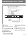
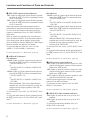
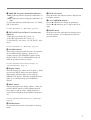
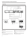
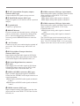
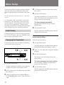
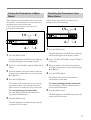
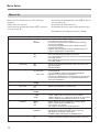
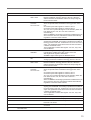
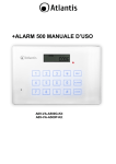
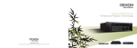
DIGITAL SATELLITE MODULATOR DSM-T1 OPERATION MANUAL [English] 1st Edition Serial No. 10001 and Higher For the customers in the United Kingdom WARNING To prevent fire or shock hazard, do not expose the unit to rain or moisture. To avoid electrical shock, do not open the cabinet. Refer servicing to qualified personnel only. For the customers in the USA This equipment has been tested and found to comply with the limits for a Class A digital device, pursuant to Part 15 of the FCC Rules. These limits are designed to provide reasonable protection against harmful interference when the equipment is operated in a commercial environment. This equipment generates, uses, and can radiate radio frequency energy and, if not installed and used in accordance with the instruction manual, may cause harmful interference to radio communications. Operation of this equipment in a residential area is likely to cause harmful interference in which case the user will be required to correct the interference at his own expense. You are cautioned that any changes or modifications not expressly approved in this manual could void your authority to operate this equipment. The shielded interface cable recommended in this manual must be used with this equipment in order to comply with the limits for a digital device pursuant to Subpart B of Part 15 of FCC Rules. WARNING: THIS WARNING IS APPLICABLE FOR USA ONLY. If used in USA, use the UL LISTED power cord specified below. DO NOT USE ANY OTHER POWER CORD. Plug Cap Cord Length Rating Parallel blade with ground pin (NEMA 5-15P Configuration) Type SJT, three 16 or 18 AWG wires Less than 2.5 m (8 ft. 3 in.) Minimum 10A, 125 V Using this unit at a voltage other than 120 V may require the use of a different line cord or attachment plug, or both. To reduce the risk of fire or electric shock, refer servicing to qualified service personnel. 2 WARNING THIS APPARATUS MUST BE EARTHED IMPORTANT This wires in this mains lead are coloured in accordance with the following code: Green-and-yellow:Earth Blue: Neutral Brown: Live As the colours of the wires in the mains lead of this apparatus may not correspond with the coloured markings identifying the terminals in your plug proceed as follows: The wire which is coloured green-and-yellow must be connected to the terminal in the plug which is marked by the letter E or by the safety earth symbol Y or coloured green or green-and-yellow. The wire which is coloured blue must be connected to the terminal which is marked with the letter N or coloured black. The wire which is coloured brown must be connected to the terminal which is marked with the letter L or coloured red. Table of Contents Features ...................................................................................................... 4 Locations and Functions of Parts and Controls ..................................... 5 Front Panel ........................................................................................... 5 Rear Panel ............................................................................................ 8 Menu Setup .............................................................................................. 10 Initial Display ..................................................................................... 10 Changing the Parameters .................................................................... 10 Saving the Parameters in Menu Banks ............................................... 11 Recalling the Parameters from Menu Banks ...................................... 11 Menu List ........................................................................................... 12 Connection ................................................................................................ 14 Operation Warnings ................................................................................ 15 Error Messages ................................................................................... 15 Warning Messages ............................................................................. 15 Specifications ............................................................................................ 16 3 Features The DSM-T1 Digital Satellite Modulator modulates analog video and audio input signals into digital signals. This modulator enables an SNG (Satellite News Gathering) system in combination with the DSM-R1 Digital Satellite Demodulator. The following are some of the features of the DSM-T1. Easy Installation The DSM-T1 provides easy connection with an existing SNG system via IF OUT (Intermediate Frequency output). High quality compression algorithm MPEG2 4:2:2 profile at Main Level (4:2:2 P@ML) ensures superior picture quality at 18 MHz transmission bandwidth. Direct digital transmission at up to twice real time The DSM-T1 enables transmission at up to twice real time speed at 36 MHz transmission bandwidth with connection of a DNW-A100/A100P digital video cassette recorder through the SDTI 1) (Serial Data Transport Interface). This feature contributes to increase of news gathering productivity. Optional interface boards available The BKSM-T101 SDTI Input Board, the BKSM-T102 SDI Input Board, and the BKSM-T103 Analog Input Board provide flexible choices of installing one or two boards to this unit. Two-program Transmission Two multiplexed video and audio signals can be transmitted simultaneously at 36 MHz transmission bandwidth. This contributes to lower transmission costs. ○ ○ ○ ○ ○ ○ ○ ○ ○ ○ ○ ○ ○ ○ ○ ○ ○ ○ ○ 1) SDTI is defined as SMPTE 305M. 4 ○ ○ ○ ○ ○ ○ ○ ○ ○ ○ ○ ○ ○ ○ ○ ○ ○ ○ ○ ○ ○ ○ ○ ○ ○ ○ ○ ○ ○ ○ ○ ○ ○ ○ ○ ○ ○ ○ ○ ○ ○ ○ ○ ○ ○ Locations and Functions of Parts and Controls Front Panel 1 POWER switch 2 PANEL INH indicator and switch 3 OPTION indicators 4 INPUT SEL indicators 5 AUDIO SEL indicators 6 REF indicators 7 VIDEO STD indicators 8 FREQ BW indicators 9 FEC RATE indicators !º ALARM indicator POWER PANEL INH OPTION 1 SDTI SDI ANALOG INPUT SEL AUDIO SEL CH1/2 CH3/4 IN1 VIDEO STD REF IN1 EXT 525 FREQ BW 36M FEC RATE ALARM MENU ITEM 7/8 ENTER ¬ IN2 IN2 625 18M 3/4 RESET !¡ Display window !™ MENU button !£ ENTER button !¢ ITEM Â/µ buttons !∞ Cursor (4/$/“/”) buttons !§ RESET button 1 POWER switch Turns the power on and off. 2 PANEL INH (inhibiting panel buttons) indicator and switch Set the PANEL INH switch to ON to deactivate the MENU, ENTER, ITEM Â/µ, and cursor (4/$/“/”) buttons. When the PANEL INH switch is set to ON, the PANEL INH indicator lights up. 3 OPTION (optional boards) indicators IN1 indicators SDTI: Lights up when the BKSM-T101 SDTI Input Board is installed in the IN1 section of the unit. SDI: Lights up when the BKSM-T102 SDI Input Board is installed in the IN1 section of the unit. ANALOG: Lights up when the BKSM-T103 Analog Input Board is installed in the IN1 section of the unit. IN2 indicators SDTI: Lights up when the BKSM-T101 SDTI Input Board is installed in the IN2 section of the unit. SDI: Lights up when the BKSM-T102 SDI Input Board is installed in the IN2 section of the unit. ANALOG: Lights up when the BKSM-T103 Analog Input Board is installed in the IN2 section of the unit. (Continued) 5 Locations and Functions of Parts and Controls 4 INPUT SEL (input selection) indicators IN1: Lights up when input signals from the optional board in the IN1 section are transmitted from the IF OUT connector. IN2: Lights up when input signals from the optional board in the IN2 section are transmitted from the IF OUT connector. When input signals from both optional boards are simultaneously transmitted, both indicators light up. To select from which optional board section input signals are transmitted, select “01: INPUT SELECT” in the menu. When no signals are supplied to the selected board slots, the indicator flashes. If the destination address of the input signals and the address selected in the menu are different when the BKSM-T101 SDTI Input Board is installed, the indicator also flashes. To select the address of this unit, select “43: My ADDR-1”“53:MY ADDR-2” in the menu. For more information, see “Menu Setup” (page 10). 5 AUDIO SEL indicators IN1 indicators CH1/2: Lights up if input signals from the optional board in the IN1 section are transmitted when; - The FEC RATE is 7/8 or - The FEC RATE is 3/4 and IN1 AUDIO CH is CH1/CH2. CH3/4: Lights up if input signals from the optional board in the IN1 section are transmitted when; - The FEC RATE is 7/8 or - The FEC RATE is 3/4 and IN1 AUDIO CH is CH3/CH4. When the BKSM-T103 Analog Input Board is installed and 3-pin XLR connectors are used, the indicator does not light regardless of the FEC RATE selection. To select the FEC rate, select “12: FEC RATE” in the menu. To select the audio channels for the optional board in the IN1 section, select “47: IN1 AUDIO CH” in the menu. For more information, see “Menu Setup” (page 10). IN2 indicators CH1/2: Lights up if input signals from the optional board in the IN2 section are transmitted when; - The FEC RATE is 7/8 or - The FEC RATE is 3/4 and IN2 AUDIO CH is CH1/CH2. CH3/4: Lights up if input signals from the optional board in the IN2 section are transmitted when; - The FEC RATE is 7/8 or - The FEC RATE is 3/4 and IN2 AUDIO CH is CH3/CH4. When the BKSM-T103 Analog Input Board is installed and 3-pin XLR connectors are used, the indicator does not light up regardless of the selection of the FEC RATE. To select the FEC rate, select “12: FEC RATE” in the menu. To select the audio channels for the optional board in the IN2 section, select “57: IN2 AUDIO CH” in the menu. For more information, see “Menu Setup” (page 10). 6 REF (reference signal) indicators IN1: Lights up when the reference signals are video signals from the input connectors of the optional board in the IN1 section. IN2: Lights up when the reference signals are video signals from the input connector of the optional board in the IN2 section. EXT: Lights up when the reference signals are video signals from the REF IN connector. With no signal supplied to the selected input connectors, the indicator flashes. To select the reference signals, select “02: REF SELECT” in the menu. For more information, see “Menu Setup” (page 10). 7 VIDEO STD (video standard) indicators 525: Lights up when the unit is set up in the 525 standard. 625: Lights up when the unit is set up in the 625 standard. To select the broadcasting standard, select “03: VIDEO STD” in the menu. For more information, see “Menu Setup” (page 10). 6 8 FREQ BW (frequency bandwidth) indicators 36M: Lights up when the frequency bandwidth is 36 MHz. 18M: Lights up when the frequency bandwidth is 18 MHz. To select the frequency bandwidth, select “11: FREQ BW” in the menu. !¢ ITEM Â/µ buttons Select the menu item when the menu is displayed in the display window. !∞ Cursor (4/$/“/”) buttons Use the 4 or $ button to change the parameters. Use the “ or ” button to move a digit to the left or right. For more information, see “Menu Setup” (page 10). 9 FEC RATE (Forward Error Correction rate) indicators 7/8: Lights up when the FEC rate is 7/8. 3/4: Lights up when the FEC rate is 3/4. To select the FEC rate, select “12: FEC RATE” in the menu. !§ RESET button Resets the unit to the status present when the power has been turned on. Use a sharp-pointed object to press this button. For more information, see “Menu Setup” (page 10). !º ALARM indicator When a fault is detected while the unit is in operation, the ALARM indicator lights up. In this case, a warning message (0X WARNING) appears in the display window. The ALARM indicator turns off when the operation returns to normal. For more information about warning messages, see “Operation Warnings” (page 15). !¡ Display window Normally displays the output carrier frequency. When you press the MENU button, the menu appears. When all the indicators flash, an error message (ERROR-XX) appears. When the ALARM indicator lights up, a warning message (0X WARNING) appears. !™ MENU button Displays the menu in the display window. When you press the MENU button, its back lighting lights up. Press again to clear the menu. When the menu is cleared, the back lighting for the MENU button turns off. For more information about the menu, see “Menu Setup” (page 10). !£ ENTER button Saves the parameters in the current bank or memory banks. 7 Locations and Functions of Parts and Controls Rear Panel 1 IN1 section 2 IN2 section 3 REF IN connector 4 SPARE connector REF IN SPARE BREAKER ⁄ AC IN IF OUT MONITOR 5 IF OUT connector 6 IF MONITOR connector 7 y jack 8 BREAKER button 9 ~ AC IN socket The rear panel on each optional board BKSM-T101 SDTI (SX) Input Board SDTI BKSM-T102 SDI Input Board SDI BKSM-T103 Analog Input Board AUDIO (AES/EBU) CH 1/2 VIDEO CH1 CH 3/4 AUDIO CH2 3-pin XLR OUT DIGITAL OUTPUT IN IN DIGITAL INPUT !º SDTI connector !¢ AUDIO connectors !™ AUDIO (AES/EBU) connectors !¡ SDI connector ANALOG INPUT !£ VIDEO connector VIDEO AUDIO CH1/2 CH3/4 5-pin XLR IN ANALOG INPUT !∞ AUDIO connectors 1 IN1 section Install any one of the optional boards in this section. 2 IN2 section Install any one of the optional boards in this section. For more information about installing the optional boards, refer to the Installation Manual. 8 3 REF IN (reference signal input) connector (BNC type) Inputs the reference video signals from external equipment. 4 SPARE connector (D-sub 25 pin, female) This connector is for future use. 5 IF OUT (Intermediate Frequency output) connector (BNC type) Outputs modulated IF signals to an up-converter. 6 IF MONITOR connector (BNC type) Outputs IF signals to an IF monitor such as a spectrum analyzer. 7 y (ground) jack Connects to a ground wire. 8 BREAKER button Excessive current in the internal circuitry, will trip the primary circuit breaker, automatically cutting off the power. After checking that the problem has been corrected, press the BREAKER button to restore the power. 9 ~ AC IN socket Connects to an AC power outlet using the optional AC power cord. This socket accepts 100 to 240 V AC power. !¢ AUDIO connectors (XLR type, 3-pin, female) Input analog audio signals (2 channels) from the audio output connectors on the BVW-75/75P Video Cassette Recorder, etc. CH 1: Inputs analog audio signals on channel 1. CH 2: Inputs analog audio signals on channel 2. !∞ AUDIO connectors (XLR type, 5-pin, male) Input analog audio signals (4 channels) from the audio output connectors on the BVW-75/75P Video Cassette Recorder, etc. CH 1/2: Inputs analog audio signals on channel 1 and 2. CH 3/4: Inputs analog audio signals on channel 3 and 4. The 5-pin XLR type can be converted to the 3-pin XLR (2 channels) with the optional CCXA-53 audio cable. The ITT CANNON XLR-3-11-11 conversion adapter can be also used to convert to the 3-pin XLR. !º SDTI (Serial Data Transport Interface) connector (BNC type) Inputs digital video and audio signals in SDTI (SX) format from the SDTI output connector on the DNWA100/A100P Digital Video Hybrid Recorder, etc. !¡ SDI (Serial Digital Interface) connector (BNC type) Inputs digital video and audio signals in SDI format from the SDI output connector on the DVW-A500/ A500P Digital Video Cassette Recorder, etc. !™ AUDIO (AES/EBU) connectors (BNC type) Input 2-channel digital audio signals in AES/EBU format from the AES/EBU audio output connectors on external equipment. CH 1/2: Inputs AES/EBU audio signals on channels 1 and 2. CH 3/4: Inputs AES/EBU audio signals on channels 3 and 4. !£ VIDEO connector (BNC type) Inputs composite analog video signals from the video output connector on the BVW-75/75P Video Cassette Recorder, etc. 9 Menu Setup A menu is provided to set up the operating conditions of the unit. Menu items include basic items, items about the optional boards, items about the front panel, etc. 4 To change the parameters of other items, repeat steps 2 and 3. 5 Press the ENTER button. For more information about menu items, see “ Menu List” (page 12). A “current bank” and 8 “menu banks” are provided with the unit. The current bank can be used to store current parameters. The menu banks can be used to store up to 8 sets of parameters. Saving/recalling frequently used parameters in/from menu banks allows faster setting up of the unit’s operating conditions. The changed parameters are saved in the current bank. The contents of the current bank are saved even after the power is turned off. To cancel changing parameters Press the MENU button before pressing the ENTER button. 6 Initial Display Press the MENU button. The back lighting for the MENU button turns off, and the unit exits the menu. Switching the power on causes the selected parameter of “15: IF OUT LEVEL” and “16: CARRIER” on the menu to appear in the display window. Changing the Parameters To return the contents of the current bank to the factory setting Follow the procedure below. Follow the procedure below to change the parameters and save them in the current bank. 1 Press the MENU button. The back lighting for the MENU button lights up, and the menu appears in the display window. 1,6 INPUT SEL ALOG SDI AUDIO SDI AEB/EBU REF IN1 VIDEO STD EXT FREQ BW FEC RATE 525 36M 7/8 625 18M 3/4 2,4 MENU ALARM ITEM ENTER IN2 3 Press the ENTER button. The contents of the current bank return to the factory setting. 3,4 To cancel returning to the factory setting Press the MENU, ITEM Â or µ button before pressing the ENTER button. Press the MENU button. The back lighting for the MENU button lights up, and the menu appears in the display window. 2 Select a menu item to be changed using the ITEM Â or µ button. 3 Change the parameters using the 4 or $ button. Use the “ or ” button to move a digit to the left or right. 10 Select “93: FACTORY SET” using the ITEM Â or µ button. RESET 5 1 2 4 Press the MENU button. The back lighting for the MENU button turns off, and the unit exits the menu. Saving the Parameters in Menu Banks Menu banks are provided with the unit as well as the current bank. The menu banks can store the 8 sets of parameters saved in the current bank. Follow the procedure below to save the set of parameters in menu banks. 1,5 INPUT SEL ALOG SDI AUDIO SDI AEB/EBU REF IN1 VIDEO STD EXT FREQ BW FEC RATE 525 36M 7/8 625 18M 3/4 2 MENU ALARM Recalling the Parameters from Menu Banks Follow the procedure below to recall the set of parameters from the menu banks. 1,5 INPUT SEL ALOG 1 VIDEO STD EXT FREQ BW FEC RATE 525 36M 7/8 625 18M 3/4 MENU ALARM ITEM ENTER IN2 RESET ITEM 4 RESET 4 REF IN1 ENTER IN2 SDI AUDIO SDI AEB/EBU 2 3 1 3 Press the MENU button. The back lighting for the MENU button lights up, and the menu appears in the display window. Press the MENU button. The back lighting for the MENU button lights up, and the menu appears in the display window. 2 Select “92: RECALL BANK” using the ITEM Â or µ button. 2 Select “91: SAVE BANK” using the ITEM Â or µ button. 3 3 Select the number of the desired menu bank to recall the contents into the current bank using the 4 or $ button. Select the number of the menu bank in which the contents of the current bank to be saved using the 4 or $ button. 4 Press the ENTER button. 4 Press the ENTER button. The contents of the selected menu bank are recalled to the current bank. The contents of the current bank are saved in the selected menu bank. The contents of the menu bank are saved even after the power is turned off. To cancel recalling from the menu bank Press the MENU, ITEM Â or µ button before pressing the ENTER button. To cancel saving in the menu bank Press the MENU, ITEM Â or µ button before pressing the ENTER button. 5 5 Press the MENU button. The back lighting for the MENU button turns off, and the unit exits the menu. Press the MENU button. The back lighting for the MENU button turns off, and the unit exits the menu. 11 Menu Setup Menu List Menu items are classified as one of the following categories: • Basic items (01~ and 10~) • Items about an optional board in the IN1 section on the rear panel (40~) • Items about an optional board in the IN2 section on the rear panel (50~) • Items about the front panel (80~) • Items about the saving and recalling functions (90~) The parameters in bold print are factory settings. Item number 01 Item INPUT SELECT Parameter IN1 IN2 IN1&IN2 02 REF SELECT EXT IN1 IN2 Selects the reference signals. EXT: Video signals from the REF IN connector IN1: Video signals from the input connector of the optional board in the IN1 section. IN2: Video signals from the input connector of the optional board in the IN2 section. 03 VIDEO STD 525 625 Selects the broadcasting standard for which the unit is set up. 525: 525 standard 625: 625 standard 08 PASSWORD OFF ON 0000 0001 : FFFF FFFF Turns the password function on or off. When “ON” is selected, set the password. OFF: The DSM-R1 outputs normal video/audio signals regardless of the password of the DSM-R1. ON: Sets an 8 digits password. If the password of the unit does not match that of the DSM-R1, no video/audio signals will be output from the DSM-R1. 11 FREQ BW 36 MHz 18 MHz Selects the frequency bandwidth. 12 FEC RATE 7/8 3/4 Selects the Forward Error Correction rate. 14 IF FREQ 140 MHz 70 MHz Selects the output carrier frequency of the IF OUT connector. 15 IF OUT LEVEL 0dB..-10dB <-10dB -20dB Selects the output level of the IF OUT connector. In 0dB..-10dB mode, the level can be set from 0dB to -10dB in 1dB steps. In <-10dB mode, the level can be set from -10dB to -20dB, but the displayed parameter is <-10dB. 16 CARRIER QPSK OFF CW Selects whether or not to modulate the IF output signals. QPSK: Outputs QPSK modulated wave OFF: Outputs no IF signals CW: Outputs continuous (non modulated) wave 41 IN1 SDI AUDIO SDI AES/EBU Selects the digital audio input signals if the BKSM-T102 SDI Input Board is installed in the IN1 section of the unit. SDI: Digital audio signals in SDI format AES/EBU: Digital audio signals in AES/EBU format 42 IN1 EMPHASIS OFF ON Turns the audio emphasis function on or off if the BKSM-T103 Analog Input Board is installed in the IN1 section of the unit. 12 Function Selects either or both IN1 or IN2 section input signals to be transmitted from the IF OUT connector. IN1: The input signals from the optional board in the IN1 section are transmitted. IN2: The input signals from the optional board in the IN2 section are transmitted. IN1&IN2: The input signals from both optional boards in the IN1 and IN2 sections are transmitted. Item number Item Parameter Function 43 MY ADDR-1 0000 0000···FFFF Sets an address for the unit itself if the BKSM-T101 SDTI Input Board is installed in the IN1 section of the unit. When the address matches the destination address of the input signals, the unit receives them. 47 IN1 AUDIO CH CH1/CH2 CH3/CH4 ALL CH1-CH4 Selects the audio input signal channels to the IF OUT connector when an optional board is installed in the IN1 section of the unit. CH1/CH2: Inputs audio signals on channel 1 and 2. CH3/CH4: Inputs audio signals on channel 3 and 4. ALL CH1-CH4: Inputs audio signals on all channels. (When the FEC RATE is set to 7/8, ALL CH1-CH4 is selected automatically.) When the BKSM-T103 Analog Input Board is installed and 3-pin XLR connectors are used, CH1/CH2 is selected automatically regardless of the FEC RATE selection. 48 IN1 V SETUP 0.0%···7.5%···10.0% Sets the VIDEO SETUP volume to be removed from the input signals when the BKSM-T103 Analog Input Board is installed in the IN1 section of the unit. Select from 0.0% to 10.0% in 0.5% steps. The parameter should be the same as that of the OUT1 V SETUP of DSM-R1 menu. This is applicable to NTSC video signals. For PAL, only 0.0% can be selected. 51 IN2 SDI AUDIO SDI AES/EBU Selects the digital audio input signals if the BKSM-T102 SDI Input Board is installed in the IN2 section of the unit. SDI: Digital audio signals in SDI format AES/EBU: Digital audio signals in AES/EBU format 52 IN2 EMPHASIS OFF ON Turns the audio emphasis function on or off if the BKSM-T103 Analog Input Board is installed in the IN2 section of the unit. 53 MY ADDR-2 0000 0000···FFFF Sets an address for the unit itself if the BKSM-T101 SDTI Input Board is installed in the IN2 section of the unit. When the address matches the destination address of the input signals, the unit receives them. 57 IN2 AUDIO CH CH1/CH2 CH3/CH4 ALL CH1-CH4 Selects the audio input signal channels to the IF OUT connector when an optional board is installed in the IN2 section of the unit. CH1/CH2: Inputs audio signals on channel 1 and 2. CH3/CH4: Inputs audio signals on channel 3 and 4. ALL CH1-CH4: Inputs audio signals on all channels. (When the FEC RATE is set to 7/8, ALL CH1-CH4 is selected automatically.) When the BKSM-T103 Analog Input Board is installed and 3-pin XLR connectors are used, CH1/CH2 is selected automatically regardless of the FEC RATE selection. 58 IN2 V SETUP 0.0%···7.5%···10.0% Sets the VIDEO SETUP volume to be removed from the input signals when the BKSM-T103 Analog Input Board is installed in the IN2 section of the unit. Select from 0.0% to 10.0% in 0.5% steps. The parameter should be the same as that of the OUT2 V SETUP of DSM-R1 menu. This is applicable to NTSC video signals. For PAL, only 0.0% can be selected. 81 LCD CONTRAST 1···5···10 Adjusts the contrast of the display window. 82 LCD BACKLIGHT 1···5···10 Adjusts the brightness of the display window back lighting. 91 SAVE BANK 1···8 Selects the menu bank in which the parameters in the current bank are to be saved. 92 RECALL BANK 1···8 Selects the menu bank in which the parameters to be recalled are saved. 93 FACTORY SET --- Resets the parameters in the current bank to the factory setting. 13 Connection When using the 5-pin XLR connector, see also the next page. • For more information about connecting external equipment, refer to the equipment operation manuals. The illustration below shows a typical connection of the unit for digital Satellite News Gathering. • There are two kinds of connectors on the BKSM-T103 Analog Input Board, 3-pin XLR or 5-pin XLR connector. SDTI(SX) equipment SDI equipment Analog equipment BKSM-R101 SDTI(SX) Output Board BKSM-R102 SDI Output Board BKSM-R103 Analog Output Board Satellite link Low noise block converter DSM-R1 Digital Satellite Demodulator High power amplifier Signal generator (Sony Tektronix TSG-170A for the NTSC broadcasting standard, Sony Tektronix TSG-271 for the PAL broadcasting standard, etc.) Up converter to test signal output to signal output IF OUT Rear REF IN REF IN ⁄AC IN SPARE BREAKER AC power cord to a wall outlet ⁄ AC IN IF OUT MONITOR IF MONITOR to monitor input Spectrum analyser Any two When using the 3pin XLR connector BKSM-T101 SDTI(SX) Input Board BKSM-T102 SDI Input Board SDTI SDI AUDIO (AES/EBU) CH 1/2 IN IN DIGITAL INPUT SDTI BKSM-T103 Analog Input Board CH 3/4 DIGITAL INPUT SDI to SDTI(SX) output DNW-A100/A100P Digital Video Hybrid Recorder, etc. VIDEO VIDEO CH1 IN AUDIO CH2 ANALOG INPUT AUDIO CH1 to analog to analog composite video audio output output (channel 1 or 3) BVW-75/75P Video Cassette Recorder, etc. to SDI output DVW-A500/A500P Digital Video Cassette Recorder, DNW-A100/A100P Digital Video Hybrid Recorder, DNW-7/7P Digital Camcorder with the CA-701 SDI Adaptor, etc. 14 AUDIO CH2 to analog audio output (channel 2 or 4) to reference signal input Operation Warnings When using the 5-pin XLR connector Error Messages Rear REF IN SPARE IF OUT MONITOR REF IN to test signal output For more information about error messages, refer to the Maintenance Manual. Signal generator (Sony Tektronix TSG-170A for the NTSC broadcasting standard, Sony Tektronix TSG-271 for the PAL broadcasting standard, etc.) to signal output BKSM-T103 Analog Input Board VIDEO VIDEO IN AUDIO CH1/2 CH3/4 AUDIO CH3/4 1) 1) to analog composite video output to analog to analog audio output audio output (channel 1 and 2) (channel 3 and 4) BVW-75/75P Video Cassette Recorder, etc. Warning Messages When a fault is detected while the unit is in operation, the ALARM indicator lights up and a warning message (0X WARNING) appears in the display window. When the operation returns to normal, the ALARM indicator turns off. Use the list below to check the meaning of the warning messages. ANALOG INPUT AUDIO CH1/2 When a fault is detected by the self-diagnosis function that automatically performs after the power is turned on, all the indicators flash and an error message (ERROR-XX) appears in the display window. The indicators do not turn off until the power is turned off. to reference signal input Warning number Message Meaning 01 FAN (REAR) STOP The rear fan has stopped running. 02 FAN (SW REG) STOP The internal fan has stopped running. 03 REF UNLOCK This unit is not synchronized with the reference signal selected with REF SELECT in the menu. 04 IN1 DATA OVERFLOW Inputted signals from the BKSM-T101 SDTI Input Board in the IN1 section have oveflowed and are not being transmitted. 05 IN2 DATA OVERFLOW Inputted signals from the BKSM-T101 SDTI Input Board in the IN2 section have oveflowed and are not being transmitted. 1) With the 5-pin XLR connector, use the optional CCXA-53 conversion audio cable or the conversion adapter. Setting a password If the PASSWORD is set to “ON” in the menu, set a password for the unit so that it matches that of the DSM-R1. If the password of the unit does not match that of the DSM-R1, the “PASSWORD INCORRECT” warning message appears in the display window of the DSM-R1 and no audio/video signals are output from the DSM-R1. If the PASSWORD is set to “OFF” in the menu, the DSM-R1 outputs the audio/video signals regardless of the password of the DSM-R1. For more information, see “Menu Setup” (page 10). 15 Specifications When the BKSM-T103 is installed: VIDEO: composite analog, BNC type × 1, 1.0 V p-p, 75 Ω REF IN: composite analog,BNC type × 1, 1.0 V p-p, 75 Ω General Power voltage Current consumption Operating temperature AC 100 to 240 V, 50/60 Hz 1.2 A to 0.6 A 0°C to 40°C (32°F to 104°F) Operating humidity 10% to 90% (non condensing) Storage temperature –20°C to +60°C (– 4°F to +140°F) Dimensions 424 × 43.6 × 525 mm (w/h/d) (16 3/4 × 1 3/4 × 20 3/4 inches) Mass 8 kg (17 lbs 10 oz) (when two BKSM-T102 are installed) Transmission mode IF bandwidth: 18 MHz 1 channel, real time IF bandwidth: 36 MHz 1 channel, twice real time (when the BKSM-T101 is installed) or 2 channels, real time Carrier bandwidth IF bandwidth: 18 MHz 18 MHz at –40 dB point IF bandwidth: 36 MHz 36 MHz at –40 dB point Modulation QPSK IF (Intermediate Frequency) 70 or 140 MHz selectable Error correction Reed-solomon + convolution (R=7/8, 3/4) Video characteristics Compression MPEG2 4:2:2P@ML Video input connectors When the BKSM-T101 is installed: SDTI (SX): BNC type × 1, 75 Ω SMPTE 305M When the BKSM-T102 is installed: SDI: BNC type × 1, 75 Ω SMPTE-259M/ ITU-R.BT.656-3 Audio characteristics Audio input connectors Channels/source Sampling frequency IF characteristics IF output connectors IF OUT: BNC type × 1, 75 Ω, –20 dBm to 0 dBm, 70/140 MHz selectable IF MONITOR: BNC type × 1, 75 Ω, –10 dB for the IF OUT Supplied accessories Operating Manual (1) Installation Manual (1) 16 When the BKSM-T101 is installed: SDTI: SDTI-embedded When the BKSM-T102 is installed: AUDIO (AES/EBU): SDIembedded, BNC type × 1 or AES/EBU, BNC type × 2, selectable When the BKSM-T103 is installed: 3-pin XLR × 2 (female) AUDIO CH1: analog audio AUDIO CH2: analog audio +4 dBu, High impedance 5-pin XLR × 2 (male) AUDIO CH1/2: analog audio AUDIO CH3/4: analog audio +4 dBu, High impedance 4 (R=7/8), 2 (R=3/4) 16 bits/48 kHz Optional boards BKSM-T101 SDTI Input Board BKSM-T102 SDI Input Board BKSM-T103 Analog Input Board Optional accessories RMM-30 Rack Mount Rail CCXA-53 conversion audio cable (5-pin XLR ˜ 3-pin XLR × 2) Design and specifications are subject to change without notice. 17 18 DSM-T1(SY, ) 3-860-007-01(1) Sony Corporation Broadcasting and Professional Systems Company Printed in Japan 1998.03.13 1998