1
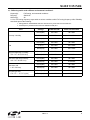
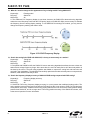
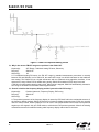
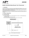
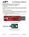
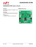
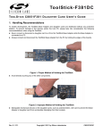
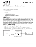
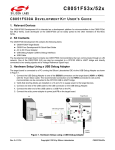
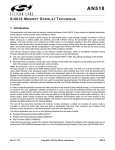
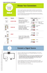
Si4831/35 AM/FM/SW TUNER F REQUENTLY A SKED Q UESTIONS Rev. 0.1 4/11 Copyright © 2011 by Silicon Laboratories Si4831/35 FAQ Rev. 0.1 4/11 Copyright © 2011 by Silicon Laboratories Si4831/35 FAQ S i 4 8 3 1 / 3 5 FA Q S I 4 8 3 1 / 3 5 A M / F M / S W TU N E R —F R E Q U E N T L Y ASKED QUESTIONS Table of Contents What's the advantage of using PVR tuning instead of PVC? . . . . . . . . . . . . . . . . . . . . . . . . . . 4 PVR tuning stable under different environmental conditions? . . . . . . . . . . . . . . . . . . . . . . . . . 5 What do I need to change on the appearance of my existing model if using Si4831/35? . . . . 6 How is the tuning feel of PVR with Si4831/35, is it easy to tune exactly to a station? . . . . . . . 6 How is the frequency display accuracy of Si4831/35 PVR tuning compared with PVC tuning? . . . . . . . . . . . . . . . . . . . . . . . . . . . . . . . . . . . . . . . . . . . . . . . . . . . 6 Why are some of my Si4831/35 models occasionally unable to power up after quick power off/on cycles? . . . . . . . . . . . . . . . . . . . . . . . . . . . . . . . . . . . . . . . . . . . . . . . . 7 Why is the measured SNR and Sensitivity often better when using an audio analyzer than when using a multimeter? 9 If my application is mono audio, how should I use Si4831/35? . . . . . . . . . . . . . . . . . . . . . . . . 9 When switching on the power supply, there is a small but audible power on pop noise. How can this pop noise be mitigated? . . . . . . . . . . . . . . . . . . . . . . . . . . . . . . . . . . . . . . . . . . . 9 Why is the narrow FM AFC range not a problem in the Si4831/35? . . . . . . . . . . . . . . . . . . . 10 How do I minimize the frequency display position hysteresis with PVR tuning? . . . . . . . . . . 10 Rev. 0.1 4/11 Copyright © 2011 by Silicon Laboratories Si4831/35 FAQ Si4831/35 FAQ Q: What's the advantage of using PVR tuning instead of PVC? Keyword(s): Device(s): HW Rev(s): PVR, PVC, resistance ratio Si4831/35 All A: PVR tuning has the following advantages compared with PVC tuning: 1. Cost saving Material cost: PVR is $0.05 vs. PVC for $0.12 for the same quantity and quality cost 2. Reliable life time and endurance (test proven) is better than PVC Labor Test Method: 100,000 PVR full range rotations SNR, sensitivity at three frequency points remain unchanged before and after rotation test SINAD, Before Test FM Test Points(MHz) After Test SINAD (dB) S/N (dB) Sensitivity (dBµV) SINAD (dB) S/N (dB) Sensitivity (dBµV) 88.1 57 58 2 57 58 2 98.1 57 58 2 57 58 2 107.9 56 57 3 56 57 3 PVR value and the frequency display mark stay within spec: 10K times rotations, PVR value stays the same, frequency/display alignment unchanged After 100K times rotations, PVR value changes less than10%, no visible change to frequency/display alignment. This is because Si4831/35 uses resistance ratio, not the absolute resistance value, for tuning to ensure display accuracy After Figure 1. PVR Resistance Ratio 4 Rev. 0.1 Si4831/35 FA Q Q: PVR tuning stable under different environmental conditions? Keyword(s): Device(s): HW Rev(s): PVR tuning, environmental conditions Si4831/35 All A. Yes, PVR tuning frequency stays stable at various conditions while PVC tuning frequency drifts. Reliability test results proved the following: Testing Tuned platform: Si4835-DEMO with R121 PVR and Sony clock radio ICF-C218 with PVC frequency is determined at maximum SINAD and S/N point Tests Hot temp / Humidity Cold Long term high temp / humidity (T = 60° C/H = 90%/100 Hour) Short term high temp /humidity (T = 60° C/H = 80%/6 Hour) Short term cold (T = –25° C/6 Hour) Hot /cold cycle test (T = 70° C/T = –10° C/5 cycles) Settings Si4831/35 PVR SONY–ICF-C218 PVC Room(start) 98.1 MHz 98.1 MHz T:45 °C,H:80% 98.1 MHz 98.14 MHz Room(end) 98.1 MHz 98.1 MHz Room(start) 98.1 MHz 98.1 MHz T:–10 °C 98.1 MHz 98.17 MHz Room(end) 98.1 MHz 98.17 MHz Room(start) 98.1 MHz 98.1 MHz Room(end) 98.1 MHz 98.28 MHz Room(start) 98.1 MHz 98.1 MHz Room(end) 98.1 MHz 97.98 MHz Room(start) 98.1 MHz 98.1 MHz Room(end) 98.1 MHz 98.1 MHz Room(start) 98.1 MHz 98.1 MHz Room(end) 98.1 MHz 98.06 MHz Rev. 0.1 5 Si4831/35 FAQ Q: What do I need to change on the appearance of my existing model if using Si4831/35? Keyword(s): Device(s): HW Rev(s): Existing model Si4831/35 All A. The traditional PVC frequency display is non-linear; however, the Si4831/35's advanced tuning algorithm makes the tuned frequency linear with the PVR turning angle, so Si4831/35 offers more accuracy to estimate the frequency from the analog display marking. To use Si4831/35 for existing PVC models, you only need to change the frequency marking and make it linear. Figure 2. PVC PVR Frequency Display Q: How is the tuning feel of PVR with Si4831/35, is it easy to tune exactly to a station? Keyword(s): Device(s): HW Rev(s): Tuning feel Si4831/35 All A: Compared with Si4830/34-A20, the Si4831/35 uses a new tuning algorithm that allows the user to hear one station across a larger frequency range. At the same time, the user can easily feel or tell if the tuned position is the best by the sound. The new tuning algorithm was added to improve the tuning feel and has been well received in the marketplace. The algorithm was carefully optimized such that selectivity was not compromised; therefore, weak station is still easy to tune. Q: How is the frequency display accuracy of Si4831/35 PVR tuning compared with PVC tuning? Keyword(s): Device(s): HW Rev(s): Frequency display accuracy Si4831/35 All A: Si4831/35 PVR tuning frequency display accuracy is not any worse than traditional analog radios. The tuning position inaccuracy has most to do with the PVR itself, but this is not unique to PVR. PVC will also have some position inaccuracy. Traditional PVC tuning analog radio has a much more severe tuned position drifting problem than Si4831/35, and for a longer term. PVR tuning position accuracy of the Si4831/35 is better; refer to the second question for more information. 6 Rev. 0.1 Si4831/35 FA Q Q: Why are some of my Si4831/35 models occasionally unable to power up after quick power off/on cycles? Keyword(s): Device(s): HW Rev(s): Power off/on cycles, power up, reset, reset pulse Si4831/35 All A: Sometimes, when the power switch is turned off/on quickly, or the power plug is plugged in/out quickly, the Si4831/35 can't be powered up properly and it can't go into normal working mode. The reason for this is that, during this type of fast power off/on process, the chip occasionally is not reset properly. Si4831/35 is digital in nature—an MCU and a DSP are integrated inside the chip. To power up properly, the chip needs a proper negative reset pulse during the quick power off/on cycle. As shown in Figure 3, the needed pulse width of tSRST is several ms. Because there are large filtering capacitors in the power supply circuit, the dc supply voltage VCC to tuner is still present (even though the main plug is disconnected) and falls down slowly. Accordingly, the RST pin voltage falls down slowly, so there is no needed reset pulse generated. Figure 5 shows a typical VCC and RST voltage change curve during a power off /on cycle. In this case, the RST voltage level doesn't drop below 0.3 VCC, so the chip is not reset properly and can't be powered up and go into normal working mode. tSRST RST 70% 30% Figure 3. Reset Pulse for Si4831/35 VCC R6 100k C19 0.1µ 13 14 15 GND GND RST Figure 4. RC Reset Circuit of Si4831/35 Rev. 0.1 7 Si4831/35 FAQ Figure 5. VCC (green) and RST (yellow) Change During Power Off Figure 6. Typical Power Supply Circuit Figure 6 shows the typical power supply circuit of a tuner; the solution to the power up issue is: 1. Add a discharge resistor at the output of tuner power supply to speed up the discharge process when the power is off. 2. Optimize the filtering caps capacity to a small value. Si4831/35 consumes only around 20 mA current in normal working mode, so the power supply circuits do not need to contain a large value of filtering caps; normally, no more than 47 µF is recommended. 8 Rev. 0.1 Si4831/35 FA Q Q: Why is the measured SNR and Sensitivity often better when using an audio analyzer than when using a multimeter? Keyword(s): Device(s): HW Rev(s): Audio analyzer, multimeter, SNR, Sensitivity Si4831/35 All A: Normally, there are two kinds of instruments used for measuring SNR and Sensitivity: one is a professional audio analyzer and another is a multimeter or voltmeter, which can be a traditional needle display type or more modern digital display type. The voltmeter is low cost and is widely used by many audio customers. A typical voltmeter model is TVT-322. Using the audio analyzer, the measured SNR and sensitivity is normally better than when using a voltmeter for the following reasons: 1. The frequency bandwidth of an audio analyzer is narrower than a voltmeter’s bandwidth. Audio analyzer bandwidth is normally up to 22 kHz; this is the real audio signal bandwidth. For the voltmeter, the frequency bandwidth is much wider, and different models have different bandwidths, normally above 200 kHz. For the TVT322, the bandwidth is up to 1 MHz. Because of the wider frequency bandwidth, the voltmeter always measures a higher noise level than the audio analyzer and therefore has a lower SNR value and Sensitivity value. But for true audio measurement, the noise level above 22 kHz should not be counted as it is beyond the human ear frequency audible range. 2. The audio analyzer is a more advanced instrument than the voltmeter; it can measure signal level and noise level at the same time, and can directly calculate SNR data. For the voltmeter, SNR data can only be obtained by first turning on modulation to get the signal level, then turning off modulation to get the noise level, and then calculating SNR data as the delta. So for the voltmeter, the measured signal level and noise level do not occur at the same time, hence it is not a true SNR measurement. Q: If my application is mono audio, how should I use Si4831/35? Keyword(s): Device(s): HW Rev(s): Mono Audio, Stereo Audio Si4831/35 All A: The Si4831/35 is a stereo audio tuner with two stereo thresholds: 20 dBµV and 28 dBµV. When the input RF level is below the selected stereo threshold, the chip outputs mono audio. When the input RF signal is above the selected stereo threshold, it automatically outputs stereo audio. The following measures are recommended for mono audio applications: 1. Choose the wanted FM band with stereo indication threshold of 28 dBµV. 2. Connect Lout and Rout together right after the AC coupling capacitors of 4.7 µF. Q: When switching on the power supply, there is a small but audible power on pop noise. How can this pop noise be mitigated? Keyword(s): Device(s): HW Rev(s): Pop noise Si4831/35 All A. Compared with Si4830/34-A20, the Si4831/35 has greatly reduced the power on pop noise. To further migrate the pop noise, the following measures are recommended: 1. The ac coupling capacitors in series with Lout and Rout of Si4831/35 must be no less than 4.7uF. 2. Normally, there is a large power supply filtering capacitor at the power supply of audio AMP, put the capacitor as close to the power supply pin of audio AMP as possible, and give this capacitor a large value, so that at power up, audio AMP starts up more slowly than Si4831/35, this will make the power on pop noise smaller. 3. To completely remove the power on pop noise, adding a transistor + E-cap muting circuit as shown in Figure 7 to Lout and Rout of Si4831/35 respectively. Rev. 0.1 9 Si4831/35 FAQ Figure 7. Power On Pop Noise Muting Circuit Q: Why is the narrow FM AFC range not a problem in the Si4831/35? Keyword(s): AFC Range, Traditional Analog FM tuner, Selectivity Device(s): Si4831/35 HW Rev(s): All A. For traditional analog FM tuners, the FM AFC range by standard measurement procedures is normally between 150 and 500 kHz, but for Si4831/35, the tested AFC range is at 40–60 kHz based on the traditional test method. The Si4831/35 has a digital architecture with an advanced tuning algorithm; therefore, it has dynamic AFC range. When PVR is rotated during tuning, Si4831/35 broadens its AFC range to around +/-500 kHz for easy station capturing and locking. When tuning is stopped, Si4831/35 automatically narrows its AFC range to 40–60 kHz for excellent selectivity performance. Q: How do I minimize the frequency display position hysteresis with PVR tuning? Keyword(s): Position Hysteresis, Frequency Display, PVR tuning Device(s): Si4831/35 HW Rev(s): All A. The position hysteresis of the frequency display is caused by PVR itself and/or the mechanical structure of the frequency display method. Si4831/35 itself has no frequency display hysteresis issue. PVRs are normally used for volume control, where hysteresis is not an issue. Test results showed some PVRs have hysteresis angles up to 4-5 degrees. Ask your PVR vendor to minimize the PVR position hysteresis. Most of the existing mechanical structures for traditional analog radio frequency display method also fix the issue. 10 Rev. 0.1 Si4831/35 FA Q NOTES: Rev. 0.1 11 Si4831/35 FAQ CONTACT INFORMATION Silicon Laboratories Inc. 400 West Cesar Chavez Austin, TX 78701 Tel: 1+(512) 416-8500 Fax: 1+(512) 416-9669 Toll Free: 1+(877) 444-3032 Please visit the Silicon Labs Technical Support web page: https://www.silabs.com/support/pages/contacttechnicalsupport.aspx and register to submit a technical support request. The information in this document is believed to be accurate in all respects at the time of publication but is subject to change without notice. Silicon Laboratories assumes no responsibility for errors and omissions, and disclaims responsibility for any consequences resulting from the use of information included herein. Additionally, Silicon Laboratories assumes no responsibility for the functioning of undescribed features or parameters. Silicon Laboratories reserves the right to make changes without further notice. Silicon Laboratories makes no warranty, representation or guarantee regarding the suitability of its products for any particular purpose, nor does Silicon Laboratories assume any liability arising out of the application or use of any product or circuit, and specifically disclaims any and all liability, including without limitation consequential or incidental damages. Silicon Laboratories products are not designed, intended, or authorized for use in applications intended to support or sustain life, or for any other application in which the failure of the Silicon Laboratories product could create a situation where personal injury or death may occur. Should Buyer purchase or use Silicon Laboratories products for any such unintended or unauthorized application, Buyer shall indemnify and hold Silicon Laboratories harmless against all claims and damages. Silicon Laboratories and Silicon Labs are trademarks of Silicon Laboratories Inc. Other products or brandnames mentioned herein are trademarks or registered trademarks of their respective holders. 12 Rev. 0.1