1
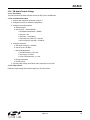
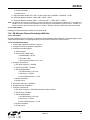
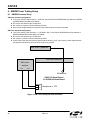
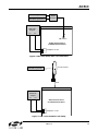
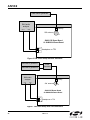
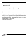
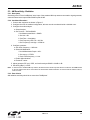
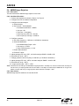
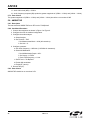
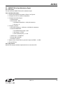
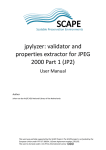
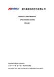
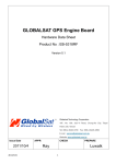
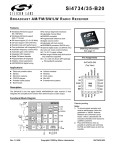
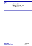
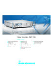
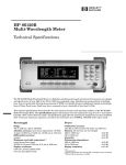
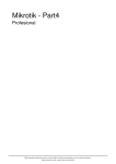
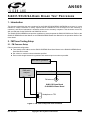
AN569 Si4831/35/20/24-D EMO B OARD TEST P ROCEDURE 1. Introduction This document describes the test procedures for the Si4831/35/20/24-DEMO AM/FM/SW tuner board. It is also intended to enable customers to exactly replicate Silicon Laboratories’ test environment so that variances in customers’ and Silicon Laboratories’ measured results can be accurately compared. This document covers FM, AM, and SW tests for the Si4831/20 and Si4835/24 receiver. The Si4831/35/20/24-DEMO board provides a platform to test and operate the Si4831/35/20/24 tuner. Refer to the Si4831/35-DEMO Board User Manual or the Si4820/24-DEMO Board User Manual for the operation details of the demo board. 2. FM Tuner Testing Setup 2.1. FM Common Setup FM tuner standard configuration: Tune exactly to 98.0 MHz; see the Si4831/35-DEMO Board User Manual or the Si4820/24-DEMO Board User Manual for details. Set volume to maximum unless otherwise specified. Ensure cable length between the generator and antenna input is as short as possible. R&S SML01 generator R&S audio analyzer CH1 AM Ferrite J1 CH2 FM antenna Si4831/35 Demo Board Or Si4820/24 Demo Board Lout Rout Headphone or TP3 Figure 1. FM Tuner Setup with One Generator Rev. 0.2 10/11 Copyright © 2011 by Silicon Laboratories AN569 AN569 R&S SML01 generator 1 Power Combiner R&S SML01 generator 2 AM Ferrite R&S audio analyzer CH1 J1 CH2 FM antenna Si4831/35 Demo Board Or Si4820/24 Demo Board Lout Rout Headphone or TP3 Figure 2. FM Tuner Setup with Two Generators FM tuner test equipment lists: Rohde & Schwarz UPL Audio Analyzer. Rohde &Schwarz SML01 Signal Generator Mini-Circuits Power Combiner 2.2. FM Tuner Testing Considerations Several issues must be considered to make accurate measurements. First, the power combiner and cable losses must be calibrated and factored into each measurement. The loss for the Mini-Circuit power combiner is approximately 6 dB. Second, most signal generators display the voltage generated at the input of the device under test (DUT), assuming an input resistance of 50 . For example, if the signal generator displays VL = 1 μV (0 dBμV), the generator source voltage VS is 2 μV (6 dBμV). The load voltage VL is generated from the source voltage VS by the voltage divider created by the 50 generator source resistance RS and the 50 load resistance RL. This distinction is important only for sensitivity, RDS sensitivity, and IP3, which are specified in μV EMF*, where EMF refers to the source voltage VS. Measurements such as AM suppression, selectivity, and spurious response are relative and may be referenced using VS or VL. To summarize, the generator displays the voltage at the input of the DUT. In the case of Si4831/35/20/24 FM tuner, input impedance is high so to convert the value displayed on the signal generator to EMF, double the voltage (add 6 dB). *Note: EMF = Electro Motive Force 2 Rev. 0.2 AN569 3. FM Testing Procedure 3.1. FM Tuning Frequency Range 3.1.1. Description The test checks the lowest possible tuning frequency and the highest possible tuning frequency of Si4831/35/20/24 FM receiver. 3.1.2. Conditions/Procedure 1. Connect test equipment as shown in Figure 1. 2. Configure the tuner in standard configuration. 3. Configure the audio analyzer: a. Select Analyze. b. Set Function = THD+N/SINAD. i. Set Measurement Mode = SINAD. ii. Set Unit = dB. iii. Set Filter = A-weighting. iv. Set Frequency Limit Low = 300 Hz. v. Set Frequency Limit High = 15000 Hz. 4. Configure generator: a. Set RF level = 0 dBμV. b. Select FM Modulation. i. Set FM Deviation = 22.5 kHz. ii. Set source = LFGEN. iii. Set LFGEN frequency = 1 kHz. c. Enable modulation. d. Enable carrier. 5. Slide band switch to select FM1 band for testing. 6. Turn tuning wheel to the lowest possible position. 7. Adjust signal generator RF (by 10 kHz step), until the measured SINAD reaches maximum level. Record this RF frequency as the lowest tuning frequency Fmin. 8. Repeat for highest tuning frequency point Fmax. 9. Repeat for other FM band testing. 3.1.3. Pass Criteria Table 1. FM Frequency Range Parameter Min Max Unit FM1 Frequency Range 87 108 MHz FM2 Frequency Range 86.5 109 MHz FM3 Frequency Range 87.3 108.25 MHz FM4 Frequency Range 76 90 MHz FM5 Frequency Range 64 87 MHz Rev. 0.2 3 AN569 3.2. FM Sensitivity 3.2.1. Description Determine input level in dBµVemf to result in 26 dB SINAD in mono RX mode. 3.2.2. Conditions/Procedure 1. Connect test equipment as shown in Figure 1. 2. Configure the tuner in standard configuration. 3. Configure the audio analyzer: a. Select Analyze. b. Set Function = THD+N/SINAD. i. Set Measurement Mode = SINAD. ii. Set Unit = dB. iii. Set Filter = A-weighting. iv. Set Frequency Limit Low = 300 Hz. v. Set Frequency Limit High = 15000 Hz. 4. Configure generator: a. Set carrier frequency = 98 MHz. b. Select FM Modulation. i. Set FM Deviation = 22.5 kHz. ii. Set Source = LFGEN. iii. Set LFGEN frequency = 1 kHz. c. Enable modulation. d. Enable carrier. 5. Adjust generator RF level, VRF0, until audio analyzer SINAD = 26 dB ±1 dB. 6. Sensitivity (dBμVemf) = VRF0. 3.2.3. Pass Criteria FM sensitivity should be below 10 dBµVemf. 3.3. FM Image Rejection 3.3.1. Description The test measures the FM image rejection of the tuner. 3.3.2. Conditions/Procedure 1. Connect test equipment as shown in Figure 1. 2. Configure the tuner in standard configuration. 3. Configure the audio analyzer: a. Select Analyze. b. Set Function = THD+N/SINAD. i. Set Measurement Mode = SINAD. ii. Set Unit = dB. iii. Set Filter = A-weighting. iv. Set Frequency Limit Low = 300 Hz. v. Set Frequency Limit High = 15000 Hz. 4 Rev. 0.2 AN569 4. Configure generator: a. Set carrier frequency = 98 MHz. b. Select FM Modulation. i. Set FM Deviation = 22.5 kHz. ii. Set Source = LFGEN. iii. Set LFGEN frequency = 1 kHz. c. Enable modulation. d. Enable carrier. 5. Adjust generator RF level, VRF1, until audio analyzer SINAD = 26 dB ±1 dB. 6. Record the RF level = VRF1. 7. Change generator carrier frequency to 97.744 MHz 8. Adjust generator RF level*, VRF2, until audio analyzer SINAD = 26 dB ±1 dB. 9. Image rejection (dB) = VRF2 – VRF1. Note: Maximum RF level setting for the R&S SML01 signal generator is 120 dBμV. You cannot increase the RF level beyond this value. If you adjust generator RF level from VRF1 to 120 dBμV, the audio analyzer SINAD still can not get to the SINAD = 26 dB ±1 dB, and your image rejection will be better than 120 dBμV – VRF1. 3.3.3. Pass Criteria FM Image rejection should be more than 40 dB. 3.4. FM Selectivity –3 dB 3.4.1. Description The test measures the FM frequency offset range to the tuned station when output audio level drops by 3 dB. 3.4.2. Conditions/Procedure 1. Connect test equipment as shown in Figure 1. 2. Configure the tuner in standard configuration. 3. Configure the audio analyzer: a. Select Analyze. b. Set Function = THD+N/SINAD. i. Set Measurement Mode = SINAD. ii. Set Unit = dB. iii. Set Filter = A-weighting. iv. Set Frequency Limit Low = 300 Hz. v. Set Frequency Limit High = 15000 Hz. 4. Configure generator: a. Set carrier frequency = 98 MHz. b. Set RF level = 40 dBμV. c. Select FM Modulation. i. Set FM Deviation = 22.5 kHz. ii. Set Source = LFGEN. iii. Set LFGEN frequency = 1 kHz. d. Enable modulation. e. Enable carrier. 5. Record the audio output level (dBV) = VAUDIO0. 6. Raise the signal generator RF frequency Fh, until audio output level VAUDIO1 = VAUDIO0–3. Rev. 0.2 5 AN569 7. Lower the signal generator RF frequency Fl, until audio output level VAUDIO1 = VAUDIO0–3. 8. Selectivity –3 dB (kHz) = Fh – Fl. 3.4.3. Pass Criteria FM Selectivity for –3dB audio level difference should be between 40 kHz and 100 kHz. 3.5. FM Limiting –3 dB 3.5.1. Description The test measures the RF input level when audio output level drops by 3 dB from the standard level. 3.5.2. Conditions/Procedure 1. Connect test equipment as shown in Figure 1. 2. Configure the tuner in standard configuration. 3. Configure the audio analyzer: a. Select Analyze. b. Set Function = THD+N/SINAD. i. Set Measurement Mode = SINAD. ii. Set Unit = dB. iii. Set Filter = A-weighting. iv. Set Frequency Limit Low = 300 Hz. v. Set Frequency Limit High = 15000 Hz. 4. Configure generator: a. Set carrier frequency = 98 MHz. b. Set RF level = 94 dBμV. c. Select FM Modulation. i. Set FM Deviation = 22.5 kHz. ii. Set Source = LFGEN. iii. Set LFGEN frequency = 1 kHz. d. Enable modulation. e. Enable carrier. 5. Record the audio output level (dBV) = VAUDIO0. 6. Adjust the signal generator RF level VRF0, until audio output level VAUDIO1 = VAUDIO0–3. 7. FM limiting –3 dB (dBµV) = VRF0. 3.5.3. Pass Criteria FM Limiting sensitivity for –3 dB audio level drop should be no more than 3 dBµV. 6 Rev. 0.2 AN569 3.6. FM Audio Frequency Response 3.6.1. Description Audio frequency response is the measure of linearity of output voltage vs. modulation frequency across the audio band. 3.6.2. Conditions/Procedure 1. Connect test equipment as shown in Figure 1. 2. Configure the tuner in standard configuration. 3. Configure the audio analyzer: a. Select Analyze. b. Set Function = RMS Select. i. Set Bandwidth = BP 3%. ii. Set Units = dBV. iii. Set Frequency Mode = FIX: 1 kHz. 4. Configure generator: a. Set carrier frequency = 98 MHz. b. Set RF level = 60 dBμV. c. Select Stereo Modulation. i. Set FM Deviation = 10.5 kHz. ii. Set L = R. iii. Set Source = LFGEN. iv. Set LFGEN frequency = 1 kHz. v. Set Pre-emphasis = 75 μs. vi. Set Pilot = ON. vii. Set Pilot Deviation = 6.75 kHz. d. Enable modulation. e. Enable carrier. 5. Audio 1 kHz level (dBV) = V1 kHz. 6. Configure audio analyzer frequency mode through RMS Select Function. Set Frequency Mode = FIX: 30 Hz. 7. Configure generator LFGEN frequency = 30 Hz. 8. Audio 30 Hz level (dBV) = V30 Hz. 9. Configure audio analyzer frequency mode through RMS Select Function. Set Frequency Mode = FIX: 15 kHz. 10. Configure generator LFGEN frequency = 15 kHz. 11. Audio 15 kHz level (dBV) = V15 kHz. 12. Audio frequency response (dB) equals the greater magnitude of (V30 Hz – V1 kHz) and (V15 kHz – V1 kHz). Note: If you test the band with De-emphasis 50 μs, you should Set Pre-emphasis = 50 μs. 3.6.3. Pass Criteria The greater magnitude of (V30 Hz – V1 kHz) and (V15 kHz – V1 kHz) should be no more than 3 dB. Rev. 0.2 7 AN569 3.7. FM Stereo Separation 3.7.1. Description The test quantifies leakage or crosstalk from one channel to another in stereo mode. 3.7.2. Conditions/Procedure 1. Connect test equipment as shown in Figure 1. 2. Configure the tuner in standard configuration. 3. Configure the audio analyzer: a. Select Analyze. b. Set Function = RMS Select. i. Set Bandwidth = BP 3%. ii. Set Units = dBV. iii. Set Frequency Mode = FIX: 1 kHz. 4. Configure generator: a. Set carrier frequency = 98 MHz. b. Set RF level = 60 dBμV. c. Select Stereo Modulation. i. Set FM Deviation = 67.5 kHz. ii. Set L = 1, R = 0. iii. Set Source = LFGEN. iv. Set LFGEN frequency = 1 kHz. v. Set Pre-emphasis = 75 μs. vi. Set Pilot = ON. vii. Set Pilot Deviation = 6.75 kHz. d. Enable modulation. e. Enable carrier. 5. Left channel audio level (dBV) = VAUDIOL1. 6. Right channel audio level (dBV) = VAUDIOR1. 7. Record the Audio Stereo Separation1 (dB) = abs (VAUDIOL1 – VAUDIOR1). 8. Configure generator: a. Set carrier frequency = 98 MHz. b. Set RF level = 60 dBμV. c. Select Stereo Modulation. i. Set FM Deviation = 67.5 kHz. ii. Set L = 0, R = 1. iii. Set Source = LFGEN. iv. Set LFGEN frequency = 1 kHz. v. Set Pre-emphasis = 75 μs. vi. Set Pilot = ON. vii. Set Pilot Deviation = 6.75 kHz. d. Enable modulation. e. Enable carrier. 9. Left channel audio level (dBV) = VAUDIOL2. 10. Right channel audio level (dBV) = VAUDIOR2. 8 Rev. 0.2 AN569 11. Record the Audio Stereo Separation2 (dB) = abs (VAUDIOL2—VAUDIOR2). 12. Audio Stereo Separation (dB) = minimum (Audio Stereo Separation1, Audio Stereo Separation2) 3.7.3. Pass Criteria FM Stereo separation should be greater than 32 dB. 3.8. FM Audio L/R Imbalance 3.8.1. Description The test measures the gain/level imbalance between L and R channels in stereo mode. 3.8.2. Conditions/Procedure 1. Connect test equipment as shown in Figure 1. 2. Configure the tuner in standard configuration. 3. Configure the audio analyzer: a. Select Analyze. b. Set Function = RMS Select. i. Set Bandwidth = BP 3%. ii. Set Units = dBV. iii. Set Frequency Mode = FIX: 1 kHz. 4. Configure generator: a. Set carrier frequency = 98 MHz. b. Set RF level = 60 dBμV. c. Select FM Modulation. i. Set FM Deviation = 75 kHz. ii. Set RF level = 60 dBμV. iii. Set Source = LFGEN. iv. Set LFGEN frequency = 1 kHz. d. Enable modulation. e. Enable carrier. 5. Left channel audio level (dBV) = VAUDIOL. 6. Right channel audio level (dBV) = VAUDIOR. 7. Audio L/R imbalance (dB) = abs (VAUDIOL – VAUDIOR). 3.8.3. Pass Criteria FM audio L/R imbalance should be no more than 1 dB. Rev. 0.2 9 AN569 3.9. FM Tuning Indicator Sensitivity 3.9.1. Description The test measures the needed RF input level to turn on the tuning indicator. 3.9.2. Conditions/Procedure 1. Connect test equipment as shown in Figure 1. 2. Configure the tuner in standard configuration. 3. Configure the audio analyzer: a. Select Analyze. b. Set Function = THD+N/SINAD. i. Set Measurement Mode = SINAD. ii. Set Unit = dB. iii. Set Filter = A-weighting. iv. Set Frequency Limit Low = 300 Hz. v. Set Frequency Limit High = 15000 Hz. 4. Configure generator: a. Set carrier frequency = 98 MHz. b. Set RF level = 60 dBμV. c. Select FM Modulation. i. Set FM Deviation = 22.5 kHz. ii. Set source = LFGEN. iii. Set LFGEN frequency = 1 kHz. d. Enable modulation. e. Enable carrier. 5. Decrease signal generator RF level until the tuning indicator turns off. 6. Increase signal generator RF level VRF0 from low to high until tuning indicator turns on. 7. FM tuning indicator sensitivity = VRF0. 3.9.3. Pass Criteria FM tuning indicator sensitivity should be no more than 15 dBµV. 10 Rev. 0.2 AN569 3.10. FM Stereo Indicator Sensitivity 3.10.1. Description The test measures the needed RF input level to turn on the stereo indicator. 3.10.2. Conditions/Procedure 1. Connect test equipment as shown in Figure 1. 2. Configure the tuner in standard configuration. 3. Configure the audio analyzer: a. Select Analyze. b. Set Function = THD+N/SINAD. i. Set Measurement Mode = SINAD. ii. Set Unit = dB. iii. Set Filter = A-weighting. iv. Set Frequency Limit Low = 300 Hz. v. Set Frequency Limit High = 15000 Hz. 4. Configure generator: a. Set carrier frequency = 98 MHz. b. Set RF level = 60 dBμV. c. Select Stereo Modulation. i. Set FM Deviation = 22.5 kHz. ii. Set L = 1, R = 1. iii. Set Source = LFGEN. iv. Set LFGEN frequency = 1 kHz. v. Set Pre-emphasis = 75 μs. vi. Set Pilot = ON. vii. .Set Pilot Deviation = 6.75 kHz. d. Enable modulation. e. Enable carrier. 5. Decrease signal generator RF level until the tuning indicator turns off. 6. Increase signal generator RF level VRF0 from low to high until stereo indicator turns on. 7. FM stereo indicator sensitivity = VRF0. 3.10.3. Pass Criteria FM stereo indicator sensitivity should be 18~22 dBµV for bands with an FM stereo indicator threshold of 6 dB separation at 20 dBµV RF input. FM stereo indicator sensitivity should be 26~30 dBµV for bands with an FM stereo indicator threshold of 12 dB separation at 28 dBµV RF input. Rev. 0.2 11 AN569 3.11. FM Mono Distortion 3.11.1. Description The test measures THD in FM Mono mode with a fixed, moderate input signal strength. 3.11.2. Conditions/Procedure 1. Connect test equipment as shown in Figure 1. 2. Configure the tuner in standard configuration. 3. Configure the audio analyzer: a. Select Analyze. b. Set Function = THD. i. Set Measurement Mode = All di (all harmonics). ii. Select Unit = %. 4. 4. Configure generator: a. Set carrier frequency = 98 MHz. b. Select FM Modulation. i. Set FM Deviation = 75 kHz. ii. Set RF level = 60 dBμV. iii. Set source = LFGEN. iv. Set LFGEN frequency = 1 kHz. c. Enable modulation. d. Enable carrier. 5. Adjust volume control wheel to get audio output level RMS = –20 dBV. 6. Record THD (%). 3.11.3. Pass Criteria FM Mono distortion should be no more than 0.5%. 12 Rev. 0.2 AN569 3.12. FM Mono SNR 3.12.1. Description The test measures Signal to Noise ratio in FM mono mode at a fixed, moderate input signal strength. 3.12.2. Conditions/Procedure 1. Connect test equipment as shown in Figure 1. 2. Configure the tuner in standard configuration. 3. Configure the audio analyzer: a. Select Analyze. b. Set Function = THD+N/SINAD. i. Set Measurement Mode = Noise. ii. Set Unit = dB. iii. Set Filter = A-weighting. iv. Set Frequency Limit Low = 300 Hz. v. Set Frequency Limit High = 15000 Hz. 4. Configure generator: a. Set carrier frequency = 98 MHz. b. Set RF level = 60 dBμV. c. Select FM Modulation. i. Set FM Deviation = 22.5 kHz. ii. Set Source = LFGEN. iii. Set LFGEN frequency = 1 kHz. d. Enable modulation. e. Enable carrier. 5. Record SNR (dB) = Noise (dB). 3.12.3. Pass Criteria FM SNR should be more than 55 dB. Rev. 0.2 13 AN569 3.13. FM Radio AM Suppression 3.13.1. Description The test quantifies AM suppression by measuring the difference at the audio output between FM and AM modulated input signals. 3.13.2. Conditions/Procedure 1. Connect test equipment as shown in Figure 1. 2. Configure the tuner in standard configuration. 3. Configure the audio analyzer: a. Select Analyze. b. Set Function = RMS Select. i. Set Bandwidth = BP 3%. ii. Set Units = dBV. iii. Set Frequency Mode = FIX: 1 kHz. 4. Configure generator: a. Set carrier frequency = 98 MHz. b. Set RF level = 60 dBμV. c. Select FM Modulation. i. Set FM Deviation = 22.5 kHz. ii. Set Source = LFGEN. iii. Set LFGEN frequency = 1 kHz. d. Enable modulation. e. Enable carrier. 5. Record the audio level, VAUDIO0. 6. Turn off generator FM modulation. 7. Configure generator: a. Set carrier frequency = 98 MHz. b. Set RF level = 60 dBμV. c. Select AM Modulation. i. Set Depth = 30%. ii. Set Source = LFGEN. iii. Set LFGEN frequency = 1 kHz. d. Enable modulation. e. Enable carrier. 8. Record the audio level, VAUDIO1. 9. AM Suppression (dB) = VAUDIO0 – VAUDIO1. 3.13.3. Pass Criteria: FM radio AM suppression should be more than 40 dB. 14 Rev. 0.2 AN569 3.14. FM Audio Output Voltage 3.14.1. Description The test measures FM Audio Volume Level at an RF Level of 60 dBµVemf. 3.14.2. Conditions/Procedure 1. Connect test equipment as shown in Figure 1. 2. Configure the tuner in standard configuration. 3. Configure the audio analyzer: a. Select Analyze. b. Set Function = THD+N/SINAD. i. Set Measurement Mode = SINAD. ii. Set Unit = dB. iii. Set Filter = A-weighting. iv. Set Frequency Limit Low = 300 Hz. v. Set Frequency Limit High = 15000 Hz. 4. Configure generator: a. Set carrier frequency = 98 MHz. b. Set RF level = 60 dBμV. c. Select FM Modulation. i. Set FM Deviation = 22.5 kHz. ii. Set source = LFGEN. iii. Set LFGEN frequency = 1 kHz. d. Enable modulation. e. Enable carrier. 5. Test the audio voltage at FM tuner audio output pin Lout or Rout. 3.14.3. Pass Criteria FM audio output voltage level should range from 72 to 90 mVrms. Rev. 0.2 15 AN569 3.15. FM Adjacent Channel Selectivity (±200 kHz) 3.15.1. Description The test quantifies receiver vulnerability to adjacent-channel signals at offset ±200 kHz from desired signal. This is a data sheet specification; two signal generators and one power combiner are used in the test. 3.15.2. Conditions/Procedure 1. Connect test equipment as shown in Figure 2. 2. Configure the tuner in standard configuration. 3. Configure the audio analyzer: a. Select Analyze. b. Set Function = RMS Select. i. Set Bandwidth = BP 3%. ii. Set Units = dBV. iii. Set Frequency Mode = FIX: 1 kHz. 4. Configure generator #1: a. Set carrier frequency = 98 MHz. b. Set RF level VRF0 = 40 dBμV. c. Select FM Modulation. i. Set FM Deviation = 22.5 kHz. ii. Set source = LFGEN. iii. Set LFGEN frequency = 1 kHz. d. Enable modulation. e. Enable carrier. 5. Record the audio level, VAUDIO0. 6. Disable generator modulation. 7. Configure generator #2: a. Set carrier frequency = 98.2 MHz. b. Set RF level = 60 dBμV. c. Select FM Modulation. i. Set FM Deviation = 22.5 kHz. ii. Set source = LFGEN. iii. Set LFGEN frequency = 1 kHz. d. Enable modulation. e. Enable carrier. 8. Adjust generator #2 RF level*, VRF1, until the audio level, VAUDIO1 = VAUDIO0 – 30 dB. 9. Selectivity Adjacent Channel +200k (dB) = VRF1 – VRF0. 10. Configure generator #2: a. Set carrier frequency = 97.8 MHz. b. Set RF level = 60 dBμV. c. Select FM Modulation. i. Set FM Deviation = 22.5 kHz. ii. Set source = LFGEN. iii. Set LFGEN frequency = 1 kHz. 16 Rev. 0.2 AN569 d. Enable modulation. e. Enable carrier. 11. Adjust generator #2 RF level*, VRF2, until the audio level, VAUDIO1 = VAUDIO0 – 30 dB. 12. Selectivity Adjacent Channel –200 k (dB) = VRF2 – VRF0. 13. Selectivity Adjacent Channel ±200 k = minimum (VRF1 – VRF0, VRF2 – VRF0). *Note: Generator #1 RF level is set to 40 dBμV to be able to get selectivity results greater than 60 dB. This is not a limitation of the FM tuner or the evaluation board. Maximum RF level setting for the R&S SML01 signal generator is 120 dBμV. You cannot increase the RF level beyond this value, so if VRF0 = 60 dBμV, selectivity numbers would be limited to 60 dB. 3.15.3. Pass Criteria FM adjacent channel selectivity should be more than 50 dB. 3.16. FM Alternate Channel Selectivity (±400 kHz) 3.16.1. Description The test quantifies receiver vulnerability to alternate-channel signals at offset ±400 kHz from desired signal. This is a data sheet specification; two signal generators and one power combiner are used in the test. 3.16.2. Conditions/Procedure 1. Connect test equipment as shown in Figure 2. 2. Configure the tuner in standard configuration. 3. Configure the audio analyzer: a. Select Analyze. b. Set Function = RMS Select. i. Set Bandwidth = BP 3%. ii. Set Units = dBV. iii. Set Frequency Mode = FIX: 1 kHz. 4. Configure generator #1: a. Set carrier frequency = 98 MHz. b. Set RF level VRF0 = 40 dBμV. c. Select FM Modulation. i. Set FM Deviation = 22.5 kHz. ii. Set source = LFGEN. iii. Set LFGEN frequency = 1 kHz. d. Enable modulation. e. Enable carrier. 5. Record the audio level, VAUDIO0. 6. Disable generator modulation. 7. Configure generator #2: a. Set carrier frequency = 98.4 MHz (Alternate Channel +400 k). b. Set RF level = 60 dBμV. c. Select FM Modulation. i. Set FM Deviation = 22.5 kHz. ii. Set source = LFGEN. iii. Set LFGEN frequency = 1 kHz. d. Enable modulation. e. Enable carrier. Rev. 0.2 17 AN569 8. Adjust generator #2 RF level*, VRF1, until the audio level, VAUDIO1 = VAUDIO0 – 30 dB. 9. Selectivity Alternate Channel +400 k (dB) = VRF1 – VRF0. 10. Configure generator #2: a. Set carrier frequency = 97.6 MHz (Alternate Channel –400 k). b. Set RF level = 60 dBμV. c. Select FM Modulation. i. Set FM Deviation = 22.5 kHz. ii. Set source = LFGEN. iii. Set LFGEN frequency = 1 kHz. d. Enable modulation. e. Enable carrier. 11. Adjust generator #2 RF level*, VRF2, until the audio level, VAUDIO1 = VAUDIO0 – 30 dB. 12. Selectivity Alternate Channel –400 k (dB) = VRF2 – VRF0. 13. Selectivity Alternate Channel ±400 k = minimum (VRF1 – VRF0, VRF2 – VRF0). *Note: Generator #1 RF level is set to 40 dBμV to be able to get selectivity results greater than 60 dB. This is not a limitation of the FM tuner or the evaluation board. Maximum RF level setting for the R&S SML01 signal generator is 120 dBμV. You cannot increase the RF level beyond this value, so if VRF0 = 60 dBμV, selectivity numbers would be limited to 60 dB. 3.16.3. Pass Criteria FM alternate channel selectivity should be more than 60 dB. 18 Rev. 0.2 AN569 3.17. FM Stereo Pilot Rejection 3.17.1. Description Stereo pilot rejection is the quality criterion of a tuner that is measured as the ratio of wanted audio frequency voltage to pilot frequency voltage according to the equation: Pilot Rejection = Vaudio0 (1 kHz) + 20 log pilot f – Vaudio0 19 kHz where f is FM frequency deviation and pilot is pilot frequency deviation. 3.17.2. Conditions/Procedure 1. Connect test equipment as shown in Figure 1. 2. Configure the tuner in standard configuration. 3. Configure the audio analyzer: a. Select Analyze. b. Set Function = RMS Select. i. Set Bandwidth = BP 3%. ii. Set Units = dBV. iii. Set Frequency Mode = FIX: 1 kHz. 4. Configure generator: a. Set carrier frequency = 98 MHz. b. Set RF level = 60 dBμV. c. Select Stereo Modulation. i. Set FM Deviation = 67.5 kHz. ii. Set L = 1, R = 1. iii. Set Source = LFGEN. iv. Set LFGEN frequency = 1 kHz. v. Set Pre-emphasis = 75 μs. vi. Set Pilot = ON. vii. Set Pilot Deviation = 6.75 kHz. d. Enable modulation. e. Enable carrier. 5. Adjust volume control wheel to get audio output level RMS = –20 dBV. 6. Audio 1 kHz level (dBV) = V1 kHz. 7. Disable 1 kHz tone (by disabling 1 kHz source, not stereo mod). 8. Configure audio analyzer frequency mode = FIX: 19 kHz. 9. Audio 19 kHz level (dBV) = V19kHz. 10. Pilot Rejection (relative to pilot) (dB) = V1kHz – V19 kHz + 20*log10 (∆pilot/∆f) = V1kHz – V19 kHz – 20. 3.17.3. Pass Criteria FM Stereo pilot rejection should be more than 40 dB. Rev. 0.2 19 AN569 4. AM/SW Tuner Testing Setup 4.1. AM/SW Common Setup AM tuner standard configuration. Tune tuner exactly to AM frequency = 1000 kHz. See the Si4831/35-DEMO Board User Manual or Si4820/ 24-DEMO Board User Manual for details. RF Level at the antenna input 74 dBµVemf. Set volume to maximum unless otherwise specified. Ensure cable length between the generator and antenna input is as short as possible. SW tuner standard configuration. Tune tuner exactly to SW frequency = 11.85 MHz in SW 7. See Si4831/35-DEMO Board User Manual or Si4820/24-DEMO Board User Manual for details. RF Level at the antenna input 74 dBµVemf. Set volume to maximum unless otherwise specified. Connect SG to the antenna input through an antenna dummy (10 pF cap in series); cable length between the generator and antenna input should be as short as possible. R&S SML01 generator AMAM Ferrite Antenna Ferrite R&S audio analyzer CH1 CH2 J6 AM antenna Si4831/35 Demo Board Or Si4820/24 Demo Board Lout Rout Headphone or TP3 Figure 3. AM Tuner Setup with One Generator 20 Rev. 0.2 AN569 R&S SML01 generator 1 R&S SML01 generator 2 Power Combiner AMAM Ferrite Antenna Ferrite R&S audio analyzer CH1 CH2 J6 AM antenna Si4831/35 Demo Board Or Si4820/24 Demo Board Lout Rout Headphone or TP3 Figure 4. AM Tuner Setup with Two Generators Air loop antenna R&S SML01 generator 60cm AMAM Ferrite Ferrite Antenna R&S audio analyzer CH1 CH2 Si4831/35 Demo Board Or Si4820/24 Demo Board Lout Rout Headphone or TP3 Figure 5. AM Tuner Radiation Test Setup Rev. 0.2 21 AN569 R&S SML01 generator R&S audio analyzer CH1 AM Ferrite Dummy CH2 SW antenna J1 Si4831/35 Demo Board Or Si4820/24 Demo Board Lout Rout Headphone or TP3 Figure 6. SW Tuner Setup with One Generator R&S SML01 generator 1 Power Combiner R&S SML01 generator 2 AM Ferrite R&S audio analyzer CH1 Dummy CH2 SW antenna J1 Si4831/35 Demo Board Or Si4820/24 Demo Board Lout Rout Headphone or TP3 Figure 7. SW Tuner Setup with Two Generators 22 Rev. 0.2 AN569 AM/SW tuner test equipment lists: Rohde & Schwarz UPL Audio Analyzer &Schwarz SML01 Signal Generator Mini-Circuits Power Combiner SW Antenna Dummy Rohde Figure 8. SW Antenna Dummy Circuit 4.2. AM/SW Tuner Testing Considerations Several issues must be considered to make accurate measurements. First, the power combiner and cable losses must be calibrated and factored into each measurement. The loss for the Mini-Circuit power combiner is approximately 6 dB. Second, most signal generators display the voltage generated at the input of the device under test (DUT) assuming an input resistance of 50 Ω. For example, if the signal generator displays VL = 1 μV (0 dBμV), the generator source voltage VS is 2 μV (6 dBμV). The load voltage VL is generated from the source voltage VS by the voltage divider created by the 50 generator source resistance RS and the 50 load resistance RL. This distinction is important only for sensitivity, RDS sensitivity, and IP3, which are specified in μV EMF*, where EMF refers to the source voltage VS. Measurements such as AM suppression, selectivity, and spurious response are relative and may be referenced using VS or VL. To summarize, the generator displays the voltage at the input of the DUT. With the Si4831/35/20/24 AM/SW tuner, the input impedance is high, so the voltage needs to be doubled (add 6 dB) to convert the value displayed on the signal generator to EMF. For SW testing, connect the SG to the antenna input through an antenna dummy to simulate the characteristics of normal whip antenna at SW frequency band. Rev. 0.2 23 AN569 5. AM/SW Testing Procedure 5.1. AM/SW Tuning Frequency Range 5.1.1. Description The test checks the lowest possible tuning frequency and the highest possible tuning frequency of a selected band of Si4831/35/20/24 AM/SW receiver. 5.1.2. Conditions/Procedure 1. Connect test equipment as shown in Figure 3 or Figure 6. 2. Configure the tuner in standard configuration. 3. Configure the audio analyzer: a. Select Analyze. b. Set Function = THD+N/SINAD. i. Set Measurement Mode = SINAD. ii. Set Unit = dB. iii. Set Filter = A-weighting. iv. Set Frequency Limit Low = 300 Hz. v. v. Set Frequency Limit High = 15000 Hz. 4. Configure generator: a. Select AM Modulation. i. Set AM Modulation Depth = 30%. ii. Set Source = LFGEN. iii. Set LFGEN frequency = 1 kHz. iv. Set RF level = 20 dBμV. b. Enable AM modulation. c. Enable RF carrier. 5. Slide band switch to select AM1/SW1 band for testing. 6. Turn tuning wheel to the lowest possible position. 7. Adjust signal generator RF (by 10 kHz step), until the measured SINAD reaches maximum level. Record this RF frequency as the lowest tuning frequency Fmin. 8. Repeat for highest tuning frequency point Fmax. 9. Repeat for other AM/SW band testing. 5.1.3. Pass Criteria Table 2. AM Frequency Range Parameter 24 Min Max Unit AM1 Frequency Range 520 1710 kHz AM2 Frequency Range 520 1620 kHz AM3 Frequency Range 504 1665 kHz AM4 Frequency Range 520 1730 kHz AM5 Frequency Range 510 1750 kHz Rev. 0.2 AN569 Table 3. SW Frequency Range Parameter Min Max Unit SW1 Frequency Range 5.6 6.4 MHz SW2 Frequency Range 5.95 6.2 MHz SW3 Frequency Range 6.8 7.6 MHz SW4 Frequency Range 7.1 7.6 MHz SW5 Frequency Range 9.2 10.0 MHz SW6 Frequency Range 9.2 9.9 MHz SW7 Frequency Range 11.45 12.25 MHz SW8 Frequency Range 11.6 12.2 MHz SW9 Frequency Range 13.4 14.2 MHz SW10 Frequency Range 13.57 13.87 MHz SW11 Frequency Range 15.0 15.9 MHz SW12 Frequency Range 15.1 15.8 MHz SW13 Frequency Range 17.1 18.0 MHz SW14 Frequency Range 17.48 17.9 MHz SW15 Frequency Range 21.2 22.0 MHz SW16 Frequency Range 21.45 21.85 MHz Rev. 0.2 25 AN569 5.2. AM/SW Sensitivity 5.2.1. Description Sensitivity is the RF level in dBµVemf at the input of the antenna at which audio SINAD equals 26dB. 5.2.2. Conditions/Procedure 1. Connect test equipment as shown in Figures 3 or 6. 2. Configure the tuner in standard configuration. 3. Configure the audio analyzer: a. Select Analyze. b. Set Function = THD+N/SINAD. i. Set Measurement Mode = SINAD. ii. Set Unit = dB. iii. Set Filter = A-weighting. iv. Set Frequency Limit Low = 300 Hz. v. Set Frequency Limit High = 15000 Hz. 4. Configure generator: a. Set carrier frequency = 1000 kHz (11.85 MHz for shortwave). b. Select AM Modulation. i. Set AM Modulation Depth = 30%. ii. Set source = LFGEN. iii. Set LFGEN frequency = 1 kHz. c. Enable AM modulation. d. Enable RF carrier. 5. Adjust generator RF level, VRF0, until audio analyzer SINAD = 26 dB ± 1 dB. 6. Sensitivity (dBμV) = VRF0. 5.2.3. Pass Criteria AM/SW sensitivity should be no more than 33 dBµVemf. 26 Rev. 0.2 AN569 5.3. AM Sensitivity—Radiation 5.3.1. Description Sensitivity is the RF level in dBµVemf at the input of the standard AM loop antenna connected to signal generator, when the Demo board output Audio SINAD equals 26 dB. 5.3.2. Conditions/Procedure 1. Connect test equipment as shown in Figure 5. 2. Configure the tuner in standard configuration; this test must be conducted inside a shielded room. 3. Configure the audio analyzer: a. Select Analyze. b. Set Function = THD+N/SINAD. i. Set Measurement Mode = SINAD. ii. Set Unit = dB. iii. Set Filter = A-weighting. iv. Set Frequency Limit Low = 300 Hz. v. Set Frequency Limit High = 15000 Hz. 4. Configure generator: a. Set carrier frequency = 1000 kHz. b. Select AM Modulation. i. Set AM Modulation Depth = 30%. ii. Set source = LFGEN. iii. Set LFGEN frequency = 1 kHz. c. Enable AM modulation. d. Enable RF carrier. 5. Adjust generator RF level, VRF0, until audio analyzer SINAD = 26 dB ±1 dB. 6. Sensitivity (dBμV) = VRF0. Note: Tx antenna is the standard AM loop antenna; Rx antenna is the ferrite loop stick antenna mounted on the DEMO board or air loop antenna that can be connected to the demo board. Distance between Tx antenna and Rx antenna is 60 cm, center to center. 5.3.3. Pass Criteria AM radiation sensitivity should be no more than 78 dBµVemf. Rev. 0.2 27 AN569 5.4. AM/SW Image Rejection 5.4.1. Description The test measures the AM/SW image rejection of the tuner. 5.4.2. Conditions/Procedure 1. Connect test equipment as shown in Figure 3 or Figure 6. 2. Configure the tuner in standard configuration. 3. Configure the audio analyzer: a. Select Analyze. b. Set Function = THD+N/SINAD. i. Set Measurement Mode = SINAD. ii. Set Unit = dB. iii. Set Filter = A-weighting. iv. Set Frequency Limit Low = 300 Hz. v. Set Frequency Limit High = 15000 Hz. 4. Configure generator: a. Set carrier frequency = 1000 kHz (11.85 MHz for shortwave). b. Select AM Modulation. i. Set AM Modulation Depth = 30%. ii. Set source = LFGEN. iii. Set LFGEN frequency = 1 kHz. c. Enable AM modulation. d. Enable RF carrier. 5. Adjust generator RF level, VRF1, until audio analyzer SINAD = 26 dB ±1 dB. 6. Record the RF level = VRF1. 7. Change generator carrier frequency to 1090 kHz (11.76 MHz for shortwave). 8. Adjust generator RF level*, VRF2, until audio analyzer SINAD = 26 dB ±1 dB. 9. Record the RF level = VRF2. 10. Image rejection (dB) = VRF2 – VRF1. *Note: Maximum RF level setting for the R&S SML01 signal generator is 120 dBμV. You cannot increase the RF level beyond this value. So if you adjust generator RF level from VRF1 to 120 dBμV, the audio analyzer SINAD still can not get to the SINAD = 26 dB ±1 dB, and your image rejection will be better than 120 dBμV – VRF1. 5.4.3. Pass Criteria AM/SW Image rejection should be no less than 60 dB. 28 Rev. 0.2 AN569 5.5. AM/SW Selectivity –6 dB 5.5.1. Description The test measures the AM/SW frequency range when audio output level drops by 6 dB. 5.5.2. Conditions/Procedure 1. Connect test equipment as shown in Figure 3 or Figure 6. 2. Configure the tuner in standard configuration. 3. Configure the audio analyzer: a. Select Analyze. b. Set Function = THD+N/SINAD. i. Set Measurement Mode = SINAD. ii. Set Unit = dB. iii. Set Filter = A-weighting. iv. Set Frequency Limit Low = 300 Hz. v. Set Frequency Limit High = 15000 Hz. 4. Configure generator: a. Set carrier frequency = 1000 kHz (11.85 MHz for shortwave). b. Select AM Modulation. i. Set AM Modulation Depth = 30%. ii. Set source = LFGEN. iii. Set LFGEN frequency = 1 kHz. c. Enable AM modulation. d. Enable RF carrier. 5. Record the audio output level (dBV) = VAUDIO0 6. Raise the signal generator RF frequency Fh, until audio output level VAUDIO1 = VAUDIO0-6. 7. Lower the signal generator RF frequency Fl, until audio output level VAUDIO1 = VAUDIO0-6. 8. Selectivity –6dB (kHz) = Fh – Fl. 5.5.3. Pass Criteria AM/SW selectivity –6dB should be no more than 35 kHz. Rev. 0.2 29 AN569 5.6. AM/SW Adjacent Channel Selectivity 5.6.1. Description The test measures AM/SW receiver susceptibility to blockers at adjacent channel (+10 kHz or +9 kHz). Two signal generators and one power combiner are used in the test. 5.6.2. Conditions/Procedure 1. Connect test equipment as shown in Figure 4 or Figure 7. 2. Configure the tuner in standard configuration. 3. Configure the audio analyzer: a. Select Analyze. b. Set Function = RMS Select. i. Set Bandwidth = BP 3%. ii. Set Units = dBV. iii. Set Frequency Mode = FIX: 1 kHz. 4. Configure generator #1: a. Set carrier frequency = 1000 kHz (11.85 MHz for shortwave). b. Set RF level VRF0 = 40 dBμV.1 c. Select AM Modulation. i. Set AM Modulation Depth = 30%. ii. Set source = LFGEN. iii. Set LFGEN frequency = 1 kHz. d. Enable AM modulation. e. Enable RF carrier. 5. Record the audio level, VAUDIO0. 6. Disable generator modulation. 7. Configure generator #2: a. Set carrier frequency = 1010 kHz (Adjacent Channel +10 k).2,3,4 b. Set RF level = 50 dBμV. c. Select AM Modulation. i. Set AM Modulation Depth = 30%. ii. Set source = LFGEN. iii. Set LFGEN frequency = 1 kHz. d. Enable AM modulation. e. Enable RF carrier. 8. Adjust generator #2 RF level*, VRF1, until the audio level, VAUDIO1 = VAUDIO0 – 30 dB. 9. Selectivity Adjacent Channel +10k (dB) = VRF1 – VRF0. 10. Configure generator #2: a. Set carrier frequency = 990 kHz (Adjacent Channel –10 k).2,3,4 b. Set RF level = 50 dBμV. c. Select AM Modulation. i. Set AM Modulation Depth = 30%. ii. Set source = LFGEN. iii. Set LFGEN frequency = 1 kHz. 30 Rev. 0.2 AN569 d. Enable AM modulation. e. Enable RF carrier. 11. Adjust generator #2 RF level*, VRF2, until the audio level, VAUDIO1 = VAUDIO0 – 30 dB. 12. Selectivity Adjacent Channel –10 k (dB) = VRF2 – VRF0. 13. Selectivity Adjacent Channel ±10 k = minimum (VRF1 – VRF0, VRF2 – VRF0). Notes: 1. Generator #1 RF level is set to 40 dBμV to be able to get selectivity results greater than 60 dB. This is not a limitation of the FM tuner or the evaluation board. Maximum RF level setting for the R&S SML01 signal generator is 120 dBμV. You cannot increase the RF level beyond this value, so if VRF0 = 60 dBμV, selectivity numbers would be limited to 60 dB. 2. For shortwave, the adjacent channel is defined as RF ±10 k. 3. For AM1, AM4 and AM5, the adjacent channel will be 10 kHz away (RF ±10 k). 4. For AM2 and AM3, the adjacent channel will be 9 kHz away (RF ±9 k). 5.6.3. Pass Criteria AM adjacent channel selectivity ±10 kHz (or ±9 kHz) should be no less than 52 dB. SW adjacent channel selectivity ±10 kHz should be no less than 35 dB. 5.7. AM/SW Audio Frequency Response 5.7.1. Description Audio frequency response is the measure of linearity of output voltage vs. modulation frequency across the audio band. 5.7.2. Conditions/Procedure 1. Connect test equipment as shown in Figure 3 or Figure 6. 2. Configure the tuner in standard configuration. 3. Configure the audio analyzer: a. Select Analyze. b. Set Function = RMS Select. i. Set Bandwidth = BP 3%. ii. Set Units = dBV. iii. Set Frequency Mode = FIX: 1 kHz. 4. Configure generator #1: a. Set carrier frequency = 1000 kHz (11.85 MHz for shortwave). b. Set RF level VRF0 = 74 dBμVemf. c. Select AM Modulation. i. Set AM Modulation Depth = 30%. ii. Set source = LFGEN. iii. Set LFGEN frequency = 1 kHz. d. Enable AM modulation. e. Enable RF carrier. 5. Audio 1 kHz level (dBV) = V1 kHz. 6. Configure audio analyzer frequency mode through RMS Select Function. Set Frequency Mode = FIX: 50 Hz. 7. Configure generator LFGEN frequency = 50 Hz. 8. Audio 50 Hz level (dBV) = V50 Hz. 9. Configure audio analyzer frequency mode through RMS Select Function. Set Frequency Mode = FIX: 3 kHz. 10. Configure generator LFGEN frequency = 3 kHz. Rev. 0.2 31 AN569 11. Audio 3 kHz level (dBV) = V3 kHz. 12. Audio frequency response (dB) equals the greater magnitude of (V50Hz – V1kHz) and (V3kHz – V1kHz). 5.7.3. Pass Criteria The greater magnitude of (V50Hz – V1kHz) and (V3kHz – V1kHz) should be no more than 20 dB. 5.8. AM/SW THD 5.8.1. Description The test measures AM/SW THD at an RF Level of 74 dBµVemf. 5.8.2. Conditions/Procedure 1. Connect test equipment as shown in Figure 3 or Figure 6. 2. Configure the tuner in standard configuration. 3. Configure the audio analyzer: a. Select Analyze. b. Set Function = THD. i. Set Measurement Mode = All di (all harmonics). ii. Set Unit = %. 4. Configure generator: a. Set carrier frequency = 1000 kHz (11.85 MHz for shortwave). b. Select AM Modulation. i. Set AM Modulation Depth = 30%. ii. Set Source = LFGEN. iii. Set LFGEN frequency = 1 kHz. c. Set RF level = 74 dBμVemf. d. Enable AM modulation. e. Enable RF (carrier). 5. Record THD (%). 5.8.3. Pass Criteria AM/SW THD should be no more than 0.5%. 32 Rev. 0.2 AN569 5.9. AM/SW THD at High Modulation Depth 5.9.1. Description The test measures AM/SW THD at 90% modulation depth. 5.9.2. Conditions/Procedure 1. Connect test equipment as shown in Figure 3 or Figure 6. 2. Configure the tuner in standard configuration. 3. Configure the audio analyzer: a. Select Analyze. b. Set Function = THD. i. Set Measurement Mode = All di (all harmonics). ii. Set Unit = %. 4. Configure generator: a. Set carrier frequency = 1000 kHz (11.85 MHz for shortwave). b. Select AM Modulation. i. Set AM Modulation Depth = 90%. ii. Set Source = LFGEN. iii. Set LFGEN frequency = 1 kHz. c. Set RF level = 74 dBμVemf. d. Enable AM modulation. e. Enable RF (carrier). 5. Adjust volume control wheel to get audio output level RMS = –14 dBV. 6. Record THD (%). 5.9.3. Pass Criteria AM/SW THD at high modulation depth should be no more than 0.5%. Rev. 0.2 33 AN569 5.10. AM/SW Audio Output Voltage 5.10.1. Description The test measures AM/SW Audio Volume Level at an RF Level of 74 dBµVemf. 5.10.2. Conditions/Procedure 1. Connect test equipment as shown in Figure 3 or Figure 6. 2. Configure the tuner in standard configuration. 3. Configure the audio analyzer: a. Select Analyze. b. Set Function = THD+N/SINAD. i. Set Measurement Mode = SINAD. ii. Set Unit = dB. iii. Set Filter = A-weighting. iv. Set Frequency Limit Low = 300 Hz. v. Set Frequency Limit High = 15000 Hz. 4. Configure generator: a. Set carrier frequency = 1000 kHz. (11.85 MHz for shortwave) b. Select AM Modulation. i. Set AM Modulation Depth = 30%. ii. Set Source = LFGEN. iii. Set LFGEN frequency = 1 kHz. c. Set RF level = 74 dBμVemf. d. Enable AM modulation. e. Enable RF (carrier). 5. Test the audio voltage at FM tuner audio output pin Lout or Rout. 5.10.3. Pass Criteria Tuner AM/SW audio output level is between 54 and 67 mVrms. 34 Rev. 0.2 AN569 5.11. AM/SW Audio SNR 5.11.1. Description The test measures AM/SW SNR performance with a desired signal with RF Level of 74 dBµVemf. 5.11.2. Conditions/Procedure 1. Connect test equipment as shown in Figure 3 or Figure 6. 2. Configure the tuner in standard configuration. 3. Configure the audio analyzer: a. Select Analyze. b. Set Function = THD+N/SINAD. i. Set Measurement Mode = Noise. ii. Set Unit = dB. iii. Set Filter = A-weighting. iv. Set Frequency Limit Low = 300 Hz. v. Set Frequency Limit High = 15000 Hz. 4. Configure generator: a. Set carrier frequency = 1000 kHz (11.85 MHz for shortwave). b. Select AM Modulation. i. Set AM Modulation Depth = 30%. ii. Set Source = LFGEN. iii. Set LFGEN frequency = 1 kHz. c. Set RF level = 74 dBμVemf. d. Enable AM modulation. e. Enable RF carrier. 5. Record SNR (dB) = Noise (dB). 5.11.3. Pass Criteria AM/SW SNR should be no less than 52 dB. Rev. 0.2 35 AN569 5.12. AM/SW SINAD 5.12.1. Description The test measures AM SINAD with the desired signal at an RF Level of 74 dBµVemf. 5.12.2. Conditions/Procedure 1. Connect test equipment as shown in Figure 3 or Figure 6. 2. Configure the tuner in standard configuration. 3. Configure the audio analyzer: a. Select Analyze. b. Set Function = THD+N/SINAD. i. Set Measurement Mode = SINAD. ii. Set Unit = dB. iii. Set Filter = A-weighting. iv. Set Frequency Limit Low = 300 Hz. v. Set Frequency Limit High = 15000 Hz. 4. Configure generator: a. Set carrier frequency = 1000 kHz (11.85 MHz for shortwave). b. Select AM Modulation. i. Set AM Modulation Depth = 30%. ii. Set Source = LFGEN. iii. Set LFGEN frequency = 1 kHz. c. Set RF level = 74 dBμVemf. d. Enable AM modulation. e. Enable RF carrier. 5. Record SINAD (dB) = SINAD (dB). 5.12.3. Pass Criteria AM/SW SINAD should be more than 50 dB. 36 Rev. 0.2 AN569 5.13. AM/SW SINAD at High Modulation Depth 5.13.1. Description The test measures AM/SW SINAD with the desired signal at an RF Level of 74 dBµVemf and modulation depth of 90%. 5.13.2. Conditions/Procedure 1. Connect test equipment as shown in Figure 3 or Figure 6. 2. Configure the tuner in standard configuration. 3. Configure the audio analyzer: a. Select Analyze. b. Set Function = THD+N/SINAD. i. Set Measurement Mode = SINAD. ii. Set Unit = dB. iii. Set Filter = A-weighting. iv. Set Frequency Limit Low = 300 Hz. v. Set Frequency Limit High = 15000 Hz. 4. Configure generator: a. Set carrier frequency = 1000 kHz (11.85 MHz for shortwave). b. Select AM Modulation. i. Set AM Modulation Depth = 90%. ii. Set Source = LFGEN. iii. Set LFGEN frequency = 1 kHz. c. Set RF level = 74 dBμVemf. d. Enable AM modulation. e. Enable RF carrier. 5. Adjust volume control wheel to get audio output level RMS = –14 dBV. 6. Record SINAD (dB) = SINAD (dB). 5.13.3. Pass Criteria AM/SW SINAD at high modulation depth should be more than 40 dB. Rev. 0.2 37 AN569 5.14. AM/SW Tuning Indicator Sensitivity 5.14.1. Description The test measures the needed RF input level to turn on the tuning indicator. 5.14.2. Conditions/Procedure 1. Connect test equipment as shown in Figure 3 or Figure 6. 2. Configure the tuner in standard configuration. 3. Configure the audio analyzer: a. Select Analyze. b. Set Function = THD+N/SINAD. i. Set Measurement Mode = SINAD. ii. Set Unit = dB. iii. Set Filter = A-weighting. iv. Set Frequency Limit Low = 300 Hz. v. Set Frequency Limit High = 15000 Hz. 4. Configure generator: a. Set carrier frequency = 1000 kHz (11.85 MHz for shortwave). b. Select AM Modulation. i. Set AM Modulation Depth = 30%. ii. Set Source = LFGEN. iii. Set LFGEN frequency = 1 kHz. c. Set RF level = 60 dBμV. d. Enable AM modulation. e. Enable RF carrier. 5. Decrease signal generator RF level until the tuning indicator turns off. 6. Increase signal generator RF level VRF0 from low to high until tuning indicator turns on. 7. Tuning indicator sensitivity = VRF0. 5.14.3. Pass Criteria AM Tuning indicator sensitivity should be no more than 22 dBµV. SW Tuning indicator sensitivity should be no more than 20 dBµV. 38 Rev. 0.2 AN569 NOTES: Rev. 0.2 39 AN569 CONTACT INFORMATION Silicon Laboratories Inc. 400 West Cesar Chavez Austin, TX 78701 Tel: 1+(512) 416-8500 Fax: 1+(512) 416-9669 Toll Free: 1+(877) 444-3032 Email: [email protected] Internet: www.silabs.com The information in this document is believed to be accurate in all respects at the time of publication but is subject to change without notice. Silicon Laboratories assumes no responsibility for errors and omissions, and disclaims responsibility for any consequences resulting from the use of information included herein. Additionally, Silicon Laboratories assumes no responsibility for the functioning of undescribed features or parameters. Silicon Laboratories reserves the right to make changes without further notice. Silicon Laboratories makes no warranty, representation or guarantee regarding the suitability of its products for any particular purpose, nor does Silicon Laboratories assume any liability arising out of the application or use of any product or circuit, and specifically disclaims any and all liability, including without limitation consequential or incidental damages. Silicon Laboratories products are not designed, intended, or authorized for use in applications intended to support or sustain life, or for any other application in which the failure of the Silicon Laboratories product could create a situation where personal injury or death may occur. Should Buyer purchase or use Silicon Laboratories products for any such unintended or unauthorized application, Buyer shall indemnify and hold Silicon Laboratories harmless against all claims and damages. Silicon Laboratories and Silicon Labs are trademarks of Silicon Laboratories Inc. Other products or brandnames mentioned herein are trademarks or registered trademarks of their respective holders. 40 Rev. 0.2