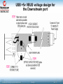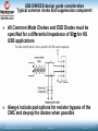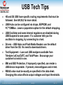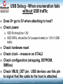
1
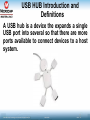
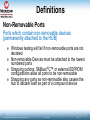
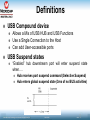
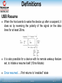
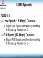
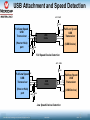
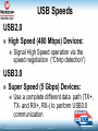
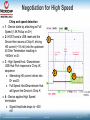
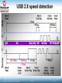
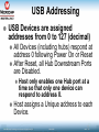
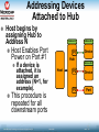
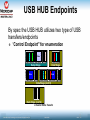
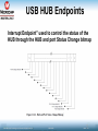
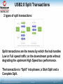
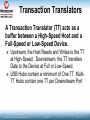
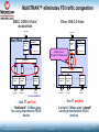
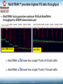
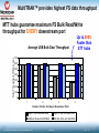
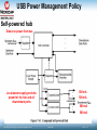
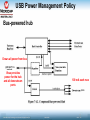
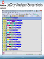
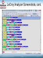
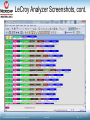
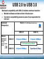
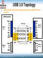
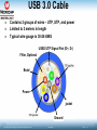
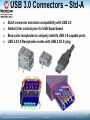
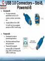
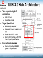
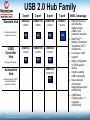
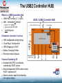
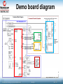
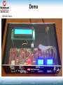
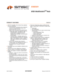
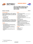
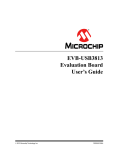
17059 USB6 USB Hub Training © 2013 Microchip Technology Incorporated. All Rights Reserved. 17059 USB6 Slide 1 Airport HUB © 2013 Microchip Technology Incorporated. All Rights Reserved. 17059 USB6 Slide 2 Agenda USB HUB Introduction and Definitions USB Speeds and Hub Transaction Translators Different power consumptions allowed on USB HUB Technical design consideration and debugging USB 3.0 HUB Microchip USB Hub offering © 2013 Microchip Technology Incorporated. All Rights Reserved. 17059 USB6 Slide 3 USB HUB Introduction and Definitions A USB hub is a device the expands a single USB port into several so that there are more ports available to connect devices to a host system. © 2013 Microchip Technology Incorporated. All Rights Reserved. 17059 USB6 Slide 4 Definitions Upstream Port – The port a USB Hub that faces the USB Host Downstream Ports – The Ports on the USB Hub that faces the USB devices – Powered by a power supply that connects directly to the USB device or Hub. Self-Powered Bus-Powered – Powered by the USB Connector VBUS pin. Configured/Unconfigured – A USB device is Unconfigured at first connection until the Host has assigned an address and enabled it. After this point the device is considered to be Configured © 2013 Microchip Technology Incorporated. All Rights Reserved. 17059 USB6 Slide 5 Definitions Non-Removable Ports Ports which contain non-removable devices (permanently attached to the HUB) Windows testing will fail if non-removable ports are not declared Non-removable Devices must be attached to the lowest numbered ports Strapping options, SMBus/I2C™ or external EEPROM configurations allow all ports to be non-removable Strapping any ports as non-removable also causes the hub to declare itself as part of a compound device © 2013 Microchip Technology Incorporated. All Rights Reserved. 17059 USB6 Slide 6 Definitions USB Compound device Allows a Mix of USB HUB and USB Functions Use a Single Connection to the Host Can add User-accessible ports USB Suspend states “Enabled” hub downstream port will enter suspend state when…. Hub receives port suspend command (Selective Suspend) Hub enters global suspend state (3ms of no BUS activities) © 2013 Microchip Technology Incorporated. All Rights Reserved. 17059 USB6 Slide 7 Definitions USB Resume When the host wants to wake the device up after a suspend, it does so by reversing the polarity of the signal on the data lines for at least 20ms. It is also possible for a device with its remote wakeup feature set, to initiate a resume itself (15ms Kstate) Once resumed .…Port returns to “enabled” state © 2013 Microchip Technology Incorporated. All Rights Reserved. 17059 USB6 Slide 8 USB Speeds USB1.1 Low Speed (1.5 Mbps) Devices: Signal Low Speed operation by enabling 1.5K pull-up Resistor on D- Full Speed (12 Mbps) Devices: Signal Full Speed operation by enabling 1.5K pull-up Resistor on D+ © 2013 Microchip Technology Incorporated. All Rights Reserved. 17059 USB6 Slide 9 USB Attachment and Speed Detection +2.7- 3.6V 1.5K Full/Low Speed USB Transceiver 5V D+ D- (Host or Hub) port GND 15K D+ USB Cable Full/Low Speed USB Transceiver D- (USB Device) 15K Full Speed Device Detection +2.7- 3.6V 1.5K Full/Low Speed USB Transceiver 5V D+ USB Cable D- (Host or Hub) port GND 15K D+ Full/Low Speed USB Transceiver D- (USB Device) 15K Low Speed Device Detection © 2013 Microchip Technology Incorporated. All Rights Reserved. 17059 USB6 Slide 10 USB Speeds USB2.0 High Speed (480 Mbps) Devices: Signal High Speed operation via the speed negotiation (“Chirp detection”) USB3.0 Super Speed (5 Gbps) Devices: Use a complete different data path (TX+, TX- and RX+, RX-) to perform USB3.0 communication © 2013 Microchip Technology Incorporated. All Rights Reserved. 17059 USB6 Slide 11 USB Speeds © 2013 Microchip Technology Incorporated. All Rights Reserved. 17059 USB6 Slide 12 Negotiation for High Speed Chirp and speed detection 1 - Device starts by attaching as Full Speed (1.5K Pullup on D+) 2- HOST send a USB reset and the Device then issues a Chirp K, driving HS current (~18 mA) into the upstream 45 Ohm Termination resulting in ~800mV on D3 - High Speed Host / Downstream USB Hub Port response is Chirp JK sequence Alternating HS current driven into D+ and D Full Speed Host/Downstream Hub will Ignore the Device’s Chirp K 4 - Device applies High Speed termination Signal Amplitude drops to ~400 mV © 2013 Microchip Technology Incorporated. All Rights Reserved. 1 2 17059 USB6 3 4 Slide 13 USB 2.0 speed detection © 2013 Microchip Technology Incorporated. All Rights Reserved. 17059 USB6 Slide 14 USB Addressing USB Devices are assigned addresses from 0 to 127 (decimal) All Devices (including hubs) respond at address 0 following Power On or Reset After Reset, all Hub Downstream Ports are Disabled. Host only enables one Hub port at a time so that only one device can respond to address 0. Host assigns a Unique address to each Device. © 2013 Microchip Technology Incorporated. All Rights Reserved. 17059 USB6 Slide 15 Addressing Devices Attached to Hub Host begins by assigning Hub to Address N Host Enables Port Power on Port #1 Address Address N 0 P1 Hub If a device is attached, it is assigned an address (N+1, for example). Address AddressN+1 0 Device Address AddressN+2 0 Host P2 Device P3 Port This procedure is repeated for all downstream ports © 2013 Microchip Technology Incorporated. All Rights Reserved. 17059 USB6 Slide 16 USB HUB Endpoints By spec the USB HUB utilizes two type of USB transfers/endpoints “Control Endpoint” for enumeration S Y N C S E T U P A D D R EC NR DC P5 Token Packet S Y N C D C A R T Data C A 1 0 6 Data Packet S Y N C S YO NU CT A C C K K H/S Pkt D C A R T Data C A 1 1 6 Data Packet S YC NK C S YO NU CT H/S Pkt Data Stage A D D R EC NR DC P5 Token Packet D C A R T Data C A 1 0 6 S Y N C Data Packet Data Stage (cont'd) SD A T A 1 EC NR DC P5 Token Packet Setup Stage S Y N C A D D R SA YC NK C H/S Pkt C R C 1 6 Data Stage (cont'd) A Control Write Transfer © 2013 Microchip Technology Incorporated. All Rights Reserved. 17059 USB6 Slide 17 USB HUB Endpoints Interrupt Endpoint” used to control the status of the HUB through the HUB and port Status Change bitmap © 2013 Microchip Technology Incorporated. All Rights Reserved. 17059 USB6 Slide 18 USB transactions USB 2.0 is designed to allow data communication at 480Mbps while maintaining compatibility to USB1.1 12 Mbps © 2013 Microchip Technology Incorporated. All Rights Reserved. 17059 USB6 Slide 19 USB2.0 Split Transactions 2 types of split transactions: Split transactions are the means by which the hub handles Low or Full speed traffic on the downstream ports without degrading the upstream High Speed bus performance. The transaction is “Split” into phases; a Start Split and a Complete Split. © 2013 Microchip Technology Incorporated. All Rights Reserved. 17059 USB6 Slide 20 Transaction Translators A Transaction Translator (TT) acts as a buffer between a High-Speed Host and a Full-Speed or Low-Speed Device. Upstream, the Host Reads and Writes to the TT at High-Speed. Downstream, the TT transfers Data to the Device at Full or Low-Speed. USB Hubs contain a minimum of One TT. MultiTT Hubs contain one TT per Downstream Port © 2013 Microchip Technology Incorporated. All Rights Reserved. 17059 USB6 Slide 21 MultiTRAK™ eliminates FS traffic congestion SMSC USB2.0 Hubs* Other USB 2.0 Hubs With MultiTRAK To HS Host MultiTRAK Upstream PHY To HS Host Speed Key: SIE Upstream PHY 480 Mbps Path 12 Mbps Path SIE Choke point Single TT Bottleneck Hub Repeater TT TT Downstream PHY #1 Downstream PHY #2 To FS Peripheral To FS Peripheral 480 Mbps Path 12 Mbps Path TT .... .... Speed Key: TT Routing Logic Downstream PHY #1 Downstream PHY # N .... Downstream PHY #2 To FS Peripheral To FS Peripheral To FS Peripheral .... .... Downstream PHY #4 To FS Peripheral * Exclude USB2502 One TT per Port “Dedicated” 12 Mbps pipe for every downstream FS/LS device © 2013 Microchip Technology Incorporated. All Rights Reserved. One TT per Hub A single 12 Mbps pipe “shared” among 4 downstream FS/LS devices 17059 USB6 Slide 22 MultiTRAK™ provides highest FS data throughput MultiTRAK hubs guarantee maximum FS Bulk Read/Write throughput for EVERY downstream port 1 port 2 ports 3 ports 4 ports 5 ports 6 ports 7 ports 1 port 2 ports 3 ports 4 ports 5 ports KB/s 6 ports 7 ports KB/s Other USB2.0 hubs MultiTRAK MultiTRAK is 2x faster than single-TT with 4 FS bulk traffic MultiTRAK is 3x faster than single-TT with 7 FS bulk traffic © 2013 Microchip Technology Incorporated. All Rights Reserved. 17059 USB6 Slide 23 MultiTRAK™ provides highest FS data throughput MTT hubs guarantee maximum FS Bulk Read/Write throughput for EVERY downstream port Up to 200% Faster than STT hubs Data Throughput (KB per sec) Average USB Bulk Data Throughput 700 600 500 400 300 200 100 0 1 2 3 4 Number of Active Full-Speed Downstream Ports Single-TT hub USB Bluk Read Single-TT Hub USB Bulk Write USB Bulk Read with MultiTRAK USB Bulk Write with MultiTRAK © 2013 Microchip Technology Incorporated. All Rights Reserved. 17059 USB6 Slide 24 Power Considerations Bus Powered HUB Unconfigured: (Total) < 100 mA Configured: < 500 mA HUB Current + 100mA * (# of DP) Downstream Ports can not support 500 mA 2 USB Bus Powered HUB in cascade are not allowed by spec Self Powered (Total) < 100 mA © 2013 Microchip Technology Incorporated. All Rights Reserved. 17059 USB6 Slide 25 USB Power Management Policy Self-powered hub Draws no power from bus 500 mA Local power supply provides power for the hub and all downstream ports 500 mA 500 mA 500 mA © 2013 Microchip Technology Incorporated. All Rights Reserved. 17059 USB6 Slide 26 USB Power Management Policy Bus-powered hub Draws all power from bus Vbus provides power for the hub and all downstream ports © 2013 Microchip Technology Incorporated. All Rights Reserved. 100 mA each max 17059 USB6 Slide 27 The Changing USB Universe The USB Eco system continues to increase in capability’s in both Speed and Power Faster speeds 1.5Mbs, 12Mbs, 480Mbs, 5Gbs Higher power – 500ma, 900ma, 1500ma, 100W Battery Charging standards evolve constantly with both vendor specific and standards based solutions Power Delivery is coming soon – 2013! USB-IF specifications - BC1.1, BC1.2, Apple (L/M/H), RIM (Blackberry) “defacto standards” China and Europe have adopted countrywide standards USB Battery charging (17058 USB5) class available at the MCHP Master The USB-IF compliance tests continually evolve Mobile devices are changing the landscape © 2013 Microchip Technology Incorporated. All Rights Reserved. 17059 USB6 Slide 28 USB VBUS Progression VBUS Voltage Range 20.0V 100 W USB Power Delivery Revolutionizes the VBUS Pin Any voltage from 0 to 20V 12.0V Any current from 0 to 5A 5.5V 4.5V USB 2.0 USB 3.0 0.5A BC 1.2 0.9A 1.5A 5.0A VBUS Current Range VBUS Can Now Provide Up To 100W of Power © 2013 Microchip Technology Incorporated. All Rights Reserved. 17059 USB6 Slide 29 Important features to consider when choosing USB HUB © 2013 Microchip Technology Incorporated. All Rights Reserved. 17059 USB6 Slide 30 PortMap PortMap provides flexible port mapping and disable sequence For any port that is disabled, USB251x automatically reorder the remaining ports to match the USB host controller’s port numbering scheme Logical Connection P1: P2: P3: P4: Connected Connected Disabled Disabled Physical Connection P0 P1 P2 P3 P4 Disabled Connected Disabled Connected USB port virtualization 7/31/2013 © 2013 Microchip Technology Incorporated. All Rights Reserved. 17059 USB6 Slide 31 PortSwap PortSwap adds per-port programmability to USB differential-pair pin location and allows direct alignment of USB signals (D+/D-) to connectors thus avoiding uneven trance length or crossing of the USB differential signals on the PCB USB Connector D+ D- DD+ USB Connector DD+ DD+ 7/31/2013 © 2013 Microchip Technology Incorporated. All Rights Reserved. 17059 USB6 Slide 32 PHYBoost PHYBoost enables four-level programmable USB signal drive strengths (0%, +4%, +8%, +12%) in downstream port transceivers. PHYBoost attempts to restore USB signal integrity that has been compromised by system level variables such as poor PCB layout, analog switches, long cables, etc. PHYBoost “opens up” the eye and restores signal integrity 8% 4%Boost Boost 12% Boost 7/31/2013 Eye diagram compromised system environment © 2013 Microchip Technology Incorporated. All Rights Reserved. 17059 USB6 Slide 33 USB 2.0 Hub HW design consideration © 2013 Microchip Technology Incorporated. All Rights Reserved. 17059 USB6 Slide 34 Power Decoupling caps SMSC USB Hubs contain 2 integrated LDO Regulators External Low ESR (<200mW) Caps are Required © 2013 Microchip Technology Incorporated. All Rights Reserved. 17059 USB6 Slide 35 Add the Voltage drop budgeting (Self Power Hub ) The voltage seen at the port must be between 5.25 and 4.75V © 2013 Microchip Technology Incorporated. All Rights Reserved. 17059 USB6 Slide 36 USB +5v VBUS voltage design for the Downstream port © 2013 Microchip Technology Incorporated. All Rights Reserved. 17059 USB6 Slide 37 USB EMI/ESD design guide consideration Typical common choke and suppression component All Common Mode Chokes and ESD Diodes must be specified for a differential impedance of 90W for HS USB applications Always include pad options for resistor bypass of the CMC and de-pop the diodes when possible © 2013 Microchip Technology Incorporated. All Rights Reserved. 17059 USB6 Slide 38 USB Tech Tips HS and SS USB have specific routing requirements that must be followed. See AN 26.2 for more detail. USB Hubs can be configured via straps, EEPROM, and I2C™/SMBus. Leave a population option for the default strapping. USB Oscillator and some internal regulators are disabled during USB Suspend to save power. If a customer tells you the oscillator is stopping, try connecting to a host. Drivers – USB Hubs and Flash Media Readers use the default driver from the OS. No need to download drivers. Test Equipment – Low cost USB analyzers available from Teledyne LeCroy/CATC and TotalPhase. Encourage your customer to invest in one. EMI and ESD Protection, if improperly specified, can render a USB device inoperable. If present, remove/bypass and re-test. RBIAS value must be exactly as specified in the data sheet. Changing this value affects output voltages and input thresholds. © 2013 Microchip Technology Incorporated. All Rights Reserved. 17059 USB6 Slide 39 USB Debug - When enumeration fails without USB traffic Does D+ go to 3V when attaching to host? Check power VDD18 should be 1.8V VDD18PLL should be 0V (suspend state) or 1.8V if USB traffic Check hardware reset Check clock – measure on XTAL2 Check configuration (strapping, EEPROM, SMBus) Check VBUS_DET pin. USB devices use this pin to signal that the cable to the host is attached. © 2013 Microchip Technology Incorporated. All Rights Reserved. 17059 USB6 Slide 40 USB Debug - When enumeration fails with USB traffic Full-speed High-speed Check that USB Reset is generated Check that SOFs starts less than 3 mS after end of USB Reset Check that USB Reset is generated Check that chirping occurred Check that SOFs starts less than 3 mS after end of USB Reset Collect CATC trace Check descriptor data returned (configuration) Check for errors (timeouts or CRC) © 2013 Microchip Technology Incorporated. All Rights Reserved. 17059 USB6 Slide 41 USB 2.0 CATC bus analyzer application © 2013 Microchip Technology Incorporated. All Rights Reserved. 17059 USB6 Slide 42 CATC bus analyzer © 2013 Microchip Technology Incorporated. All Rights Reserved. 17059 USB6 Slide 43 CATC bus analyzer connection © 2013 Microchip Technology Incorporated. All Rights Reserved. 17059 USB6 Slide 44 LeCroy Analyzer Screenshots © 2013 Microchip Technology Incorporated. All Rights Reserved. 17059 USB6 Slide 45 LeCroy Analyzer Screenshots, cont. © 2013 Microchip Technology Incorporated. All Rights Reserved. 17059 USB6 Slide 46 LeCroy Analyzer Screenshots, cont. © 2013 Microchip Technology Incorporated. All Rights Reserved. 17059 USB6 Slide 47 USB3.0 HUB © 2013 Microchip Technology Incorporated. All Rights Reserved. 17059 USB6 Slide 48 USB 2.0 to USB 3.0 Backward compatibility with USB 2.0 enables seamless transition Maintain software and device driver infrastructure Connector compatibility preserves ease-of-use expectation for end user End User Perspective Host (PC, TV, STB, Game Console, etc.) USB 2.0 USB 3.0 Hi-Speed (480Mbps) Hi-Speed (480Mbps) Device (KB, Mouse, Flash Drive, Printer, Camera, Hard Drive) USB 2.0 All Combinations Work! USB 3.0 © 2013 Microchip Technology Incorporated. All Rights Reserved. Hi-Speed (480Mbps) 17059 USB6 SuperSpeed (5Gbps) Slide 49 USB 3.0 Topology USB 3.0 adds a PCIe-like data pipe and preserves USB 2.0 2-wire interface USB Host/Hub USB 3.0 Port USB 2.0 Port Vbus D+ DTX+ TXRX+ RXGND Vbus D+ DGND USB Cable Vbus D+ DTX+ TXRX+ RXGND © 2013 Microchip Technology Incorporated. All Rights Reserved. Vbus D+ DTX+ TXRX+ RXGND 17059 USB6 Vbus D+ D- USB 3.0 Device TX+ TXRX+ RXGND Vbus USB 2.0 D+ Device DGND Slide 50 USB 3.0 Cable Contains 3 groups of wires – UTP, STP, and power Limited to 3 meters in length Typical wire gauge is 30-26 AWG USB2 UTP Signal Pair (D+, D-) Filler, Optional Braid Power jacket Ground © 2013 Microchip Technology Incorporated. All Rights Reserved. 17059 USB6 Slide 51 USB 3.0 Connectors – Std-A Std-A connector maintains compatibility with USB 2.0 Added 2-tier contact pins for USB SuperSpeed Blue-color receptacles to uniquely identify USB 3.0-capable ports USB 2.0/3.0 Receptacles mates with USB 2.0/3.0 plug USB3 RX GND GND USB3 TX USB3 TX © 2013 Microchip Technology Incorporated. All Rights Reserved. 17059 USB6 Slide 52 USB 3.0 Connectors – Std-B, Powered-B Standard-B For large stationary peripherals such as LCD monitor, printers, hard drives, etc. Visually different from USB 2.0 std-B, but the receptacle accepts a USB 2.0 std-B plug Powered-B Developed for devicepowered applications Std-B plus additional Power and ground pins Powered-B receptacle accepts USB 3.0 Powered-B plug, USB 3.0 Std-B plug and USB 2.0 std-B plug © 2013 Microchip Technology Incorporated. All Rights Reserved. 17059 USB6 Slide 53 USB 3.0 Hub Architecture Two separate logical controllers SuperSpeed hub USB 2.0 hub SuperSpeed hub Not a simple repeater Store and forward headers and data Works like a PCIe switch Connects to host as both USB 2 and SuperSpeed Device Downstream devices Connect at either USB 2.0 speed or SuperSpeed © 2013 Microchip Technology Incorporated. All Rights Reserved. 17059 USB6 Slide 54 Microchip USB HUB offering © 2013 Microchip Technology Incorporated. All Rights Reserved. 17059 USB6 Slide 55 USB 2.0 Hub Family Standard Hub Full-featured USB port expansion solutions 2-port 3-port 4-port 7-port USB2422 USB2513B USB2514B USB2517 36 QFN 36QFN 36 QFN 64 QFN 4x4 6x6 6x6 9x9 SMSC Advantage USB2 Controller Hub USB2532 USB2513B USB2534 36 QFN 36 QFN 36 QFN 6x6 6x6 6x6 Next-gen USB2 hubs Automotive Hub Automotive-grade (PPAP complete) USB port expansion solutions USB82514 36/56 QFN 6x6 © 2013 Microchip Technology Incorporated. All Rights Reserved. 17059 USB6 High performance, cost effective, market-proven USB2.0 port expansion solutions MultiTRAK™ Multiple Transaction Translators (MTT) Architecture Low power, small footprint Highly configurable for OEM specific options Industry-leading USB compatibility New extended commercial temperature support (USB251xB) USB Battery Charging spec 1.1 compliant (USB251xB) Slide 56 The USB2 Controller HUB What is a USB Controller Hub USB HUB Function (2, 3, 4 port) With – Embedded Controller UCH2 = USB2 Controller HUB GPIO, I2C™, SMbus, Can execute from SPI flash And End point Embedded Controller Functions HUB configuration during startup “Quad Page” Configuration GPIO Bridging for HOST Battery Charging Profiles Executes custom features Features Enabled by EC Enables HUB GPIO to be directly controlled by HOST system Allows independent HUB functions while HOST is powered off Allows customer specific functionality into system design © 2013 Microchip Technology Incorporated. All Rights Reserved. 17059 USB6 Slide 57 New USB Hub Controller SKUs USB2 Hub Upstream Downstream Package Applications USB2532-1080AEN USB USB x2 36 QFN Hub Controller – 2 Port USB2533-1080AEN USB USB x3 36 QFN Hub Controller – 3 Port USB2534-1080AEN USB USB x4 36 QFN Hub Controller – 4 Port USB4624-1080HN HSIC/USB USB x2 / HSIC x2 48 QFN Hub Controller with USB & HSIC USB4604-1080HN HSIC/USB USB x4 48 QFN Hub Controller with USB & HSIC USB3813-1080XY USB USB x2 / HSIC x1 30 WLCSP Mobile Hub Controller USB3613-1080XY HSIC USB x2 / HSIC x1 30 WLCSP Mobile Low-Power Hub Controller Naming structure • USB46YX - HSIC upstream, X - # of ports, Y - # of HSIC ports, 48P QFN • USB38YX - USB upstream, X - # of ports, Y - # of HSIC ports, 30P WLCSP • USB36YX - HSIC upstream, X - # of ports, Y - # of HSIC ports, 30P WLCSP • USB253x- USB upstream, x=number of downstream USB ports, 36P QFN © 2013 Microchip Technology Incorporated. All Rights Reserved. 17059 USB6 Slide 58 USB3.0 HUB options USB5537B – Seven Port “Hybrid Hub” USB5534B – Four Port Hub USB5533B – Three Port Hub USB5532B – Two Port Hub Industry’s Most Complete Hub Product Line © 2013 Microchip Technology Incorporated. All Rights Reserved. 17059 USB6 Slide 59 USB3.0 HUB feature comparison Features USB5532B USB5533B USB5534B USB5537B 2 3 4 7 64QFN 64QFN 64QFN 72QFN MultiTRAK™ PortMap, PortSwap, TruSpeed, PHYBoost Vendor Specific Messaging (VSM) Custom configuration with SPI, SMB Std Commercial Temp (0 to 70C) Industrial Temp (-40 to 85C) BC1.2 & Apple Charging Support the USC1002 (Advanced Power Management ) Designed for 2-Layer PCBs # of Downstream Ports Package © 2013 Microchip Technology Incorporated. All Rights Reserved. 17059 USB6 Slide 60 Where to Find More Information USB2.0 and USB3.0 Specifications USB Complete book by Jan Axelson USB Made Simple, a series of articles on USB http://www.usb.org/developers/docs/ Chapter 11 for USB HUB in USB2.0 spec http://www.usbmadesimple.co.uk/ Microchip USB HUBs Data Sheets and Application Notes http://www.smsc.com/Products/USB/USB_Hubs © 2013 Microchip Technology Incorporated. All Rights Reserved. 17059 USB6 Slide 61 Summary USB2.0 and USB3.0 have become most ubiquitous interfaces in commercial and embedded applications USB HUB is one of the most important elements in the USB topology Power consumption is very critical when designing with HUBs Signals integrity and protocol compliance are key factors, especially to obtain the USB Logos Microchip has the largest and most features rich family of USB HUBs © 2013 Microchip Technology Incorporated. All Rights Reserved. 17059 USB6 Slide 62 Demo board diagram © 2013 Microchip Technology Incorporated. All Rights Reserved. 17059 USB6 Slide 63 Demo USB46XX Demo © 2013 Microchip Technology Incorporated. All Rights Reserved. 17059 USB6 Slide 64 LEGAL NOTICE SOFTWARE: You may use Microchip software exclusively with Microchip products. Further, use of Microchip software is subject to the copyright notices, disclaimers, and any license terms accompanying such software, whether set forth at the install of each program or posted in a header or text file. Notwithstanding the above, certain components of software offered by Microchip and 3 rd parties may be covered by “open source” software licenses – which include licenses that require that the distributor make the software available in source code format. To the extent required by such open source software licenses, the terms of such license will govern. NOTICE & DISCLAIMER: These materials and accompanying information (including, for example, any software, and references to 3 rd party companies and 3rd party websites) are for informational purposes only and provided “AS IS.” Microchip assumes no responsibility for statements made by 3 rd party companies, or materials or information that such 3 rd parties may provide. MICROCHIP DISCLAIMS ALL WARRANTIES, WHETHER EXPRESS, IMPLIED, OR STATUTORY, INCLUDING ANY IMPLIED WARRANTIES OF NONINFRINGEMENT, MERCHANTABILITY, AND FITNESS FOR A PARTICULAR PURPOSE. IN NO EVENT WILL MICROCHIP BE LIABLE FOR ANY DIRECT OR INDIRECT, SPECIAL, PUNITIVE, INCIDENTAL, OR CONSEQUENTIAL LOSS, DAMAGE, COST, OR EXPENSE OF ANY KIND RELATED TO THESE MATERIALS OR ACCOMPANYING INFORMATION PROVIDED TO YOU BY MICROCHIP OR OTHER THIRD PARTIES, EVEN IF MICROCHIP HAS BEEN ADVISED OF THE POSSIBLITY OF SUCH DAMAGES OR THE DAMAGES ARE FORESEEABLE. TRADEMARKS: The Microchip name and logo, the Microchip logo, dsPIC, FlashFlex, K EELOQ, KEELOQ logo, MPLAB, PIC, PICmicro, PICSTART, PIC32 logo, rfPIC, SST, SST Logo, SuperFlash and UNI/O are registered trademarks of Microchip Technology Incorporated in the U.S.A. and other countries. FilterLab, Hampshire, HI-TECH C, Linear Active Thermistor, MTP, SEEVAL and The Embedded Control Solutions Company are registered trademarks of Microchip Technology Incorporated in the U.S.A. Silicon Storage Technology is a registered trademark of Microchip Technology Inc. in other countries. Analog-for-the-Digital Age, Application Maestro, BodyCom, chipKIT, chipKIT logo, CodeGuard, dsPICDEM, dsPICDEM.net, dsPICworks, dsSPEAK, ECAN, ECONOMONITOR, FanSense, HI-TIDE, In-Circuit Serial Programming, ICSP, Mindi, MiWi, MPASM, MPF, MPLAB Certified logo, MPLIB, MPLINK, mTouch, Omniscient Code Generation, PICC, PICC-18, PICDEM, PICDEM.net, PICkit, PICtail, REAL ICE, rfLAB, Select Mode, SQI, Serial Quad I/O, Total Endurance, TSHARC, UniWinDriver, WiperLock, ZENA and Z-Scale are trademarks of Microchip Technology Incorporated in the U.S.A. and other countries. SQTP is a service mark of Microchip Technology Incorporated in the U.S.A. GestIC and ULPP are registered trademarks of Microchip Technology Germany II GmbH & Co. KG, a subsidiary of Microchip Technology Inc., in other countries. All other trademarks mentioned herein are property of their respective companies. © 2013 Microchip Technology Incorporated. All Rights Reserved. 17059 USB6 Slide 65