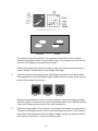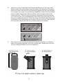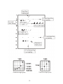
1
405 GSX LE Precision Resolution Grey Scale Phantom User’s Guide Table of Contents Introduction...............................................................................................................................3 Caring for your 405 GSX LE....................................................................................................4 Scanning your 405 GSX LE....................................................................................................5 A Guided Tour of your 405 GSX LE...........................................................................................6 Evaluating the Phantom...........................................................................................................7 Target Specifications..........................................................................................................12 Cystic Targets....................................................................................................................12 Grey Scale Targets..................................................................................................................12 Pin Targets............................................................................................................................12 Resolution Target Group.......................................................................................................12 Phantom Specifications......................................................................................................14 Physical Specifications.......................................................................................................14 Tissue Mimicking Background Material................................................................................14 Harmonic Imaging.................................................................................................................15 Grey Scale Applications...........................................................................................................16 System Linearity.................................................................................................................17 Quantitative Measurement.................................................................................................19 Baseline Test.....................................................................................................................19 Subsequent Tests..................................................................................................................19 Qualitative Measurement....................................................................................................21 Phantom Desiccation.........................................................................................................22 Charts and Graphs..............................................................................................................22 Product Warranty...............................................................................................................23 Sales and Service...............................................................................................................24 2 Introduction The 405 GSX LE phantom provides users with a wide range of criteria to evaluate the performance of their ultrasound machine. The advanced tissue mimicking gel used in the phantom has been developed to provide a smoother background texture than conventional gels. The gel reduces backscatter and is fully compatible with the latest tissue harmonics equipment and technology. The phantom utilizes an advance composite film scanning surface that improves transmission properties, thus allowing more of the ultrasound beam to be received and transmitted. The 405 GSX LE phantom is designed to be used for quality control purposes when monitoring these important image characteristics: 1. 2. 3. 4. 5. axial resolution lateral resolution dead zone target imaging vertical and horizontal distance accuracy image uniformity The triangular grey scale targets in the phantom can be used to test the resolution of high performance ultrasound scanners. Unique to the 405 GSX LE are two horizontal cross fibers located in the middle of the phantom. These fibers have been included to assist the user in aligning the transducer and can be used as a reference “marker” to ensure that QA tests are performed consistently every time. Limitations of Use The 405 GSX LE is designed to be used to aid in the quality control testing and monitoring of high performance ultrasound systems only. It is not to be used to make diagnostic decisions. 3 Caring for your 405 GSX LE Phantom comes ready to scan. Do not remove surface material. Store your 405 GSX LE with cover closed securely. Always attach the scanning surface cover and store the phantom out of direct sunlight when it is not in use. Store your 405 GSX LE at 35º–105ºF (2º–40ºC). Freezing temperatures will damage the phantom and high temperatures will accelerate desiccation. Weigh your 405 GSX LE to monitor desiccation. Weigh the phantom when you first receive it and then every 6 months. Record the values on the data sheet. Do not drop or damage the phantom. Return the phantom for inspection and/or repair if it has been dropped or damaged. Physical damage to the case will cause premature desiccation. Gammex recommends annual servicing of your 405 GSX LE to ensure proper operation. Our qualified service technicians will check for desiccation and provide any needed rejuvenation, scanning/certification to original specifications, and repairs. 4 Scanning your 405 GSX LE • Always place the phantom on a stable, level surface for scanning. • The phantom comes ready to scan. Do not peel off the surface material. • Use water or a generous amount of coupling gel to ensure good transmission. Do not use mineral oil, baby oil or lanolin-based gels as a coupling medium. Poor transmission is a result of insufficient coupling. • Do not press the transducer into the scanning surface. This damages the scanning surface and will shorten the life of the phantom. For curved transducers, use water or a thick gel layer. • Clean the scanning surface immediately after use. Use a soft cloth or paper towel and soap and water, if needed. Caution: Do not press the transducer into the scanning surface. 5 A Guided Tour of your 405 GSX LE The Precision Resolution Grey Scale Phantom, 405 GSX LE, provides a means for monitoring the image quality of ultrasound scanning systems. The tissue mimicking gel in the 405 GSX LE is ultrasonically similar to human tissue. This allows the use of normal scanner control settings and ensures that the performance measured, closely approximates the scanner’s performance in a clinical examination. Scanning is the best way to familiarize yourself with the features and functions of the 405 GSX LE. A guided tour is provided on the following pages. 6 Evaluating the Phantom Remember • The phantom comes ready to scan. Do not peel off surface material. • Never press the transducer into the scanning surface. • Always clean and dry the scanning surface after each use. Never leave coupling gel or water on the scanning surface for more than a few hours. • Do not use mineral oil, baby oil, or lanolin-based gels as a coupling medium. A 4.5 MHz probe will provide a good overall view of the phantom for this demonstration. 1. Turn the handle out of the way and slide the cover off the phantom. 2. To couple with water, fill the dam with distilled water. For a better image quality, use gel. 3. Rest the transducer on the scanning surface. Adjust the scanner to display the full depth of the phantom. You may notice that the tissue echoes near the bottom of the phantom fade into noise. The depth at which usable echoes disappear is called the depth of penetration. The depth markers on the phantom label will help you determine the depths of the targets. 7 4. Move the transducer across the scanning surface while observing the locations of the targets. Notice how the smooth texture of the tissue mimicking gel emphasizes image non-uniformities and artifacts, making them easier to detect. Scanning an area without targets is a good way to test for image uniformity. Decrease gain controls to highlight pin targets. 5. Scan the vertical pin targets and freeze the image. Use the electronic calipers to measure the distance between two of the vertical pin targets. Repeat for two of the horizontal pin targets. The vertical pins have 2 cm spacing while the horizontal pins have 3 cm spacing. Use these pin targets to determine vertical distance accuracy and horizontal distance accuracy. Note that the highest dead zone pin you can see should be the point of reference not the scanning surface. 6. Freeze an image of the resolution target group at 1 cm. Examine the horizontal row of pins at the top of the target group. The pins that are closest together without touching indicates the scanner’s lateral resolution. Repeat this procedure with the other resolution target groups. Notice how lateral resolution is narrowest in the focal zone. For a transducer whose focal zone is in the area between the resolution targets, an alternate test can be performed. 8 Freeze an image of the vertical pin targets. Use the electronic calipers to measure the horizontal width of the pin targets in the near, mid and far fields of the image. Notice how the pin targets are narrowest in the focal zone. The pin width demonstrates the width of the ultrasound beam at that depth and approximates the lateral resolution of the scanner. 7. Decrease the image depth and examine the axial resolution target group at 3 cm. Notice how the images of the lower pin targets may begin to merge. The smallest distance between two pins that can be clearly resolved with no vertical overlap is called the scanner’s axial resolution. 9 Unresolved Resolved Pin targets are resolved axially if an imaginary horizontal line can be drawn between the targets without touching either target. The targets on the left are not resolved. The targets on the right are resolved. Examine the other axial resolution target groups and compare the resolution at various depths. Axial resolution may change with depth. 8. Scan the nearest cystic target group. Each target should be round with a clean black appearance and well defined edges. Bright specular echoes at the top and bottom of the targets are normal. Measure the dimensions of the 6 mm cystic target to check the image geometry. Use the calipers to measure from top to bottom and side to side. Repeat with the other cystic target groups as part of the cyst imaging test. 9. Decrease image depth to the minimum and examine the dead zone target group. The dead zone targets can be used to measure lateral resolution in the extreme near field of the transducer. Note the highest dead zone pin you can see should be the point of reference - Not the scanning surface. 10 10. Scan the four grey scale targets and observe the difference in their grey levels. Adjust the gain control and observe how this affects the brightness of the targets. Notice how noise in the anechoic target becomes apparent as the gain increases. If your system has image “post-processing” capabilities, observe how the contrast between targets changes with different settings. Adjust the gain control to the lowest noise level. This is the point at which you eliminate noise in the anechoic cyst (lower the gain until it just disappears). Record this gain setting and use it for future grey scale measurements. Freeze the image and visually evaluate the grey scale targets. Match each target with a step on the grey bar in the image. Make a hard copy and compare the hard copy with the image on the scanner. low scatter -6 dB 1 2 +6 dB high scatter 3 4 Noise in low scatter cyst 11. When you are done scanning the phantom, empty the water dam or completely clean off the coupling gel with a soft cloth or paper towel. Replace the cover and secure by lifting the handle to protect the phantom. 11 Target Specifications Cystic Targets Diameters.........................................................................................................2, 4, and 6 mm Placement................................................................................................3, 8, and 14 cm deep Speed of sound..................................................................................................1540±10 m/s Attenuation coefficient........................................................................0.05±0.01 dB/cm/MHz Grey Scale Targets Dimensions................................................................................................9.5 x 9.5 x 13.4 mm Placement..............................................................................................................4 cm deep Speed of sound..................................................................................................1540±10 m/s Temperature dependence on speed of sound...........................................................1.5 m/s/ºC Contrast ..................................low scatter, -6 dB, +6 dB, high scatter relative to background Pin Targets Diameter....................................................................................................................0.1 mm Vertical spacing..................................................................................... 2 cm at 2–16 cm deep Horizontal spacing..........................................................................3 cm at 2 and 12 cm deep Cross fibers...............................................................................0.2 mm at 2 and 6 cm deep Resolution Target Group .................................................................................................at 3, 8, and 14 cm deep All acoustic measurements made at 4.5 MHz, 22ºC. Due to our philosophy of continuous quality improvement, all specifications are subject to change. 12 13 . Phantom Specifications Physical Specifications Weight................................................................................................ Approx. 2.8 kg (6 lbs. 5 oz.) Dimensions................................................................................................. 23.2 x 8.25 x 18.5 cm ..........................................................................................................(9.25 x 3.25 x 7.25 in.) Scanning surface..................................................................................................Composite Film Case material................................................................................................Extruded ABS plastic Pin target material........................................................................................Nylon monofilament Tissue Mimicking Background Material Water-based gel with appearance of human tissue. Speed of sound............................................................................................................1540±10 m/s Attenuation coefficient..................................................................................0.7±0.05 dB/cm/MHz ...............................................................................................0.5±0.05 dB/cm/MHz ............................................................................... refer to phantom side label Nonlinearity parameter (B/A)............................................................................................ 6.6±0.3 .......................................................6.7 (Accepted value for human liver tissue) All acoustic measurements made at 4.5 MHz, 22ºC. Due to our philosophy of continuous quality improvement, all specifications are subject to change. 14 Harmonic Imaging Harmonic imaging has become an important addition to the medical ultrasound community. Harmonic imaging is when a pulse is sent from the transducer at a nominal (fundamental) frequency, but the signal received by the transducer is twice that frequency, which is the second harmonic. The result is that better resolution is attained at any given depth than if the reception had been at the fundamental frequency, as in conventional ultrasound. There are three tissue properties that determine the effectiveness of harmonic imaging: 1. 2. 3. pulse propagation speed attenuation (rate of pulse energy loss with depth) the value of the nonlinearity parameter: B/A In order for phantoms to present valid resolution results for harmonic imaging, these three properties must adequately correspond to human tissue. Attenuation increases with frequency and much of the propagation involves the fundamental frequency, so in harmonic imaging, there is enhanced resolution without as much attenuation as there would be if the higher frequency were used to generate the pulses at the transducer. So, higher frequency resolution occurs for greater depths within the subject than if conventional ultrasound was used. The ratio of B/A quantifies the rate of transfer with respect to propagation distance of ultrasonic fundamental frequency energy to harmonic frequencies. The greater the amplitude, the greater the energy transfer rate; thus, the beam profile for the harmonic is smaller than for the fundamental, which means better lateral and elevational resolution. Tissue-mimicking phantoms will be appropriate for assessing harmonic imaging only if B/A for the tissue-mimicking material in the phantom adequately approximates that of soft tissues. Recently, we have developed the capacity to measure the value of B/A for the tissue-mimicking materials in Gammex phantoms and have found it to lie in the range for human soft tissue, meaning B/A is between 6 and 71. _____________________________________________ 1 Gong, X. F., Zhu, Z. M., Shi, T., Huang, J. H. (1989) Determination of the acoustic nonlinearity parameter in biological media using FAIS and ITD methods, J. Acoust. Soc. Am. 86 (1), pp 1-5. 15 Grey Scale Applications Metastases are sometimes slightly hyperechoic or hypoechoic compared with the surrounding tissue. If the scanner is not measuring grey levels accurately, the metastases may not be detected. The Quantitative Measurement ensures that the grey level signal is measured consistently. The Qualitative Measurement ensures that grey levels are displayed on the monitor consistently. By performing these tests, the user can determine the optimal system settings for measuring grey levels, which can then be used in clinical applications. 16 System Linearity Ultrasound systems use special processing circuits to translate the amplitude of echoes into brightness levels on the video monitor. These circuits use mathematical functions that often produce an S-shaped curve when graphed. As shown in the figure below, each echo level produces a corresponding brightness level on the monitor. An S-shaped curve is used to translate echo levels into brightness levels on the video display. Notice how each echo level, –X, 0 and +X dB produce the corresponding brightness values B–, Bo and B+. As long as the shape of the curve remains constant, the contrast, or difference in brightness between different echo levels, will remain constant. If the shape of the S-curve changes, the relative image brightness for each echo level will also change. For example, image post-processing techniques help the user identify subtle tissue variations by modifying the shape of the S-curve to emphasize certain ranges of echo levels. Degradation in the system hardware can also affect the shape of the curve and produce unexpected variations in the contrast between echo levels. The distortion in the information displayed to the user may affect the interpretation of the ultrasound image. This is why it is important to do quality measurement with as little post-processing as possible. An example of these distortions is shown on the following page. 17 Changes in the shape of the S-curve result in different brightness levels for the same echo levels. Notice how the positions of the original brightness levels B–, Bo and B+ have moved to B–1, Bo1 and B+1. Changes in the system response can be identified by measuring the average pixel value of the grey scale targets and the background material as displayed on the video monitor. Pixel values can be estimated by eye or measured with image analysis tools provided on some ultrasound instruments or computers equipped with video “frame grabbers” and special software. 18 Quantitative Measurement A target’s brightness level can be most accurately measured using electronic methods. The user defines a region of interest and the scanner determines the average pixel value. To reduce the effect of speckle and small variations in the targets, several measurements are taken and averaged. Note: If your system does not have a region of interest (ROI) tool, you will not be able to perform this test. As an alternative, refer to the Qualitative Measurement section of this document (on page 21). Note: All values determined by the quantitative measurement test depend on scanning technique. Great care should be taken to perform the test in the same manner each time. Method Define a region of interest and measure the average echo level. Procedure Baseline Test 1. Scan the grey scale targets and display them as large as possible. Freeze the image. 2. Measure the echo level of the anechoic target. Adjust the system gain so that the measurement is approximately 1. This ensures that the system’s noise floor is barely reaching the visible level. 3. Record this setting and reuse for all subsequent tests. Subsequent Tests 1. Scan the grey scale targets and display them as large as possible. Adjust the system control settings as recorded on the data sheet. 2. Freeze the image and place the region of interest (ROI) tool completely inside the grey scale target image. The ROI should be approximately 2/3 – 3/4 the diameter of the circle, and it should be centered in the circle. 19 3. Measure and record the echo level of each target. 4. Measure and record the echo level of the background material directly beside the anechoic target. Use as close to the same ROI as the target as possible. Unfreeze the image. 5. Perform this process three times and record the average echo level for each grey scale target and for the background material on the data sheet. Analysis Contact your service engineer if target 2, 3, or 4 varies from the baseline by 10% or more. 20 Qualitative Measurement Video monitors on most ultrasound systems contain a “grey bar” which shows the grey levels available for display. Grey bars normally contain between sixteen and sixty-four steps of increasing brightness. Pixel values can be estimated by locating a grey bar step that approximates the brightness of the region of interest. Note: It is absolutely critical that all system control settings be precisely reproduced for these tests. Errors will introduce variations in your data and potentially invalidate your results. Method Assign a step on the grey bar to each grey scale target and the background. Procedure 1. Assign a unique number to each grey level on the grey bar. 2. Scan the grey scale targets and display them as large as possible. Freeze the image. 3. For each target, determine which step on the grey bar is the same brightness as the target and record this number on the data sheet. Do the same for the background material directly beside the anechoic target. Keep a print out of the image for reference. Analysis Contact your service engineer if any target varies from the baseline by more than two steps. 21 Phantom Desiccation Over time, the phantom’s water-based gel will slowly lose moisture. This process is accelerated by high temperatures, incorrect storage, and damage to the case or scanning surface. Consistently storing the phantom in an air-tight container will contribute greatly to long phantom life. Properly storing your phantom will reduce the amount of moisture lost per year. For instructions on how to properly store and take care of your phantom, go to the Caring for Your Phantom section. For most climate-controlled environments, the phantom weight should be checked every six months. Phantoms used in high temperature/low humidity environments or in mobile situations should be tested more frequently. As the phantom desiccates, the scanning surface may flatten out. It is suggested that the phantom be sent in for rejuvenation once it has lost 10-15 grams of its original weight. If the phantom has lost more than 20 grams, Gammex cannot guarantee that the phantom will be able to rejuvenate successfully. Charts and Graphs Refer to the Charts and Graphs section of the manual CA to find the appropriate charts and graphs for your 405 GSX LE phantom, which include: Data Sheet Quantitative Measurement Qualitative Measurement 22 Product Warranty WARRANTY, DISCLAIMERS AND LIMITATION OF LIABILITY: The Products are covered by the warranty set forth in the following paragraphs. The warranty is extended only to the original purchaser of the Products directly from the Seller (or an authorized dealer of Seller) as new merchandise. For a period of twelve (12) months from the date of original delivery to Buyer, the Products manufactured by the Seller are warranted to be free from functional defects in materials and workmanship, provided they are operated under conditions of normal use, and that repairs and replacements are made in accordance herewith. Products manufactured by third parties are warranted only under the warranty provided by such third party manufacturer for such products. Seller does not warrant bulbs. The foregoing warranties shall not apply to Seller’s Products or Products manufactured by third parties that have been disassembled, altered or repaired (other than proper replacement of bulbs) other than by Seller or if the Product has been subject to abuse, misuse, negligence or accident. Seller’s sole and exclusive warranty obligation and Buyer’s sole and exclusive warranty remedy consists of Seller, at its option, repairing or replacing free of charge Products manufactured by Seller: (a) which contain a defect covered by the warranty; (b) which are reported in writing to Seller not later than seven (7) days after the expiration of the twelve (12) month warranty period; (c) which are returned to Seller promptly after discovery of the defect; and (d) which are found to be defective by Seller upon Seller’s examination. Buyer shall pay all transportation charges. Products manufactured by third parties must be returned to Seller within thirty (30) days of Seller’s invoice date for such Products. Products ordered by Buyer to be manufactured by Seller on a special order basis may be returned under Seller’s warranty policy for repair or replacement but may not be returned for credit. SELLER SHALL NOT BE OTHERWISE LIABLE FOR ANY DAMAGES INCLUDING BUT NOT LIMITED TO INCIDENTAL DAMAGES, CONSEQUENTIAL DAMAGES, OR SPECIAL DAMAGES OR FOR ANY OTHER LOSS, DAMAGE PENALTY OR EXPENSE OF ANY KIND, INCLUDING, WITHOUT LIMITATION, LOSS OF PROFITS OR OVERHEAD REIMBURSEMENT, PERSONAL INJURY OR PROPERTY DAMAGE. THE AFORESAID WARRANTY OBLIGATION OF SELLER CONSTITUTES ITS SOLE LIABILITY, AND, UNDER NO CIRCUMSTANCES, SHALL THE MAXIMUM LIABILITY OF SELLER UNDER ANY LEGAL THEORY (e.g. CONTRACT, WARRANTY, NEGLIGENCE, PROMISSORY ESTOPPEL, STRICT LIABILITY, MISREPRESENTATION, TORT) AND FOR ANY REASON WHATSOEVER (e.g. DEFECT, DELAY OR OTHERWISE) EXCEED THE PURCHASE PRICE OF THE DEFECTIVE PART, REGARDLESS WHETHER THE CLAIM IS ASSERTED BY BUYER OR ANY OTHER PERSON OR ENTITY, THE LIABILITIES OF SELLER, AS ABOVE SET FORTH, SHALL NOT BE EXTENDED BECAUSE OF ADVICE GIVEN BY IT IN CONNECTION WITH THE DESIGN, INSTALLATION OR USE OF THE PRODUCTS OR PARTS THEREOF. THERE ARE NO EXPRESS OR IMPLIED WARRANTIES WHICH EXTEND BEYOND THE WARRANTIES SET FORTH ABOVE, SELLER MAKES NO WARRANTY OF MERCHANTABILITY OR FITNESS FOR A PARTICULAR PURPOSE WITH RESPECT TO THE PRODUCTS OR ANY PARTS THEREOF. © 2003, 2013 GAMMEX 006469-00-06 Your warranty may be registered at http://www.gammex.com/warranty.asp 23 Sales and Service GAMMEX is committed to satisfying our customer’s needs. If you have any questions, comments, or suggestions regarding our products and service, please call or fax us. Sales Department hours are Monday through Friday, 7:30 am to 5:00 pm Central Time. 1-800-GAMMEX-1 (426-6391) 1-608-828-7000 1-608-828-7500 Fax e-mail: [email protected] Service Department hours are Monday through Friday, 7:30 am to 5:00 pm Central Time. 1-800-232-9699 1-608-828-7000 1-608-828-7500 Fax e-mail: [email protected] GAMMEX, Inc. 7600 Discovery Drive Middleton, WI 53562 U.S.A. http://www.gammex.com 24 Notes: 25 Gammex, Inc. 7600 Discovery Dr. Middleton, WI 53562 USA 1 800 GAMMEX 1 (426-6391) 1 608 828 7000 Fax: 1 608 828 7500 www.gammex.com e-mail: [email protected] Gammex-RMI LTD Broadway Business Centre 32A Stoney Street Nottingham NG1 1LL United Kingdom +44 0115 9247188 Fax: +44 0115-9247189 e-mail: [email protected] Gammex-RMI GMBH Bergstrasse 2 35398 Giessen Germany +49 6403 774 2293 Fax: +49 6403 774 2526 e-mail: [email protected]