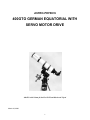
1
ASTRO-PHYSICS 400GTO GERMAN EQUATORIAL WITH SERVO MOTOR DRIVE 400GTO with 130mm f6 StarFire EDFS and Hardwood Tripod March 30, 2000 1 TABLE OF CONTENTS MODEL 400GTO PARTS LIST 3 FEATURES AND SPECIFICATIONS 3 INTRODUCTION 4 Why Polar Alignment is Important Compensation for the Earth’s rotation 4 4 ASSEMBLY INSTRUCTIONS 5 Assemble Pier or Tripod 6 Assemble Mount to Pier or Tripod 6 Altitude and Azimuth Adjustments - Rough Polar Alignment 6 Assemble Cradle Plate (purchased separately) 7 Assemble Counterweight Shaft 7 Attach Mounting Rings (purchased separately) 8 Adjusting the Clutches 8 Balancing Your Telescope 8 SERVO MOTOR DRIVE 9 GTO Control Box - GTOCP2 R.A. and Dec. Cable Connections 12V Connector POWER Indicator Light KEYPAD Connector RS-232 Connectors FOCUS Connector RETICLE Connector AUTOGUIDER Connector +6V Connector N and S Switch 9 9 9 9 9 10 10 10 10 10 10 Prevent the Cables from Tangling Accessory Cables 10 10 GTO Keypad Controller Operation 11 MOUNT MAINTENANCE AND ALIGNMENT: 11 TROUBLESHOOTING – additional tips are in the Keypad instruction 11 INSTALLATION OF ENCODERS AND ENCODER HOUSINGS –400 MOUNT 12 Fitting Declination Encoder Housing 12 Fitting Right Ascension Encoder Housing 12 Periodic Maintenance 13 2 ASTRO-PHYSICS 400GTO GERMAN EQUATORIAL MOUNT WITH SERVO MOTOR DRIVE MODEL 400GTO PARTS LIST 1 1 1 1 1 1 3 1 2 1 400 Equatorial Head with Servo Drive Motors Stainless counterweight shaft with washer stop and black plastic knob (5/16-18 threaded rod) GTO Control Box (Model GTOCP2) and Carrying Bag GTO Keypad Controller with 15’ Coiled Cable D.C. power cord (cigarette lighter adapter) – 8’ long “Y” cable (goes to RA and Dec motors) with extension cable (attaches to the GTO Control Box) Black plastic knobs with 1/4-20 threaded rod 5 and 10mm hex keys Red Caplugs DigitalSky Voice Software (CD-ROM) In order to fully assemble and use your mount, you will need the following items sold separately: mounting plate, pier or tripod, portable rechargeable battery pack and counterweights. Several sizes and types are available for your selection. Many of these items will be discussed throughout these instructions. Several additional options are available: Santa Barbara Instrument Group CCD imaging cameras and ST-4 Autoguider - if you plan to pursue CCD imaging or astrophotography Mounted encoders - you will need these if you plan to use digital setting circles. Keep in mind that these 4000 step encoders which read the position of the shaft are very coarse (324 arc seconds) while the encoders that are built into the servo motor itself is 0.05 arc seconds. JMI Digital setting circles - The go-to keypad will perform most of the functions of the digital setting circles. One advantage of the JMI unit is the ability to move the telescope by hand while the unit displays your position. FEATURES AND SPECIFICATIONS RA/Dec Worm wheel 3” (7.6 cm), 192 teeth, fine-pitched bronze wheel RA/Dec Worm gear Stainless steel RA/Dec shafts 2.5” hollow shafts Counterweight shaft 1.125” diameter stainless steel, removable Latitude range 10 to 64 degrees Azimuth adjustment Approximately 25 degrees Setting circles Porter Slip Ring design Right ascension 10 minute increments, pointer engraved both Northern/Southern Declination 1 degree increments, pointer Motors Zero-cogging servo motors Power Consumption 0.3 amps at sidereal rate, 1.2 amps with both motors slewing Power requirements 12 VDC Capacity Will accommodate refractors up to 5”, reflectors to 6”, Cassegrains to 8” Weight of equatorial head 21 lbs. (9.5 kg) 3 INTRODUCTION The 400GTO German equatorial mount offers many fine features to provide superb performance in a compact, portable package. The DC servo motor drive with GTO computer system, including the keypad controller with its digital display screen and DigitalSky Voice software offer extraordinary sophistication for today’s observer. Whether you enjoy visual astronomy exclusively or plan an aggressive astrophotography or CCD imaging program, this mount will allow you to maximize your night out under the stars. The advanced keypad features allow you to slew automatically to objects in a wide range of databases as well as to any RA/Dec coordinate. A large selection of common names for stars and other objects makes your selection a snap. The rapid slew rate of 5 degrees per second (1200x) allows you to locate objects very quickly and accurately. You will be very pleased with the intuitive operation of this controller. There are no complicated sequences of keystrokes to remember. It is so easy to use that even if you don’t use it for a few months, you will feel at home with the keypad very quickly. DigitalSky Voice software provides additional capabilities to control the movement of your telescope by using two-way verbal communication with a microphone or by a few clicks of your computer mouse (or touchpad). You can remain at the eyepiece while you direct your telescope with verbal commands. DigitalSky Voice is an observing companion who guides you through the universe offering suggestions of objects that are fun and interesting to observe. In order to maximize your pleasure on your first night out, we recommend that you familiarize yourself with the assembly and basic operation of the mount indoors. The temperature will be comfortable, the mosquitoes at bay, and you'll have enough light to see the illustrations and read the manual. Please take particular note of counterbalancing, use of the clutches and operation of the keypad controller. Why Polar Alignment is Important Compensation for the Earth’s rotation If you were to take a long exposure photograph with Polaris (often called the North Star) in the center of the field, you would discover that all stars seem to revolve around Polaris. This effect is due to the rotation of the earth on its axis. Motor driven equatorial mounts were designed to compensate for the earth's rotation by moving the telescope at the same rate and opposite to the earth's rotation. When the polar axis of the telescope is pointed at the celestial pole (polar aligned) as shown in Diagram 1, the mount will follow (track) the motions of the sun, moon, planets and stars. As a result, the object that you are observing will appear motionless as you observe through the eyepiece or take astrophotos. Diagram 1 4 ASSEMBLY INSTRUCTIONS Please read all instructions before attempting to set up your 400 mount. The Model 400 is very rugged, however like any precision instrument, it can be damaged by improper use and handling. Please refer to the following illustrations. The parts are labeled so that we can establish common terminology. The following terms and abbreviations are used interchangeably in these instructions: Polar axis=right ascension axis = R.A. axis = R.A. housing Declination axis = dec. axis = dec. housing 5 Assemble Pier or Tripod Begin by assembling the pier or tripod at the desired observing location. ADJUSTABLE ALUMINUM TRIPOD: Extend the legs to the desired height; secure with the locking levers. Adjust the distance between the legs. Place the legs far enough apart to provide a solid base of support. ADJUSTABLE HARDWOOD TRIPOD: Remove the tripod from its carrying case and attach the shelf to each of the three legs with the knobs provided. Adjust legs to the desired height and spread. Lock in position with the hand knobs. PORTABLE PIER: Slide the three legs onto the nubs of the base. Place the pedestal tube on the base and attach the tension rods. The turnbuckles should be drawn tight until the whole assembly is stiff enough to support your weight without movement. Assemble Mount to Pier or Tripod In order to track the motion of astronomical objects, the polar axis must be positioned so that an imaginary line drawn through the hollow shaft points toward the celestial pole. At this stage of the assembly process, you want to position the mount so that it points roughly north. Place the mount into the top of the pier or tripod so that the threaded R.A. axis opening is on the south side of the pier/tripod. Screw in the three hand knobs to hold the mount in place. Altitude and Azimuth Adjustments - Rough Polar Alignment For rough polar alignment, your goal is to sight the celestial pole when looking through the polar alignment sight hole in the center of the polar axis. You will need to make altitude (up/down) and azimuth (side to side) adjustments to the position of the mount. We recommend that you do your rough polar alignment without the telescope since you may be making major adjustments to the position of the mount at this time. The remainder of the mount, telescope and counterweights would add considerable 6 weight and require more hand effort. Later, you will do your final polar alignment with the telescope and counterweights attached, but the adjustments will be small. 1. If the R.A. encoder housing and encoder adapter are installed (part # ENC400 - Mounted Encoders to use with Digital Setting Circles - are available as an optional purchase), you may remove them to complete these steps. Please refer to the section pertaining to encoders later in the manual. Alternatively, you can simply sight up the side of the polar axis to see Polaris. 2. If you examine the polar axis assembly, you will see that the center of the polar shaft is hollow. You may need to rotate the internal declination shaft by moving the top of the declination axis (or the cradle plate if it is attached) to align the sighthole that has been drilled into it. Now, you can look through the shaft to the other side. 3. Loosen the two black plastic clamp knobs on each side of the mount. Use the 5/16” hex key to loosen the 3/8-16 socket head cap screw on the side of the mount base. If your scope is mounted, support its weight with your other hand since you are loosening a critical bolt. 4. Your goal is to sight Polaris when looking through the polar alignment sight hole in the center of the polar axis. You will need to make altitude and azimuth adjustments to the position of the mount. Azimuth adjustments: Move the entire pier or tripod east or west until the mount is oriented approximately towards the pole (an imaginary line drawn through the hollow shaft). Use the two fine azimuth adjustment knobs, one on each side of the mount, to make adjustments. You must back off the opposing azimuth knob in order to move the other knob in that direction. Altitude (latitude) adjustments: Move the polar axis up or down with the large altitude adjustment knob located at the rear of the mount assembly. We have found that using the turnbuckle on the north leg of our pier also can make fine altitude adjustments, if used. 5. Continue your azimuth and altitude adjustments until you can sight Polaris in the polar alignment sight hole. At this point, you have achieved rough polar alignment, which may be sufficient for casual visual observations, if you are not planning to slew to target objects with the keypad. When the R.A. motor is engaged (the power cord is plugged in), it will compensate for the rotation of the earth and keep the target object within the eyepiece field of view. Your target object will slowly drift since polar alignment at this stage is only approximate. However, you can make corrections with the N-S-E-W buttons of your keypad controller. 6. Snug the two black plastic clamp knobs and one 3/8-16 screw to lock the mount into position. You will complete your polar alignment and calibrate on a star with your keypad controller when your telescope is completely setup and you are ready to observe. Assemble Cradle Plate (purchased separately) Several mounting plates are available for the 400 mount. If you own more than one instrument, you may need more than one plate. Attach your mounting plate with the screws provided. It is important to use the proper screws, please refer to the “Mounting Plate Fastener Chart” included with this manual. Assemble Counterweight Shaft IMPORTANT: Always attach the counterweights before mounting the telescope to the cradle plate to prevent sudden movement of an unbalanced tube assembly which may cause damage or injury. Remember counterweights are heavy and will hurt if they fall on your foot. 1. Thread counterweight shaft onto the Dec. axis. 2. Remove the hand knob and washer from the base of the counterweight shaft. Add sufficient counterweights (6 or 9 lb. counterweights are available) to the counterweight shaft to balance the telescope you intend to use. Always use two hands to attach or move them on the shaft. Reattach the hand knob and washer to the end of the counterweight shaft. This will help to prevent injury if someone accidentally loosens the counterweight hand knob. 7 A firm tightening of the counterweight knob will not damage the surface of the counterweight shaft. The pin that tightens against the stainless counterweight shaft is constructed of brass. Likewise, the bronze sleeve that has been press fit into the center of the counterweight will prevent marring of the shaft as you move the counterweights. Attach Mounting Rings (purchased separately) Our flat plates are constructed with keyhole slots at the location where your mounting rings attach. This feature enables you to partially loosen the screws on your rings just enough to insert them into the larger part of the keyhole, then slide the rings to the narrow part and tighten them with a hex key. You can even accomplish this with the rings on the scope, although this maneuver may be difficult to accomplish with a large, heavy instrument. We prefer this keyhole method to the standard way of completely removing the screws and possibly dropping them in the grass. If you are using a dovetail plate (DOVE08, DOVE15, and DOVELM) on your mount, you will attach your mounting rings to the corresponding sliding bar. Adjusting the Clutches There are two clutch knobs on either side of the right ascension and declination axes. The R.A. and declination motors will not drive the axes until these clutch knobs are engaged. We recommend that you turn the knobs enough to engage the motors while still allowing you to move the scope by hand. It is not necessary to tighten the knobs with force. Balancing Your Telescope For proper operation, the telescope must be adequately counterbalanced. Start by balancing the tube assembly. 1. Tighten the R.A. axis clutch knobs and loosen the Dec. axis clutch knobs so that the telescope tube rotates on the declination axis. Be careful because if your telescope is significantly out of balance, it may swing rapidly in the out of balance direction. 2. If you are using a dovetail plate, loosen the two side knobs and move the sliding bar, with scope attached, forwards and backward. If you are not using the dovetail plate, loosen the hand knob on the mounting rings and slide the tube up or down. The scope is balanced when it stays level with no clutch drag. 3. Now, tighten the declination axis with the dec. clutch knobs and loosen the R.A. clutch knobs. 4. Move the counterweights up or down to achieve balance in R.A. 5. Remember to allow for the extra weight of diagonals, eyepieces, and finderscopes. If the scope moves by itself, even when the clutches are loose, the scope is not fully counterbalanced. A small amount of imbalance is permissible. 8 SERVO MOTOR DRIVE GTO Control Box - GTOCP2 The GTO control box contains all of the circuitry to drive the two servo motors and the logic required to circumnavigate the sky. It will be operational and track at the sidereal rate when connected to both motors of the mount and a power source. In order to control the movement of the mount, you will need to connect at least one of these: • GTO Keypad controller • Computer with astronomical software such as DigitalSky Voice (included) or Software Bisque’sTheSky™ (purchased separately). The GTO Servo Control Box is mounted directly onto the polar axes of the 1200 and 900 mounts and is a stand-alone unit for the 400 and 600E mount. Please remember that this box contains advanced electronics and must be treated with the same care given to other fine equipment. Support the stand-alone unit in a secure manner so that it does not fall and do not place it in the wet grass or dust. We have provided a pouch with a handle that can be hung from a convenient knob on your mount, tripod or pier. You can see that the unit is built to be rugged, however it is not indestructible. R.A. and Dec. Cable Connections Attach one end of the Extension Cable to the 10-pin receptacle labeled “Motors” on the GTO Control Panel and the other end to the “Y” cable, which is attached to the RA and Dec motors. Lock all connectors. The Extension and “Y” cables are included with this mount. 12V Connector Place the DC power cord (included with your mount) into the phono plug outlet marked 12V on the GTO Control Panel and lock in place. Plug the cigarette lighter plug end of the cord into your power source. The acceptable voltage range is 11.5 to 15. Suggested power sources include: portable rechargeable battery pack, auto or marine battery, or power supply (filtered and regulated) for 110 volts with a minimum output of 3 amps at 12V DC. There is no on-off switch. We recommend that you plug the power cable into the servo box after the keypad controller. To turn the unit off, simply disconnect the power cable. Considerations for observatory installations: We suggest that you disconnect your GTO Control Box from 110V when you are not using your mount so that if your observatory experiences a power surge or lightening strike, your mount electronics will not be damaged. If you operate your mount remotely, you will have to leave your power cable connected just as you do for the rest of your electronic equipment. You may want to consider surge protectors or other protective measures to protect from voltage spikes. POWER Indicator Light This LED will remain illuminated when your power source has sufficient output to drive the motors. If the voltage falls below 10 volts, the power light will go out and the motors will stop. The keypad controller will not function properly. If the LED turns yellow, your motors are probably overloaded due to an unbalanced load on your mount. Refer to the troubleshooting section of the manual for the solution. KEYPAD Connector Attach the 5 pin male connector of the keypad controller and lock in place (push in the knurled ring then turn). 9 RS-232 Connectors These serial port connections are used to connect your mount to your PC computer. You must provide your own cables with a 9 pin (DB9) male connector to interface with the GTO panel. We have provided the locking posts to secure the cable firmly. If your serial cable does not have a 9-pin connector, you can use a gender changer or adapter to convert it. When you are controlling the position of the mount with a computer program such as DigitalSky Voice™ or TheSky™, the microprocessor chip located in the servo drive box will send continual RA and Dec coordinate data via the cable connections to your computer. When you use the software to give instruction to slew to a new object, the commands (RA and Dec coordinates) are sent to the mount. We provide two serial port connections on the mount so that you can use two software programs simultaneously. For instance, you can give verbal commands in DigitalSky Voice while using TheSky as a planetarium program. Since the mount will update the RA and Dec coordinates simultaneously, both programs are continually updated with the data from the mount. You can watch the screen display of TheSky to see where your telescope is pointing as it slews. This is most effective if you have a reasonably fast computer with plenty of RAM. If you try this with a 100MHz processor and only 32 MB of RAM, the response time will be slow since both programs must be continuously updated with position data. You must have two serial ports available on your computer to use take advantage of this feature. If you use a laptop, you may need to purchase a PCMCIA adapter to gain an additional serial port. Socket Communications offers adapters for many computers. Check out their web site at www.socketcom.com. FOCUS Connector Attach the 2.5mm phono plug connector of your JMI Motofocus or Meade electric focuser (optional accessories) here. Refer to the section regarding focus adjustment in the GTO Keypad Manual for instructions on using the keypad controller to adjust focus. Alternatively, you can verbally control the focus using the Focus Mode of DigitalSky Voice software. RETICLE Connector If you wish to use a plug-in type guiding eyepiece with an illuminated reticle (available from several manufacturers), insert the 2.5mm phono plug into this connector for power. Reticle brightness can be adjusted with the hand control. Refer to the section pertaining to reticle illuminator adjustment in the GTO Keypad Manual for further information. AUTOGUIDER Connector This connector interfaces with the RJ-11-4 modular jack of an autoguider cable, purchased separately or as part of a CCD Imaging Camera or Autoguider. The autoguider will be functional and ready to go as soon as you plug it in. Please refer to the appropriate manual from the manufacturer for operation of the autoguider. We offer CABTIC (Tracking Interface Cable for SBIG ST-4 and ST-6 camera) and CAB7/8RC (Relay cable for SBIG ST-7 and ST-8 cameras). Please refer to our price list or call for further information. +6V Connector This 6 volt output accepts 2.5mm phono plugs. It is used primarily to power the Pentax 6x7 camera directly from the mount with a cord sold for that purpose (our part # CORD01). N and S Switch Select northern (N) or southern (S) hemisphere as needed. When you slide the switch to the opposite position, the tracking direction of the drive will reverse. The power cord must be removed and re-attached to make this work. Prevent the Cables from Tangling The movement of the mount across the meridian during slewing functions is calculated so that the cables will not tangle if they are set up properly. In addition to the motor and power cables that are provided with the mount, you may have additional cables for other accessories. These may be powered from the GTO Control Panel or from another power source. We suggest that you position your cabling carefully to avoid a tangled mess. When your cables are set up, move the telescope manually throughout the normal range of movement to be sure that the cables do not catch on anything and that you have enough length. Here are a few pointers: Accessory Cables Accessories may include Kendrick Dew Removers, CCD cameras and autoguiders, focus motors, illuminated guiding eyepiece reticles, power cords for the Pentax 6x7 camera, etc. As you attach each accessory, carefully assess the best position to assure complete movement as your telescope slews from one side of the mount to the other. If an external power source is used, determine the optimum location for the battery. We prefer to use tie wraps (not glamorous, but effective) or cable ties (from electronic supply store or catalog) to secure our cables to the mount, telescope, rings or bind 10 them together. Plastic adhesive cable mounts, available from electronic supply stores, are an alternative choice. We prefer to use ties since we cannot bear to attach adhesive cable mounts to our telescopes or mounts. If we use tie wraps to secure several cables together and plan to use that same setup in our next observing session, we keep the ties in place when we disassemble our equipment. The setup for the next session is much quicker. GTO Keypad Controller Operation Please refer to the manual for the GTO Keypad Controller for complete instructions. MOUNT MAINTENANCE AND ALIGNMENT: Under normal operating conditions, no maintenance is required. Your 400GTO is a precision instrument with very accurate worm and wheel adjustments. Please be careful if you place the mount on a flat surface, i.e. the ground or trunk of your car. This is true of any fine instrument. We suggest that you transport and store the mount in a case or in a well padded box. TROUBLESHOOTING – additional tips are in the Keypad instruction The LED on the GTO Control Box changes from red to yellow and the motors stop. The motors are overloaded, probably due to an unbalanced load on your mount. Rebalance your telescope, then press one of the N-S-E-W buttons to reset the keypad. Re-enter the last object on your keypad and the scope will slew to the correct position. Even though your motors had stopped, the logic in the control box retained the scope position in memory. As long as you didn’t change the pointing position of the scope, you are still calibrated. If the scope was moved during re-balancing, simply enter a nearby bright star on the hand controller, press GOTO and allow the mount to finish slewing. You can then move the scope manually or with the N-S-E-W buttons to center the star in the eyepiece, and press the #9 RECAL button. This will recalibrate the mount. Additional explanation: The GTO drive circuit includes logic for overload protection to prevent burning out the expensive servo motors in case of severe overload on the two axes. The primary cause is an unbalanced load in R.A. If the extra load opposes the motor rotation, the motor must work harder to track at the sidereal rate and the current will rise to high levels. If the current exceeds the trip point for more than a minute, the logic will shut the motor off and tracking stops. It typically takes about 4 lb. of unbalance to trip the overload, but a very heavy load of scopes, accessories and counterweights on the mount can decrease this unbalance threshold. The power light goes out and the motors stop. The voltage of your battery has probably gone below 10 volts. If any problems occur, please don't hesitate to contact Astro-Physics for assistance. ASTRO-PHYSICS INC 11250 Forest Hills Road Rockford, IL 61115 Telephone: (815)-282-1513 Fax: (815)-282-9847 [email protected] Recommended reading from our staff: The Backyard Astronomer's Guide, Terence Dickinson and Alan Dyer, Camden House Publishing, 1991The authors, both former editors of Astronomy magazine, offer practical insight into astronomical equipment, finding your way around the sky, polar alignment, using setting circles, and astrophotography. This book provides excellent explanations and is well organized and illustrated. All About Telescopes, Sam Brown, Edmund Scientific Company, 1975. Excellent information regarding the principles of mount construction and operation, using setting circles, eyepiece projection, etc., Illustrations and formulas galore. Many of the instruments pictured are dated, however the underlying principles are timeless. Norton’s 2000.0 Star Atlas and Reference Handbook, edited by Ian Ridpath, J. Wiley Publisher, 1989. Star maps, information regarding polar alignment of German Equatorials and observing techniques. 11 INSTALLATION OF ENCODERS AND ENCODER HOUSINGS –400 MOUNT 400NC (purchased separately) Parts List: 1 Right Ascension (R.A.) Encoder housing (black anodized) 1 Declination (Dec.) Encoder housing (black anodized) 1 R.A. Axis Adapter (clear anodized - silver colored), labeled R.A. 1 Dec. Axis Adapter (clear anodized - silver colored), labeled Dec. To install your encoders, first remove the telescope from your mount. Remove your declination counter weight(s) and declination counterweight shaft. Fitting Declination Encoder Housing 1. If the encoders were purchased with the 400 mount, it is likely that the declination axis adapter and encoder housing have already been installed. No further action will be required, as this encoder will remain in place. 2. If the encoders were purchased separately, the silver-colored Dec. axis adapter may be inside the black Dec. axis encoder housing. If it is, remove it now. 3. Thread the dec. axis adapter into the end of your dec. axis (from where you earlier removed the dec. counterweight shaft). Final tightening should be done with firm hand pressure. Normally the Dec. axis adapter will not be removed. 4. If you look into the black encoder housing, you will see the encoder itself mounted at the rear of the housing. When this installation procedure is complete, the encoder shaft will insert into the center hole of the Dec. axis adapter. This allows the encoder to read the motion of the declination shaft as the declination axis moves. 5. Thread the Dec. encoder housing onto the Dec. axis housing. You may need to wiggle the encoder housing gently to engage the shaft of the encoder with the hole in the center of the Dec. axis adapter. When the threading is complete, tighten up with firm hand pressure since normally this encoder housing will not be removed. 6. Thread the counterweight shaft into the rear of the Dec. encoder housing. Fitting Right Ascension Encoder Housing 1. If the encoders were purchased with the 400 mount, it is likely that the right ascension axis adapter and encoder housing have already been installed. Please continue to read these directions since you may need to remove and reinstall the encoders if you use a polar alignment scope. Since the polar axis telescope and R.A. axis adapter thread into the same location, you will need to switch back and forth between them as needed. If you use the JMI NGC MAX or Mini MAX Digital Setting Circles, you can use the "polar align" mode in these units instead of a polar alignment scope. 2. If the encoders were purchased separately, the silvercolored R.A. axis adapter may be inside the R.A. axis encoder housing. If it is, remove it now. 3. Thread the R.A. axis adapter into the end of your R.A. axis (if your polar alignment scope is fitted you must remove this first along with the polar alignment scope adapter). Use moderate hand pressure to tighten the R.A. adapter since you may need to remove it to install the polar axis telescope at a later time. 12 4. If you look into the black encoder housing, you will see the encoder itself mounted at the rear of the housing. When the installation procedure is complete, the encoder shaft will insert into the center hole of the R.A. axis adapter. This allows the encoder to read the motion of the R.A. shaft as the right ascension axis moves. 5. Now thread the R.A. encoder housing onto the R.A. axis housing. You may need to wiggle the encoder housing gently to engage the shaft of the encoder (located within the R.A. axis housing) with the hole in the center of the R.A. axis adapter. Tighten the 3 thumbscrews evenly to secure in place. 6. The hardware for your encoders is now installed. For actual set-up procedures for Micro MAX, Mini MAX or NGC MAX, digital readouts refer to the relevant operating manual. Periodic Maintenance If you remove the R.A. encoder frequently, you may wish to use a very tiny amount of auto grease on the mating threads. 13