1
CONTENTS
1. Introduction
2. General safety
3. Charge controller installation
4. Mounting systems
5. MC4 connectors
6. 12V Wiring
7. 24V Wiring basics
8. Multiple panels/strings in parallel
9. Battery configurations
10. Inverter wiring
11. Warranty
Copyright © 2014 Renogy. All Rights Reserved.
pg. 2
pg. 2
pg. 3
pg. 5
pg. 10
pg. 12
pg. 15
pg. 16
pg. 19
pg. 22
pg. 24
1
1|
INTRODUCTION
A new RENOGY Off-Grid Solar Kit will provide you with a clean, silent, and sustainable way of ensuring that
batteries are fully charged and capable of providing a continuous supply of electricity. Each kit comes equipped with a high
quality solar panel that features highly efficient silicon solar cells. If you have purchased a RENOGY Off-Grid Solar Kit, a
PWM Solar Charge Controller is also included in the package. This controller will serve as a connector between the solar
panel and the batteries. The solar charge controller will ensure that the battery is charged with the appropriate amount of
solar power as per the battery manufacturer’s recommendations. The solar charge controller ‘charging states’ are optimized
to meet the requirements of most standard lead acid batteries as well as flooded batteries. The RENOGY Off-Grid Solar Kit
also includes a mounting system comprised of sturdy aluminum Z-Brackets as well as the nuts and bolts required to flat
mount a solar panel onto a roof or any other flat surface. If you wish to optimize your panel’s collection of sunlight by tilting
the panel to a different inclination, an adjustable tilt-mount may be purchased separately.
This manual will provide you with instructions on how to assemble the various components of a RENOGY Off-Grid
Solar Kit. Please refer to the separate Renogy Solar Charge Controller Manual for detailed information about the installation,
operation, and programming of the solar charge controller.
Please read the manual carefully before installing or operating the solar kit to prevent personal injury or damage
to the components. If you have any concerns about the suitability of the kit for your application, or doubts about any of the
instructions in this manual, please contact RENOGY Support at 1-800-330-8678.
2|
GENERAL SAFETY
Please read the instruction manual carefully before attempting to carry out any installation
or wiring. Contact Technical support for any questions concerning the installation.
Warning!
2.1 Installation and wiring compliance
Installation and wiring must comply with the local and National Electrical Codes and must be done by a certified electrician.
Please follow these four steps:
1.
2.
3.
4.
Disconnect all power sources before carrying out the installation.
Make sure the correct polarity is observed when making connections between the solar panel, charge controller,
and battery. Damage due to reverse polarity connection is not covered by warranty.
Make sure all wire connections are secured; loose connections may cause sparks.
Wear appropriate clothing and safety gear including protective eyewear when performing any electrical installation.
2.2 Preventing fire and explosion hazards
Working with electronic/electrical equipment may produce arcs or sparks. Thus, such equipment should not be used in
areas where there are flammable materials or gases requiring ignition protected equipment. These areas may include
spaces containing gasoline-powered machinery, fuel tanks, and battery compartments.
2.3 Precautions when working with batteries
Batteries contain very corrosive diluted sulfuric acid as electrolyte. Precautions should be taken to prevent contact
with skin, eyes, or clothing.
Batteries generate hydrogen and oxygen during charging, resulting in the evolution of an explosive gas mixture.
Care should be taken to ventilate the battery area and follow the battery manufacturer’s recommendations. Never
smoke or allow a spark or flame near the batteries.
Use caution to reduce the risk of dropping a metal tool on the battery. It could spark or short circuit the battery or
other electrical parts and could cause an explosion.
Remove metal items such as rings, bracelets, and watches when working with batteries. The batteries can
produce a short circuit current high enough to weld a ring or similar object to the metal, causing a severe burn.
If you need to remove a battery, always remove the ground terminal from the battery first. Make sure that all the
accessories are off so that you do not cause a spark.
Only use properly insulated tools when making battery connections.
Copyright © 2014 Renogy. All Rights Reserved.
2
2.4 Precautions when working with solar panels
With the incidence of sunlight or other light sources on all solar panels, a voltage appears at the output terminals of the
solar panel turning it into a source of electricity. To avoid a shock hazard, make sure the solar panel is covered with an
opaque (dark) material such as paper or cloth during the installation. Do not make contact with the terminals when the panel
is exposed to sunlight or any other light source.
2.5 Precautions when working with charge controllers
If two or more solar panels are connected in a series/parallel make sure that the sum of the short circuit current ratings of all
panel strings does not exceed 80% of the charge controller’s current rating (i.e. 24A for the 30A charge controller). The
open circuit voltage of the solar array (i.e. the maximum voltage across the array) should not exceed 26V when the 12V
setting on the charge controller is used, and may not exceed 52V when the 24V setting on the charge controller is used.
2.6 Routine maintenance
3|
Inspect the solar panels and make sure the surfaces are free from dust, dirt, and other debris; clean with a wet
cloth or glass cleaner if necessary.
Check to make sure all structural components, mechanical fasteners, and electrical connections are secure, clean,
and corrosion-free.
Check and maintain the battery electrolyte levels at regular intervals as per the battery manufacturer’s
recommendations if flooded wet cell lead acid batteries are used.
Check and replace damaged components if necessary
CHARGE CONTROLLER INSTALLATION
The RENOGY Starter and RV Kits come with a PWM- type charge controller to optimally charge your batteries from solar
power. Each charge controller comes with a separate detailed manual. It is recommended that you read the solar charge
controller manual in detail. The instructions in this section are only a brief summary of the information contained in the
manual. Make sure the solar panels and batteries are disconnected from the charge controller before mounting the charge
controller.
3.1 Mounting location
The charge controller should ideally be located in an area relatively close to the battery and should be mounted indoors in a
dry location.
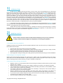
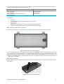
When mounting the charge controller, ensure free airflow through the controller heat sink. There should be at least 4 inches
of clearance above and below the controller to allow cooling. If mounted in an enclosure, ventilation is highly recommended.
Copyright © 2014 Renogy. All Rights Reserved.
3
4”
4
Figure 3.1 Charge controller clearance
Ensure that the mounting location is protected from direct sunlight, high temperature, and water; make sure that the location
has sufficient room to run wires.
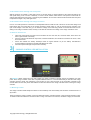
3.2 Marking and drilling the holes
Use a pencil or pen to mark the four holes on the mounting surface. Remove the controller, and drill the holes in the marked
location. Make sure that the holes are sized appropriately to avoid loose screws. If you are mounting the controller on
drywall, it is recommended that you use expansion anchors.
Figure 3.2 Hand drill, pencil and charge controller
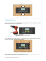
3.3 Securing the controller
Once you have drilled the holes, place the controller on the surface and align the mounting holes with the drilled holes.
Secure the controller in place using mounting screws (not included).
Figure 3.3 Securing the controller with mounting screws
Once the charge controller is mounted, we can show the multiple types of solar panel mounting systems. Please read the
following section to learn more about the mounting system that RENOGY offers.
Copyright © 2014 Renogy. All Rights Reserved.
4
4|
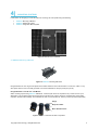
MOUNTING SYSTEMS
In this section we are going to cover the basics for mounting 12V solar panels using the following:
RENOGY Mounting Z-Bracket
RENOGY Rail Mount System
RENOGY Single Pole Mount System
Figure 4.1 Rail Mount vs. Z-Bracket
4.1 RENOGY Mounting Z-Bracket
Figure 4.2 RENOGY Mounting Z-Bracket
Using Z-Brackets for 12V off-grid solar panels is the easiest method to mount the modules on roofs, RVs, cabins, or any
other place where a screw can easily penetrate. One set of Z-Brackets is used per panel (four per set).
Using Z-Brackets on an RV roof: “Flat Mount”
When mounting a panel using RENOGY Z-Brackets, a well-nut (also known as “expansion nut”) is often used on a predrilled hole. This procedure safely secures the panel on thin RV roofs. Using a well-nut is recommended, as the rubber
expansion prevents water leakage. The Z-Bracket set does not include well nuts, and they must be purchased separately.
Flange
Neoprene rubber
Brass threaded insert
Figure 4.3 Types of well-nuts and their composition
Copyright © 2014 Renogy. All Rights Reserved.
5
It is recommended that the roof is at least 3/8" thick to achieve a strong hold of the solar module. The following example
involves mounting an RNG-100D module on a 3/8” RV roof.
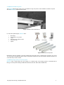
Parts needed
4x #10-32x3/4” machine screws with round head
4x #10 lock washer
4x #10 flat washer
4x #10-32x5/8” Well nut (aka Expansion nuts)
anti-seize lubricant
Parts included with Z-brackets
4x M6x1.0 bracket bolts
4x M6 flat washer
4x Lock washer
4x M6x1.0 nuts
Tools required:
Hand drill
3/8” Drill bit (size depends on the body diameter of the well nut)
Socket wrench
10mm socket
Phillips screw driver (flat head if using combination drive machine screws)
Caulking gun with waterproof caulk (or sealant approved by your RV dealer).
Step 1: Attaching the Z-Bracket to a solar panel
Locate the mounting holes on the solar panel. RENOGY Solar Panels have four mounting holes on each side.
Figure 4.4 RNG-100D with Z-Brackets attached
It is recommended that the outer mounting holes be used as shown in Figure 4.4. Please refer to Figure 4.6 for instructions
on the proper order to mount the hardware. First, insert the M6x1.0 bracket bolt included in the kit, with the head on the
inside of the frame. Place the Z-Bracket over the bracket bolt, followed by the M6 flat washer and the lock washer. Insert
the M6x1.0 nut and fasten it with your fingers to hold it place. Use a socket wrench with a 10mm socket to torque the nut at
___ lbs/ft. (do not over-tighten).
Step 2: Mark and drill holes
With the Z-Brackets attached to the frame, the panel can be laid on a mounting surface, making it easier to mark the holes
for the well-nut.
Figure 4.5 Marking the holes to be drilled
Copyright © 2014 Renogy. All Rights Reserved.
6
Once the holes are properly marked, use the appropriate size bit to drill the holes. The well-nuts used in this example had a
body diameter of 3/8”, therefore, we used a 3/8” drill bit. Carefully drill the holes, and make sure the well-nut fits properly.
Step 3: Attaching the panel to the roof
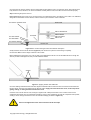
Figure 4.6 illustrates the correct way to use the well-nut. The rubber flange has to be flushed on the roofline. The Z-Bracket,
along with the flat washer and lock washer, hold the well-nut in place when the screw is fastened.
Solar Panel
#10-32x3/4” machine screw
M6x1.0 bracket bolt
#10 lock washer
#10 flat washer
M6 flat washer
M6 lock washer
M6x1.0 nut
Z-bracket
#10-32x5/8” Well nut
3/8” RV roof
Figure 4.6 RV overall mounting structure with hardware description
Gently insert the well nut into the drill hole (Figure 4.6). Be careful not to push the well nut flange completely
into the holes. Make sure the flange is flushed on the roofline.
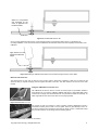
Before attaching the panel to the roof, a film of caulk can be laid between the RV roof and the Z-Bracket. Even though the
well-nut provides a watertight bond, this provides additional sealant.
Sealant
Figure 4.7 Applying sealant under Z-Bracket
Once the caulking sealant bead has been laid, align the Z-Brackets with the well nut holes. Insert the #10 lock washer into
the #10-32x3/4” machine screw followed by the #10 flat washer. Apply anti-seize fluid to the screw, as this will prevent
galling, locking, or seizing with the well-nut brass insert.
Insert the screw into the well-nut hole, and begin to tighten it with a Philips screwdriver. If the machine screw is has a
combination drive head, then use a flat head screwdriver. As the screw is tightened, the well-nut compresses and expands,
creating a secure strong hold that is free from air and water leakage (as shown in Figure 4.8).
Do not over-tighten the screw. Do not exceed 5 in-lbs of torque.
Warning!
Copyright © 2014 Renogy. All Rights Reserved.
7
Well-nut is compressed
and expanded as the
screw is tightened into
the brass thread
3/8” RV roof
Figure 4.8 Finalized Z-Bracket on RV
Once you have tightened all the screws, ensure that the panel is secured before driving the RV. To finalize the RV
mounting installation, cover the head screws and Z-Brackets with sufficient sealant; this will completely seal the base of the
Z-Bracket.
Apply sealant on screw
heads and Z-Bracket
edges
Figure 4.9 Sealing the Z-Bracket with sealant recommended and approved by an RV dealer.
Well-nuts and blind holes
The well-nut does not only work for thin RV roofs, but also works in blind holes. Tightening a well-nut in a blind hole will
cause the body to expand and apply pressure against the walls of the hole. This also creates a secure hold of the solar
module.
Using the Z-Brackets on a house roof
The Z-Brackets can also be used on a house roof if the proper roof penetration sealant is
used between the roof and the Z-Bracket. Figure 4.10 shows a 60W (RNG-60D) panel
mounted into a shingle roof with Z-Brackets. A roof penetration sealant is necessary, as
water might leak into the house if the holes are not properly sealed.
Figure 4.10 RNG-60D on a roof
The panels can also be mounted in custom mounting systems. Figure 4.11 shows a
homemade mounting frame made of a wood pallet. This is a great example of DIY offgrid work. Customers are not limited to mounting the panel on a RV or residential rooftop;
they can also freelance on the design of their mounting system.
Figure 4.11 RNG-100D mounted on wood stand
Copyright © 2014 Renogy. All Rights Reserved.
8
4.2 RENOGY Rail Mount System
The RENOGY Rail Mounting System is not only available for large 24V panels, but also available for smaller 12V panels
such as the RENOGY 70W and 100W modules.
Figure 4.12 RNG-100D with Rail Mount
For roofs with asphalt shingles, RENOGY offers:
Mid-clamps
End-clamps for 12V panels
L-feet
Quick Mount PV ® Flush mounts
5 and 10 ft. rails
Splices
Mid-clamp
End-clamp
L-feet
Rails
Figure 4.13 Rail Mount components
Rail Mounting offers the capability of mounting multiple solar panels side by side. If greater length is necessary, the 5 ft. and
10 ft. rails can be extended with splices. Keep in mind that the thickness of each solar module is different; therefore, the
correct End-clamp must be ordered.
4.3 RENOGY Single panel pole mount system
RENOGY offers a single panel pole mount system for 4” diameter poles. This mounting system is compatible with all
Renogy 12V solar panels including the RNG-50D, RNG-50P, RNG-70P, RNG-100D and RNG-100P.
Copyright © 2014 Renogy. All Rights Reserved.
9
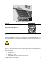
Figure 4.14 Pole mount system with RNG-100D
To find out more about RENOGY Mounting Systems
please visit
http://goo.gl/9C21Ke
Or scan the following QR code with your
smartphone:
5|
MC4 CONNECTORS
The Positive (+) and Negative (-) outputs of a solar panel are fed through a watertight junction box. The
appropriate wire length is wired to the junction box for further connections. The solar panels supplied in each kit are
provided with approximately 3 ft. each of both Positive and Negative wires that are pre-connected to the junction box. The
free ends of the wires are terminated with a special type of mating connector also known as an MC4 Connector. These
connectors allow for ease in extending the wires for further connections.
Please do not cut off the solar panel connectors; the warranty will be voided.
Caution!
5.1 General information about MC4 connectors
Each RENOGY Solar Panel will have an MC4 Connector System that consists of male and female connectors. This type of
connector system is easy to install and uses a “snap-in” type of safety locking clips to lock the two mating connectors. The
“snap-in” feature avoids unintentional disconnection. The mating contacts are sealed against the ingress of dust and water.
Specifications are as follows:
Contact diameter: 4 mm
Maximum rated current: 30A
Maximum system voltage: 1000V
Gauge size: 14, 12, 10 AWG
Degree of ingress protection when connected and properly locked: IP67
Copyright © 2014 Renogy. All Rights Reserved.
10
Temperature range: −40°C to +90°C
TÜV Rheinland approved
5.2 General information about MC4 Connectors
The MC4 Connectors mentioned in this manual have been designated “Male” and “Female” ends based upon the
characteristics of the mating contact inserts within the terminals. However, in the solar industry, the “Female” MC4
Connector is used for the positive (+) lead of a panel, and the “Male” MC4 Connector its used for the negative (−) lead of a
panel as shown in Figure 5.2.
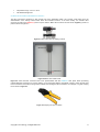
Figure 5.1 MC4 Connectors and mating contacts
Junction box
Male MC4
−
Female MC4
+
Figure 5.2 Back view of RNG-100D
Figure 5.2 shows the MC4 Connectors that come preassembled with each RENOGY solar panel. When purchasing
unassembled MC4 Connectors for custom cabling, it is recommended that the appropriate crimper is used; this will avoid
loose connections and create a strong internal contact when mating the MC4 Connectors. An example of a great crimping
tool is shown in Figure 5.3.
Figure 5.3 Crimping tool (#14-10 AWG)
Copyright © 2014 Renogy. All Rights Reserved.
11
6|
12V WIRING
In this section, we will show the basic 12V and 24V connections for off-grid systems that use a PWM- type controller.
Please follow them thoroughly.
The battery must first be wired to the charge controller before the solar panel is connected
to the charge controller.
Caution!
6.1 Battery to charge controller
The battery(s) must first be connected to the charge controller before proceeding to any other connections. Most PWM
Controllers have automatic battery voltage detection, and the controller must detect what voltage level it will be charging at.
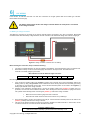
Figure 6.1 Charge controller connected to a 12V battery
Before starting the connection, keep in mind the following:
The charge controller should be as close as possible to the batteries. This helps keep line loss to a minimum level.
Remember to always use the recommended gauge size based on the input current. The PWM 30A LCD
Controller can handle gauges up to 8 AWG.
NEC maximum current for different copper wire sizes
AWG
16
Max. Current
10A
Refer to Figure 6.1 for connections.
1.
2.
4.
12
20A
10
30A
8
55A
6
75A
4
95A
2
130A
0
170A
First, connect the negative cable to the negative (−) battery post. The best way to secure the battery cable to the
battery post is by using a ring terminal. A bolt is sufficient to secure the ring terminal onto the battery post; doing
so will allow for great electrical contact. Next, connect the bare stranded portion of the cable to the negative (−)
battery input terminal on the charge controller.
Similarly to the instructions described above, connect the positive cable to the positive (+) battery post. For
protection, an in-line fuse can be added to this cable. This is usually done with a fuse holder. If opting for an in-line
fuse, please do the following before connecting the positive (+) cable to the charge controller:
3.
14
15A
Make sure the fuse holder’s gauge wire size is matched.
Attach the fuse holder to the line with a butt connector or by soldering it.
Once the fuse holder is in place, don’t attach a fuse just yet. Connect the bare stranded portion of the cable to the
positive (+) battery terminal on the charge controller.
The fuse can be sized according to the amount of panels in parallel for a PWM Controller. In other words, current
in would be current out. Here is a formula to calculate the fuse size:
Controller to Battery Fuse =
(Number of Panels in Parallel) × (Short Circuit Current of Panel) × 1.25
Copyright © 2014 Renogy. All Rights Reserved.
12
Example: 200W Kit (2 Panels)
RNG-100D has a short circuit current of 5.75 amps, hence:
Controller to Battery Fuse = (2) × (5.75A) × 1.25 = 14.38A ≈ 15A
5.
6.
Once the fuse is properly sized, ensure that all connections were made properly, and that there are no loose
connections present. Finally, insert the fuse into the fuse holder. The controller should power on.
If opting for no in-line fuse, connect the bare stranded portion of the cable to the positive (+) battery input
terminal on the charge controller directly from the positive (+) battery post, bypassing the fuse holder. The
controller should power on.
Be careful not to short the battery. Reverse polarity connection will damage the charge
controller and the resulting damage will not be covered by warranty.
Warning!
6.2 Information about solar panels and PWM Controllers
When connecting a solar panel to the charge controller, please ensure that the correct type of panel or panel array is used.
Please note the following about PWM Controllers:
12V panels should be used with 12V battery systems only
24V panels or 12V panels configured in series to make 24V should be used with 24V battery systems only
The solar array should not max out the rated power of the controller. Failure to obey this rule may result in the
controller overheating or catching fire.
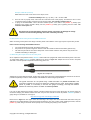
6.3 Extending the output wires of the solar panel
As we explained in the previous section, RENOGY Solar Panels are equipped with cables terminated by MC4 Connectors.
To extend these cables, RENOGY provides adapter kits as shown in Figure 6.2. Adapter kits can be found in Complete
Solar Kits or sold as separate components at www.renogy-store.com.
Fig. 6.2. MC4 Adapter Kit
Adapter kits are sold in different lengths, and the basic gauge size is #12 AWG. Unassembled MC4 Connectors can also be
purchased separately to make a custom adapter cable suitable for different length specifications.
Caution!
The typical connection for 12V panels using a PWM Controller is a parallel connection. This
connection increases the current, but keeps the voltage level the same. When placing multiple
panels in parallel, it is necessary to size the wire gauge accordingly, and keep the distance
between the solar array and the controller as close as possible.
Long runs of cable between the panel(s) and the controller increase the line loss if the gauges are not properly sized. We
recommend keeping the distance between the solar array and the controller as close as possible. RENOGY provides a
gauge-sizing tool, available for no charge at:
http://www.renogy-store.com/category-s/1864.htm
Please refer to Figure 6.3. This figure shows the extending of the output wires of the RNG-100D Solar Panel using the
adapter kit. The polarity labeled on the panel’s leads should be the only ones to follow. When adapting the leads, mark the
positive (+) cable; doing so will avoid reverse polarity when connecting the panel(s) to the controller.
Copyright © 2014 Renogy. All Rights Reserved.
13
Figure 6.3 Solar panel and adapter kit
6.4 Solar Panel to charge controller
Once the battery is connected to the charge controller and the panel(s) are positioned and mounted in the desired location,
we are ready to connect the panel(s) to the charge controller. Panels should be mounted in a place that is free from shading
by neighboring obstacles such as vents, air-conditioners, TV antennas, etc.
The panel MUST be covered with a dark cloth to prevent the solar cells from producing
energy; this will prevent and reduce shock hazard, which can be life threatening.
Hazard!
Please refer to Figure 6.4 when completing the following connections:
1.
2.
3.
4.
5.
First, mate the “Male” MC4 Connector from the solar panel that has the negative (−) label with the “Female” MC4
Connector of your adapter kit as shown in Figure 6.4. Then connect the bare stranded portion of the cable to the
negative (−) solar input terminal on the charge controller.
Next, mate the “Female” MC4 connector from the panel that has the positive (+) label with the “Male” MC4
connector of your adapter kit as show in Figure 6.4.
The positive (+) solar cable can be fused for protection; an in-line fuse can be added to this cable in the same
way as described in the instructions for battery to controller connection. Please refer to section 6.1 and follow the
same procedure to find the proper size of this fuse.
Once the fuse holder is in place, don’t attach a fuse just yet. Connect the bare stranded portion of the cable to the
positive (+) solar terminal on the charge controller. Ensure that all connections are made properly, and that there
are not any loose connections present. Finally, insert the fuse into the fuse holder and remove the protective cloth.
If there is enough sunlight present, the controller’s solar LED indicator/icon on the LCD display should show that it
is now charging your battery(s).
If opting for no in-line fuse, connect the bare stranded portion of the adapter cable to the positive (+) solar input
terminal on the charge controller. Remove the protective cloth. If there is enough sunlight present, the controller’s
solar LED indicator/icon on the LCD display should show that it is now charging your battery(s).
Copyright © 2014 Renogy. All Rights Reserved.
14
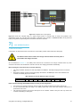
Figure 6.4 Completed 12V off-grid system
Figure 6.4 shows the complete wiring of a typical off-grid system. It includes fuses for safety and protection. This
configuration shows only one panel and one battery connected to the controller. In Sections 8 and 9, more panel and
battery configurations (respectively) will be described. Instructions will follow.
7|
24V WIRING BASICS
7.1 General information
In this section we will show the basic connections for a 24V battery system. Please follow them thoroughly.
The batteries must first be wired to the charge controller before the solar panel is
connected to the charge controller.
Caution!
As we mentioned in Section 6.1, the battery bank must first be connected to the charge controller before any other
connections are made. This will allow the controller to set the 24V charging parameters automatically.
Before starting the connections keep in mind the following:
The charge controller should be as close as possible to the batteries. This helps keeping line loss to a minimum
level.
Remember to always use the recommended gauge size based on the total input current. The PWM 30A LCD
controller can handle gauges up to 8 AWG.
NEC maximum current for different copper wire sizes
AWG
Max. Current
16
10A
14
15A
12
20A
10
30A
8
55A
6
75A
4
95A
2
130A
0
170A
Please note the following about PWM controllers running in 24V configuration:
24V panels or 12V panels configured in series to make 24V should be used with 24V battery system only
It is not recommended that you charge a 12V battery system with a 24V solar array. Doing so will result in a
performance loss of 50%.
The solar array should not max out the rated power of the controller. Failure to obey this rule may result in the
controller overheating or catching fire.
Copyright © 2014 Renogy. All Rights Reserved.
15
7.2 Overall system connections
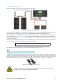
Please refer to Figure 7.1 for the overall wiring diagram for a 24V system.
Figure 7.1 Completed 24V off-grid system
As you can see from Figure 7.1, the batteries are configured in 24V by placing two identical 12V batteries in series.
Likewise, the solar array is configured in 24V by placing two identical 12V panels (e.g. RNG-100D) in series.
The connections for a 24V off-grid system are very similar to the 12V connections. The process should be followed in the
same way as outlined in Sections 6.1 to 6.4. The only difference in instruction is that the fuses are now calculated by the
number of parallel strings. A string is a set of panels configured in series. Figure 7.1 shows a single string that consists of
two 12V panels in series.
Remember, when configuring the panels in series, the voltages will add and the amperage in the current loop will remain
the same. For this reason, we can see a slight change in the fuse equation:
Controller to Battery Fuse =
(Number of strings in Parallel) × (Short Circuit Current of Panel) × 1.25
With this being said, the same steps for a 12V system should be followed. Please read Sections 6.1 to 6.4.
8|
MULTIPLE PANELS/STRINGS IN PARALLEL
A parallel connection is achieved by joining all of the positive (+) and negative (-) nodes together. When placing panels in
parallel, it is recommended that the voltage levels are within specification. In other words, the Vmp (maximum power voltage)
of the panels must all be within 10% of each other. Typically, connecting panels in parallel is achieved through using
identical panels. A simple way to place panels/strings in parallel is by using a branch connector, shown in Figure 8.1.
Figure 8.1 Pair of MC4 Branch Connectors
Remember to always use the recommended gauge size based on the total array current. Sizing
the cable incorrectly may result in melting wires and/or fire.
Caution!
Copyright © 2014 Renogy. All Rights Reserved.
16
8.1 Two adjacent panels in parallel (12V systems)
Figure 8.2 Two RNG-100D Panels in parallel
One of the most basic solar configurations involves wiring two solar panels in parallel. This parallel configuration will
increase the current output while the output voltage remains the same. Fig. 8.2 above shows the arrangement for
connecting two solar panels in parallel with one pair of MC4 Branch Connectors. This arrangement is applicable if two solar
panels will be mounted adjacent to one another. This connection requires one (1) pair of MC4 Branch Connectors. When
the panels are mounted at different locations- that is, separated by a distance, the panels must be extended with MC4
Extension Cables (sold separately).
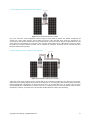
8.2 Three adjacent panels in parallel (12V systems)
Figure 8.3 Three RNG-100D Panels in parallel
Three solar panels is the maximum amount of panels that can be connected in parallel if they are adjacent to one another,
without using extra cabling. Fig. 8.3 above shows the arrangement for connecting three solar panels in parallel. Remember
that this arrangement is applicable if the three solar panels are to be mounted adjacent to one another. This connection
requires two (2) pairs of MC4 Branch Connectors. When one or multiple panels are mounted at different locations- that is,
separated by a distance, the panels need to be extended with MC4 Extension Cables (sold separately).
Copyright © 2014 Renogy. All Rights Reserved.
17
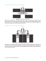
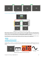
8.3 Four panels in parallel (12V systems, 2x2 configuration)
Figure 8.4 Four RNG-100D Panels in parallel
Fig. 8.4 shows the arrangement for connecting four solar panels in parallel. This arrangement is applicable if the solar
panels are to be mounted in a 2x2 configuration as shown above. Please note that the positioning of the junction boxes
must be followed for the cables to reach the MC4 Branch Connectors. This connection requires three (3) pairs of MC4
Branch Connectors. When one or multiple panels are mounted at different locations- that is, separated by a distance, the
panels must be extended with MC4 Extension Cables (sold separately).
8.3 Four panels in parallel (12V systems, 1x4 configuration)
Figure 8.5 Four RNG-100D Panels in parallel
Fig. 8.5 above shows the arrangement for connecting four solar panels in parallel. This arrangement is applicable if the
solar panels are to be mounted in a 1x4 configuration as shown above. For this configuration you will need to purchase
4x1.5’ MC4 Solar Extension Cables. This connection requires a three (3) pairs of MC4 Branch Connectors. When one or
multiple panels are mounted at different locations- that is, separated by a distance, the panels must be extended with MC4
Extension Cables (sold separately).
Copyright © 2014 Renogy. All Rights Reserved.
18
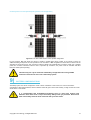
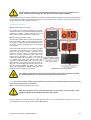
8.4 Four panels in series-parallel (24V systems, 2x2 configuration)
Figure 8.6 Four RNG-100D Panels in series-parallel configuration
For 24V systems, Fig. 8.6. Shows two strings of panels in parallel. Each string consists of two panels in series. No
additional cabling is required if the solar panels are to be mounted in a 2x2 configuration as shown above. Please note the
orientation of the junction boxes. This connection requires a one (1) pair of MC4 Branch Connectors. When one or multiple
panels are mounted at different locations- that is, separated by a distance, the panels must be extended with MC4
Extension Cables (sold separately).
This 24V array can only be used with a 24V battery configuration when using a PWM
Controller. Please do not use it with a 12V battery system.
Note
9|
BATTERY CONFIGURATIONS
The battery system can also be configured to create a “bank” of batteries. In this section, we cover the most basic
configurations. When wiring batteries, extreme attention should be given. Never short a battery, as high currents can cause
severe burns or even death.
It is recommended that insulated/non-conducting tools be used when working with
batteries. Never leave tools on top of the battery. Always wear eye protection. Never touch
both of the battery terminals at the same time with your bare hands.
Hazards!
Copyright © 2014 Renogy. All Rights Reserved.
19
9.1 Series connection of batteries (12V)
Figure 9.1 Two 6V batteries connected in series
When two or more batteries are connected in a series, their voltages add up, but the Amp-Hour (AH) capacity remains the
same. Fig. 9.1 shows two 6V batteries in parallel. For example, say each battery has 225 Ah. This wiring will form a 12V
battery bank with a capacity of 225 Ah. Notice that the cables connecting the batteries in series are of heavier gauge than
the ones coming from the controller. These cables have to be of heavier gauge because when power is drawn from an
inverter, it involves large amounts of current. This interconnection cable is often sized according to the power of the inverter.
9.2 Parallel connection of batteries (12V)
Figure 9.2 Two 12V batteries connected in parallel
When two or more batteries are connected in parallel, their voltage remains the same but the Amp-hour ratings add up. Fig.
9.2 shows two 12V batteries in parallel forming a “bank”. For example, say each battery has 100 Ah. When connected in
parallel they will form a battery bank of 12V with a capacity of 200 Ah. Notice that the cables connecting the batteries in
parallel are of heavier gauge than the ones coming from the controller. These cables have to be of heavier gauge because
when power is drawn from an inverter, it involves large amounts of current. This interconnection cable is often sized
according to the power of the inverter.
The negative cable from the controller to the battery should be placed at the opposite end of the battery bank. Figure 9.2
shows this connection.
Copyright © 2014 Renogy. All Rights Reserved.
20
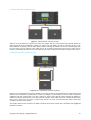
9.3 Series – Parallel connection of batteries (12V)
Figure 9.3 Four 6V batteries connected in series – parallel
Fig. 9.3 shows two strings in parallel; each string consists of two 6V batteries in series. For example, say each battery has
225 Ah. Each string would have a voltage of 12V with a capacity of 225 Ah. When these strings are paralleled, the total
capacity of the battery bank will be 12V at 450Ah. Notice that the cables connecting the batteries in series and parallel are
of heavier gauge than the ones coming from the controller. These cables have to be of heavier gauge because when power
is drawn from an inverter, it involves large amounts of current. This interconnection cable is often sized according to the
power of the inverter. Also, the negative cable from the controller to the battery should be placed at the opposite end of the
battery bank. Figure 9.3 shows this connection.
9.4 Series connection of batteries (24V)
Figure 9.4 Two 12V batteries connected in series
Wiring two 12V batteries in series as shown in Fig 9.4 will result in a 24V system. The same idea applies if you place four
6V batteries in series (Fig 9.5). Remember that when batteries are in series, the voltages add, but the total capacity of a
string of batteries stays the same. For example, if two 12V batteries with 150Ah rating are wired in series, the resulting
system would be 24V at 150Ah. Because of this, it is mandatory that the batteries are identical when they are wired
in series.
Copyright © 2014 Renogy. All Rights Reserved.
21
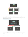
Figure 9.5 Four 6V batteries connected in series
9.5 Series-Parallel connection of batteries (24V)
Figure 9.6 Four 12V batteries connected in series – parallel
Multiple strings of batteries can be wired in parallel to increase the capacity. Figure 9.6 shows a battery bank with two
strings of batteries. Each string consists of two 12V batteries in series. For example, if wiring four 12V/150Ah batteries like
as shown in Figure 9.6, then each string will have a total capacity of 24V/150Ah. By paralleling these strings, the total
capacity would be 24V/300Ah. Because of this, it is mandatory that the batteries are identical.
Each parallel string can also consist of 4x6V batteries to make 24V per string as shown in Figure 9.5. Remember that the
negative cable from the controller to the battery should be placed at the opposite end of the battery bank.
10|
INVERTER WIRING
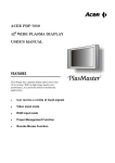
10.1 General information about power inverters
A power inverter, or inverter, is an electrical device that changes direct current (DC) to alternating current (AC); the
converted AC can be at any required voltage and frequency with the use of appropriate transformers, switching, and control
circuits.
DC In
AC Out
Figure 10.1 Simple diagram on how the inverter works
Copyright © 2014 Renogy. All Rights Reserved.
22
Please read these instructions carefully before attempting to carry out any installation and
wiring. Contact Technical support for any questions concerning the installation.
Warning!
This equipment should be installed, adjusted, and serviced by qualified electrical maintenance personnel familiar with the
construction and operation of solar/electrical equipment and the hazards involved. Failure to observe this precaution may
result in bodily injury and/or damage to property.
10.2 Wiring instructions
Step 1: Select the right input voltage
Input voltage can be 12V/24V/48V depending on which
products are used. It is recommended that the inverter be
powered by a battery or battery bank, as the current
drawn from the inverter can become extremely high.
Step 2: Connecting inverter to battery
Set the switch to OFF position (inverter and appliances).
Connect the battery cables to their respective colors on
the inverter i.e. black cable goes to the black terminal on
the inverter, and the red cable goes to the red terminal
on the inverter.
Please refer to Fig. 3. Each end of the battery tray cables
should have a “ring terminal” type of connector. These
connectors make it easy to achieve a secure and strong
connection. Once the cables are connected and bolted
down to the inverter, connect the black cable to the
negative post of the battery (-). Then, connect the red
cable to the positive post of the battery (+). If connecting
to a battery bank, make sure that the black cable
connects to the negative battery post (-) at the end of the
bank (opposite to the positive battery post as shown on
Fig. 3). It is recommended that a fuse be placed on the
hot line (positive) between the battery and inverter.
Please refer to the owner’s manual for the proper wire
gauge size and fuse ratings for each inverter.
Figure 10.2 Inverter wiring diagram
The negative battery terminal and the chassis ground of the inverter should be connected
to a system ground. This is a safety measure to prevent electrical shock!
Ground!
NOTE: The charge controller and the inverter should be connected to the same battery terminals (same connecting
points shown in Figure 10.2), no exceptions.
Step 3: Connecting electrical appliances to inverter
Make sure the power load is within the rated power of the inverter. The start power of the
appliances should not exceed the peak power of the inverter.
Caution!
Once the devices are connected to the AC outlet, they are ready to be powered. When the inverter is not in use, it is
recommended that you turn off the inverter (switch in OFF position).
Copyright © 2014 Renogy. All Rights Reserved.
23
11|
WARRANTY
By acquiring the products of RNG Group Inc. ("Renogy"), you have purchased quality. As a sign of confidence in this quality,
we are pleased to grant you the following warranties and guarantees for our photovoltaic products:
LIMITED WARRATNY: Renogy warrants these products will be free from defects in material and manufacture for the
following periods from the date of purchase:
One (1) year RENOGY PWM Charge Controllers
One (1) year on the rest of accessories
Five (5) years on RENOGY Solar Panels (material and workmanship)
25 years power output warranty on RENOGY Solar Panels
This warranty extends only to the original purchaser. The Customer’s sole and exclusive remedy and the entire liability of
Renogy, its suppliers and affiliates for breach of the warranty is, either to replace the Product or component parts or to
refund the purchase price of the Product. This warranty does not cover labor. Repaired or replaced products are warranted
for the remainder of the original warranty period only. No employee, agent, dealer or other person is authorized to give any
warranties on behalf of Renogy not expressly set forth in this limited warranty.
The warranty does not cover failures result from incorrect handling, product modifications, installation, conversion or
additions, supplements, operation, natural elements, excessive or deficient energy supply, chemicals, the effect of solid
bodies or deliberate damage. If Renogy determines that the problem with the Product is not due to a manufacturing defect
in Renogy’s workmanship or materials, or otherwise does not qualify for warranty repair, then the Customer will be
responsible for the costs of all necessary repairs and expenses incurred by Renogy.
The warranty shall be asserted with Renogy in writing enclosing a copy of the invoice and a description of the defect/loss of
performance within the warranty period. Renogy shall accept no returns of modules without the previous written request for
this. Within five (5) business days of the date of notification, Renogy will provide the Customer with an RMA number and the
location to which the Customer must return the defective Product. Any Product returned for warranty service shall be
shipped at the expense and risk of the Customer. The Customer must return the entire Product (or, if authorized by Renogy,
the defective component parts), within fifteen (15) days after issuance of the RMA number. Renogy will be under no
obligation to accept any returned Product that does not have a valid RMA number. All parts that Renogy replaces shall
become Renogy’s property on the date Renogy ships the repaired Product or part back to the Customer. Renogy will use all
reasonable efforts within thirty (30) days of receipt of the defective Product to repair or replace such Product. If a warranty
claim is invalid for any reason, the Customer will be charged at Renogy’s then-current rates for services performed and will
be charged for all necessary repairs and expense incurred by Renogy. If Renogy determines that a warranty claim is valid,
it will ship the repaired or replaced Product to Customer at Renogy’s cost.
RENOGY MAKES NO OTHER WARRANTIES OR CONDITIONS, EXPRESS OR IMPLIED, INCLUDING, BUT NOT
LIMITED TO, ANY IMPLIED WARRANTY OR CONDITION OF MERCHANTABILITY OR FITNESS FOR A PARTICULAR
PURPOSE OR ANY IMPLIED WARRANTY OR CONDITION ARISING OUT OF A COURSE OF DEALING, CUSTOMER
OR USAGE OF TRADE.
LIMITATION OF LIABILITY
UNDER NO CIRCUMSTANCES WILL RENOGY OR ITS AFFILIATES OR SUPPLIERS BE LIABLE OR RESPONSIBLE
FOR ANY LOSS OF USE, INTERRUPTION OF BUSINESS, LOST PROFITS, LOST DATA, OR INDIRECT, SPECIAL,
INCIDENTAL, OR CONSEQUENTIAL DAMAGES OF ANY KIND REGARDLESS OF THE FORM OF ACTION,
WHETHER IN CONTRACT, TORT (INCLUDING NEGLIGENCE), STRICT LIABILITY OR OTHERWISE, EVEN IF
RENOGY OR ITS AFFILIATE OR SUPPLIER HAS BEEN ADVISED OF THE POSSIBILITY OF SUCH DAMAGE.
Some states do not allow the exclusion or limitation of incidental or consequential damages, so these limitations may not
apply to you. Neither Renogy nor its affiliates or suppliers will be held liable or responsible for any damage or loss to any
items or products connected to, powered by or otherwise attached to the Product. The total cumulative liability to Customer,
from all causes of action and all theories of liability, will be limited to and will not exceed the purchase price of the Product
paid by Customer. This warranty gives you specific legal rights and you may also have other legal rights that vary from state
to state.
Copyright © 2014 Renogy. All Rights Reserved.
24