1
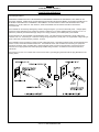
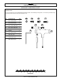
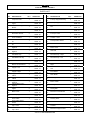
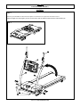
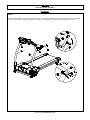
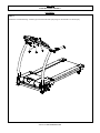
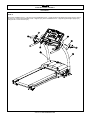
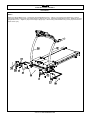
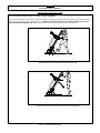
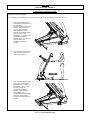
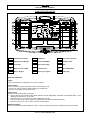
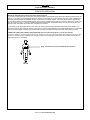
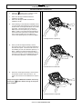
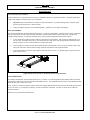
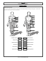
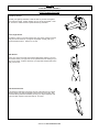
USER’S MANUAL
FX20HR MOTORIZED TREADMILL
MODEL NUMBER: FX20HR
USER WEIGHT LIMITATION: 265lbs.
TOLL FREE CUSTOMER SERVICE NUMBER: 1.888.800.1167
SERIAL NUMBER (found on frame):
2
FX20HR MOTORIZED TREADMILL
PRECAUTIONS
Precautions:
WARNING: To reduce the risk of burns, fire, electric shock, or injury to persons, read the following important precautions
and information before operating the treadmill. It is the responsibility of the owner to ensure that all users of this treadmill
are adequately informed of all warnings and precautions.
•
Use the treadmill only as described in this manual.
•
Place on a level surface, with 2 meters (6 feet) of clearance behind it. Do not place the treadmill on any surface
that blocks air openings. To protect the floor or carpet from damage, place a mat under the treadmill.
•
When choosing a location for the treadmill make sure that the location and position permit access to a plug.
•
Keep the treadmill indoors, away from moisture and dust. Do not put the treadmill in a garage or covered patio, or
near water.
•
Do not operate the treadmill where aerosol products are used or where oxygen is being administered.
•
Keep children under the age of 12 and pets away from the treadmill at all times.
•
The treadmill should not be used by persons weighing more than 120kgs. (265lbs.)
•
Never allow more than one person on the treadmill at a time. Wear appropriate exercise clothing when using the
treadmill. Do not wear loose clothing that could become caught in the treadmill. Athletic support clothes are
recommended for both men and women. Always wear athletic shoes. Never use the treadmill with bare feet,
wearing only stockings, or in sandals.
•
When connecting the power cord, plug the power cord into a grounded circuit. No other appliance should be on
the same circuit.
•
Always straddle the belt and allow it to start moving before stepping onto the belt.
•
Always examine your treadmill before using to ensure all parts are in working order.
•
Allow the belt to fully stop before dismounting.
•
Never insert any object or body parts into any opening.
•
Follow the safety information in regards to plugging in your treadmill.
•
Keep the power cord away from the incline wheels and do not run the power cord underneath your treadmill. Do
not operate the treadmill with a damaged or frayed power cord.
•
Always unplug the treadmill before cleaning and/or servicing. Service to your treadmill should only be performed
by an authorized service representative, unless authorized and/or instructed by the manufacturer. Failure to
follow these instructions will void the treadmill warranty.
•
Never leave the treadmill unattended while it is running.
Visit us at: www.evofitness.com
3
FX20HR MOTORIZED TREADMILL
POWER REQUIREMENTS
Power Requirements:
IMPROPER CONNECTION OF THE EQUIPMENT GROUNDING CONNECTOR CAN RESULT IN A RISK OF AN
ELECTRIC SHOCK. CHECK WITH A QUALIFIED ELECTRICIAN OR SERVICE MAN IF YOU ARE IN DOUBT AS TO
WHETHER THE PRODUCT IS PROPERLY GROUNDED. DO NOT MODIFY THE PLUG PROVIDED WITH THE
PRODUCT, IF IT WILL NOT FIT THE OUTLET; HAVE A PROPER OUTLET INSTALLED BY A QUALIFIED
ELECTRICIAN.
This treadmill can be seriously damaged by sudden voltage changes in your home’s electrical power. Voltage spikes,
surges and noise interference can result from weather conditions or from other appliances being turned on or off. To
reduce the possibility of treadmill damage, always use a surge protector (not included) with your treadmill.
Surge protectors can be purchased at most hardware stores. The manufacturer recommends a single outlet surge
protector with a UL 1449 rating as a Transient Voltage Surge Suppressor (TVSS) with a UL suppressed voltage rating of
400V or less and an electrical rating 120VAC, 15 amps.
This treadmill must be grounded to reduce the risk of electrical shock. Grounding provides a path of least resistance for
electric current, should the treadmill malfunction. This treadmill comes with an electrical cord having an equipmentgrounding conductor and a grounding plug. Always plug the power cord into a surge protector, and plug the surge
protector into an appropriate outlet that is properly installed and grounded in accordance with all local codes and
ordinances.
This product is for use on a nominal 120-volt circuit, and has a grounding plug that looks like the plug illustrated in the
drawing below.
Visit us at: www.evofitness.com
4
FX20HR MOTORIZED TREADMILL
PREASSEMBLY
Open the boxes:
You are now ready to open the boxes of your new equipment. Make sure to inventory all of the parts that are included in
the boxes. Check the Hardware Comparison Chart for a full count of the number of parts included for this product to be
assembled properly. If you are missing any parts or have any assembly questions call the manufacturer.
Gather your tools:
Before starting the assembly of your unit, make sure that you have gathered all the necessary tools you may require to
assemble the unit properly. Having all of the necessary equipment at hand will save time and make the assembly quick
and hassle-free.
Clear your work area:
Make sure that you have cleared away a large enough space to properly assemble the unit. Make sure the space is free
from anything that may cause injury during assembly. After the unit is fully assembled, make sure there is a comfortable
amount of free area around the unit for unobstructed operation.
Invite a friend:
Some of the assembly steps may require heavy lifting. It is recommended that you obtain the assistance of another
person when assembling this product.
User Weight Limitation:
Please note that there is a weight limitation for this product. If you weigh more than 120kgs. (265lbs.) it is not
recommended that you use this product. Serious injury may occur if the user’s weight exceeds the limit shown
here. This product is not intended to support users whose weight exceeds this limit.
Visit us at: www.evofitness.com
5
FX20HR MOTORIZED TREADMILL
HARDWARE COMPARISON CHART
Hardware chart:
For your convenience, we have identified the hardware used in the assembly of this product. This chart is provided to help
you identify those items that may be unfamiliar to you.
NO.
DESCRIPTION
QTY.
70
M4 x 15mm Screw
19
76
M6 X 15mm Screw
2
77
M8 x 18mm Allen Bolt
2
78
M8 x 50mm Allen Bolt
2
88
Washer
4
100
M8 x 30mm Screw
2
A
Allen Key Tool
1
B
Screw Driver Tool
1
C
Allen Wrench Tool
1
88
76
100
77
78
A
70
C
B
MILIMETERS
Visit us at: www.evofitness.com
6
FX20HR MOTORIZED TREADMILL
PARTS LIST
NO.
DESCRIPTION
QTY.
Computer Insert
1
2
Console Housing Upper
1
3
Console Housing Bottom
1
Safety Key
1
EKG Pulse Sensor
2
1
4
5
Front Handlebar
1
7
Handlebar Cover - Left
#1
1
8
Handlebar Cover - Left
#2
1
9
Handlebar Cover Right #2
1
10
Handlebar Cover Right #1
1
Handlebar Grip
2
Handlebar End Cap
2
EKG Pulse Wire
2
6
11
12
13
14
Motion Control Sensor
2
Upright - Left
1
Upright - Right
1
17
Upright Base Cover Left #1
1
18
Upright Base Cover Left #2
1
19
Upright Base Cover Right #2
1
20
Upright Base Cover Right #1
1
21
Upright Base CoverUpper
2
Base Frame
1
Fold Up Support
1
Power Plate
1
25
Power Plate Plastic
Frame
1
26
Base Frame Tube End
Cap - Front
2
27
Base Frame Tube End
Cap - Rear
2
15
16
22
23
24
ORDER NO.
NO.
DESCRIPTION
QTY.
Fold Up Support Bushing
2
Fold Up Support Insert
1
Nut
1
Spacer
1
Foot Up Locker
1
Base Frame Rubber
Cushion - Rear
2
Transportation Wheel
2
Console Plate
1
Motor Hood
1
Side Rail
2
Deck End Cap - Right
1
Deck End Cap - Left
1
Motor Bottom Cover
1
41
Motor Hood Side Cover Right
1
20HR -15
42
Motor Hood Side Cover Left
1
20HR -16
43
Front Roller
1
20HR -17
44
Rear Roller
1
20HR -18
45
Running Belt
1
20HR -19
46
Motor Holder
1
20HR -20
47
Driving DC Motor
1
20HR -21
48
Driving Belt
1
20HR -22
49
Elevation Control Board
1
20HR -23
50
Motor Control Board
1
20HR -24
51
Running Deck
1
20HR -25
52
Side Rail Guider
6
Running Deck Rubber
Cushion
8
Elevation Support Frame
1
20HR -01
28
20HR -02
29
20HR -03
30
20HR -04
31
20HR -05
32
20HR -06
33
20HR -07
34
20HR -08
35
20HR -09
36
20HR -10
37
20HR -11
38
20HR -12
39
20HR -13
40
20HR -14
20HR -26
53
20HR -27
54
Visit us at: www.evofitness.com
ORDER NO.
20HR -28
20HR -29
20HR -30
20HR -31
20HR -32
20HR -33
20HR -34
20HR -35
20HR -36
20HR -37
20HR -38
20HR -39
20HR -40
20HR -41
20HR -42
20HR -43
20HR -44
20HR -45
20HR -46
20HR -47
20HR -48
20HR -49
20HR -50
20HR -51
20HR -52
20HR -53
20HR -54
7
FX20HR MOTORIZED TREADMILL
PARTS LIST
NO.
55
DESCRIPTION
Elevation Support
Frame End Cap #1
QTY.
2
Plastic Clamp - Upper
2
Plastic Clamp - Bottom
2
Bracket
2
Elevation Support
Frame End Cap #2
2
Deck Frame
1
Elevation Motor
1
Elevation Motor Gear
Sleeve
1
Gas Shock
1
Deck Wheel
2
PU Cushion
1
20 x 40mm Washer
2
Driving Belt Adjustment
bolt
1
M16 Nylon Nut
1
Deck Rubber Cushion
Bolt
8
M4 x 15mm Screw
27
Console Housing
Screw
10
Plastic Fixing Insert
6
Side Rail Guider Screw
12
Rubber Cushion Screw
4
Roller Adjustment Bolt
3
M6 x 15mm Screw
4
M8 x 18 Allen Bolt
6
M10 x 50mm Allen Bolt
4
79
Transportation Wheel
Bolt
2
80
Elevation Motor Fixing
Bolt
1
M10 x 63mm Bolt
1
56
57
58
59
60
61
62
63
64
65
66
67
68
69
70
71
72
73
74
75
76
77
78
81
ORDER NO.
NO.
20HR-55
82
20HR -56
83
20HR -57
84
20HR -58
85
20HR -59
86
20HR -60
87
20HR -61
88
20HR -62
89
20HR -63
90
20HR -64
91
20HR -65
92
20HR -66
93
20HR -67
94
20HR -68
DESCRIPTION
QTY.
ORDER
NO.
M10 x 68mm Allen Bolt
1
20HR 82
Pivot Shaft
1
20HR 83
Deck Wheel Bolt
2
20HR 84
Fold Up Stopper
1
20HR 85
Elevation Support Frame
Fixing Bolt
2
20HR 86
6mm Washer
3
20HR 87
Washer
10
20HR 88
10mm Washer
2
20HR 89
M8 Nylon Nut
7
20HR 90
M10 Nylon Nut
2
20HR 91
M10 Nut
1
20HR 92
20HR 93
N/A
Gas Shock Fixing Spacer
2
20HR 94
95
Base Frame Rubber
Cushion - Front
4
20HR 95
20HR -69
96
Elevation Control Board
Fixing Insert
6
20HR 96
20HR -70
97
Handlebar
1
20HR 97
20HR -71
98
Running Deck Cross Brace
1
20HR 98
20HR -72
99
Running Deck Cross Brace
Foam
1
20HR 99
20HR -73
100
M8 x 30mm Screw
4
20HR 100
20HR -74
101
SPRING
1
20HR 101
20HR -75
102
TRANSPORTATION
WHEEL BRACKET
1
20HR 102
20HR -76
20HR -77
20HR -78
20HR -79
20HR -80
20HR -81
Visit us at: www.evofitness.com
8
FX20HR MOTORIZED TREADMILL
PARTS DIAGRAM
A MAJORITY OF THE PARTS SHOWN HERE HAVE BEEN PREASSEMBLED AT THE FACTORY.
Visit us at: www.evofitness.com
9
FX20HR MOTORIZED TREADMILL
PARTS DIAGRAM
A MAJORITY OF THE PARTS SHOWN HERE HAVE BEEN PREASSEMBLED AT THE FACTORY.
Visit us at: www.evofitness.com
10
FX20HR MOTORIZED TREADMILL
ASSEMBLY
STEP 1:
Remove your treadmill from the carton and place it on the floor in an open area as shown in FIG 1.
Raise the Right and Left Uprights (16 and 15) and secure with two Washers (88) and M10 x 58mm Bolts (78).
FIG. 1
Visit us at: www.evofitness.com
11
FX20HR MOTORIZED TREADMILL
ASSEMBLY
STEP 2:
Rotate up the Handlebar (97) down as shown in FIG 2. Secure the Handlebar (97) in place using two M8 x 18 Allen Bolt
(77) from underneath. Finally, fully tighten the two M8 x 18 Allen Bolt (77) at the pivot points as shown in FIG 3.
Visit us at: www.evofitness.com
12
FX20HR MOTORIZED TREADMILL
ASSEMBLY
STEP 3:
Secure the Console Housing – Bottom (3) to the Console Plate (35) using two Screws M6 x 15 Screw (76).
Visit us at: www.evofitness.com
13
FX20HR MOTORIZED TREADMILL
ASSEMBLY
STEP 4:
Slide the Handlebar Cover – Left #2 (8) and Handlebar Cover – Right #2 (9) onto the Front Handlebar (6). Connect each
of the EKG Pulse Wire (13) to each of the EKG Pulse Sensor (5).
Secure the Front handlebar (6) to the Handlebar (97) using two M8 x 30mm Screw (100).
Visit us at: www.evofitness.com
14
FX20HR MOTORIZED TREADMILL
ASSEMBLY
STEP 5:
Attach the Handlebar Cover – Left #1 (7) to the Handlebar Cover – Left #2 (8) and Left Upright (15) using six M4 x 15mm
Screws (70). Attach the Handlebar Cover – Right #1 (10) to the Handlebar Cover – Right #2 (9) and Right Upright (16)
using six M4 x 15mm Screws (70).
Visit us at: www.evofitness.com
15
FX20HR MOTORIZED TREADMILL
ASSEMBLY
STEP 6:
Attach the Upright Base Cover – Left #2 (18) and Upright Base Cover – Left #1 (17) over the Left Upright (15). Secure
using three Plastic Fixing Insert (72) and three M4 x 15mm Screw (70). Attach the Upright Base Cover – Right #2 (19) and
Upright Base Cover – Right #1 (20) over the Right Upright (16). Secure using three Plastic Fixing Insert (72) and four M4 x
15mm Screw (70).
Visit us at: www.evofitness.com
16
FX20HR MOTORIZED TREADMILL
FOLDING INSTRUCTIONS
FOLLOW THESE INSTRUCTIONS TO FOLD UP YOUR TREADMILL:
Your treadmill can be folded up for space saving storage space. Simply lift the deck up from the rear of the treadmill and
fold up until it locks in place. TO PREVENT INJURY BE SURE YOU HAVE A FIRM HOLD WHEN RAISING THE DECK.
You will hear a “click” sound as the lock engages.
Stand behind the treadmill and lift the deck up.
Raise the deck up until the lock engages.
Visit us at: www.evofitness.com
17
FX20HR MOTORIZED TREADMILL
UNFOLDING INSTRUCTIONS
FOLLOW THESE INSTRUCTIONS TO UNFOLD YOUR TREADMILL:
To unfold the treadmill for use, begin by standing behind and supporting the deck with your hands. Next release the lock
with your foot by stepping on the release lever. TO PREVENT INJURY BE SURE YOU HAVE A FIRM HOLD ON THE
DECK BEFORE RELEASING THE LOCK. Slowly lower the deck until it rests securely on the ground.
Support the deck and release the lock with your foot.
Slowly lower the deck until it rests securely on the ground.
Visit us at: www.evofitness.com
18
FX20HR MOTORIZED TREADMILL
TRANSPORT INSTRUCTIONS
How to fold up the treadmill:
Your treadmill can be folded up for space saving storage. To do this follow the instructions here:
1.
Start by first folding up the
running deck as described on
the FOLDING
INSTRUCTIONS page in this
manual. Remove the lock
pin from Transportation
Wheel bracket as shown.
Then lift the treadmill a little
bit up from the end of
handlebars. You will see the
Transportation Wheel
Bracket spring out. Insert the
lock pin back to the
Transportation Wheel
bracket.
2
1
2.
Lift the deck up from the rear
of the treadmill and fold up
until it locks in place.
3.
Once the treadmill is in place
step on the Transportation
Wheel Bracket to make the
wheel back to place. Insert
the lock pin back to
Transportation Wheel
Bracket. Then follow the
UNFOLDING and
STABILIZER ADJUSTMENT
instruction pages in this
manual to level the frame to
the floor.
1
2
Visit us at: www.evofitness.com
19
FX20HR MOTORIZED TREADMILL
COMPUTER OPERATION
A
Time/Distance/Height
F
Stop/Enter
K
Laps / Running Track
B
Speed/Calories/Weight
G
Incline UP/DOWN
L
Program Guide
C
Scan/Hold
H
Pulse/Incline/Age
M
Start
D
Motion Control On/Off
I
Custom Save
N
Speed UP/DOWN
E
Metric / English
J
Recovery Program
O
Safety Key
BUTTON FUNCTIONS:
START
Press to start exercise at initial speed of 0.5 mph / 0.8 km/h.
STOP / ENTER
a. Press to confirm program and preset function values setting mode.
b. Press to run setting procedure before pressing the START KEY.
c. Press to stop exercise during workout time.
SCAN / HOLD
Switch the LED window display information.
a. Factory setting to auto switch between TIME, SPEED, PULSE / DISTANCE, CALORIES and INCLINE LEVEL. Each
display group will show for 10 seconds.
b. Press the button once to display only TIME, SPEED and PULSE.
c. Press the button the 2nd time to display only DISTANCE, CALORIES and INCLINE LEVEL.
rd
d. Press the button the 3 time to return to the auto switch display.
MOTION CONTROL
Press to activate the MOTION CONTROL function. Follow the MOTION CONTROL operating instructions for details.
Visit us at: www.evofitness.com
20
FX20HR MOTORIZED TREADMILL
COMPUTER OPERATION
CUSTOM SAVE
When selecting the custom program from C1 to C3, follow the instructions to press this button and save the program as
your own custom workout program. Follow the C1-C3 CUSTOM PROGRAM operating instructions for details.
RECOVERY
Press to start the RECOVERY function to test your physical condition after a workout. Follow the RECOVERY operating
instructions for details.
SPEED UP / DOWN
a. Press to increase/decrease exercise speed by 0.1mph / km/h.
b. Hold the button to rapidly increase/decrease speed by 0.5mph / km/h per second. Release the button to stop the
function.
c. Press to select programs and preset related function value.
INCLINE UP / DOWN
a. Press up or down to change incline level.
IMPORTANT INFORMATION:
SAFETY KEY
The safety key must be inserted into the slot on the console in order to operate the treadmill. Always insert the safety key
and attach the clip to your clothing at your waist before beginning your workout. If you should encounter problems and
need to stop the motor quickly, simply pull on the cord to disengage the safety key from the console. To continue
operation first turn the power switch to OFF and set the speed controller to stop. Next turn the power switch to ON and
reinsert the safety key into the console.
ENGLISH / METRIC CONVERSION
The treadmill computer display can show metric and English information. This should be preset for your area by the
factory. However, in case the treadmill needs to be converted between metric and english readout, please follow the
procedure below:
Set the POWER SWITCH to ON. Press the START button on the computer and hold it. Insert the SAFETY KEY then
release the START button. The computer will sound one short beep. Press the START button to switch between
ENGLISH and METRIC and press STOP/ENTER button to confirm the setting. The computer will sound a long beep and
will return to the POWER ON mode with the new setting.
POWER ON
Set the POWER SWITCH, located on the base frame, to ON and insert the SAFETY KEY. All LED windows light up with a
short beep sound. “U1” displays in the LAP window, TIME/DISTANCE displays the user weight factory setting value “150”
lbs or “68” kg, SPEED/CALORIES displays the user height factory setting value “67” inches or “170” cm, and
PULSE/INCLINE displays the user age factory setting value “35”. If there is any user information that has been input and
saved, all LED windows will display the information from the last input user information. If no further button inputs are
made within 3 minutes, the computer will enter the SLEEP MODE. Press any button to return to the POWER ON mode.
SLEEP / DISPLAY MODE
When the power is ON the computer will automatically enter SLEEP MODE if it is left idle for 3 minutes without receiving
any input. Press any button to return to POWER ON status when the computer is in the SLEEP MODE.
To cancel the SLEEP MODE feature using the DISPLAY MODE and always keep the console display on, pull out the
safety key, press and hold the SPEED UP and DOWN buttons, insert the safety key to power on the treadmill. After one
short beep sound the TIME LED window will show “ON” (SLEEP MODE feature on) or “OFF” (SLEEP MODE feature off).
Press the INCLINE UP and DOWN buttons to switch between “ON” and “OFF” then press STOP/ENTER to save the
setting and return to POWER ON mode.
OPERATING INSTRUCTIONS:
QUICK START
When the treadmill is in POWER ON status, press the START button to activate the QUICK START program. The SPEED
LED will count down 3 seconds with 3 short beep sounds then start from 0.5 mph / 0.8 km/h. Press the SPEED UP/DOWN
buttons to change the speed. Press the INCLINE UP/DOWN buttons to elevate the treadmill. The TIME, CALORIES and
DISTANCE will count up from 0.
Visit us at: www.evofitness.com
21
FX20HR MOTORIZED TREADMILL
COMPUTER OPERATION
PAUSE/STOP
During the workout press the STOP/ENTER button once to pause the treadmill. Press the STOP/ENTER button twice to
delete all workout data and return to POWER ON status.
COOL DOWN
After completion of each program the TIME LED window will show “COOL” and blink then start a one-minute cool down
procedure. Time counts down from 01:00 to 00:00 and speed stays at 2 mph / 3.2 km/h and the incline level stays at level
0. After the time counts down to 00:00 the belt stops and returns to PAUSE/STOP status. Press the STOP/ENTER button
to return to POWER ON status. To escape the cool down procedure press the STOP/ENTER button once anytime during
the process to enter the PAUSE/STOP status and press the STOP/ENTER button again to enter the POWER ON status.
RECOVERY
Recovery is the feature to let the user test their physical condition after a workout. The recovery rating is determined by
measuring how quickly the user’s pulse slows down after the workout to justify the user physical condition. The faster the
pulse slows down, the better the user’s physical condition. User’s can record their recovery rating after each workout to use
for reference. To operate the RECOVERY, press the “RECOVERY” button after completing a workout. The treadmill will
enter the PAUSE/STOP status. Put both hands on the hand pulse sensors within 10 seconds (for models equipped with a
chest belt pulse transmitter, keep the chest belt on, no need to hold the hand pulse). The pulse receiver will scan and
detect the user’s pulse in 10 seconds and enter the RECOVERY procedure. TIME counts down from 01:00 to 00:00. The
SPEED LED window will show the RECOVER RATING after the one-minute count down. Record the rating for future
comparison.
During the RECOVERY procedure, if you want to stop the RECOVERY and stop workout, press the STOP/ENTER button
and return to POWER ON status.
During the RECOVERY procedure, if you want to continue the previous program, press the START button to continue the
previous program.
After pressing the RECOVERY button, if the pulse receiver fails to scan and receive the user’s pulse the computer will stay
at PAUSE/STOP status. Press the STOP/ENTER button to return to POWER ON status or press the START button to
continue the previous program.
COMPUTER OPERATION:
Before selecting the program, a user ID needs to be selected. For the first time user, please set up the user information
and assign your USER ID from U 1 to U 9. Press the SPEED UP/DOWN buttons to select the user ID when the computer
is in POWER ON mode.
SET UP USER INFORMATION
After selecting the USER ID the SPEED LED window will show the previous setting for user body weight or the factory
setting value of “150” lbs or “68” kg and be blinking. Press the SPEED UP/DOWN buttons to set the user body weight then
press the STOP/ENTER button to confirm and save.
After setting the user height the TIME LED window will show the previous setting for user height or the factory setting value
of “67” inches or “170” cm and be blinking. Press the SPEED UP/DOWN buttons to set the user height then press the
STOP/ENTER button to confirm and save.
After setting the user weight the PULSE LED window will show the previous setting for user age or the factory setting value
of “35” and be blinking. Press the SPEED UP/DWON buttons to set the user age then press the STOP/ENTER button to
confirm and save.
OPERATING PROGRAM
After completing the user information set up the LAP/USER ID LED window will show “P1”. Press the SPEED UP/DOWN
buttons to select a P1 – P8 program or C1-C3 user program then press the STOP/ENTER button to confirm. Prior to
starting the selected program, follow the procedure to operate the different programs as below:
PROGRAM 1 – TARGET TIME
If P1 is selected, the TIME LED window shows “30:00” as the preset workout time. Press the SPEED UP/DOWN buttons to
set target workout time. Press the STOP/ENTER button to save the target time and press the START button to start the
program. Speed starts from 2.0 mph / 3.2 km/h. Incline starts from level 0. Press the SPEED UP/DOWN buttons to adjust
the speed and press the INCLINE UP/DOWN buttons to adjust the incline level. TIME counts down from the target time to
zero.
Visit us at: www.evofitness.com
22
FX20HR MOTORIZED TREADMILL
COMPUTER OPERATION
PROGRAM 2 – TARGET DISTANCE
If P2 is selected, the DISTANCE LED window shows “0.00”. Press the SPEED UP/DOWN buttons to set the target
distance. Press the STOP/ENTER button to save the target distance and press the START button to start the program.
Speed starts from 2.0 mph / 3.2 km/h. Incline starts from level 0. Press the SPEED UP/DOWN buttons to adjust the speed
and press the INCLINE UP/DOWN buttons to adjust the incline level. DISTANCE counts down from the target distance.
PROGRAM 3 – TARGET CALORIES
If P3 is selected, the CALORIES LED window shows “0”. Press the SPEED UP/DOWN buttons to set the target calories.
Press the STOP/ENTER button to save the target calories and press the START button to start the program. Speed starts
from 2.0 mph / 3.2 km/h. Incline starts from level 0. Press the SPEED UP/DOWN buttons to adjust the speed and press
the INCLINE UP/DOWN buttons to adjust the incline level. CALORIES count down from the target calories.
PROGRAM 4 – INTERVAL INCLINE
If P4 is selected, the TIME LED window shows the factory setting value of “24:00” and is blinking. Press the SPEED
UP/DOWN buttons to adjust the workout time. Every adjustable section equals 4 minutes. Press the STOP/ENTER button
to save the setting and press the START button to start the program. The computer will change the incline level following
the factory setting pattern. Press the SPEED UP/DOWN buttons to adjust the speed.
PROGRAM 5 – INTERVAL SPEED
If P5 is selected, the TIME LED window shows the factory setting value of “24:00” and is blinking. Press the SPEED
UP/DOWN buttons to adjust the workout time. Every adjustable section equals 4 minutes. Press the STOP/ENTER button
to save the setting and press the START button to start the program. The computer will change the speed following the
factory setting pattern. Press the INCLINE UP/DOWN buttons to adjust the incline level.
PROGRAM 6 – WEIGHT LOST
If P6 is selected, the TIME LED window shows the factory setting value of “30:00” and is blinking. Press the SPEED
UP/DOWN buttons to adjust the workout time. Every adjustable section equals 5 minutes. Press the STOP/ENTER button
to save the setting and press the START button to start the program. The computer will change the speed and incline level
following the factory setting pattern.
PROGRAM 7 – 5K SELF LEARING AND COMPETITION
If P7 is selected, the DISTANCE LED window shows “5”(KM) or “3”(MILE). Press the START button to start the program.
Press the SPEED UP/DOWN buttons to adjust the speed and press the INCLINE UP/DOWN buttons to adjust the incline
level.
PROGRAM 8 – HEART RATE CONTROL
If P8 is selected, the TIME LED window shows the factory setting value of “60:00” and is blinking. Press the SPEED
UP/DOWN buttons to adjust the workout time. Every adjustable section equals 3 minutes. Press the STOP/ENTER button
to save the setting then the TARGET HEART RATE displays in the PULSE LED window and is blinking. The factory
TARGET HEART RATE setting is based on 85% of the maximum user heart rate. The maximum user heart rate is
calculated using the formula: 220 minus the user age. As an example, for age 35 the maximum user heart rate should be
185 and 85% of the maximum user heart rate will be 157. Press the SPEED UP/DOWN buttons to adjust the TARGET
HEART RATE according to your own physical condition or your doctor’s instruction then press the STOP/ENTER buttons to
save the setting.
Press the START button to start the three minute WARM UP program. Speed starts from 2.0 mph / 3.2 km/h and the
INCLINE LEVEL starts from level 0. Keep your hand on the hand pulse grips all the time during this workout in order to
monitor your pulse correctly. During the program, if the heart rate monitor fails to sense the user’s pulse you will see “P”
blinking in the PULSE LED window. If the heart rate monitor senses the pulse properly the PULSE DOT LED blinks and
the correct pulse readout shows on the PULSE LED window. The computer will sense the user’s pulse every 30 seconds.
During the warm up program you can press the STOP/ENTER button to pause or stop the program or press the START
button to re-start the program. Other buttons will not react during this warm up process.
During the warm up program, if the heart rate monitor fails to sense the user’s pulse (the PULSE LED will display a blinking
“P”) the computer will not change the speed. If the heart rate monitor senses the user’s pulse properly but the actual user’s
pulse does not reach 65% of the max. heart rate (( 220-age) x 65%) then the speed will increase by 0.5 mph / 0.8 km/h
every 30 seconds. If the actual pulse reaches 65% of the max. heart rate the speed will remain unchanged. If the actual
pulse remains at 65% of the max. heart rate for more than one minute the speed will be maintained until the warm up
program is finished.
Visit us at: www.evofitness.com
23
FX20HR MOTORIZED TREADMILL
COMPUTER OPERATION
If the actual user’s pulse fails to reach 65% of the max. heart rate within the first 3 minutes of the warm up program, the
computer will continue a second 3 minute warm up program. All workout information continues to count up and the timer
counts down from 3:00. During the second 3 minute warm up the computer will change the incline level instead of the
speed. If the heart rate monitor fails to sense the user’s pulse (the PULSE LED will display a blinking “P”) the computer will
not change the incline level. If heart rate monitor senses the user’s pulse properly but the actual user’s pulse does not
reach 65% of the max. heart rate (( 220-age) x 65%) then the incline level will be increased by 1 level every 30 seconds. If
the actual pulse reaches 65% of the max. heart rate the incline level will remain unchanged. If the actual pulse remains at
65% of the max. heart rate for more than one minute the speed will be maintained until the warm up program is finished.
If the actual user’s pulse fails to reach 65% of the max. heart rate within the second 3 minute warm up, the computer will
continue a third 3 minute warm up program. All workout information continues to count up and the timer counts down from
3:00. During the third 3 minute warm up both speed and incline remain unchanged regardless the actual pulse. If the time
counts down to 0 and 65% of the max. heart rate still cannot be achieved then the TIME LED will show “FAIL” and the
program will stop and return to POWER ON status.
After the warm up program is completed, if the actual pulse reaches 65% of the max. heart rate, the computer will enter the
HEART RATE CONTROL program. TIME counts down from the previous setting. Distance and Calories continue to count
up from the warm up program. During the HEART RATE CONTROL program the heart rate monitor will sense the actual
user’s pulse every 30 seconds. If the actual user’s pulse does not reach 85% of the max. heart rate then the incline level
will be increased by 1 level every 30 seconds. If the actual user’s pulse reaches 85% of the max. heart rate then the
treadmill performance will be remain unchanged. If the actual user’s pulse is greater than 85% of the max. heart rate, the
incline level will be reduced by 1 level. Speed will remain unchanged until the incline level increases up to 15% or down to
0%. If the incline level is up to 15% and 85% of the max. heart rate still cannot be reached then the speed will be
increased by 0.5 mph / 0.8 km/h every 30 seconds. If the incline level decreases down to 0% and the actual user’s pulse is
still greater than 85% of the max. heart rate then the speed will be decreased by 0.5 mph / 0.8 km/h every 30 seconds.
If the actual user’s pulse remains above 85% of the max. heart rate for more than 3 minutes the HEART RATE CONTROL
program will shut down and enter a one minute COOL DOWN program.
When the TIME counts down to 0, the HEART RATE CONTROL program is completed and the computer enters a oneminute COOL DOWN program.
After the COOL DOWN program the computer will return to POWER ON status.
The purpose of HEART RATE CONTROL program is to keep the user’s pulse between 65% of the max. heart rate and
85% of the max. heart rate to achieve the most efficient workout result.
C1 – C3 CUS