1
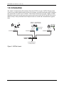
500 A Huntmar Park Drive
ASTi
ACENet User Guide
Document: DOC-02-ACENet-UG-1
Advanced Simulation Technology inc.500A Huntmar Park Drive, Herndon, Virginia, 20170 USA
Revision G (May, 2012)
Product Name: ACENet
Document Updates:
• Updated to version 2 revision F for inclusion of the Voisus Server product line (11/11/11).
• Added supported switches and updated VLAN FAQ (05/15/12).
ASTi Telestra 4 ACENet User Guide
© Copyright ASTi 2010-12.
Restricted Rights: Use, duplication, or disclosure by the Government is subject to restrictions as set forth in subparagraph (c)(1)(ii) of the Rights in Technical Data and Computer Software clause at DFARS 252.227-7013.
This material may be reproduced by or for the U.S. Government pursuant to the copyright license under the
clause at DFARS 252.227-7013 (1994).
ASTi
500-A Huntmar Park Drive
Herndon, VA 20170
Table of Contents
1.0. Introduction. . . . . . . . . . . . . . . . . . . . . . . . . . . . . . . . . . . . . . . . . . . . . . . . . 1
Figure 1: ACENet Layout .................................................................................................1
2.0. ACENet Requirements . . . . . . . . . . . . . . . . . . . . . . . . . . . . . . . . . . . . . . . . 3
2.1. ACENet Switch Requirements ....................................................................................3
2.2. ACENet Cabling Requirements ..................................................................................3
3.0. Frequently Asked Questions (FAQ) . . . . . . . . . . . . . . . . . . . . . . . . . . . . . 4
Figure 2: ACENet Connections .......................................................................................4
3.1. Additional FAQs for ACE Software version 4.17 and later ......................................6
Appendix A: ASTi Approved and Supported ACENet Switches . . . . . . . . . . 8
Appendix B: ASTi Non-supported ACENet Switches . . . . . . . . . . . . . . . . . . 9
Appendix C: ACENet Fiber Overview . . . . . . . . . . . . . . . . . . . . . . . . . . . . . . 10
ACENet Fiber Example ..................................................................................................... 10
Figure 3: Example Fiber Setup ...................................................................................... 11
i
ii
ASTi ACENet User Guide (Ver. 1, Rev. G)
1.0. Introduction
The Audio Communications Environment Network (ACENet) is part of ASTi's Telestra 4 and
Voisus Server product families and provides a low latency, network-based audio and I/O distribution architecture for ASTi's ACE software. This flexible architecture provides a highly scalable
distribution network of model processing systems and remote audio and I/O interface devices to
address today's widely distributed and complex multi-user sound and communications applications.
Powered Commercial and
Speaker Military Headsets
Mics
PTT
SINCGARS
PTT
Hand-Held
Terminal
ACE-RIU
CHAN A
CHAN B
CHAN C
CHAN D
ACE-RIU
Advanced Simulation Technology, Inc.
CHAN A
CHAN B
CHAN C
CHAN D
Advanced Simulation Technology, Inc.
ACE-RIU
CHAN A
CHAN B
CHAN C
CHAN D
Advanced Simulation Technology, Inc.
ACENet
Switch
To ASTi Telestra 4
or Voisus Server
Figure 1: ACENet Layout
Copyright © 2012 Advanced Simulation Technology inc.
1
ASTi ACENet User Guide (Ver. 1, Rev. G)
ACENet has a wide array of features such as:
• Remote Distribution: Network-based, spoke and hub architecture provides digital audio
and I/O distribution across a wide area, hundreds of feet from ASTi systems.
• Ethernet-Based: Allows use of COTS network cabling and equipment (ASTi qualified) for
easy connectivity and wide, extensible distribution.
• Highly Scalable: Allows the ability to plug multiple ASTi systems and ACENet compatible
equipment into a single ACENet network providing a scalable modeling and distribution
capability for applications ranging from single operator to large, multi-operator installations.
• Flexible Audio and I/O: ACU2s and ACE-RIUs provide configurable audio, serial, analog
and discrete I/O interfaces to accommodate a wide range of peripherals such as military and
commercial headsets, audio amps, speakers, microphones, recording equipment, press-totalk (PTT) units, simulated communications panels, Hand-Held Terminals, and other
peripheral devices.
• High Fidelity: ACENet supports synchronized, 48kHz digital audio distribution for high
fidelity, realistic sound and communications simulation.
• Low Latency: Closed network architecture and customized real-time distribution software
means extremely low transport latency, which is essential for realistic simulation and elimination of delay related audio issues.
Note: This document covers the details of the ACENet infrastructure and the switch requirements.
Please refer to our web site for specific product documentation.
2
Copyright © 2012 Advanced Simulation Technology inc.
ASTi ACENet User Guide (Ver. 1, Rev. G)
2.0. ACENet Requirements
In order to achieve a working ACENet infrastructure users must adhere to certain core requirements such as:
• Closed Network: No other traffic should be present on the ACENet network. i.e. Only
ASTi systems, ACENet audio devices and ACENet compatible equipment can be connected.
• Gigabit Switch: All switches used in the ACENet network must be Gigabit capable. Additionally, other core switches must meet certain requirements, see switch requirements
below.
• Category 5e cable: All cabling connections on the ACENet network must be Category 5e
grade or higher.
2.1. ACENet Switch Requirements
All ACENet capable switches must adhere to the following core requirements:
• Gigabit Capable (1000 Mbps)
• OSI Layer 2 Switching device, this must be a LAN Switch not a hub
• Set the switch to Auto negotiate speed and duplex type
• All advanced Layer 2 protocols are disabled. These include, but are not limited to 802.1p/q,
spanning tree, QoS, etc.
2.2. ACENet Cabling Requirements
All ACENet capable devices must adhere to the following cabling requirements
• Category 5e cable or better
• 100 meters or 328 feet maximum distance
• Wire according to 1000BASE-T Specification
Copyright © 2012 Advanced Simulation Technology inc.
3
ASTi ACENet User Guide (Ver. 1, Rev. G)
3.0. Frequently Asked Questions (FAQ)
Q: Can I daisy chain switches together to extend the distance from the ASTi system to the
ACENet audio device (i.e. ACU2/ ACE-RIU)?
A: Yes. Multiple Hops (link between 2 nodes) are allowed. ASTi has tested ACENet with up to 6
hops (i.e. 5 Switches) between an ACU2/ ACE-RIU and ASTi system and noted no issues.
ASTi System
1 Hop
ACENet Switch
ACENet Switch
2 Hops
2 Hops
ACE-RIU
CHAN A
CHAN B
CHAN C
ACU2
3 Hops
3 Hops
ACENet Compatible
Amp (8ch.)
CHAN D
Advanced Simulation Technology, Inc.
PTT
Figure 2: ACENet Connections
Q: Can I use a hub instead of a Switch?
A: No. The system requires an ACENet capable switch.
Q: Can I run at 10 or 100Mbps?
A: No. Currently this is not supported, attaching 10 Mbps devices to the ACENet network may
cause problems.
Q: Do you have a list of approved switches that have been tested by ASTi?
A: Yes. Refer to Appendix A in this document.
4
Copyright © 2012 Advanced Simulation Technology inc.
ASTi ACENet User Guide (Ver. 1, Rev. G)
Q: I have a large switch (48 ports for example) and would like to use part of that switch for
ACENet. Is that feasible?
A: Yes. This configuration is acceptable as long as you are able to logically dedicate N ports for
ACENet and these ports DO NOT see traffic from the other ports. This is sometimes referred to as
a port-based VLAN.
Q: Can I use VLAN tagging within ACENet?
A: No. VLAN tagging is not supported. However, port-based VLANs are supported. See question
immediately above.
Q: Can I connect a router in between my ASTi system and the ACU2/ ACE-RIU and route
ACENet packets over a WAN?
A: No. This is currently not supported.
Q: My switch can be configured to run various advanced protocols such as: 802.1p, 802.1q, port
priority, spanning tree, etc. Can I use these protocols? Are they required?
A: No, none of these protocols are supported. In almost all cases, the switch should run with its
default settings. Possible exceptions exist if the above or similar were to be configured by default.
Q: Can I connect my ASTi system directly to the ACU2/ ACE-RIU?
A: Yes. The ASTi system can directly connect to the ACU2/ ACE-RIU with a crossover Category
5e cable between the unit and ASTi system.
Q: Can I connect my ACU2 and ACE-RIU to the same ACENet switch?
A: Yes. The ACENet network supports mixing both ACU2s and ACE-RIUs on the same switch.
All ASTi ACENet devices can interact on the same ACENet network. Each device must have a
unique device name and device number.
Q: Can I connect more than one Telestra to the ACENet that the Crown amplifier is using?
A: No. There can not be more than one Telestra connected to the ACENet that the Crown amplifier is using. On a given ACENet network, at a given time, there can only be one Telestra running
a layout which includes Crown amplifiers. Any other configuration is not reliable and is unsupported.
Copyright © 2012 Advanced Simulation Technology inc.
5
ASTi ACENet User Guide (Ver. 1, Rev. G)
3.1. Additional FAQs for ACE Software version 4.17 and later
Important: The following FAQs apply to ACE software versions 4.17 and later. ACE software
versions 4.17 and later work exclusively with ACENet devices that have firmware version 2.x.
Further, ACE software versions 4.16 and prior require firmware version 1.x. All devices sharing a
local ACENet must have the same firmware version. This section does not apply to Voisus
Server software.
Q: Can multiple Targets co-exist on an ACENet network?
A: Yes, as long as they communicate with different sets of ACENet devices. See question below
for information about sharing ACENet devices. If using a Crown Amplifier see section 3.0., “Can
I connect more than one Telestra Target to the ACENet that the Crown amplifier is using?”
Q: Can multiple Targets share channels on an ACENet device?
A: No, currently this functionality is not supported. Each ACENet device (e.g. ACU, ACE-RIU,
Crown Amplifier) can only communicate with one Target at time. This means that all channels on
the ACENet device will respond to a single Target only. A secondary Target trying to access the
channels will report a "Channel Reservation Error" in RMS.
Q: Why does my ACENet device have a “Channel reservation error”?
A: A channel reservation error occurs when two separate Targets are trying to reserve, or use, the
same channel on the ACENet device. By rule, the first Target to install a project that contains that
ACENet channel component will exclusively reserve the channel and block all other Targets from
using it. So, you would need to uninstall or stop the project on the first Target in order for another
Target to gain access to that ACENet channel.
Q: Is there a limit on the number of ACENet devices that can exist on the ACENet network?
A: No, there is not a limit on the number of ACENet devices that can be on the network with the
exception being for Crown Amplifiers. Up to four Crown Amplifiers can be placed on an ACENet
network. Furthermore, a pre-designated Target must communicate with ALL of the amplifiers.
Q: What effect does the number of ACENet devices have on the Target's real-time CPU loading?
A: The number of ACENet devices a Target can see over the network will effect the overall loading of the Targets RT CPU. This is true whether or not the ACENet device is included in the project that is running on the Target. In other words, the number of ACENet devices should be taken
into account for a multi-Target ACENet. For project specific requirements contact ASTi for more
information.
6
Copyright © 2012 Advanced Simulation Technology inc.
ASTi ACENet User Guide (Ver. 1, Rev. G)
Q: My ACENet device channels have valid digital/analog I/O, but there is no audio I/O. What is
wrong?
A: This symptom is seen when a Target using a software version prior to 4.17 is trying to use
ACENet devices that are using firmware version 2.x. There are two solutions either upgrade to
ACE software version to 4.17 or greater; or downgrade the ACENet firmware to 1.X. ASTi
strongly recommends upgrading to ACE software version 4.17 or greater.
Q: I received an error while upgrading my ACENet firmware, what does this mean?
A: Occasionally, errors occur when upgrading several ACENet devices at one time. Try upgrading the device(s) that failed a second time. If the device is still in boot mode you do not need to do
the power cycle before performing the upgrade for the second time.
Q: While trying to upgrade the firmware on a single ACENet device it repeatedly fails. This
ACENet device also happens to be the conductor (denoted by the green star next to the device in
RMS). There are several ACENet devices attached to a Target while no project is currently running. What is wrong?
A: This is a known software bug that will be fixed in a later software release. The temporary solution is to install a project on the Target that uses one or more of the connected ACENet channels.
Perform the firmware upgrade after installing the project.
Q: What is a Device Number?
A: The Device Number is a configurable parameter which determines the address space used by
the device for ACENet network communications. By default, each device is assigned a value
between 1 and 4096 and every device on a given ACENet network segment must have a unique
Device Number.
Q: Why does my ACENet device have a "Duplicate Device Number" error?
A: A duplicate device number error occurs in the rare case when two or more ACENet devices on
the network have the same device number. This condition will hamper audio communications
between the Target and the ACENet devices which exhibit the error. To fix this condition, use
RMS to assign a new, unique number between 1 and 4096 to the device(s) in question.
Copyright © 2012 Advanced Simulation Technology inc.
7
ASTi ACENet User Guide (Ver. 1, Rev. G)
Appendix A: ASTi Approved and Supported ACENet
Switches
The following is a comprehensive list of ASTi tested and approved switches.
Switch
Part Number
SMC1
SMCGS24
SMC1
SMC 8508T
SMC1
SMCGS16
SMC1
SMCGS8
Netgear
GS105
Netgear
GS108
Netgear
GS605
Netgear
JGS516
Netgear
JGS524
Hawking
HGS5T
Linksys
EG005W
Cisco Catalyst
6500 series
Cisco Catalyst
4900 series
Cisco Catalyst
4500 series
Cisco Catalyst
3500 series
Cisco Catalyst
2960 Series
HP ProCurve
2800 series
1 The
SMC switches are not supported if manufactured in 2012 or later due to functionality
changes.
8
Copyright © 2012 Advanced Simulation Technology inc.
ASTi ACENet User Guide (Ver. 1, Rev. G)
Appendix B: ASTi Non-supported ACENet Switches
The following is a list of known switches that are NOT approved and do not function correctly
within the ACENet architecture.
Switch
3COM
Part Number
3C16478*
*Packet drop outs, possibly due to 802.1 Prioritization
Copyright © 2012 Advanced Simulation Technology inc.
9
ASTi ACENet User Guide (Ver. 1, Rev. G)
Appendix C: ACENet Fiber Overview
ACENet natively runs over an Ethernet (1000BASE-T) based connection that is provided by the
ASTi system interface (1000BASE-T), ACE-RIU/ACU2 interface (100BASE-T) and an
approved ACENet switch (1000BASE-T). However, with switches that have fiber connections it
is possible for a user to extend the reach of ACENet through the use of fiber ports that may be
available on the switch.
Important: ACENet fiber network connections are not sold as a product or fully tested by ASTi.
Each ACENet configuration will form a set of complex variables, which must be tested together
in their functional environment under operational conditions. From experience, each program has
a set of unique issues and problems dependent on the equipment, software and simulation
deployed. Therefore, ASTi cannot guarantee there is zero risk of any issues arising when using
fiber within ACENet.
ACENet Fiber Example
The example described below explains how fiber networking may be used in an ACENet configuration.
Server Room
The Server Room has four ASTi systems. There is one Cisco 6500 series switch that has various
blades for different ports and connections (including a Gigabit Ethernet 48 port blade(s), MM
fiber blade(s), 100M Ethernet Blade, etc.) The Cisco 6500 series switch connects via MM fiber
(Gigabit link) to one of the Cisco 3500 series switches in the Ops rooms. The Cisco 3500 series
switches support the OPs rooms in this building or other buildings close by.
OPs Room(s)
In this example, each OPs room has a single Cisco 3500 series switch. There is a fiber connection
that connects the switch back to the main Cisco 6500 series switch and ultimately the ASTi system. The Cisco 3500 switch also has 100M Ethernet ports for the ACE-RIUs within that room. In
terms of data flow, it creates a port based VLAN (this must be transparent to the system and ACERIUs) that consists of the system’s Ethernet port, Cisco 6500 1000M Ethernet port, Cisco 6500
Fiber port, Cisco 3500 Fiber port and 1 Cisco 3500 100M Ethernet port for each ACE-RIU that
the system controls.
See the setup diagram on the following page.
10
Copyright © 2012 Advanced Simulation Technology inc.
ASTi ACENet User Guide (Ver. 1, Rev. G)
Server Room
ASTi System 2
ASTi System 1
ASTi System 3
ASTi System 4
6500 Series Cisco Switch (Ethernet & fiber)
Gigabit Ethernet Blade
MM Fiber Blade
Room 1
Room 2
Room 3
Room 4
3500 Series
Cisco Switch
ACE-RIU
CHAN A
CHAN B
CHAN C
ACE-RIU
CHAN D
CHAN A
CHAN B
CHAN C
ACE-RIU
ACE-RIU
CHAN D
CHAN A
CHAN B
CHAN C
CHAN D
CHAN A
CHAN B
CHAN C
CHAN D
Advanced Simulation Technology, Inc.
Advanced Simulation Technology, Inc.
Advanced Simulation Technology, Inc.
ACE-RIU
ACE-RIU
CHAN A
CHAN B
CHAN C
CHAN D
CHAN A
Advanced Simulation Technology, Inc.
CHAN B
CHAN C
Advanced Simulation Technology, Inc.
ACE-RIU
CHAN D
CHAN A
CHAN B
CHAN C
ACE-RIU
CHAN D
CHAN A
Advanced Simulation Technology, Inc.
ACE-RIU
ACE-RIU
CHAN A
CHAN B
CHAN C
CHAN D
Advanced Simulation Technology, Inc.
CHAN B
CHAN C
CHAN D
Advanced Simulation Technology, Inc.
CHAN A
CHAN B
CHAN C
Advanced Simulation Technology, Inc.
ACE-RIU
ACE-RIU
CHAN D
Advanced Simulation Technology, Inc.
Room 1: ACE-RIUs, 3500, system 1, 6500 port(s) are on VLAN1
Room 2: ACE-RIUs, 3500, system 2, 6500 port(s) are on VLAN2
Room 3: ACE-RIUs, 3500, system 3, 6500 port(s) are on VLAN3
Room 4: ACE-RIUs, 3500, system 4, 6500 port(s) are on VLAN4
CHAN A
CHAN B
CHAN C
Advanced Simulation Technology, Inc.
CHAN D
CHAN A
CHAN B
CHAN C
CHAN D
Advanced Simulation Technology, Inc.
CAT5e (100 Base-T)
CAT5e (1000 Base-T)
Fiber
Figure 3: Example Fiber Setup
Copyright © 2012 Advanced Simulation Technology inc.
11