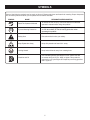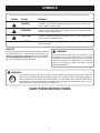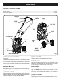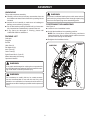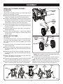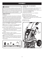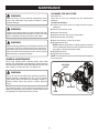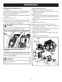
1
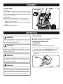
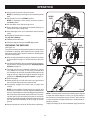
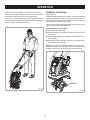
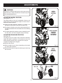
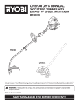
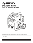
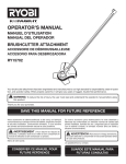
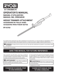
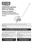
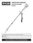
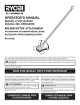
OPERATOR’S MANUAL CULTIVATOR RY60511B Your cultivator has been engineered and manufactured to our high standard for dependability, ease of operation, and operator safety. When properly cared for, it will give you years of rugged, trouble-free performance. WARNING: To reduce the risk of injury, the user must read and understand the operator’s manual before using this product. Thank you for your purchase. SAVE THIS MANUAL FOR FUTURE REFERENCE TABLE OF CONTENTS Introduction ..................................................................................................................................................................... 2 � General Safety Rules ....................................................................................................................................................... 3 � Specific Safety Rules....................................................................................................................................................... 4 � Symbols ........................................................................................................................................................................ 5-6 � Features ........................................................................................................................................................................... 7 � Assembly .................................................................................................................................................................... 8-11 � Operation .................................................................................................................................................................. 11-13 Adjustments................................................................................................................................................................... 14 � Maintenance ............................................................................................................................................................. 15-17 Troubleshooting ............................................................................................................................................................. 18 � Warranty ................................................................................................................................................................... 19-21 � Parts Ordering / Service ................................................................................................................................................ 22 INTRODUCTION This tool has many features for making its use more pleasant and enjoyable. Safety, performance, and dependability have been given top priority in the design of this product making it easy to maintain and operate. 2 GENERAL SAFETY RULES Do not operate the equipment while barefoot or when wearing sandals or similar lightweight footwear. Wear protective footwear that will protect your feet and improve your footing on slippery surfaces. WARNING! READ AND UNDERSTAND ALL INSTRUCTIONS. Failure to follow all instructions listed below, may result in electric shock, fire and/or serious personal injury. Do not operate the cultivator while under the influence of alcohol or drugs. SAVE THESE INSTRUCTIONS Do not put hands or feet near or under tines. Read the operator’s manual carefully. Be thoroughly familiar with the controls and the proper use of the equipment. Know how to stop the unit and disengage the controls quickly. Keep firm footing and balance. Do not overreach. Overreaching can result in loss of balance. Exercise caution to avoid slipping or falling. Never start or run the engine inside a closed area. Breathing exhaust fumes will kill you. Never allow children to operate the equipment. Never allow adults to operate the equipment without proper instruction. Never pick up or carry a machine while the engine is running. Wear eye protection that is marked to comply with ANSI Z87.1 standards as well as hearing protection when operating this unit. Use face mask if operation is dusty. Keep machine in good working condition. Check all nuts, bolts, and screws at frequent intervals for proper tightness to be sure the equipment is in safe working condition. Do not force tool. Use the correct tool for your application. The correct tool will do the job better and safer at the rate for which it is designed. Never store the machine with fuel in the fuel tank. Keep the unit free of grass, leaves, or grease to reduce the chance of a fire hazard. Wear heavy long pants, boots, and gloves. Do not wear loose fitting clothing, short pants, jewelry of any kind, or go barefoot. SERVICE Secure long hair so it is above shoulder level to prevent entanglement in any moving parts. Before cleaning, repairing, or inspecting, shut off the engine and make certain all moving parts have stopped. Disconnect the spark plug wire, and keep the wire away from the plug to prevent starting. Keep all bystanders, children, and pets at least 50 ft. away. Keep the area of operation clear of all persons, particularly small children, and pets. Service on the cultivator must be performed by qualified repair personnel only. Service or maintenance performed by unqualified personnel could result in injury to the user or damage to the product. Never operate the cultivator without good visibility. Thoroughly inspect the area where the equipment is to be used and remove all foreign objects. Use only identical replacement parts when servicing the cultivator. Use of unauthorized parts may create a risk of serious injury to the user, or damage to the product. Do not operate the machine without wearing adequate outer garments. Avoid loose garments or jewelry that could get caught in moving parts of the machine or its engine. 3 SPECIFIC SAFETY RULES Check damaged parts. Before further use of this cultivator, a guard or other part that is damaged should be carefully checked to determine that it will operate properly and perform its intended function. Check for alignment of moving parts, binding of moving parts, breakage of parts, mounting, and any other condition that may affect its operation. A guard or other part that is damaged should be properly repaired or replaced by an authorized service center unless otherwise indicated elsewhere in this manual. Do not use near underground electric cables, telephone lines, pipes, or hoses. If in doubt, contact your utility or telephone company to locate underground services. If the unit strikes a foreign object, stop the engine, disconnect the spark plug, thoroughly inspect the machine for any damage, and repair the damage before restarting and operating the machine. Never leave the operating position when the engine is running. Stop the engine and disconnect the spark plug before unclogging the tines and when making any repairs, adjustments, or inspections. REFUELING Fuel is highly flammable. Take precautions when using to reduce the chance of serious personal injury. Do not overload the machine capacity by cultivating too deep in a single pass or at too fast a rate. Store fuel in a cool, well-ventilated area, safely away from spark and/or flame-producing equipment. Stay alert. Watch what you are doing. Use common sense. Do not operate cultivator when you are tired. Store fuel in containers specifically designed for this purpose. Be aware that the equipment may unexpectedly bounce upward or jump forward if the tines should strike buried obstacles such as large stones, roots, or stumps. Only refuel outdoors and do not smoke while refueling. Add fuel before starting the engine. Never remove the cap of the fuel tank or add fuel while the engine is running or when the engine is hot. Never operate the equipment on a slope. Use extreme caution when pulling the machine towards you. If fuel is spilled, do not attempt to start the engine but move the machine away from the area of spillage and avoid creating any source of ignition until fuel vapors have dissipated. Start the engine carefully according to instructions from a normal operating position and with feet well away from the tines. Do not force cultivator. It will do the job better and with less likelihood of a risk of injury at the rate for which it was designed. Replace all fuel tank and container caps securely. When draining the fuel tank, use an approved fuel storage container while in a well-ventilated area. When not in use, cultivator should be stored indoors in a dry, locked up place — out of the reach of children. Save these instructions. Refer to them frequently and use them to instruct others who may use this cultivator. If you loan someone this unit, loan them these instructions also. Maintain cultivator with care. Keep tines clean for best performance and reduce the risk of injury. Follow instructions for lubrication and changing accessories. Inspect cultivator cord periodically and, if damaged, have it replaced. Keep handles dry, clean, and free from grease and oil. 4 SYMBOLS Some of the following symbols may be used on this tool. Please study them and learn their meaning. Proper interpretation of these symbols will allow you to operate the tool better and safer. SYMBOL 50' 15 m NAME DESIGNATION/EXPLANATION Read The Operator’s Manual To reduce the risk of injury, user must read and understand operator’s manual before using this product. Eye and Hearing Protection Always wear safety goggles, safety glasses with side shields, or a full face shield, as well as hearing protection when operating this product. Safety Alert Precautions that involve your safety. Keep Bystanders Away Keep all bystanders at least 50 ft. away. Cutting Hazard Keep feet and hands away from rotating tines. Gasoline and Oil Use unleaded gasoline intended for motor vehicle use with an octane rating of 87 [(R + M)/2] or higher. This product is powered by a 2-cycle engine and requires pre-mixing gasoline and 2-cycle oil. 5 SYMBOLS The following signal words and meanings are intended to explain the levels of risk associated with this product. SYMBOL SIGNAL MEANING DANGER: Indicates an imminently hazardous situation, which, if not avoided, will result in death or serious injury. WARNING: Indicates a potentially hazardous situation, which, if not avoided, could result in death or serious injury. CAUTION: Indicates a potentially hazardous situation, which, if not avoided, may result in minor or moderate injury. CAUTION: (Without Safety Alert Symbol) Indicates a situation that may result in property damage. SERVICE Servicing requires extreme care and knowledge and should be performed only by a qualified service technician. For service we suggest you return the product to your nearest AUTHORIZED SERVICE CENTER for repair. When servicing, use only identical replacement parts. WARNING: To avoid serious personal injury, do not attempt to use this product until you read thoroughly and understand completely the operator’s manual. If you do not understand the warnings and instructions in the operator’s manual, do not use this product. Call Ryobi customer service for assistance. WARNING: The operation of any power tool can result in foreign objects being thrown into your eyes, which can result in severe eye damage. Before beginning power tool operation, always wear safety goggles or safety glasses with side shields and, when needed, a full face shield. We recommend Wide Vision Safety Mask for use over eyeglasses or standard safety glasses with side shields. Always use eye protection which is marked to comply with ANSI Z87.1. SAVE THESE INSTRUCTIONS 6 FEATURES PRODUCT SPECIFICATIONS Engine Size ..................................................................................................................................................................25.4 cc Engine Output ..............................................................................................................................................................1.2 HP Sand Tank Capacity ..................................................................................................................................................... 13 lbs. THROTTLE LEVER RECOIL STARTER ENGINE SWITCH START LEVER FUEL TANK PRIMER BULB TINE SHIELD JUST ADD SAND™ DRAG BAR OUTER TINE INNER TINES HITCH PIN WHEEL ASSEMBLY ACCESSORY OUTER TINE Fig. 1 RECOIL STARTER KNOW YOUR CULTIVATOR See Figure 1. The safe use of this product requires an understanding of the information on the tool and in this operator’s manual as well as a knowledge of the project you are attempting. Before use of this product, familiarize yourself with all operating features and safety rules. The recoil starter is used for starting the engine. PRIMER BULB The primer bulb pumps fuel from the fuel tank to the carburetor. This is necessary only when starting a cold engine or after refueling an engine that has run out of fuel. ENGINE SWITCH START LEVER The engine switch controls the ignition system. The switch must be in the ON ( I ) position for the engine to start and run. To stop, place the switch in the OFF ( O ) position. The start lever opens and closes the choke valve in the carburetor. The START position enriches the fuel mixture for starting a cold engine. The RUN position provides the correct fuel mixture for normal operation after starting, or for restarting a warm engine. JUST ADD SAND™ Putting sand in the sand tank allows greater stability when operating the cultivator, and also gives added weight to the machine, allowing it to cultivate with less effort and vibration. THROTTLE LEVER The throttle lever controls the rotation speed of the tines. Completely engage the throttle lever while cultivating. 7 ASSEMBLY UNPACKING WARNING: This product requires assembly. To prevent accidental starting that could cause serious personal injury, always disconnect the engine spark plug wire from the spark plug when assembling parts. Carefully remove the tool and any accessories from the box. Make sure that all items listed in the packing list are included. Inspect the tool carefully to make sure no breakage or damage occurred during shipping. Do not discard the packing material until you have carefully inspected and satisfactorily operated the tool. If any parts are damaged or missing, please call 1-800-860-4050 for assistance. POSITIONING THE HANDLEBAR See Figure 2. Loosen the two handlebar knobs. Unfold the handlebar into operating position. NOTE: Do not use force. If there is binding, continue to loosen the knobs. Do not allow throttle cable to become pinched when raising the handlebar. PACKING LIST Cultivator Retighten the handlebar knobs. Drag Bar Pull Pin Hitch Pins (2) HANDLEBAR Felt Washers (2) HANDLEBAR KNOBS Inner Tines (2) Outer Tines (2) Ryobi Exact Mix 2-Cycle Oil Wheel Assembly (Accessory) Operator’s Manual WARNING: If any parts are damaged or missing do not operate this tool until the parts are replaced. Failure to heed this warning could result in serious personal injury. WARNING: Do not attempt to modify this tool or create accessories not recommended for use with this tool. Any such alteration or modification is misuse and could result in a hazardous condition leading to possible serious personal injury. Fig. 2 8 ASSEMBLY INSTALLING THE WHEEL ASSEMBLY ACCESSORY ADJUSTMENT KNOB See Figures 3 - 4. Use the wheel assembly accessory to transport the unit to and from the work area. To install: OPENING Raise the adjustment knob located at the back of the tine shield. Twist slightly to secure in the raised position. Insert the wheel assembly support rod into the opening beneath the adjustment knob. To place the wheels in a high position, insert the rod to the first hole. For a lower wheel position, insert the rod to the second hole. Rotate the adjustment knob in the opposite direction to return it to the seated position, which will secure the wheel assembly in place. Insert the drag bar into the open slot in the wheel assembly support rod. Insert pull pin through holes in support rod, passing through desired hole in drag bar, to secure drag bar at desired height. WHEEL ASSEMBLY SUPPORT ROD DRAG BAR Fig. 3 INSTALLING THE TINES WHEEL ASSEMBLY SUPPORT ROD See Figure 5. The cultivator has four tines —two inner tines labeled B and C, and two outer tines labeled A and D. For correct operation of the unit, the tines must be installed in the correct orientation. DRAG BAR PULL PIN Lean the unit back on its wheels so that the handlebar rests on the ground. Place tine C on the tine shaft to the left of the gear box. The stamped side of the tine should face away from the gear box. Place tine B on the tine shaft to the right of the gear box. The stamped side of the tine should face away from the gear box. Place a felt washer on each side of the tine shaft, and slide to rest against the inner tines. Fig. 4 NOTE: When installed correctly, the angled edge of the tine blades should face the ground. To secure the tines to the tine shaft, insert the hitch pin into the holes located on either side of the tine shaft. NOTE: The unit will not operate properly if the tines are installed incorrectly. If you notice a problem with the cultivating operation of the unit, check for proper tine positioning. Place the outer tine labeled D on the left side of the tine shaft. The stamped side should face in toward tine C. Place the outer tine labeled A on the right side of the tine shaft. The stamped side should face in toward tine B. FELT FLAT EDGE WASHER GEAR BOX FELT WASHER TINE A TINE D HITCH PIN ANGLED EDGE TINE C TINE SHAFT 9 TINE B HITCH PIN Fig. 5 ASSEMBLY ADDING FUEL TO CULTIVATOR WARNING: See Figure 7. When adding fuel to the cultivator, make sure the unit is sitting on level ground and that the engine is not hot. Fuel only with recommended 50:1 mixture of gasoline and oil as described in Mixing the Fuel. To add fuel to the cultivator: Clean area around fuel tank cap, if necessary. Gasoline and its vapors are highly flammable and explosive. To prevent serious personal injury and property damage, handle it with care. Keep away from ignition sources, handle outdoors only, do not smoke while mixing gasoline and oil together; and wipe up spills immediately. MIXING THE FUEL Remove the fuel tank cap. See Figure 6. The cultivator is powered by a two-stroke, air-cooled engine and requires a fuel mixture of gasoline and 2-cycle fuel oil. NOTE: Always mix two-cycle engine oil like Ryobi’s Exact Mix Semi Synthetic Oil with gasoline before fueling the unit. Running the cultivator on gasoline alone will ruin the engine. Use a mixture of 50 parts unleaded regular gasoline and 1 part two-stroke engine oil (50:1). Use branded 87 octane (R+M+2) unleaded gasoline or gasohol (maximum 10% ethyl alcohol, or 15% MTBE, no methyl alcohol.) NOTE: Always mix oil and gas in the proper proportions: 2.6 ounces of oil to one gallon of unleaded gasoline. To mix the oil and fuel together for use: Pour 1/2 gallon of gasoline into a clean gas can or other container approved for fuel storage. Do not mix the fuel and oil directly in the cultivator’s fuel tank. Insert a clean funnel into the fuel tank. Slowly pour gasoline/oil mixture into fuel tank. NOTE: Fill tank no higher than 1/2 in. from top to allow for gasoline expansion. Reinstall fuel cap. Clean up any spills. Add 2.6 ounces of two-cycle engine oil to the gasoline mixture. FUEL TANK CAP Add the remaining 1/2 gallon of gasoline. Close the container holding the gas/oil mix and swirl the can to blend contents together. NOTE: Do not mix more than you will use in a month, and shake the container to blend thoroughly before each use. Using an old fuel mixture can cause starting difficulty or engine damage. 1 Gallon + 2.6 oz. = 50:1 Fig. 7 Fig. 6 10 ASSEMBLY ADDING SAND JUST ADD SAND™ LID See Figure 8. The cultivator is equipped with a Just Add Sand™ weight system, which improves the stability of the unit during operation. The added weight of the sand also helps you work with less effort and vibration. To add sand: Lift the lid of the Just Add Sand™ tank and remove. Pour dry sand into the tank. The tank will hold approximately 13 pounds of sand. NOTE: Be careful not to pour sand into or onto the engine housing. Replace Just Add Sand™ lid. Fig. 8 OPERATION APPLICATIONS WARNING: Breaking up garden soil to prepare seed bed for planting Shallow cultivating to remove weeds Do not allow familiarity with tools to make you careless. Remember that a careless fraction of a second is sufficient to inflict serious injury. STARTING/STOPPING THE CULTIVATOR See Figures 9 - 12. To start an engine that is cold or has run dry: Fill the fuel tank, if necessary. Always use the proper oil/gasoline mixture. See Mixing the Fuel on page 10. WARNING: Always wear safety goggles or safety glasses with side shields when operating tools. Failure to do so could result in objects being thrown into your eyes, resulting in possible serious injury. Place the engine switch in the RUN ( | ) position. NOTE: Do not engage the throttle lever during the starting process. WARNING: ENGINE SWITCH Do not use any attachments or accessories not recommended by the manufacturer of this tool. The use of attachments or accessories not recommended can result in serious personal injury. WARNING: Fig. 9 Do not allow hands, feet, or any other part of the body or clothing near the rotating tines or any other moving part. The tines begin to rotate forward once the engine is started and the throttle lever is depressed. The tines continue to rotate until the throttle lever is released. Failure to avoid contact could cause serious personal injury. 11 OPERATION Slowly push the primer bulb seven times. NOTE: If restarting a warm engine, do not push the primer bulb. PRIMER BULB Set the start lever to the START position. NOTE: If restarting a warm engine, leave the choke in the RUN position. Pull the starter cord until the engine runs. Return the starter cord gently to the starter housing. Do not allow the rope to snap back. Allow the engine to run for 15 seconds to warm up before using. Fig. 10 Engage the throttle lever to operate. To stop the cultivator: START LEVER START LEVER Release the throttle lever. Move the engine switch to the OFF ( O ) position. START POSITION PREPARING THE SEED BED See Figure 13. The cultivator can be used to break up garden soil and prepare a seedbed for planting. Plan ahead to leave enough room between the seed rows to allow for machine cultivating after the plants have grown. With the wheel assembly accessory installed in position A as described on page 14, roll the machine to the work area. RUN POSITION Fig. 11 For general cultivating, remove or adjust the wheel assembly accessory using the guidelines in Adjusting Wheel Position on page 14. The drag bar has two installation positions to choose from. Based on the type of soil being cultivated and soil conditions at the time, the appropriate height of the drag bar will vary. Adjust the drag bar position using the guidelines in Adjusting Drag Bar Position on page 14. RECOIL STARTER Start the engine. Stand behind the unit with the tines on the ground and the work area clean and free of obstructions. Completely engage the throttle lever to begin tine rotation. NOTE: If the machine moves forward too quickly and wheels are in position A or B with drag bar installed, push down on the handlebar to allow the drag bar to penetrate the soil and slow the forward motion of the unit. The rotating tines help to pull the machine forward, so use slower speeds and a shallow depth setting when learning to use the unit and when cultivating on hard, rough, or uneven ground. Fig. 12 NOTE: Several passes over the same path may be required to reach the desired depth. Do not try to dig too deeply in the first pass. If the machine jumps or bucks, allow the unit to move forward at a slightly faster rate or install wheel assembly accessory. To dig more deeply, lift up on the handlebar. Apply downward Always operate the unit at full throttle when cultivating. 12 OPERATION GENERAL CULTIVATING pressure on the handlebar for more shallow cultivating. If the machine stays and digs in one spot, try rocking the unit from side to side to start it moving forward again. If the soil is very hard, water a few days before cultivating. Avoid working the soil when soggy or wet. Wait a day or two after heavy rain for the ground to dry. See Figure 14. Shallow cultivating less than 2 in. deep can be used to disrupt weeds and aerate soil, without injuring nearby plant roots. It should be done often so that weeds do not grow large and cause tangling in the tines of the unit. The two outer tine blades can be removed from the unit to allow a more narrow cultivating width. To remove the two outer tines: Disconnect the spark plug. Remove the hitch pins from the holes on the ends of the tine shaft. Remove the outside tine blades and felt washers from the tine shaft. Place hitch pins in the holes that were uncovered when felt washers were removed. NOTE: The unit will not operate properly if the tines are installed incorrectly. If you notice a problem with the cultivating operation of the unit, check for proper tine positioning. HITCH PIN Fig. 13 Fig. 14 13 ADJUSTMENTS WARNING: WHEEL SUPPORT POSITION A To prevent accidental starting that could cause serious personal injury, always disconnect the spark plug wire when making adjustments. ADJUSTING WHEEL POSITION See Figures 15 - 17. The wheel position of the unit is adjustable. Holes on the wheel support rod offer different heights to choose from in both the A and B positions. Install the wheel assembly accessory in position A to transport the cultivator to and from the work area. Fig. 15 For general cultivating, remove the wheel assembly to allow deep penetration of the tine blades into the cultivating surface. WHEEL ASSEMBLY ACCESSORY REMOVED FOR GENERAL CULTIVATING The wheel assembly accessory may be installed in position B to allow use of the drag bar during cultivating. ADJUSTING DRAG BAR POSITION See Figure 18. The drag bar may be used to help control the cultivator’s speed and depth of operation. It is located in a slot on the wheel assembly support and is secured with a pull pin. To adjust the height of the drag bar: Remove the pull pin. Fig. 16 Shift the drag bar up or down, depending on the depth you are trying to achieve. Reinsert the pull pin through the wheel support and drag bar to secure. WHEEL SUPPORT POSITION B Fig. 17 PULL PIN DRAG BAR Fig. 18 14 MAINTENANCE CLEANING THE AIR FILTER WARNING: See Figure 19. Cean the air filter as indicated by the maintenance schedule. To clean the air filter: Loosen the air filter cover by turning the knob counterclockwise. When servicing, use only identical replacement parts. Use of any other parts may create a hazard or cause product damage. WARNING: Remove the air filter cover. Always wear safety goggles or safety glasses with side shields during power tool operation or when blowing dust. If operation is dusty, also wear a dust mask. Remove the air filter. Wash the air filter with warm, soapy water. Rinse and let dry completely. Work two drops of oil into the air filter. Reinstall the air filter. NOTE: Make sure the filter is seated properly inside the cover. Installing the filter incorrectly will allow dirt to enter the engine, causing rapid engine wear. Reinstall the cover. Tighten knob to secure. WARNING: Before inspecting, cleaning or servicing the machine, shut off engine, wait for all moving parts to stop, and disconnect spark plug wire and move it away from spark plug. Failure to follow these instructions can result in serious personal injury or property damage. NOTE: For best performance, the air filter should be replaced once each year. GENERAL MAINTENANCE Avoid using solvents when cleaning plastic parts. Most plastics are susceptible to damage from various types of commercial solvents and may be damaged by their use. Use clean cloths to remove dirt, dust, oil, grease, etc. AIR FILTER COVER WARNING: Do not at any time let brake fluids, gasoline, petroleumbased products, penetrating oils, etc., come in contact with plastic parts. Chemicals can damage, weaken or destroy plastic which may result in serious personal injury. AIR FILTER Only the parts shown on the parts list are intended to be repaired or replaced by the customer. All other parts should be replaced at an Authorized Service Center. KNOB 15 Fig. 19 MAINTENANCE REPLACING THE SPARK PLUG To replace the spark arrestor: Remove the five screws that hold the cover. See Figure 20. The cultivator uses Champion RCJ-4Y or NGK BPMR7A spark plug. Use an exact replacement and replace annually. Remove the spark plug boot. Note: Removing these screws requires the use of a T20 and T25 torx screwdriver. Remove the cover. Loosen the spark plug by turning it counterclockwise with a socket. Remove the muffler assembly and muffler gasket. It may be necessary to work the muffler assembly free from the muffler gasket. Remove the spark plug. Remove the three screws that hold the plates on the muffler. Hand thread the new spark plug, turning it clockwise. Tighten with a socket and torque to 170 in. lb. minimum, 190 in. lb. maximum. Do not overtighten. Remove the spark arrester. Replace the old spark arrester with the new one. Reassemble the muffler by reinstalling the plates and tightening the three screws. CAUTION Be careful not to cross-thread the spark plug. Crossthreading will seriously damage the product. Reassemble the muffler and muffler cover and attach to the muffler gasket with the two screws. Reinsert the muffler assembly. Reinstall the cover on the tool and fasten with the five screws. SPARK PLUG Note: Do not overtighten screws. COVER SCREW(S) Fig. 20 REPLACING THE SPARK ARRESTOR See figure 21. The muffler is equipped with a spark arrestor screen inside muffler body. After extended use the screen can become dirty and may need to be replaced. If replacement is necessary, use part number 000998216. MUFFLER COVER MUFFLER GASKET WARNING: SPARK ARRESTER MUFFLER PLATE To avoid a fire hazard, never run the cultivator without the spark arrestor in place. SCREW(S) 16 SCREW(S) Fig. 20 MAINTENANCE CLEANING THE EXHAUST PORT AND MUFFLER Air Filter: Clean the air filter as previously described. Cultivator Body: Clean dirt, grass, and other materials from the entire unit. Wipe the tines with oil or spray them with silicone lubricant to prevent rusting. Oil the throttle cable and all visible moving parts. Do not remove the engine cover. Depending on the type of fuel used, the type and amount of oil used, and/or your operating conditions, the exhaust port and muffler may become blocked with carbon deposits. If you notice a power loss with your gas powered tool, a qualified service technician will need to remove these deposits to restore performance. STORING THE CULTIVATOR Order new parts to replace any that are badly worn or broken. The following steps should be taken before storing the cultivator for the season. Fuel Tank: Drain the fuel tank completely. Even under ideal conditions, stored fuel containing ethanol or MTBE can start to go stale in 30 days. Stale fuel has a high gum content and can clog the carburetor and restrict fuel flow. The fuel tank should also be drained if the cultivator will not be used for more than two weeks. Restart the engine to make sure no fuel is left in the carburetor. Run the engine until it stops. This helps prevent gum deposits from forming inside the carburetor and possible engine damage. Spark Plug: Disconnect spark plug wire and remove the spark plug. Pour a teaspoon of clean, air-cooled, 2-cycle oil through the spark-plug hole into the combustion chamber. Leaving the spark plug out, pull the starter cord two or three times to coat the inside of the cylinder wall. Inspect spark plug and clean or replace, as necessary. Reinstall the spark plug, but leave the spark plug wire disconnected. Store in an upright position in a clean, dry place. Store with the handles in the extended position, or loosen handle knobs and fold handles down. Do not allow throttle cable to become pinched when lowering the handlebar. Properly dispose of any leftover fuel. PREPARING FOR USE AFTER STORAGE The following steps should be taken before using the cultivator after it has been stored. Unfold the handles into the upright position and secure by tightening handlebar knobs. Do not allow throttle cable to become pinched when raising the handlebar. Pull the starter cord three or four times to clean oil from the combustion chamber. Remove spark plug from the cylinder. Wipe oil from the spark plug and return it to the cylinder. Reconnect spark plug wire. Follow the steps on pages 10 - 12 to refuel and restart the cultivator. 17 TROUBLESHOOTING PROBLEM CAUSE Engine fails to start. REMEDY Engine switch is in the off position. Move switch to start. No fuel in tank. Fill tank. Spark plug shorted or fouled. Replace spark plug. Spark plug is broken (cracked porcelain or electrodes broken). Replace spark plug. Ignition lead wire shorted, broken, or disconnected from spark plug. Replace lead wire or attach to spark plug. Ignition inoperative. Contact authorized service center. Water in gasoline or stale fuel mixture. Drain entire system and refill with fresh fuel. Engine hard to start. Too much oil in fuel mixture. Drain and refill with correct mixture. Engine is under or over choked. Adjust choke as necessary. Weak spark at spark plug. Contact authorized service center. Engine lacks power. Air filter clogged. Clean or replace air filter. Engine overheats. Insufficient oil in fuel mixture. Mix fuel as described in starting instructions. CALL US FIRST CALL 1-800-860-40 50 For any questions about operating or maintaining your product, call the Ryobi® Help Line! Your product has been fully tested prior to shipment to ensure your complete satisfaction. 18 WARRANTY LIMITED WARRANTY STATEMENT Techtronic Industries North America, Inc., warrants to the original retail purchaser that this RYOBI® brand outdoor product is free from defect in material and workmanship and agrees to repair or replace, at Techtronic Industries North America, Inc.’s, discretion, any defective product free of charge within these time periods from the date of purchase. Two years if the product is used for personal, family or household use; B. Wear items – Bump Knobs, Outer Spools, Cutting Lines, Inner Reels, Starter Pulleys, Starter Ropes, Drive Belts, Tines, Felt Washers, Hitch Pins, Mulching Blades, Blower Fans, Blower and Vacuum Tubes, Vacuum Bag and Straps, Guide Bars, Saw Chains 90 days, if used for any other purpose, such as commercial or rental. ALL IMPLIED WARRANTIES ARE LIMITED IN DURATION TO THE STATED WARRANTY PERIOD. ACCORDINGLY, ANY SUCH IMPLIED WARRANTIES INCLUDING MERCHANTABILITY, FITNESS FOR A PARTICULAR PURPOSE, OR OTHERWISE, ARE DISCLAIMED IN THEIR ENTIRETY AFTER THE EXPIRATION OF THE APPROPRIATE TWO-YEAR, ONE-YEAR, OR NINETYDAY WARRANTY PERIOD. TECHTRONIC INDUSTRIES NORTH AMERICA, INC.’S, OBLIGATION UNDER THIS WARRANTY IS STRICTLY AND EXCLUSIVELY LIMITED TO THE REPAIR OR REPLACEMENT OF DEFECTIVE PARTS AND TECHTRONIC INDUSTRIES NORTH AMERICA, INC., DOES NOT ASSUME OR AUTHORIZE ANYONE TO ASSUME FOR THEM ANY OTHER OBLIGATION. SOME STATES DO NOT ALLOW LIMITATIONS ON HOW LONG AN IMPLIED WARRANTY LASTS, SO THE ABOVE LIMITATION MAY NOT APPLY TO YOU. TECHTRONIC INDUSTRIES NORTH AMERICA, INC., ASSUMES NO RESPONSIBILITY FOR INCIDENTAL, CONSEQUENTIAL, OR OTHER DAMAGES INCLUDING, BUT NOT LIMITED TO, EXPENSE OF RETURNING THE PRODUCT TO AN AUTHORIZED RYOBI SERVICE CENTER AND EXPENSE OF DELIVERING IT BACK TO THE OWNER, MECHANIC’S TRAVEL TIME, TELEPHONE OR TELEGRAM CHARGES, RENTAL OF A LIKE PRODUCT DURING THE TIME WARRANTY SERVICE IS BEING PERFORMED, TRAVEL, LOSS OR DAMAGE TO PERSONAL PROPERTY, LOSS OF REVENUE, LOSS OF USE OF THE PRODUCT, LOSS OF TIME, OR INCONVENIENCE. SOME STATES DO NOT ALLOW THE EXCLUSION OR LIMITATION OF INCIDENTAL OR CONSEQUENTIAL DAMAGES, SO THE ABOVE LIMITATION OR EXCLUSION MAY NOT APPLY TO YOU. This warranty gives you specific legal rights, and you may also have other rights which vary from state to state. This warranty applies to all RYOBI® brand outdoor products manufactured by or for Techtronic Industries North America, Inc., and sold in the United States and Canada. To locate your nearest Authorized Ryobi Service Center, dial 1-800-860-4050. Techtronic Industries North America, Inc., reserves the right to change or improve the design of any RYOBI® brand outdoor product without assuming any obligation to modify any product previously manufactured. This warranty extends to the original retail purchaser only and commences on the date of the original retail purchase. Any part of this product found in the reasonable judgment of Techtronic Industries North America, Inc. to be defective in material or workmanship will be repaired or replaced without charge for parts and labor by an authorized service center for RYOBI® brand outdoor products (Authorized Ryobi Service Center). The product, including any defective part, must be returned to an authorized RYOBI service center within the warranty period. The expense of delivering the product to the service center for warranty work and the expense of returning it back to the owner after repair or replacement will be paid by the owner. Techtronic Industries North America, Inc.’s, responsibility in respect to claims is limited to making the required repairs or replacements and no claim of breach of warranty shall be cause for cancellation or rescission of the contract of sale of any RYOBI® brand outdoor product. Proof of purchase will be required by the dealer to substantiate any warranty claim. All warranty work must be performed by an authorized service dealer. This warranty is limited to ninety (90) days from the date of original retail purchase for any RYOBI® brand outdoor product that is used for rental or commercial purposes, or any other income-producing purpose. This warranty does not cover any product that has been subject to misuse, neglect, negligence, or accident, or that has been operated in any way contrary to the operating instructions as specified in this operator’s manual. This warranty does not apply to any damage to the product that is the result of improper maintenance or to any product that has been altered or modified. The warranty does not extend to repairs made necessary by normal wear or by the use of parts or accessories which are either incompatible with the RYOBI® brand outdoor product or adversely affect its operation, performance, or durability. In addition, this warranty does not cover: A. Tune-ups – Spark Plugs, Carburetor, Carburetor Adjustments, Ignition, Filters 19 WARRANTY THE FOLLOWING CALIFORNIA AIR RESOURCES BOARD (CARB) STATEMENT ONLY APPLIES TO MODEL NUMBERS REQUIRED TO MEET THE CARB REQUIREMENTS. TECHTRONIC INDUSTRIES NORTH AMERICA, INC., LIMITED WARRANTY FEDERAL AND CALIFORNIA EMISSION CONTROL SYSTEMS NON-ROAD AND SMALL OFF-ROAD ENGINES The U.S. Environmental Protection Agency (EPA), the California Air Resources Board (CARB), and Techtronic Industries North America, Inc., are pleased to explain the Emission Control System Warranty on your non-road or small off-road engine. In California, new small off-road engines must be designed, built, and equipped to meet the state’s stringent anti-smog standards. In other states, new 2000 and later model year non-road engines must be designed, built, and equipped at the time of sale to meet the U.S. EPA regulations for small non-road engines. The non-road engine must be free from defects in materials and workmanship which cause it to fail to conform with U.S. EPA standards for the first two years of engine use from the date of sale to the ultimate purchaser. Techtronic Industries North America, Inc., must warrant the emission control system on your non-road or small off-road engine for the period of time listed above provided there has been no abuse, neglect, or improper maintenance of your non-road or small off-road engine. Your emission control system may include parts such as the carburetor or fuel injection system, the ignition system, and the catalytic converter. Also included may be hoses, belts and connectors, and other emission-related assemblies. Where a warrantable condition exists, Techtronic Industries North America, Inc., will repair your non-road or small off-road engine at no cost to you, including diagnosis (if the diagnostic work is performed at an authorized service center for RYOBI® brand outdoor products), parts, and labor. MANUFACTURER’S WARRANTY COVERAGE: The 1995 and later small off-road engines are warranted for two years in California. In other states, 1997 and later model year non-road engines are also warranted for two years. If any emission-related part on your engine is defective, the part will be repaired or replaced by Techtronic Industries North America, Inc., free of charge. OWNER’S WARRANTY RESPONSIBILITIES (a) As the non-road or small off-road engine owner, you are responsible for the performance of required maintenance listed in your operator’s manual. Techtronic Industries North America, Inc., recommends that you retain all receipts covering maintenance on your non-road or small off-road engine, but Techtronic Industries North America, Inc., cannot deny warranty solely for the lack of receipts or for your failure to ensure the performance of all scheduled maintenance. Any replacement part or service that is equivalent in performance and durability may be used in non-warranty maintenance or repairs, and shall not reduce the warranty obligations of the engine manufacturer. (b) As the non-road or small off-road engine owner, you should be aware, however, that Techtronic Industries North America, Inc., may deny you warranty coverage if your non-road or small off-road engine or a part has failed due to abuse, neglect, improper maintenance, or unapproved modifications. (c) You are responsible for presenting your non-road or small off-road engine to an authorized service dealer as soon as a problem exists. The warranty repairs should be completed in a reasonable amount of time, not to exceed 30 days. If you have any questions regarding your warranty rights and responsibilities, you should contact a Techtronic Industries North America, Inc., Customer Representative at 1-800-860-4050. COVERAGE: Techtronic Industries North America, Inc., warrants to the ultimate purchaser and each subsequent purchaser that your non-road or small off-road engine will be designed, built, and equipped at the time of sale, to meet all applicable regulations. Techtronic Industries North America, Inc., also warrants to the initial purchaser and each subsequent purchaser that your non-road or small off-road engine is free from defects in materials and workmanship which cause the engine to fail to conform with applicable regulations for a period of two years. The 1995 and later small off-road engines are warranted for two years in California. In all other states for 1997 and later model years, EPA requires manufacturers to warrant non-road engines for two years. These warranty periods will begin on the date the non-road or small off-road engine is purchased by the initial purchaser. If any emission-related part on your engine is defective, the part will be replaced by Techtronic Industries North America, Inc., at no cost to the owner. Techtronic Industries North America, Inc., shall remedy warranty defects at any authorized RYOBI engine dealer or warranty station. Any authorized work done at an authorized dealer or warranty station shall be free of charge to the owner if such work determines that a warranted part is defective. Any manufacturer-approved or equivalent replacement part may be used for any warranty maintenance or repairs on emission-related parts, and must be provided free of charge to the owner if the part is still under warranty. Techtronics North America, Inc., is liable for damages to other engine components caused by the failure of a warranted part still under warranty. The California Air Resources Board’s Emission Warranty Parts List specifically defines the emission-related warranted parts. (EPA’s regulations do not include a parts list, but EPA considers emission-related warranted parts to include all the parts listed below.) These warranted parts are: Carburetor, Spark Plug, Ignition, Air Filter, and Fuel Filter. MAINTENANCE REQUIREMENTS The owner is responsible for the performance of the required maintenance as defined by Techtronic Industries North America, Inc., in the operator’s manual. LIMITATIONS The Emission Control Systems Warranty shall not cover any of the following: (a) repair or replacement required because of misuse or neglect, lack of required maintenance, repairs improperly performed, or replacements not conforming to Techtronic Industries North America, Inc., specifications that adversely affect performance and/or durability, and alterations or modifications not recommended or approved in writing by Techtronic Industries North America, Inc., and (b) replacement of parts and other services and adjustments necessary for required maintenance at and after the first scheduled replacement point. The Emissions Compliance Period referred to on the Emissions Compliance label indicates the number of operating hours for which the engine has been shown to meet Federal emission requirements. Category C=50 hours, B=125 hours, and A=300 hours. 20 WARRANTY Emissions Parts EMISSIONS MAINTENANCE SCHEDULE AND WARRANTED PARTS LIST Inspect Before Clean Every Replace Every Clean Every Each Use 5 Hours 25 Hours or Yearly 25 Hours or Yearly AIR FILTER ASSY INCLUDES: FILTER................................................................................ X ........................................... X SPARK SCREEN ............................................................................................................................................................... X CARBURETOR ASSY INCLUDES: HEAT DAM ................................x GASKETS..................................x FUEL TANK ASSY INCLUDES: FUEL LINES ............................. X FUEL CAP ................................ X FUEL FILTER .............................x IGNITION ASSY INCLUDES: SPARK PLUG ................................................................................................................................................................ X ALL EMISSIONS-RELATED PARTS ARE WARRANTED FOR TWO YEARS, OR FOR THE PERIOD OF TIME PRIOR TO THE PARTS’ FIRST SCHEDULED REPLACEMENT, WHICHEVER COMES FIRST. 21 OPERATOR’S MANUAL CULTIVATOR RY60511B WARNING: The engine exhaust from this product contains chemicals known to the State of California to cause cancer, birth defects, or other reproductive harm. CALIFORNIA PROPOSITION 65 • SERVICE Now that you have purchased your tool, should a need ever exist for repair parts or service, simply contact your nearest Authorized Service Center. Be sure to provide all pertinent facts when you call or visit. Please call 1-800-860-4050 for your nearest Authorized Service Center. You can also check our web site at www.ryobitools.com for a complete list of Authorized Service Centers. • MODEL NO. AND SERIAL NO. The model number of this tool will be found on a plate attached to the motor housing. Please record the model number and serial number in the space provided below. • HOW TO ORDER REPAIR PARTS When ordering repair parts, always give the following information: • MODEL NUMBER • SERIAL NUMBER RY60511B Ryobi® is a registered trademark of Ryobi Limited used under license. TECHTRONIC INDUSTRIES NORTH AMERICA, INC. 1428 Pearman Dairy Road Anderson, SC 29625 Phone 1-800-860-4050 www.ryobitools.com 983000-886 12-19-05 (REV:00)