Download RUGGEDCOM ROS

Transcript
Preface
RUGGEDCOM ROS
v3.12
Introduction
1
Administration
2
Ethernet Ports
3
Ethernet Statistics
4
Link Aggregation
5
Spanning Tree
6
VLANs
7
Port Security
8
Classes of Service
9
Multicast Filtering
10
MAC Address Tables
11
Network Discovery
12
Diagnostics
13
Firmware Upgrade and
Configuration Management
14
User Guide
For RSG2300, RSG2300P
2/2014
RC1091-EN-01
RUGGEDCOM ROS
User Guide
Copyright © 2014 Siemens AG
All rights reserved. Dissemination or reproduction of this document, or evaluation and communication of its contents, is not authorized
except where expressly permitted. Violations are liable for damages. All rights reserved, particularly for the purposes of patent application or
trademark registration.
This document contains proprietary information, which is protected by copyright. All rights are reserved. No part of this document may be
photocopied, reproduced or translated to another language without the prior written consent of Siemens AG.
Disclaimer Of Liability
Siemens has verified the contents of this manual against the hardware and/or software described. However, deviations between the product
and the documentation may exist.
Siemens shall not be liable for any errors or omissions contained herein or for consequential damages in connection with the furnishing,
performance, or use of this material.
The information given in this document is reviewed regularly and any necessary corrections will be included in subsequent editions. We
appreciate any suggested improvements. We reserve the right to make technical improvements without notice.
Registered Trademarks
ROX™, Rugged Operating System On Linux™, CrossBow™ and eLAN™ are trademarks of Siemens AG. ROS® is a registered trademark of
Siemens AG.
Other designations in this manual might be trademarks whose use by third parties for their own purposes would infringe the rights of the
owner.
Third Party Copyrights
Siemens recognizes the following third party copyrights:
• Copyright © 2004 GoAhead Software, Inc. All Rights Reserved.
Security Information
Siemens provides products and solutions with industrial security functions that support the secure operation of plants, machines, equipment
and/or networks. They are important components in a holistic industrial security concept. With this in mind, Siemens ’ products and solutions
undergo continuous development. Siemens recommends strongly that you regularly check for product updates.
For the secure operation of Siemens products and solutions, it is necessary to take suitable preventive action (e.g. cell protection concept)
and integrate each component into a holistic, state-of-the-art industrial security concept. Third-party products that may be in use should also
be considered. For more information about industrial security, visit http://www.siemens.com/industrialsecurity.
To stay informed about product updates as they occur, sign up for a product-specific newsletter. For more information, visit http://
support.automation.siemens.com.
Warranty
Refer to the License Agreement for the applicable warranty terms and conditions, if any.
For warranty details, visit www.siemens.com/ruggedcom or contact a Siemens customer service representative.
Contacting Siemens
ii
Address
Telephone
E-mail
Siemens AG
Industry Sector
300 Applewood Crescent
Concord, Ontario
Canada, L4K 5C7
Toll-free: 1 888 264 0006
Tel: +1 905 856 5288
Fax: +1 905 856 1995
[email protected]
Web
www.siemens.com/ruggedcom
RUGGEDCOM ROS
User Guide
Table of Contents
Table of Contents
Preface ................................................................................................................
xi
About This Guide ............................................................................................................................... xi
Conventions ............................................................................................................................... xi
Alerts ................................................................................................................................. xi
CLI Command Syntax ........................................................................................................ xii
Related Documents .................................................................................................................... xii
System Requirements ........................................................................................................................ xii
Accessing Documentation .................................................................................................................. xiii
Application Notes .............................................................................................................................. xiii
Training ............................................................................................................................................ xiii
Customer Support ............................................................................................................................. xiii
Chapter 1
Introduction ..........................................................................................................
1
1.1 Security Considerations ................................................................................................................ 1
1.1.1 Security Recommendations ................................................................................................ 1
1.1.2 Key Files .......................................................................................................................... 2
1.1.2.1 SSL Certificates ...................................................................................................... 3
1.1.2.2 SSH Key Pairs ....................................................................................................... 4
1.1.3 Bootloader Considerations ................................................................................................. 6
1.2 SNMP MIB Support ...................................................................................................................... 6
1.2.1 Standard MIBs .................................................................................................................. 6
1.2.2 Siemens Proprietary MIBs ................................................................................................. 7
1.2.3 Siemens Supported Agent Capabilities MIBs ....................................................................... 8
1.3 SNMP Trap Summary ................................................................................................................ 10
1.4 Available Services by Port .......................................................................................................... 11
1.5 ModBus Management Support and Memory Map ......................................................................... 13
1.5.1 Modbus Memory Map ...................................................................................................... 14
1.5.1.1 Text ...................................................................................................................... 19
1.5.1.2 Cmd ..................................................................................................................... 19
1.5.1.3 Uint16 .................................................................................................................. 20
1.5.1.4 Uint32 .................................................................................................................. 20
1.5.1.5 PortCmd ............................................................................................................... 20
1.5.1.6 Alarm ................................................................................................................... 21
1.5.1.7 PSStatusCmd ....................................................................................................... 21
iii
Table of Contents
RUGGEDCOM ROS
User Guide
1.5.1.8 TruthValue ............................................................................................................ 22
1.6 Command Line Listing ................................................................................................................ 22
1.7 Using the CLI Shell .................................................................................................................... 25
1.7.1 Summary Of CLI Commands Available in ROS ................................................................. 26
1.7.2 Obtaining Help For A Command ....................................................................................... 26
1.7.3 Viewing Files ................................................................................................................... 26
1.7.3.1 Listing Files .......................................................................................................... 26
1.7.3.2 Viewing and Clearing Log Files ............................................................................. 27
1.7.4 Managing the Flash Filesystem ........................................................................................ 27
1.7.4.1 Flash Filesystem Memory Mapping ........................................................................ 28
1.7.4.2 Obtaining Information On a Particular File .............................................................. 28
1.7.4.3 Defragmenting the Flash Filesystem ...................................................................... 29
1.7.5 Pinging a Remote Device ................................................................................................ 29
1.7.6 Tracing Events ................................................................................................................ 30
1.7.6.1 Enabling Trace ..................................................................................................... 30
1.7.6.2 Starting Trace ....................................................................................................... 31
1.7.7 Viewing DHCP Learned Information .................................................................................. 32
1.7.8 Executing Commands Remotely Through RSH .................................................................. 32
1.7.9 Resetting the Device ....................................................................................................... 32
Chapter 2
Administration ....................................................................................................
33
2.1 The ROS User Interface ............................................................................................................. 33
2.1.1 Using the RS232 Port to Access the User Interface ........................................................... 33
2.1.2 The Structure of the User Interface ................................................................................... 34
2.1.3 Making Configuration Changes ......................................................................................... 35
2.1.4 Updates Occur In Real Time ............................................................................................ 35
2.1.5 Alarm Indications Are Provided ........................................................................................ 35
2.1.6 The CLI Shell .................................................................................................................. 35
2.2 The ROS Secure Shell Server .................................................................................................... 36
2.2.1 Using a Secure Shell to Access the User Interface ............................................................ 36
2.2.2 Using a Secure Shell to Transfer Files .............................................................................. 36
2.3 The ROS Web Server Interface .................................................................................................. 37
2.3.1 Using a Web Browser to Access the Web Interface ........................................................... 37
2.3.2 Customizing the Login Page ............................................................................................ 38
2.3.3 The Structure of the Web Interface ................................................................................... 38
2.3.4 Making Configuration Changes ......................................................................................... 39
2.3.5 Updating Statistics Displays ............................................................................................. 39
2.4 Administration Menu ................................................................................................................... 39
2.5 IP Interfaces .............................................................................................................................. 40
2.6 IP Gateways .............................................................................................................................. 42
iv
RUGGEDCOM ROS
User Guide
Table of Contents
2.7 IP Services ................................................................................................................................ 43
2.8 Data Storage ............................................................................................................................. 45
2.9 System Identification .................................................................................................................. 46
2.10 Passwords ............................................................................................................................... 46
2.11 System Time Management ........................................................................................................ 49
2.11.1 Configuring Time and Date ............................................................................................. 49
2.11.2 Configuring NTP Service ................................................................................................ 51
2.12 SNMP Management ................................................................................................................. 52
2.12.1 SNMP Users ................................................................................................................. 52
2.12.2 SNMP Security to Group Maps ....................................................................................... 54
2.12.3 SNMP Access ............................................................................................................... 55
2.13 RADIUS ................................................................................................................................... 56
2.13.1 RADIUS overview .......................................................................................................... 57
2.13.2 User Login Authentication and Authorization .................................................................... 57
2.13.3 802.1X Authentication .................................................................................................... 58
2.13.4 RADIUS Server Configuration ......................................................................................... 59
2.14 TACACS+ ................................................................................................................................ 60
2.14.1 User Login Authentication and Authorization .................................................................... 60
2.14.2 TACACS+ Server Configuration ...................................................................................... 60
2.14.3 User Privilege Level Configuration .................................................................................. 61
2.14.4 TACACS+ Server Privilege Configuration ........................................................................ 62
2.15 DHCP Relay Agent .................................................................................................................. 62
2.16 Syslog ..................................................................................................................................... 63
2.16.1 Configuring Local Syslog ................................................................................................ 64
2.16.2 Configuring Remote Syslog Client .................................................................................. 65
2.16.3 Configuring the Remote Syslog Server ............................................................................ 65
2.17 Troubleshooting ........................................................................................................................ 66
Chapter 3
Ethernet Ports ....................................................................................................
69
3.1 Controller Protection Through Link-Fault-Indication (LFI) ............................................................... 69
3.2 SFP Transceiver Support ............................................................................................................ 71
3.2.1 Configuring an SFP Port .................................................................................................. 71
3.2.2 Monitoring an SFP Port ................................................................................................... 71
3.2.3 Displaying Information for an SFP Transceiver .................................................................. 72
3.3 Ethernet Ports Configuration and Status ...................................................................................... 73
3.3.1 Port Parameters .............................................................................................................. 73
3.3.2 Port Rate Limiting ............................................................................................................ 76
3.3.3 Port Mirroring .................................................................................................................. 77
3.3.3.1 Port Mirroring Limitations ....................................................................................... 77
3.3.4 Cable Diagnostics ............................................................................................................ 78
v
Table of Contents
RUGGEDCOM ROS
User Guide
3.3.4.1 Running Cable Diagnostics ................................................................................... 80
3.3.4.2 Interpreting Cable Diagnostics Results ................................................................... 81
3.3.4.3 Calibrating Estimated Distance To Fault ................................................................. 81
3.3.5 Link Detection Options ..................................................................................................... 82
3.3.6 PoE Parameters (For RSG2300P Only) ............................................................................ 83
3.3.7 Port Status ...................................................................................................................... 85
3.3.8 Resetting Ports ................................................................................................................ 86
3.4 Troubleshooting .......................................................................................................................... 86
Chapter 4
Ethernet Statistics ..............................................................................................
87
4.1 Viewing Ethernet Statistics .......................................................................................................... 87
4.2 Viewing Ethernet Port Statistics .................................................................................................. 89
4.3 Clearing Ethernet Port Statistics .................................................................................................. 93
4.4 Remote Monitoring (RMON) ........................................................................................................ 93
4.4.1 RMON History Controls ................................................................................................... 93
4.4.2 RMON History Samples ................................................................................................... 95
4.4.3 RMON Alarms ................................................................................................................. 97
4.4.4 RMON Events ............................................................................................................... 101
4.4.5 RMON Event Log .......................................................................................................... 102
4.4.6 List of Objects Eligible for RMON Alarms ........................................................................ 103
Chapter 5
Link Aggregation ..............................................................................................
109
5.1 Link Aggregation Operation ....................................................................................................... 109
5.1.1 Link Aggregation Rules .................................................................................................. 110
5.1.2 Link Aggregation Limitations ........................................................................................... 111
5.2 Link Aggregation Configuration .................................................................................................. 112
5.2.1 Configuring Port Trunks ................................................................................................. 113
Chapter 6
Spanning Tree ..................................................................................................
115
6.1 RSTP Operation ....................................................................................................................... 115
6.1.1 RSTP States and Roles ................................................................................................. 116
6.1.2 Edge Ports .................................................................................................................... 118
6.1.3 Point-to-Point and Multipoint Links .................................................................................. 118
6.1.4 Path and Port Costs ...................................................................................................... 118
6.1.5 Bridge Diameter ............................................................................................................ 119
6.1.6 Fast Root Failover ......................................................................................................... 119
6.2 MSTP Operation ...................................................................................................................... 120
6.2.1 MST Regions and Interoperability ................................................................................... 121
vi
RUGGEDCOM ROS
User Guide
Table of Contents
6.2.2 MSTP Bridge and Port Roles ......................................................................................... 122
6.2.2.1 Bridge Roles: ...................................................................................................... 122
6.2.2.2 Port Roles: ......................................................................................................... 122
6.2.3 Benefits of MSTP .......................................................................................................... 123
6.2.4 Implementing MSTP on a Bridged Network ..................................................................... 124
6.3 RSTP Applications .................................................................................................................... 124
6.3.1 RSTP in Structured Wiring Configurations ....................................................................... 124
6.3.2 RSTP in Ring Backbone Configurations .......................................................................... 126
6.3.3 RSTP Port Redundancy ................................................................................................. 127
6.4 Spanning Tree Configuration ..................................................................................................... 127
6.4.1 Bridge RSTP Parameters ............................................................................................... 128
6.4.2 Port RSTP Parameters .................................................................................................. 130
6.4.3 eRSTP Parameters ........................................................................................................ 132
6.4.4 MST Region Identifier .................................................................................................... 135
6.4.5 Bridge MSTI Parameters ................................................................................................ 136
6.4.6 Port MSTI Parameters ................................................................................................... 137
6.5 Spanning Tree Statistics ........................................................................................................... 139
6.5.1 Bridge RSTP Statistics ................................................................................................... 139
6.5.2 Port RSTP Statistics ...................................................................................................... 141
6.5.3 Bridge MSTI Statistics .................................................................................................... 143
6.5.4 Port MSTI Statistics ....................................................................................................... 144
6.5.5 Clear STP Statistics ....................................................................................................... 146
6.6 Troubleshooting ........................................................................................................................ 146
Chapter 7
VLANs ...............................................................................................................
149
7.1 VLAN Operation ....................................................................................................................... 149
7.1.1 VLANs and Tags ........................................................................................................... 149
7.1.2 Tagged vs. Untagged Frames ......................................................................................... 149
7.1.3 Native VLAN ................................................................................................................. 150
7.1.4 Management VLAN ........................................................................................................ 150
7.1.5 Edge and Trunk Port Types ............................................................................................ 150
7.1.6 VLAN Ingress and Egress Rules .................................................................................... 151
7.1.7 Forbidden Ports List ....................................................................................................... 151
7.1.8 VLAN-aware And VLAN-unaware Modes Of Operation ..................................................... 151
7.1.9 GVRP (GARP VLAN Registration Protocol) ..................................................................... 152
7.1.10 QinQ ........................................................................................................................... 153
7.2 VLAN Applications .................................................................................................................... 155
7.2.1 Traffic Domain Isolation .................................................................................................. 155
7.2.2 Administrative Convenience ........................................................................................... 156
7.2.3 Reduced Hardware ........................................................................................................ 156
vii
Table of Contents
RUGGEDCOM ROS
User Guide
7.3 VLAN Configuration .................................................................................................................. 156
7.3.1 Global VLAN Parameters ............................................................................................... 157
7.3.2 Static VLANs ................................................................................................................. 158
7.3.3 Port VLAN Parameters ................................................................................................... 159
7.3.4 VLAN Summary ............................................................................................................. 161
7.4 Troubleshooting ........................................................................................................................ 162
Chapter 8
Port Security .....................................................................................................
163
8.1 Port Security Operation ............................................................................................................ 163
8.1.1 Static MAC Address-Based Authorization ........................................................................ 163
8.1.2 IEEE 802.1X Authentication ........................................................................................... 164
8.1.3 IEEE 802.1X with MAC-Authentication ............................................................................ 165
8.1.4 VLAN Assignment with Tunnel Attributes ......................................................................... 165
8.2 Port Security Configuration ....................................................................................................... 166
8.2.1 Ports Security Parameters .............................................................................................. 166
8.2.2 802.1X Parameters ........................................................................................................ 168
8.2.3 Viewing Authorized MAC Addresses ............................................................................... 170
Chapter 9
Classes of Service ...........................................................................................
171
9.1 CoS Operation ......................................................................................................................... 171
9.1.1 Inspection Phase ........................................................................................................... 171
9.1.2 Forwarding Phase .......................................................................................................... 172
9.2 CoS Configuration .................................................................................................................... 172
9.2.1 Global CoS Parameters ................................................................................................. 173
9.2.2 Port CoS Parameters ..................................................................................................... 174
9.2.3 Priority to CoS Mapping ................................................................................................. 175
9.2.4 DSCP to CoS Mapping .................................................................................................. 176
Chapter 10
Multicast Filtering ..............................................................................................
179
10.1 IGMP ..................................................................................................................................... 179
10.1.1 Router and Host IGMP Operation ................................................................................. 179
10.1.2 Switch IGMP Operation ................................................................................................ 180
10.1.3 Combined Router and Switch IGMP Operation .............................................................. 182
10.2 GMRP (GARP Multicast Registration Protocol) ......................................................................... 183
10.2.1 Joining a Multicast Group ............................................................................................. 183
10.2.2 Leaving a Multicast Group ............................................................................................ 183
10.2.3 GMRP Protocol Notes .................................................................................................. 184
10.2.4 GMRP Example ........................................................................................................... 184
viii
RUGGEDCOM ROS
User Guide
Table of Contents
10.3 Multicast Filtering Configuration and Status .............................................................................. 186
10.3.1 Configuring IGMP Parameters ...................................................................................... 187
10.3.2 Global GMRP Configuration ......................................................................................... 188
10.3.3 Port-Specific GMRP Configuration ................................................................................ 189
10.3.4 Configuring Static Multicast Groups .............................................................................. 191
10.3.5 Viewing IP Multicast Groups ......................................................................................... 192
10.3.6 Multicast Group Summary ............................................................................................ 193
10.4 Troubleshooting ...................................................................................................................... 193
Chapter 11
MAC Address Tables ........................................................................................
195
11.1 Viewing MAC Addresses ......................................................................................................... 196
11.2 Configuring MAC Address Learning Options ............................................................................. 197
11.3 Configuring Flooding Options ................................................................................................... 198
11.4 Configuring Static MAC Address Table ..................................................................................... 199
11.5 Purging MAC Address Table ................................................................................................... 200
Chapter 12
Network Discovery ............................................................................................
201
12.1 LLDP Operation ...................................................................................................................... 201
12.2 RCDP Operation .................................................................................................................... 202
12.3 Network Discovery Menu ........................................................................................................ 202
12.3.1 LLDP Menu ................................................................................................................. 203
12.3.1.1 Global LLDP Parameters ................................................................................... 205
12.3.1.2 Port LLDP Parameters ...................................................................................... 206
12.3.1.3 LLDP Global Remote Statistics .......................................................................... 207
12.3.1.4 LLDP Neighbor Information ................................................................................ 208
12.3.1.5 LLDP Statistics ................................................................................................. 209
12.3.2 RCDP Configuration ..................................................................................................... 210
Chapter 13
Diagnostics .......................................................................................................
211
13.1 Using the Alarm System ......................................................................................................... 211
13.1.1 Active Alarms .............................................................................................................. 212
13.1.2 Passive Alarms ............................................................................................................ 212
13.1.3 Alarms and the Critical Failure Relay ............................................................................ 212
13.1.4 Configuring Alarms ...................................................................................................... 212
13.1.5 Viewing and Clearing Alarms ........................................................................................ 214
13.1.6 Security Messages for Authentication ............................................................................ 215
13.1.6.1 Security Messages for Login Authentication ........................................................ 215
13.1.6.2 Security Messages for Port Authentication .......................................................... 218
ix
Table of Contents
RUGGEDCOM ROS
User Guide
13.2 Viewing CPU Diagnostics ........................................................................................................ 219
13.3 Viewing and Clearing the System Log ..................................................................................... 220
13.4 Viewing Product Information .................................................................................................... 221
13.5 Loading Factory Default Configuration ..................................................................................... 222
13.6 Resetting the Device .............................................................................................................. 223
13.7 Transferring Files .................................................................................................................... 223
Chapter 14
Firmware Upgrade and Configuration Management ........................................
225
14.1 Files Of Interest ...................................................................................................................... 225
14.2 File Transfer Mechanisms ....................................................................................................... 225
14.3 Console Sessions ................................................................................................................... 225
14.4 Upgrading Firmware ............................................................................................................... 226
14.4.1 Applying the Upgrade .................................................................................................. 226
14.4.2 Security Considerations ................................................................................................ 226
14.4.3 Upgrading Firmware Using XModem ............................................................................. 227
14.4.4 Upgrading Firmware Using the ROS TFTP Server ......................................................... 227
14.4.5 Upgrading Firmware Using the ROS TFTP Client ........................................................... 228
14.4.6 Upgrading Firmware Using SFTP .................................................................................. 228
14.5 Downgrading Firmware ........................................................................................................... 229
14.6 Updating Configuration ........................................................................................................... 230
14.7 Backing Up ROS System Files ................................................................................................ 231
14.7.1 Backing Up Files Using SFTP ...................................................................................... 231
14.8 Certificate and Key Management ............................................................................................. 231
14.9 Using SQL Commands ........................................................................................................... 233
14.9.1 Getting Started ............................................................................................................ 233
14.9.2 Finding the Correct Table ............................................................................................. 234
14.9.3 Retrieving Information .................................................................................................. 234
14.9.4 Changing Values in a Table .......................................................................................... 235
14.9.5 Setting Default Values in a Table .................................................................................. 235
14.9.6 Using RSH and SQL .................................................................................................... 235
x
RUGGEDCOM ROS
User Guide
Preface
Preface
This guide describes the ROS v running on the RUGGEDCOM RSG2300 family of products. It contains
instructions and guidelines on how to use the software, as well as some general theory.
It is intended for use by network technical support personnel who are familiar with the operation of networks. It is
also recommended for us by network and system planners, system programmers, and line technicians.
About This Guide
This guide is intended for use by network technical support personnel who are familiar with the operation of
networks. It is also recommended for us by network and system planners, system programmers, and line
technicians.
Conventions
This User Guide Guide uses the following conventions to present information clearly and effectively.
Alerts
The following types of alerts are used when necessary to highlight important information.
DANGER!
DANGER alerts describe imminently hazardous situations that, if not avoided, will result in death or
serious injury.
WARNING!
WARNING alerts describe hazardous situations that, if not avoided, may result in serious injury and/or
equipment damage.
CAUTION!
CAUTION alerts describe hazardous situations that, if not avoided, may result in equipment damage.
IMPORTANT!
IMPORTANT alerts provide important information that should be known before performing a procedure
or step, or using a feature.
NOTE
NOTE alerts provide additional information, such as facts, tips and details.
About This Guide
xi
RUGGEDCOM ROS
User Guide
Preface
CLI Command Syntax
The syntax of commands used in a Command Line Interface (CLI) is described according to the following
conventions:
Example
Description
command
Commands are in bold.
command parameter
Parameters are in plain text.
command parameter1 parameter2
Alternative parameters are separated by a vertical bar (|).
command parameter1 parameter2
Parameters in italics must be replaced with a user-defined value.
command [parameter1 | parameter2]
Square brackets indicate a required choice between two or more
parameters.
command {parameter3 | parameter4}
Curly brackets indicate an optional parameter(s).
command parameter1 parameter2 {parameter3 |
parameter4}
All commands and parameters are presented in the order they must
be entered.
Related Documents
Other documents that may be of interest include:
• ROS Installation Guide for RUGGEDCOM RSG2300
• RUGGEDCOM Fiber Guide
• RUGGEDCOM Wireless Guide
• White Paper: Rapid Spanning Tree in Industrial Networks
System Requirements
Each workstation used to connect to the ROS interface must meet the following system requirements:
• Must have one of the following Web browsers installed:
▪ Microsoft Internet Explorer 8.0 or higher
▪ Mozilla Firefox
▪ Google Chrome
▪ Iceweasel/IceCat (Linux Only)
• Must have a working Ethernet interface compatible with at least one of the port types on the RUGGEDCOM
device
• The ability to configure an IP address and netmask on the computer’s Ethernet interface
xii
CLI Command Syntax
RUGGEDCOM ROS
User Guide
Preface
Accessing Documentation
The latest Hardware Installation Guides and Software User Guides for most RUGGEDCOM products are
available online at www.siemens.com/ruggedcom.
For any questions about the documentation or for assistance finding a specific document, contact a Siemens
sales representative.
Application Notes
Application notes and other technical articles are available online at www.siemens.com/ruggedcom. Customers
are encouraged to refer to this site frequently for important technical information that applies to their devices and/
or applications.
Training
Siemens offers a wide range of educational services ranging from in-house training of standard courses on
networking, Ethernet switches and routers, to on-site customized courses tailored to the customer's needs,
experience and application.
Siemens' Educational Services team thrives on providing our customers with the essential practical skills to make
sure users have the right knowledge and expertise to understand the various technologies associated with critical
communications network infrastructure technologies.
Siemens' unique mix of IT/Telecommunications expertise combined with domain knowledge in the utility,
transportation and industrial markets, allows Siemens to provide training specific to the customer's application.
For more information about training services and course availability, visit www.siemens.com/ruggedcom or
contact a Siemens sales representative.
Customer Support
Customer support is available 24 hours, 7 days a week for all Siemens customers. For technical support or
general information, please contact Customer Support at:
Toll Free (North America): 1 866 922 7975
International: +1 905 856 5288
Website: http://support.automation.siemens.com
Accessing Documentation
xiii
RUGGEDCOM ROS
User Guide
Customer Support
Preface
xiv
RUGGEDCOM ROS
Chapter 1
User Guide
Introduction
Introduction
Section 1.1
Security Considerations
Section 1.1.1
Security Recommendations
To prevent unauthorized access to the device, note the following security recommendations:
• Do not connect the device to the Internet. Deploy the device only within a secure network perimeter.
• Replace the default passwords for all user accounts and processes (where applicable) before the device is
deployed.
• Use strong passwords. Avoid weak passwords such as password1, 123456789, abcdefgh, etc. For more
information about creating strong passwords, refer to the password requirements in Section 2.10, “Passwords”.
• Make sure passwords are protected and not shared with unauthorized personnel.
• Passwords should not be re-used across different usernames and systems, or after they expire.
• When RADIUS authentication is done remotely, make sure all communications are within the security perimeter
or on a secure channel.
• SSL and SSH keys are accessible to users who connect to the device via the serial console. Make sure to take
appropriate precautions when shipping the device beyond the boundaries of the trusted environment:
▪ Replace the SSH and SSL keys with throwaway keys prior to shipping.
▪ Take the existing SSH and SSL keys out of service. When the device returns, create and program new keys
for the device.
• Restrict physical access to the device to only trusted personnel. A person with malicious intent in possession
of the flash card could extract critical information, such as certificates, keys, etc. (user passwords are protected
by hash codes), or reprogram the card.
• Control access to the serial console to the same degree as any physical access to the device. Access to the
serial console allows for potential access to the ROS boot loader, which includes tools that may be used to gain
complete access to the device.
• Only enable services that will be used on the device, including physical ports. Unused physical ports could
potentially be used to gain access to the network behind the device.
• If SNMP is enabled, limit the number of IP addresses that can connect to the device and change the
community names. Also configure SNMP to raise a trap upon authentication failures. For more information,
refer to Section 2.12, “SNMP Management”.
• Avoid using insecure services such as Telnet and TFTP, or disable them completely if possible. These services
are available for historical reasons and are disabled by default.
• Limit the number of simultaneous Web Server, Telnet and SSH sessions allowed.
• Configure remote system logging to forward all logs to a central location. For more information, refer to
Section 2.16, “Syslog”.
Security Considerations
1
Chapter 1
RUGGEDCOM ROS
Introduction
User Guide
• Periodically audit the device to make sure it complies with these recommendations and/or any internal security
policies.
• Configuration files are provided in the CSV (comma separated values) format for ease of use. Make sure
configuration files are properly protected when they exist outside of the device. For instance, encrypt the files,
store them in a secure place, and do not transfer them via insecure communication channels.
• Management of the configuration file, certificates and keys is the responsibility of the device owner. Before
returning the device to Siemens for repair, make sure encryption is disabled (to create a cleartext version of the
configuration file) and replace the current certificates and keys with temporary throwaway certificates and keys
that can be destroyed upon the device's return.
• Be aware of any non-secure protocols enabled on the device. While some protocols, such as HTTPS and
SSH, are secure, others, such as Telnet and RSH, were not designed for this purpose. Appropriate safeguards
against non-secure protocols should be taken to prevent unauthorized access to the device/network.
• Configure port security features on access ports to prevent a third-party from launching various attacks that can
harm the network or device. For more information, refer to Chapter 8, Port Security.
Section 1.1.2
Key Files
This section describes in detail the security keys used by ROS for the establishment of secure remote login
(SSH) and web access (SSL).
It is strongly recommended to create and provision your own SSL certificates and SSH keys. The default
certificate and keys are only ever used when upgrading to ROS v3.12.0 or later. New ROS -based units from
Siemens' will already have unique certificate and keys preconfigured in ssl.crt and ssh.keys flash files.
The default and auto-generated SSL certificate are self-signed. It is recommended to use SSL certificates that
are either signed by a trusted third party Certificate Authority (CA) or by an organization's own CA. This technique
is described in the Siemens ' application note: Creating/Uploading SSH Keys and SSL Certificates to ROS Using
Windows, available from www.siemens.com/ruggedcom.
The sequence of events related to Key Management during an upgrade to ROS v3.12.0 or later is as follows:
NOTE
The auto-generation of SSH keys is not available for Non-Controlled (NC) versions of ROS.
• Upgrade Boot Software to v2.20.0 or newer (see Section 1.1.3, “Bootloader Considerations”).
• On first boot, ROS >= v3.12.0 will start the SSH and SSL (secure web) services using the default keys.
• Immediately after boot, ROS will start to generate a unique SSL certificate and SSH key pair, and save each
one to its corresponding flash file. This process will take approximately one hour on a lightly loaded unit. As
each one is created, the corresponding service is immediately restarted with the new keys.
• At any time during the key generation process, one may upload custom keys, which will take precedence over
both the default and auto-generated keys and will take effect immediately.
• On subsequent boot, if there is a valid ssl.crt file, the default certificate will not be used for SSL. If there is a
valid ssh.keys file, the default SSH key will not be used.
• At any time, new keys may be uploaded or generated by ROS using the "sslkeygen" or "sshkeygen" CLI
commands.
2
Key Files
RUGGEDCOM ROS
Chapter 1
User Guide
Introduction
Section 1.1.2.1
SSL Certificates
ROS supports SSL certificates that conform to the following specifications:
• X.509 v3 digital certificate format
• PEM format
• RSA key pair, 512 to 2048 bits in length
The RSA key pair used in the default certificate and in those generated by ROS uses a public key of 1024 bits in
length.
NOTE
RSA keys smaller than 1024 bits in length are not recommended. Support is only included here for
compatibility with legacy equipment.
NOTE
The default certificate and keys are common to every instance of a given ROS firmware version. That
is why it is important to either allow the key autogeneration to complete or to provision custom keys. In
this way, one has at least unique, and at best, traceable and verifiable keys installed when establishing
secure communication with the unit.
NOTE
RSA key generation times increase dramatically with key length. 1024-bit RSA keys take O(10
minutes) on a lightly loaded unit, whereas 2048-bit keys take O(2 hours). A typical modern PC system,
however, can generate these keys in seconds.
The following (bash) shell script fragment uses the openssl command line utility to generate a self-signed
X.509 v3 SSL certificate with a 1024-bit RSA key suitable for use in ROS . Note that two standard PEM files are
required: the SSL certificate and the RSA private key file. These are concatenated into the resulting ssl.crt file,
which may then be uploaded to ROS:
# RSA key size:
BITS=1024
# 20 years validity:
DAYS=7305
# Values that will be stored in the Distinguished Name fields:
COUNTRY_NAME=CA
STATE_OR_PROVINCE_NAME=Ontario
LOCALITY_NAME=Concord
ORGANIZATION=Ruggedcom.com
ORGANIZATION_CA=${ORGANIZATION}_CA
COMMON_NAME=RC
ORGANIZATIONAL_UNIT=ROS
#
#
#
#
#
#
#
Two-letter country code
State or Province
City
Your organization's name
Your Certificate Authority
The DNS or IP address of the ROS unit
Organizational unit name
# Variables used in the construction of the certificate
REQ_SUBJ="/C=${COUNTRY_NAME}/ST=${STATE_OR_PROVINCE_NAME}/L=${LOCALITY_NAME}/O=${ORGANIZATION}/OU=
${ORGANIZATIONAL_UNIT}/CN=${COMMON_NAME}/"
REQ_SUBJ_CA="/C=${COUNTRY_NAME}/ST=${STATE_OR_PROVINCE_NAME}/L=${LOCALITY_NAME}/O=${ORGANIZATION_CA}/
OU=${ORGANIZATIONAL_UNIT}/"
########################################################################
# Make the self-signed SSL certificate and RSA key pair:
openssl req -x509 -newkey rsa:${BITS} -nodes \
-days ${DAYS} -subj ${REQ_SUBJ} \
-keyout ros_ssl.key \
SSL Certificates
3
Chapter 1
RUGGEDCOM ROS
Introduction
-out
User Guide
ros_ssl.crt
# Concatenate Cert and Key into a single file suitable for upload to ROS:
# Note that cert must precede the RSA key:
cat ros_ssl.crt ros_ssl.key > ssl.crt
For information on creating SSL certificates for use with ROS in a Microsoft Windows environment, refer to the
following Siemens' application note: Creating/Uploading SSH Keys and SSL Certificates to ROS Using Windows.
The following listing is the disassembly of a self-signed SSL certificate generated by ROS:
Certificate:
Data:
Version: 3 (0x2)
Serial Number:
ca:01:2d:c0:bf:f9:fd:f2
Signature Algorithm: sha1WithRSAEncryption
Issuer: C=CA, ST=Ontario, L=Concord, O=RuggedCom.com, OU=RC, CN=ROS
Validity
Not Before: Dec 6 00:00:00 2012 GMT
Not After : Dec 7 00:00:00 2037 GMT
Subject: C=CA, ST=Ontario, L=Concord, O=RuggedCom.com, OU=RC, CN=ROS
Subject Public Key Info:
Public Key Algorithm: rsaEncryption
RSA Public Key: (1024 bit)
Modulus (1024 bit):
00:83:e8:1f:02:6b:cd:34:1f:01:6d:3e:b6:d3:45:
b0:18:0a:17:ae:3d:b0:e9:c6:f2:0c:af:b1:3e:e7:
fd:f2:0e:75:8d:6a:49:ce:47:1d:70:e1:6b:1b:e2:
fa:5a:1b:10:ea:cc:51:41:aa:4e:85:7c:01:ea:c3:
1e:9e:98:2a:a9:62:48:d5:27:1e:d3:18:cc:27:7e:
a0:94:29:db:02:5a:e4:03:51:16:03:3a:be:57:7d:
3b:d1:75:47:84:af:b9:81:43:ab:90:fd:6d:08:d3:
e8:5b:80:c5:ca:29:d8:45:58:5f:e4:a3:ed:9f:67:
44:0f:1a:41:c9:d7:62:7f:3f
Exponent: 65537 (0x10001)
X509v3 extensions:
X509v3 Subject Key Identifier:
EC:F3:09:E8:78:92:D6:41:5F:79:4D:4B:7A:73:AD:FD:8D:12:77:88
X509v3 Authority Key Identifier:
keyid:EC:F3:09:E8:78:92:D6:41:5F:79:4D:4B:7A:73:AD:FD:8D:12:77:88
DirName:/C=CA/ST=Ontario/L=Concord/O=RuggedCom.com/OU=RC/CN=ROS
serial:CA:01:2D:C0:BF:F9:FD:F2
X509v3 Basic Constraints:
CA:TRUE
Signature Algorithm: sha1WithRSAEncryption
64:cf:68:6e:9f:19:63:0e:70:49:a6:b2:fd:09:15:6f:96:1d:
4a:7a:52:c3:46:51:06:83:7f:02:8e:42:b2:dd:21:d2:e9:07:
5c:c4:4c:ca:c5:a9:10:49:ba:d4:28:fd:fc:9d:a9:0b:3f:a7:
84:81:37:ca:57:aa:0c:18:3f:c1:b2:45:2a:ed:ad:dd:7f:ad:
00:04:76:1c:f8:d9:c9:5c:67:9e:dd:0e:4f:e5:e3:21:8b:0b:
37:39:8b:01:aa:ca:30:0c:f1:1e:55:7c:9c:1b:43:ae:4f:cd:
e4:69:78:25:5a:a5:f8:98:49:33:39:e3:15:79:44:37:52:da:
28:dd
Section 1.1.2.2
SSH Key Pairs
Controlled versions of ROS support SSH public/private key pairs that conform to the following specifications:
• PEM format
• DSA key pair, 512 to 2048 bits in length
4
SSH Key Pairs
RUGGEDCOM ROS
Chapter 1
User Guide
Introduction
The DSA key pair used in the default key pair and in those generated by ROS uses a public key of 1024 bits in
length.
NOTE
DSA keys smaller than 1024 bits in length are not recommended, and support is only included here for
compatibility with legacy equipment.
NOTE
DSA key generation times increase dramatically with key length. 1024-bit DSA keys take
approximately 50 minutes on a lightly loaded unit, whereas 2048-bit keys take approximately 4 hours.
A typical modern PC system, however, can generate these keys in seconds.
The following (bash) shell script fragment uses the ssh-keygen command line utility to generate a 1024-bit DSA
key suitable for use in ROS . The resulting ssh.keys file, which may then be uploaded to ROS:
# DSA key size:
BITS=1024
# Make an SSH key pair:
ssh-keygen -t dsa -b 1024 -N '' -f ssh.keys
The following listing is the disassembly of a self-signed SSL certificate generated by ROS:
Private-Key: (1024 bit)
priv:
00:b2:d3:9d:fa:56:99:a5:7a:ba:1e:91:c5:e1:35:
77:85:e8:c5:28:36
pub:
6f:f3:9e:af:e6:d6:fd:51:51:b9:fa:d5:f9:0a:b7:
ef:fc:d7:7c:14:59:52:48:52:a6:55:65:b7:cb:38:
2e:84:76:a3:83:62:d0:83:c5:14:b2:6d:7f:cc:f4:
b0:61:0d:12:6d:0f:5a:38:02:67:a4:b7:36:1d:49:
0a:d2:58:e2:ff:4a:0a:54:8e:f2:f4:c3:1c:e0:1f:
9b:1a:ee:16:e0:e9:eb:c8:fe:e8:16:99:e9:61:81:
ed:e4:f2:58:fb:3b:cb:c3:f5:9a:fa:ed:cd:39:51:
47:90:5d:6d:1b:27:d5:04:c5:de:57:7e:a7:a3:03:
e8:fb:0a:d5:32:89:40:12
P:
00:f4:81:c1:9b:5f:1f:eb:ac:43:2e:db:dd:77:51:
6e:1c:62:8d:4e:95:c6:e7:b9:4c:fb:39:9c:9d:da:
60:4b:0f:1f:c6:61:b0:fc:5f:94:e7:45:c3:2b:68:
9d:11:ba:e1:8a:f9:c8:6a:40:95:b9:93:7c:d0:99:
96:bf:05:2e:aa:f5:4e:f0:63:02:00:c7:c2:52:c7:
1a:70:7c:f7:e5:fe:dd:3d:57:02:86:ae:d4:89:20:
ca:4b:46:80:ea:de:a1:30:11:5c:91:e2:40:d4:a3:
82:c5:40:3b:25:8e:d8:b2:85:cc:f5:9f:a9:1d:ea:
0a:ac:77:95:ee:d6:f7:61:e3
Q:
00:d5:db:48:18:bd:ec:69:99:eb:ff:5f:e1:40:af:
20:80:6d:5c:b1:23
G:
01:f9:a1:91:c0:82:12:74:49:8a:d5:13:88:21:3e:
32:ea:f1:74:55:2b:de:61:6c:fd:dd:f5:e1:c5:03:
68:b4:ad:40:48:58:62:6c:79:75:b1:5d:42:e6:a9:
97:86:37:d8:1e:e5:65:09:28:86:2e:6a:d5:3d:62:
50:06:b8:d3:f9:d4:9c:9c:75:84:5b:db:96:46:13:
f0:32:f0:c5:cb:83:01:a8:ae:d1:5a:ac:68:fb:49:
f9:b6:8b:d9:d6:0d:a7:de:ad:16:2b:23:ff:8e:f9:
3c:41:16:04:66:cf:e8:64:9e:e6:42:9a:d5:97:60:
c2:e8:9e:f4:bc:8f:6f:e0
SSH Key Pairs
5
Chapter 1
RUGGEDCOM ROS
Introduction
User Guide
Section 1.1.3
Bootloader Considerations
NOTE
ROS Key Management features require Boot Software v2.20.0 at minimum. It is strongly
recommended to update the bootloader to this version or higher.
NOTE
If a Boot upgrade is required from Boot v2.15.0 or older, it is recommended to run the "flashfiles defrag"
command from the CLI Shell prior to the bootloader upgrade.
In the event that it is impracticable to update the bootloader to v2.20.0 or higher, some of the key management
features will nevertheless be available, although in a degraded mode. A ROS system running Main Software v
and Boot Software earlier than v2.20.0 will have the following behaviour:
• The unit will use the default keys after every reset, and immediately begin generating ssl.crt and
ssh.keys. It will not, however, write these files to flash.
• The unit will accept user-uploaded ssl.crt and ssh.keys, but again, it will not write these files to flash.
WARNING!
If ROS Boot Software earlier than v2.20.0 runs and creates log entries, there is the possibility that it will
overflow into an area of Flash memory that is reserved by ROS Main Software v or newer for keys. If
this were to occur, some syslog data would not be readable by Main.
In the even more unlikely event that ROS Boot Software v2.20.0 or newer had been installed and Main had
written the ssl.crt and ssh.keys files, and the unit had subsequently had a downgrade to Boot Software
earlier than v2.20.0, there is a possibility similar to the warning above, whereby Boot logging could possibly
overwrite and therefore destroy one or both installed key files.
Section 1.2
SNMP MIB Support
Section 1.2.1
Standard MIBs
Table: Standard MIBs
6
Standard
MIB Name
Title
RFC 2578
SNMPv2-SMI
Structure of Management Information Version 2
RFC 2579
SNMPv2-TC
Textual Convention s for SMIv2
RFC 2580
SNMPv2-CONF
Conformance Statements for SMIv2
IANAifType
Enumerated Values of The ifType Object Defined
ifTable defined in IF-MIB
RFC 1907
SNMPv2-MIB
Management Information Base for SNMPv2
RFC 2011
IP-MIB
SNMPv2 Mnagement Information Base for Internet
Protocol using SMIv2
Bootloader Considerations
RUGGEDCOM ROS
Chapter 1
User Guide
Introduction
Standard
MIB Name
Title
RFC 2012
TCP-MIB
SNMPv2 Management Information Base for the
Transmission Control Protocol using SMIv2
RFC 2013
UDP-MIB
Management Information Base for the UDP using
SMIv2
RFC 1659
RS-232-MIB
Definitions of Managed Objects for RS-232-like
Hardware Devices
RFC 2863
IF-MIB
The Interface Group MIB
RFC 2819
RMON-MIB
Remote Network Monitoring management Information
Base
RFC 4188
BRIDGE-MIB
Definitions of Managed Objects for Bridges
RFC 4318
STP-MIB
Definitions of Managed Objects for Bridges with Rapid
Spanning Tree Protocol
RFC 3411
SNMP-FRAMEWORK-MIB
An Architecture for Describing Simple Network
Management Protocol (SNMP) Management
Framework
RFC 3414
SNMP-USER-BASED-SM-MIB
User-based Security Model (USM) for Version 3 of the
Simple Network Management Protocol (SNMPv3)
RFC 3415
SNMP-VIEW-BASED-ACM-MIB
View-bsed Access Control Model (VACM) for the
Simple Management Protocol (SNMP)
IEEE 802.3ad
IEEE8023-LAG-MIB
Management Information Base Module for Link
Aggregation
IEEE 802.1AB-2005
LLDP-MIB
Management Information Base Module for LLDP
Configuration, Statistics, Local System Data and
Remote Systems Data Components
RFC 4363
Q-BRIDGE-MIB
Definitions of Managed Objects for Bridges with
Traffic Classes, Multicast Filtering, and Virtual LAN
Extensions
Section 1.2.2
Siemens Proprietary MIBs
Table: TITLE
File Name
MIB Name
Description
ruggedcom.mib
RUGGEDCOM-MIB
RUGGEDCOM enterprise SMI
ruggedcomtraps.mib
RUGGEDCOM-TRAPS-MIB
RUGGEDCOM traps definition
rcsysinfo.mib
RUGGEDCOM-SYS-INFO-MIB
General system information about
RUGGEDCOM device
rcDot11.mib
RUGGEDCOM-DOT11-MIB
Managemet for wireless interface on
RUGGEDCOM device
rcPoe.mib
RUGGEDCOM-POE-MIB
Management for POE ports on
RUGGEDCOM device
rcSerial.mib
RUGGEDCOM-SERIAL-MIB
Managemet for seral ports on
RUGGEDCOM device
Siemens Proprietary MIBs
7
Chapter 1
RUGGEDCOM ROS
Introduction
User Guide
File Name
MIB Name
Description
rcRstp.mib
RUGGEDCOM-STP-MIB
Management for STP protocol
Section 1.2.3
Siemens Supported Agent Capabilities MIBs
SNMPv2-MIB defines branch mib-2/system and sysORTable. This table is described as:
The (conceptual) table listing the capabilities of the local SNMPv2 entity acting in an agent role
with respect to various MIB modules.
When this table is retrieved by an NMS, all Agent Capabilities supported by devices (sysORID object) and their
descriptions (sysORDescr) are retrieved.
These Agent Capabilities and descriptions are defined in Siemens Agent Capabilities MIBs. Each supported MIB
is accompanied with Agent Capabilities MIBs. Agent Capabilites list supported MIBs, supported groups of objects
in them, and possible variations for particular objects.
Table: TITLE
8
File Name
MIB Name
Supported MIB
rcsnmpv2AC.mib
RC-SNMPv2-MIB-AC
SNMPv2-MIB
rcudpmibAC.mib
RC-UDP-MIB-AC
UDP-MIB
rctcpmibAC.mib
RC-TCP-MIB-AC
TCP-MIB
rcSnmpUserBasedSmMibAC.mib
RC-SNMP-USER-BASED-SM-MIB-AC
SNMP-USER-BASED-SM-MIB-AC
rcSnmpViewBasedAcmMibAC.mib
RC-SNMP-VIEW-BASED-ACM-MIB-AC
SNMP-VIEW-BASED-ACM-MIB-AC
rcifmibAC.mib
RC-IF-MIB-AC
IF-MIB
rcbridgemibAC.mib
RC-BRIDGE-MIB-AC
BRIDGE-MIB
rcrmonmibAC.mib
RC-RMON-MIB-AC
RMON-MIB
rcqbridgemibAC.mib
RC-Q-BRIDGE-MIB-AC
Q-BRIDGE-MIB
rcipmibAC.mib
RC-IP-MIB-AC
IP-MIB
rclldpmibAC.mib
RC-LLDP-MIB-AC
LLDP-MIB
rclagmibAC.mib
RC-LAG-MIB-AC
IEEE8023-LAG-MIB
rcrstpmibAC.mib
RC-STP-MIB-AC
STP-MIB
rcrcdot11AC.mib
RC-RUGGEDCOM-DOT11-MIB-AC
RUGGEDCOM-DOT11- MIB
rcrcpoeAC.mib
RC-RUGGEDCOM-POE-MIB-AC
RUGGEDCOM-POE-MIB
rcrcrstpmibAC.mib
RC-RUGGEDCOM-STP-AC-MIB
RUGGEDCOM-STP-MIB
rcrcsysinfomibAC.mib
RC-RUGGEDCOM-SYS-INFO-MIB-AC
RUGGEDCOM-SYS-INFO-MIB
rcrctrapsmibAC.mib
RC-RUGGEDCOM-TRAPS-MIB-AC
RUGGEDCOM-TRAPS-MIB
rcrs232mibAC.mib
RUGGEDCOM-RS-232-MIB-AC
RS-232-MIB
rcserialmibAC.mib
RC-RUGGEDCOM-SERIAL-MIB-AC
RUGGEDCOM-SERIAL-MIB
Siemens Supported Agent Capabilities MIBs
RUGGEDCOM ROS
Chapter 1
User Guide
Introduction
The following is an example from an RS416 device that describes the way to find objects and variations for
supported MIBs:
NOTE
RS416 running ROS -CF52 Main v supports “ruggedcomRcTrapsAC01”.
RC-RUGGEDCOM-TRAPS-MIB-AC defines “ruggedcomRcTrapsAC01” support for the following groups from
RUGGEDCOM-TRAPS-MIB:
ruggedcomGenericTrapGroup,
ruggedcomPowerSupplyGroup,
ruggedcomNotificationsGroup,
ruggedcomSecurityGroup
RUGGEDCOM-TRAPS-MIB lists following objects in ruggedcomGenericTrapGroup:
ruggedcomGenericTrapGroup OBJECT-GROUP
OBJECTS
{
genericTrapSeverity,
genericTrapDescription
}
Query result – walking through sysORTable from RS416:
1: sysORID.1 (OBJECT IDENTIFIER) ruggedcomSnmpv2AC
2: sysORID.2 (OBJECT IDENTIFIER) ruggedcomSnmpFrameworkAC
3: sysORID.3 (OBJECT IDENTIFIER) ruggedcomSnmpUserBasedSmAC
4: sysORID.4 (OBJECT IDENTIFIER) ruggedcomSnmpViewBasedAcmAC
5: sysORID.5 (OBJECT IDENTIFIER) ruggedcomIfAC
6: sysORID.6 (OBJECT IDENTIFIER) ruggedcomTcpAC
7: sysORID.7 (OBJECT IDENTIFIER) ruggedcomUdpAC
8: sysORID.8 (OBJECT IDENTIFIER) ruggedcomIpAC
9: sysORID.9 (OBJECT IDENTIFIER) ruggedcomRcIpAC
10: sysORID.10 (OBJECT IDENTIFIER) ruggedcomRcTrapsAC01
11: sysORID.11 (OBJECT IDENTIFIER) ruggedcomRcSysinfoAC01
12: sysORID.12 (OBJECT IDENTIFIER) ruggedcomBridgeAC
13: sysORID.13 (OBJECT IDENTIFIER) ruggedcomRstpAC
14: sysORID.14 (OBJECT IDENTIFIER) ruggedcomRcStpAC
15: sysORID.15 (OBJECT IDENTIFIER) ruggedcomLldpAC
16: sysORID.16 (OBJECT IDENTIFIER) ruggedcomRmonAC
17: sysORID.17 (OBJECT IDENTIFIER) ruggedcomqBridgeAC
18: sysORID.18 (OBJECT IDENTIFIER) ruggedcomLagAC
19: sysORID.19 (OBJECT IDENTIFIER) ruggedcomRs232AC
20: sysORID.20 (OBJECT IDENTIFIER) ruggedcomRcSerialAC
21: sysORDescr.1 (DisplayString) SNMPv2-MIB Agent Capabilities.
[53.4E.4D.50.76.32.2D.4D.49.42.20.41.67.65.6E.74.20.43.61.70.61.62.69.6C.69.74.
69.65.73.2E (hex)]
22: sysORDescr.2 (DisplayString) SNMP-FRAMEWORK-MIB Agent Capabilities.
[53.4E.4D.50.2D.46.52.41.4D.45.57.4F.52.4B.2D.4D.49.42.20.41.67.65.6E.74.20.43.
61.70.61.62.69.6C.69.74.69.65.73.2E (hex)]
23: sysORDescr.3 (DisplayString) SNMP-USER-BASED-SM-MIB Agent Capabilities.
[53.4E.4D.50.2D.55.53.45.52.2D.42.41.53.45.44.2D.53.4D.2D.4D.49.42.20.41.67.65.
6E.74.20.43.
61.70.61.62.69.6C.69.74.69.65.73.2E (hex)]
24: sysORDescr.4 (DisplayString) SNMP-VIEW-BASED-ACM-MIB Agent Capabilities.
[53.4E.4D.50.2D.56.49.45.57.2D.42.41.53.45.44.2D.41.43.4D.2D.4D.49.42.20.41.67.
65.6E.74.20.
43.61.70.61.62.69.6C.69.74.69.65.73.2E (hex)]
25: sysORDescr.5 (DisplayString) IF-MIB Agent Capabilities. [49.46.2D.4D.49.42.20.
41.67.65.6E.74.20.43.61.70.61.62.69.6C.69.74.69.65.73.2E (hex)]
26: sysORDescr.6 (DisplayString) TCP-MIB Agent Capabilities. [54.43.50.2D.4D.49.
42.20.41.67.65.6E.74.20.43.61.70.61.62.69.6C.69.74.69.65.73.2E (hex)]
27: sysORDescr.7 (DisplayString) UDP-MIB Agent Capabilities. [55.44.50.2D.4D.49.
42.20.41.67.65.6E.74.20.43.61.70.61.62.69.6C.69.74.69.65.73.2E (hex)]28:
sysORDescr.8 (DisplayString) IP-MIB Agent Capabilities. [49.50.2D.4D.49.42.20.41.
Siemens Supported Agent Capabilities MIBs
9
Chapter 1
Introduction
RUGGEDCOM ROS
User Guide
67.65.6E.74.20.43.61.70.61.62.69.6C.69.74.69.65.73.2E (hex)]
29: sysORDescr.9 (DisplayString) RUGGEDCOM-IP-MIB Agent Capabilities. [52.55.
47.47.45.44.43.4F.4D.2D.49.50.2D.4D.49.42.20.41.67.65.6E.74.20.43.61.70.61.62.
69.6C.69.74.69.65.73.2E (hex)]
30: sysORDescr.10 (DisplayString) RUGGEDCOM-TRAPS-MIB Agent Capabilities 01.
[52.55.47.47.45.44.43.4F.4D.2D.54.52.41.50.53.2D.4D.49.42.20.41.67.65.6E.74.20.
43.61.70.61.62.69.6C.69.74.69.65.73.20.30.31.2E (hex)]
31: sysORDescr.11 (DisplayString) RUGGEDCOM-SYS-INFO-MIB Agent Capabilities
01. [52.55.47.47.45.44.43.4F.4D.2D.53.59.53.2D.49.4E.46.4F.2D.4D.49.42.20.41.
67.65.6E.74.20.43.61.70.61.62.69.6C.69.74.69.65.73.20.30.31.2E (hex)]
32: sysORDescr.12 (DisplayString) BRIDGE-MIB Agent Capabilities. [42.52.49.44.
47.45.2D.4D.49.42.20.41.67.65.6E.74.20.43.61.70.61.62.69.6C.69.74.69.65.73.
2E (hex)]
33: sysORDescr.13 (DisplayString) STP-MIB Agent Capabilities. [52.53.54.50.2D.
4D.49.42.20.41.67.65.6E.74.20.43.61.70.61.62.69.6C.69.74.69.65.73.2E (hex)]
34: sysORDescr.14 (DisplayString) RUGGEDCOM-STP-MIB Agent Capabilities. [52.
55.47.47.45.44.43.4F.4D.2D.53.54.50.2D.4D.49.42.20.41.67.65.6E.74.20.43.61.70.
61.62.69.6C.69.74.69.65.73.2E (hex)]
35: sysORDescr.15 (DisplayString) LLDP-MIB Agent Capabilities. [4C.4C.44.50.2D.
4D.49.42.20.41.67.65.6E.74.20.43.61.70.61.62.69.6C.69.74.69.65.73.2E (hex)]
36: sysORDescr.16 (DisplayString) RMON-MIB Agent Capabilities. [52.4D.4F.4E.2D.
4D.49.42.20.41.67.65.6E.74.20.43.61.70.61.62.69.6C.69.74.69.65.73.2E (hex)]
37: sysORDescr.17 (DisplayString) Q-BRIDGE-MIB Agent Capabilities. [51.2D.42.
52.49.44.47.45.2D.4D.49.42.20.41.67.65.6E.74.20.43.61.70.61.62.69.6C.69.74.69.
65.73.2E (hex)]
38: sysORDescr.18 (DisplayString) IEEE8023-LAG-MIB Agent Capabilities. Note
that this MIB is not implemented per compliance statement the IEEE8023-LAG-MIB
because of specific implemetation of Link Aggregation. [49.45.45.45.38.30.32.33.
2D.4C.41.47.2D.4D.49.42.20.41.67.65.6E.74.20.43.61.70.61.62.69.6C.69.74.69.
65.73.2E.20.4E.6F.74.65.20.74.68.61.74.20.74.68.69.73.20.4D.49.42.20.69.73.20.
6E.6F.74.20.69.6D.70.6C.65.6D.65.6E.74.65.64.20.70.65.72.20.63.6F.6D.70.6C.
69.61.6E.63.65.20.73.74.61.74.65.6D.65.6E.74.20.74.68.65.20.49.45.45.45.38.30.
32.33.2D.4C.41.47.2D.4D.49.42.20.62.65.63.61.75.73.65.20.6F.66.20.73.70.65.
63.69.66.69.63.20.69.6D.70.6C.65.6D.65.74.61.74.69.6F.6E.20.6F.66.20.4C.69.
E.6B.20.41.67.67.72.65.67.61.74.69.6F.6E.2E (hex)]
39: sysORDescr.19 (DisplayString) RS-232-MIB Agent Capabilities. [52.53.2D.32.
33.32.2D.4D.49.42.20.41.67.65.6E.74.20.43.61.70.61.62.69.6C.69.74.69.65.73.
2E (hex)]
40: sysORDescr.20 (DisplayString) RUGGEDCOM-SERIAL-MIB Agent Capabilities.
[52.55.47.47.45.44.43.4F.4D.2D.53.45.52.49.41.4C.2D.4D.49.42.20.41.67.65.6E.
74.20.43.61.70.61.62.69.6C.69.74.69.65.73.2E (hex)]
Notice the sysORID.10 object value. The sysORTable will describe precisely which MIB and which parts of the
MIB are supported by the device.
Section 1.3
SNMP Trap Summary
The switch generates the following standard traps:
• from IF-MIB: linkDown, linkUp
• from SNMPv2-MIB: authenticationFailure coldStart
• from BRIDGE-MIB: newRoot, topologyChage
• from RMON-MIB: risingAlarm, fallingAlarm
• from LLDP-MIB: lldpRemoteTablesChange
The switch also generates several proprietary traps. These traps are described in the RC-TRAPS-MIB.
10
SNMP Trap Summary
RUGGEDCOM ROS
Chapter 1
User Guide
Introduction
Table: Proprietary Traps
Trap
Source MIB
genericTrap
RC-TRAPS-MIB
powerSupplyTrap
swUpgradeTrap
cfgChangeTrap
weakPasswordTrap
defaultKeysTrap (For SSL keys only)
bootVersionMismatchTrap
rcRstpNewTpology
RUGGEDCOM-STP-MIB
Generic traps carry information about event in severity and description objects. They are sent at the time that an
alarm is generated for the device. The following are examples of RUGGEDCOM Generic Traps, along with the
severity of each one in brackets:
• heap error (alert)
• NTP server failure (notification)
• real time clock failure (error)
• failed password (warning)
• MAC address not learned by switch fabric (warning)
• BootP client: TFTP transfer failure (error)
• received looped back BPDU (error)
• received two consecutive confusing BPDUs on port, forcing down (error)
• GVRP failed to learn – too many VLANs (warning)
The information about generic traps can be retrieved using CLI command alarms.
The switch generates the following traps on specific events:
• from RUGGEDCOM-STP-MIB: rcRstpNewTopology – generated after topology becomes stable after a
topology change occurs on a switch port.
• from RUGGEDCOM-POE-MIB: rcPoeOverheat and rcPoeOverload – generated by Power over Ethernet (PoE)
overheat and overload conditions, respectively. These traps are only generated by RS900G;RS900GP devices.
Section 1.4
Available Services by Port
The following table lists the services available by the device, including the following information:
• Services
The service supported by the device
• Port Number
The port number associated with the service
• Port Open
Available Services by Port
11
Chapter 1
RUGGEDCOM ROS
Introduction
User Guide
The port state, whether it is always open and cannot be closed, or open only, but can be configured
NOTE
In certain cases, the service might be disabled, but the port can stil be open (e.g. TFTP)
• Port Default
The default state of the port (i.e. open or closed)
• Access Authorized
Denotes whether the ports/services are authenticated during access
Services
Port Number
Port Open
Port Default
Access Authorized
Telnet
TCP/23
Open (configurable)
Closed
Yes
HTTP
TCP/80
Open, redirects to
443
Open
—
HTTPS
TCP/443
Open
Open
Yes
RSH
TCP/512
Open (configurable)
Closed
Yes
TFTP
UDP/69
Open (configurable)
Closed
No
SFTP
TCP/22
Open
Open
Yes
SNMP
UDP/161
Open
Open
Yes
SNTP
UDP/123
Open - Always might
acts as server
Open
No
SSH
TCP/22
Open
Open
Yes
ICMP
—
Open
Open
No
TACACS+
TCP/49
(configurable)
Open (configurable)
Closed
Yes
RADIUS
UDP/1812 to send
(configurable), opens
random port to listen
to
Open (configurable)
Closed
Yes
Remote Syslog
UDP/514
(configurable)
Open (configurable)
Closed
No
TCP Modbus (Server) (including
Management access)
TCP/502
Open
Open
No
TCP Modbus (Switch) (Management access)
TCP/502
Open (configurable)
Closed
No
DHCP, DHCP Agent
UDP/67 sending
msg if enabled - if
received, always
come to CPU,
dropped if service
not configured
Open
Open
No
DHCP Server (WLAN)
UDP/67 for listening
Open
Open
No
Open (configurable)
Closed
Yes
UDP/68 for
responding
RCDP
12
—
Available Services by Port
RUGGEDCOM ROS
Chapter 1
User Guide
Introduction
Section 1.5
ModBus Management Support and Memory Map
ModBus management support in RUGGEDCOM devices provides a simple interface for retrieving basic status
information. ModBus support simplifies the job of SCADA (Supervisory Control And Data Acquisition) system
integrators by providing familiar protocol for the retrieval of RUGGEDCOM device information. ModBus provides
mostly read-only status information, but there are also a few writable registers for operator commands.
The ModBus protocol PDU (Protocol Data Unit) format is as follows:
Function Code
Data
RUGGEDCOM devices support the following ModBus function codes for device management through ModBus:
1. Read Input Registers or Read Holding Registers – 0x04 or 0x03, for which the Modbus PDU looks like:
Request
Function code
1 Byte
0x04(0x03)
Starting Address
2 Bytes
0x0000 to 0xFFFF
Number of Input Registers
2 Bytes
0x0001 to 0x007D
Function code
1 Byte
0x04(0x03)
Byte Count
1 Byte
2 x N*
Input Registers
N*X2 Bytes
Response
*N = the number of Input Registers
2. Write Multiple Registers – 0x10:
Request
Function code
1 Byte
0x10
Starting Address
2 Bytes
0x0000 to 0xFFFF
Number of Registers
2 Bytes
0x0001 to 0x0079
Byte Count
1 Byte
2 x N*
Registers Value
N* x 2 Bytes
Value of the register
Function code
1 Byte
0x10
Starting Address
2 Bytes
0x0000 to 0xFFFF
Number of Registers
2 Bytes
1 to 121 (0x79)
*N = the number of Input Registers
Response
Note that as RUGGEDCOM devices have a variable number of ports, not all registers and bits apply to all
products.
Registers that are not applicable to a particular product return a zero value. For example, registers referring to
serial ports are not applicable to RUGGEDCOM products.
ModBus Management Support and Memory Map
13
Chapter 1
RUGGEDCOM ROS
Introduction
User Guide
Section 1.5.1
Modbus Memory Map
Address
#Registers
Description (Reference
Table in UI)
R/W
Format
PRODUCT INFO (table Name: ProductInfo)
0000
16
Product Identification
R
Text
0010
32
Firmware Identification
R
Text
0040
1
Number of Ethernet Ports
R
Uint16
0041
1
Number of Serial Ports
R
Uint16
0042
1
Number of Alarms
R
Uint16
0043
1
Power Supply Status
R
PSStatusCmd
0044
1
FailSafe Relay Status
R
TruthValue
0045
1
ErrorAlarm Status
R
TruthValue
PRODUCT WRITE REGISTERS (table Name: various tables)
0080
1
Clear Alarms
W
Cmd
0081
2
Reset Ethernet Ports
W
PortCmd
0083
2
Clear Ethernet Statistics
W
PortCmd
0085
2
Reset Serial Ports
W
PortCmd
0087
2
Clear Serial Port
Statistics
W
PortCmd
ALARMS (table Name: alarms)
0100
64
Alarm 1
R
Alarm
0140
64
Alarm 2
R
Alarm
0180
64
Alarm 3
R
Alarm
01C0
64
Alarm 4
R
Alarm
0200
64
Alarm 5
R
Alarm
0240
64
Alarm 6
R
Alarm
0280
64
Alarm 7
R
Alarm
02C0
64
Alarm 8
R
Alarm
Port Link Status
R
PortCmd
Port 1 Statistics Ethernet In Packets
R
Uint32
ETHERNET PORT STATUS (table Name: ethPortStats)
03FE
2
ETHERNET STATISTICS (table Name: rmonStats)
0400
14
2
Modbus Memory Map
RUGGEDCOM ROS
Chapter 1
User Guide
Introduction
Address
#Registers
0402
2
0404
Description (Reference
Table in UI)
R/W
Format
Port 2 Statistics Ethernet In Packets
R
Uint32
2
Port 3 Statistics Ethernet In Packets
R
Uint32
0406
2
Port 4 Statistics Ethernet In Packets
R
Uint32
0408
2
Port 5 Statistics Ethernet In Packets
R
Uint32
040A
2
Port 6 Statistics Ethernet In Packets
R
Uint32
040C
2
Port 7 Statistics Ethernet In Packets
R
Uint32
040E
2
Port 8 Statistics Ethernet In Packets
R
Uint32
0410
2
Port 9 Statistics Ethernet In Packets
R
Uint32
0412
2
Port 10 Statistics Ethernet In Packets
R
Uint32
0414
2
Port 11 Statistics Ethernet In Packets
R
Uint32
0416
2
Port 12 Statistics Ethernet In Packets
R
Uint32
0418
2
Port 13 Statistics Ethernet In Packets
R
Uint32
041A
2
Port 14 Statistics Ethernet In Packets
R
Uint32
041C
2
Port 15 Statistics Ethernet In Packets
R
Uint32
041E
2
Port 16 Statistics Ethernet In Packets
R
Uint32
0420
2
Port 17 Statistics Ethernet In Packets
R
Uint32
0422
2
Port 18 Statistics Ethernet In Packets
R
Uint32
0424
2
Port 19 Statistics Ethernet In Packets
R
Uint32
0426
2
Port 20 Statistics Ethernet In Packets
R
Uint32
0440
2
Port 1 Statistics Ethernet Out Packets
R
Uint32
0442
2
Port 2 Statistics Ethernet Out Packets
R
Uint32
0444
2
Port 3 Statistics Ethernet Out Packets
R
Uint32
Modbus Memory Map
15
Chapter 1
RUGGEDCOM ROS
Introduction
16
User Guide
Address
#Registers
0446
2
0448
Description (Reference
Table in UI)
R/W
Format
Port 4 Statistics Ethernet Out Packets
R
Uint32
2
Port 5 Statistics Ethernet Out Packets
R
Uint32
044A
2
Port 6 Statistics Ethernet Out Packets
R
Uint32
044C
2
Port 7 Statistics Ethernet Out Packets
R
Uint32
044E
2
Port 8 Statistics Ethernet Out Packets
R
Uint32
0450
2
Port 9 Statistics Ethernet Out Packets
R
Uint32
0452
2
Port 10 Statistics Ethernet Out Packets
R
Uint32
0454
2
Port 11 Statistics Ethernet Out Packets
R
Uint32
0456
2
Port 12 Statistics Ethernet Out Packets
R
Uint32
0458
2
Port 13 Statistics Ethernet Out Packets
R
Uint32
045A
2
Port 14 Statistics Ethernet Out Packets
R
Uint32
045C
2
Port 15 Statistics Ethernet Out Packets
R
Uint32
045E
2
Port 16 Statistics Ethernet Out Packets
R
Uint32
0460
2
Port 17 Statistics Ethernet Out Packets
R
Uint32
0462
2
Port 18 Statistics Ethernet Out Packets
R
Uint32
0464
2
Port 19 Statistics Ethernet Out Packets
R
Uint32
0466
2
Port 20 Statistics Ethernet Out Packets
R
Uint32
0480
2
Port 1 Statistics Ethernet In Octets
R
Uint32
0482
2
Port 2 Statistics Ethernet In Octets
R
Uint32
0484
2
Port 3 Statistics Ethernet In Octets
R
Uint32
0486
2
Port 4 Statistics Ethernet In Octets
R
Uint32
0488
2
Port 5 Statistics Ethernet In Octets
R
Uint32
Modbus Memory Map
RUGGEDCOM ROS
Chapter 1
User Guide
Introduction
Address
#Registers
048A
2
048C
Description (Reference
Table in UI)
R/W
Format
Port 6 Statistics Ethernet In Octets
R
Uint32
2
Port 7 Statistics Ethernet In Octets
R
Uint32
048E
2
Port 8 Statistics Ethernet In Octets
R
Uint32
0490
2
Port 9 Statistics Ethernet In Octets
R
Uint32
0492
2
Port 10 Statistics Ethernet In Octets
R
Uint32
0494
2
Port 11 Statistics Ethernet In Octets
R
Uint32
0496
2
Port 12 Statistics Ethernet In Octets
R
Uint32
0498
2
Port 13 Statistics Ethernet In Octets
R
Uint32
049A
2
Port 14 Statistics Ethernet In Octets
R
Uint32
049C
2
Port 15 Statistics Ethernet In Octets
R
Uint32
049E
2
Port 16 Statistics Ethernet In Octets
R
Uint32
04A0
2
Port 17 Statistics Ethernet In Octets
R
Uint32
04A2
2
Port 18 Statistics Ethernet In Octets
R
Uint32
04A4
2
Port 19 Statistics Ethernet In Octets
R
Uint32
04A6
2
Port 20 Statistics Ethernet In Octets
R
Uint32
04C0
2
Port 1 Statistics Ethernet Out Octets
R
Uint32
04C2
2
Port 2 Statistics Ethernet Out Octets
R
Uint32
04C4
2
Port 3 Statistics Ethernet Out Octets
R
Uint32
04C6
2
Port 4 Statistics Ethernet Out Octets
R
Uint32
04C8
2
Port 5 Statistics Ethernet Out Octets
R
Uint32
04CA
2
Port 6 Statistics Ethernet Out Octets
R
Uint32
04CC
2
Port 7 Statistics Ethernet Out Octets
R
Uint32
Modbus Memory Map
17
Chapter 1
RUGGEDCOM ROS
Introduction
User Guide
Address
#Registers
04CE
2
04D0
Description (Reference
Table in UI)
R/W
Format
Port 8 Statistics Ethernet Out Octets
R
Uint32
2
Port 9 Statistics Ethernet Out Octets
R
Uint32
04D2
2
Port 10 Statistics Ethernet Out Octets
R
Uint32
04D4
2
Port 11 Statistics Ethernet Out Octets
R
Uint32
04D6
2
Port 12 Statistics Ethernet Out Octets
R
Uint32
04D8
2
Port 13 Statistics Ethernet Out Octets
R
Uint32
04DA
2
Port 14 Statistics Ethernet Out Octets
R
Uint32
04DC
2
Port 15 Statistics Ethernet Out Octets
R
Uint32
04DE
2
Port 16 Statistics Ethernet Out Octets
R
Uint32
04E0
2
Port 17 Statistics Ethernet Out Octets
R
Uint32
04E2
2
Port 18 Statistics Ethernet Out Octets
R
Uint32
04E4
2
Port 19 Statistics Ethernet Out Octets
R
Uint32
04E6
2
Port 20 Statistics Ethernet Out Octets
R
Uint32
SERIAL STATISTICS (table Name: uartPortStatus)
18
0600
2
Port 1 Statistics – Serial
In characters
R
Uint32
0602
2
Port 2 Statistics – Serial
In characters
R
Uint32
0604
2
Port 3 Statistics – Serial
In characters
R
Uint32
0606
2
Port 4 Statistics – Serial
In characters
R
Uint32
0640
2
Port 1 Statistics – Serial
Out characters
R
Uint32
0642
2
Port 2 Statistics – Serial
Out characters
R
Uint32
0644
2
Port 3 Statistics – Serial
Out characters
R
Uint32
0646
2
Port 4 Statistics – Serial
Out characters
R
Uint32
Modbus Memory Map
RUGGEDCOM ROS
Chapter 1
User Guide
Introduction
Address
#Registers
0680
2
0682
Description (Reference
Table in UI)
R/W
Format
Port 1 Statistics – Serial
In Packets
R
Uint32
2
Port 2 Statistics – Serial
In Packets
R
Uint32
0684
2
Port 3 Statistics – Serial
In Packets
R
Uint32
0686
2
Port 4 Statistics – Serial
In Packets
R
Uint32
06C0
2
Port 1 Statistics – Serial
Out Packets
R
Uint32
06C2
2
Port 2 Statistics – Serial
Out Packets
R
Uint32
06C4
2
Port 3 Statistics – Serial
Out Packets
R
Uint32
06C6
2
Port 4 Statistics – Serial
Out Packets
R
Uint32
Section 1.5.1.1
Text
This format provides a simple ASCII representation of the information related to the product. ASCII characters’
most significant byte of register comes first.
For example, consider a "Read Multiple Registers" request to read Product Identification from location 0x0000.
0x04
0x00
0x00
0x00
0x08
The response may look like:
0x04
0x10
0x53
0x59
0x53
0x00
0x00
0x00
0x00
0x00
0x54
0x45
0x4D
0x20
0x4E
0x41
0x4D
0x45
In this example, starting from byte 3 until the end, the response presents an ASCII representation of the
characters for the product identification, which reads as "SYSTEM NAME". The length of this field is smaller than
eight registers, so the rest of the field is filled with zeros.
Section 1.5.1.2
Cmd
This format instructs the device to set the output to either ‘true’ or ‘false’. The most significant byte comes first.
• FF 00 hex requests output to be True.
• 00 00 hex requests output to be False.
• Any value other than the suggested values does not affect the requested operation.
For example, consider a "Write Multiple Registers" request to clear alarms in the device.
Text
19
Chapter 1
RUGGEDCOM ROS
Introduction
0x10
User Guide
0x00
0x80
0x00
0x01
2
0xFF
0x00
• FF 00 for register 00 80 clears the system alarms
• 00 00 does not clear any alarms
The response may look like:
0x10
0x00
0x80
0x00
0x01
Section 1.5.1.3
Uint16
This format describes a Standard Modbus 16-bit register.
Section 1.5.1.4
Uint32
This format describes Standard 2 Modbus 16-bit registers. The first register holds the most significant 16 bits of a
32 bit value. The second register holds the least significant 16 bits of a 32 bit value.
Section 1.5.1.5
PortCmd
This format describes a bit layout per port, where 1 indicates the requested action is true, and 0 indicates the
requested action is false.
PortCmd provides a bit layout of a maximum of 32 ports; therefore, it uses two Modbus registers:
• The first Modbus register corresponds to ports 1 – 16.
• The second Modbus register corresponds to ports 17 – 32 for a particular action.
Bits that do not apply to a particular product are always set to zero.
A bit value of 1 indicates that the requested action is true. For example: the particular port is "up".
A bit value of 0 indicates that the requested action is false. For example: the particular port is "down".
Reading data using PortCmd:
For example, consider a Modbus Request to read multiple registers from location 0x03FE.
0x04
0x03
0xFE
0x00
0x02
The response depends on how many ports are available on the device. For example, if the maximum number of
ports on a connected RUGGEDCOM device is 20, the response would look like the following:
0x04
0x04
0xF2
0x76
0x00
0x05
In this example, bytes 3 and 4 refer to register 1 at location 0X03FE, and represent the status of ports 1–16.
Bytes 5 and 6 refer to register 2 at location 0x03FF, and represent the status of ports 17–32. In this example, the
device only has 20 ports, so byte 6 contains the status for ports 17-20 starting from right to left. The rest of the
bits in register 2 corresponding to the non-existing ports 21–31 are zero.
20
Uint16
RUGGEDCOM ROS
Chapter 1
User Guide
Introduction
Performing write actions using PortCmd:
For example, consider a "Write Multiple Register" request to clear Ethernet port statistics:
0x10
0x00
0x83
0x00
0x01
2
0x55
0x76
0x00
0x50
A bit value of 1 is a command to clear Ethernet statistics on a corresponding port. A bit value of 0 is a command
to "do nothing" on a corresponding port.
The response may look like:
0x10
0x00
0x81
0x00
0x02
Section 1.5.1.6
Alarm
This format is another form of text description. Alarm text corresponds to the alarm description from the table
holding all of the alarms. Similar to the ‘Text’ format, this format returns ASCII representation of alarms. Note
that alarms are stacked in the RUGGEDCOM device in the sequence of their occurrence. That is, the first alarm
on the stack is Alarm 1, the next latched alarm in the device is Alarm 2, and so on. You can return the first eight
alarms from the stack, if they exist. A zero value is returned if an alarm does not exist.
Section 1.5.1.7
PSStatusCmd
This format describes a bit layout for providing the status of available power supplies. Bits 0–4 of the lower byte
of the register are used for this purpose.
Bits 0–1: Power Supply 1 Status.
Bits 2–3: Power supply 2 Status
The rest of the bits in the register do not provide any system status information.
Table: PSStatusCmd Bit Values
Bit Value
Description
01
Power Supply not present (01 = 1).
10
Power Supply is functional (10 = 2).
11
Power Supply is not functional (11 = 3).
The values used for power supply status are derived from the RUGGEDCOM-specific SNMP MIB.
Read Power Supply Status from device using PSStatusCmd:
In this example, consider a Modbus Request to read multiple registers from location 0x0043.
0x04
0x00
0x43
0x00
0x01
Response may look like:
0x04
0x02
0x00
0x0A
The lower byte of the register displays the power supplies’ status. In this example, both power supplies in the unit
are functional.
Alarm
21
Chapter 1
RUGGEDCOM ROS
Introduction
User Guide
Section 1.5.1.8
TruthValue
This format represents a true or false status in the device:
• 1 – indicates the corresponding status for the device to be true.
• 2 – indicates the corresponding status for the device to be false.
Read FailSafe Relay status from device using TruthValue:
For example, consider a Modbus Request to read multiple registers from location 0x0044.
0x04
0x00
0x44
0x00
0x01
Response may look like:
0x04
0x02
0x00
0x01
The register’s lower byte shows the FailSafe Relay status. In this example, the failsafe relay is energized.
Read ErrorAlarm status from device using TruthValue:
For example, consider a Modbus Request to read multiple registers from location 0x0045.
0x04
0x00
0x45
0x00
0x01
Response may look like:
0x04
0x02
0x00
0x01
The register’s lower byte shows the alarm status. In this example, there is no active ERROR, ALERT or
CRITICAL alarm in the device.
Section 1.6
Command Line Listing
The following commands are available at the command line of ROS-based devices:
alarms
Displays list of available alarms.
Usage: alarms [all]
all - display all alarm instances
(default empty) - display one instance of each alarm type.
arp
Displays the IP to MAC address resolution table.
clearalarms
Clears all alarms
clearethstats
Clears Ethernet statistics for one or more port(s)
clearethstats ports|'all'
'ports' - comma separated port numbers (e.g. '1,3-5,7')
'all' - all ports
clearlogs
Clears the system and crash logs
clrcblstats
Clears Cable Diagnostics statistics for one or more port(s).
clrcblstats ports|'all'
ports - comma separated port numbers (e.g. '1,3-5,7')
'all' - all ports
22
TruthValue
RUGGEDCOM ROS
Chapter 1
User Guide
Introduction
clearstpstats
Clear all spanning tree statistics.
cls
Clears the screen
dir
Prints file directory listing
exit
Terminate this command line session
factory
Enables factory mode, which includes several factory-level commands used for testing and
troubleshooting. Only available to admin users.
CAUTION!
Misuse of the factory commands may corrupt the operational state of device
and/or may permanently damage the ability to recover the device without
manufacturer intervention.
flashfiles
A set of diagnostic commands to display information about the Flash filesystem and to
defragment Flash memory.
Usage: flashfiles
Displays Flash memory statistics and Flash memory file system contents.
Usage: flashfiles info [filename]
Displays information about the specified file in the Flash filesystem.
Usage: flashfiles defrag
Defragments files in the Flash filesystem.
flashleds
Flashes the unit LED indicators for the specified number of seconds.
Usage: flashleds timeout
timeout: the number of seconds to flash the unit LED indicators. To stop flashing the LEDs,
set timeout to 0 (zero).
help
help [command name]
[command name] - Name of command for which to get help.
If no command is specified, a list of all available commands is displayed along with a brief
description of each one.
ipconfig
Displays IP configuration
loaddflts
Load Factory Default Configuration.
login
Login to the shell i.e. set the access level
logout
Logout of the shell
ping
Usage: ping {dest} [count] [timeout]
dest Target IP address.
count Number of echo requests to send; default is 4.
timeout Timeout in milliseconds to wait for each reply;
range is 2-5000, default is 300 milliseconds.
purgemac
Purge the MAC Address Table.
reset
Perform a 'hard' reset of the switch
resetport
Reset one or more Ethernet ports which may be useful for forcing re-negotiation of speed
and duplex or in situations where the link partner has latched into an inappropriate state.
RESETPORT ports|'all'
'ports' - comma separated port numbers (e.g. '1,3-5,7')
'all' - all ports will be reset
rmon
Command Line Listing
Displays names of RMON alarm eligible objects
23
Chapter 1
RUGGEDCOM ROS
Introduction
User Guide
route
Displays gateway configuration
sfp
Displays SFP (Small Form Factor Pluggable) device information and diagnostics.
Usage: sfp port [data_type]
port = port number for which data are required.
data_type = data to be displayed:
•
•
•
•
•
•
•
sql
base - base information
alarms - alarms and warnings flags
diag - measured data
calibr - calibration data for external calibration
thr - thresholds data
all - print all diagnostics
no parameter specified - base and extended information
The SQL command provides an 'sql like' interface for manipulating all system configuration
and status parameters. Entering 'SQL HELP command-name' displays detailed help for a
specific command. Commands, clauses, table, and column names are all case insensitive.
DEFAULT Sets all records in a table(s) to factory defaults.
DELETE Allows for records to be deleted from a table.
HELP Provides help for any SQL command or clause.
INFO Displays a variety of information about the tables in the database
INSERT Enables new records to be inserted into a table.
SAVE Saves the database to non-volatile memory storage.
SELECT Queries the database and displays selected records.
UPDATE Enables existing records in a table to be updated.
sslkeygen
Usage: sslkeygen
Generates a new SSL certificate in ssl.crt
Begins background generation of the credential file ssl.crt.
The system log will indicate the beginning and successful completion of the process.
Generation of ssl.crt may take several minutes.
sshkeygen (Controlled Version Only)
Usage: sshkeygen
Generates new SSH keys in ssh.keys
Begins background generation of the credential file ssh.keys.
The system log will indicate the beginning and successful completion of the process.
Generation of ssh.keys may take several minutes.
telnet
Usage: telnet dest
dest: Server's IP address.
NOTE
<Ctrl-C> closes telnet session
tftp
Usage: tftp server cmd fsource fdest
server: Remote TFTP server's IP address
cmd: put (upload) or get (download)
fsource: Source filename
dest: Destination filename
NOTE
<Ctrl-C> stops a tftp transfer.
24
Command Line Listing
RUGGEDCOM ROS
Chapter 1
User Guide
Introduction
trace
Starts event tracing. Run "trace ?" for more help.
type
Displays the contents of a text file.
Enter 'dir' for a directory listing of files.
type filename
version
Prints software versions.
wlan pt
The WLAN passthrough command is a portal to access diagnostics shell of the WLAN
interface.
CAUTION!
Execution of WLAN passthrough command affects the normal operation of
WLAN interface and should only be used under the supervision of Siemens
personnel.
xmodem
xmodem direction filename
direction: send - send file to client
receive - receive file from client
filename: Enter 'dir' for list of all filenames
Section 1.7
Using the CLI Shell
ROS Command Line Interface (CLI) support enables:
• Execution of commands from a CLI shell.
• Remote execution of commands using RSH or SSH.
• Switching between the CLI shell and the menu system.
NOTE
Different commands may be available to users at different login session security levels (guest, operator
or administrator).
The ROS CLI shell may be accessed from a terminal session to the device. A terminal session may be
established in one of three ways:
• Direct cable, via RS-232.
• Remote via RSH.
• Remote via SSH.
When a terminal session is first established to the ROS device, the user interface presented will be the full-screen
menu interface. Please refer to Section 2.1, “The ROS User Interface” for more detail on the menu interface.
The Command Line Interface (CLI) shell may be accessed from any menu by pressing <Ctrl-S>. Any menu
operation in progress, such as changing a configuration parameter, will be terminated. You may return to the
menu system by pressing <Ctrl-S> again or by entering "exit<CR>" at the shell prompt.
This section describes a selection of the most useful commands in detail. For a complete list of available
commands, please refer to Section 1.6, “Command Line Listing”.
Using the CLI Shell
25
Chapter 1
RUGGEDCOM ROS
Introduction
User Guide
Section 1.7.1
Summary Of CLI Commands Available in ROS
Type "help" and press Enter to see the list of commands available at the current session access level. For more
information on the ROS CLI commands, see Section 1.6, “Command Line Listing”.
Section 1.7.2
Obtaining Help For A Command
Help related to the usage of a particular command may be obtained by entering "help command name <CR>" at
the shell prompt.
>help type
Displays the contents of a text file.
Enter 'dir' for a directory listing of files.
TYPE filename
Figure 1: Displaying Help For A Command
Section 1.7.3
Viewing Files
RUGGEDCOM devices maintain a number of volatile and non-volatile files. These files can aid in the resolution of
problems and serve as a useful gauge of the device’s health.
Section 1.7.3.1
Listing Files
Enter "dir<CR>" to obtain a complete list of files and a description of each.
NOTE
Each file has associated attributes, as described under the Attr column in "dir" command. Files marked
"R" are readable, i.e. may be uploaded by the user. Files marked "W" are writable, i.e. may be modified
(downloaded) by the user. Files marked "B" are binary files, i.e. may be upgraded by the user.
The most useful files include config.csv, crashlog.txt and syslog.txt. These files may be viewed by using the "type"
command, specifying the desired filename.
26
Summary Of CLI Commands Available in ROS
RUGGEDCOM ROS
User Guide
Chapter 1
Introduction
>dir
Directory of RuggedSwitch
-------------------------------------------------------------------------------Free files:
18 of 32
Free handles: 31 of 32
Free blocks: 2048 of 2048
Block size:
4096
-------------------------------------------------------------------------------Filename
Size Hdls Blks Attr Description
-------------------------------------------------------------------------------dir.txt
0
1
1 R
Listing of files and attributes.
boot.bin
1049514
0
0 RWB Boot firmware
main.bin
1169341
0
0 RWB Operating system firmware
fpga.xsvf
55784
0
0 RWB FPGA programming file binary file
fpga2288.xsvf
2656569
0
0 RWB FPGA2288 programming file binary
file
factory.txt
898
0
0 RW Factory data parameters
config.csv
21506
0
0 RW System settings
config.bak
21506
0
0 RW System settings backup
crashlog.txt
0
0
0 RW Log of debilitating system events
banner.txt
0
0
0 RW User defined free-text banner
ssl.crt
1718
0
0 W SSL Certificate
ssh.keys
404
0
0 W SSH Keys
syslog.txt
16669
0
0 RW Log of system events
cfgdiff.csv
0
0
0 R
Changed configuration settings.
--------------------------------------------------------------------------------
Figure 2: Displaying The Directory Of A ROSDevice
Section 1.7.3.2
Viewing and Clearing Log Files
The crashlog.txt and syslog.txt files contain historical information about events that have occurred.
The crashlog.txt file will contain debugging information related to problems that might have resulted in unplanned
restarts of the device or which may effect the device operation. A file size of 0 bytes indicates that no untoward
events have occurred.
The syslog.txt file contains a record of significant events including startups, configuration modifications, firmware
upgrades and database re-initializations due to feature additions. Syslog.txt file will accumulate information until it
fills, holding approximately 3 megabytes of characters.
The "clearlogs" command resets these logs. It is recommended to run "clearlogs" command after every firmware
upgrade.
Section 1.7.4
Managing the Flash Filesystem
The flashfiles command is an interface to three utilities for obtaining information about and for managing the
Flash filesystem maintained by ROS:
• Flash filesystem statistics display.
• Detailed information about a specific file.
• Flash filesystem defragmentation tool.
Viewing and Clearing Log Files
27
Chapter 1
RUGGEDCOM ROS
Introduction
User Guide
>help flashfiles
A set of diagnostic commands to display information about the Flash filesystem and to defragment flash
memory.
flashfiles
When no parameters are provided, statistics about the Flash memory and
filesystem are printed.
flashfiles info [filename]
Provides information about a specific file in the Flash filesystem.
flashfiles defrag
Defragments files in the Flash filesystem.
Figure 3: Flashfiles command summary
Section 1.7.4.1
Flash Filesystem Memory Mapping
When the flashfiles command is invoked with no arguments, a listing is displayed of files currently in Flash
memory, their locations, and the amount of memory they consume:
>flashfiles
-------------------------------------------------------------------------------Filename
Base
Size Sectors
Used
-------------------------------------------------------------------------------boot.bin
00000000 110000
0-23
1049514
main.bin
00110000 120000
24-41
1169341
fpga.xsvf
00230000 010000
42-42
55784
fpga2288.xsvf
00240000 290000
43-83
2656569
syslog.txt
004D0000 2D0000
84-128
16925
ssh.keys
007A0000 010000 129-129
660
ssl.crt
007B0000 010000 130-130
1974
banner.txt
007C0000 010000 131-131
256
crashlog.txt
007D0000 010000 132-132
256
config.bak
007E0000 010000 133-133
21762
config.csv
007F6000 008000 137-140
21762
factory.txt
007FE000 002000 141-141
1154
--------------------------------------------------------------------------------
Figure 4: Flashfile Memory Mapping Summary
Section 1.7.4.2
Obtaining Information On a Particular File
When the flashfiles command is invoked with the key word, info, followed by the name of a file in memory as
arguments, detailed information is displayed for the named file. For example:
28
Flash Filesystem Memory Mapping
RUGGEDCOM ROS
Chapter 1
User Guide
Introduction
>flashfiles info main.bin
Flash file information for main.bin:
Header version
: 4
Platform
: ROS-CF52
File name
: main.bin
Firmware version : v3.8.0.QA3
Build date
: Oct 23 2009 13:32
File length
: 2726770
Board IDs
: ff
1
9
b
8
4
5 11 15 13
2
7
3 10
c
Header CRC
: 0827
Header CRC Calc : 0827
Body CRC
: a270
Body CRC Calc
: a270
a
14
d
19
f
12
17
18
16
Figure 5: Obtaining Information About "main.bin"
Section 1.7.4.3
Defragmenting the Flash Filesystem
The flash memory defragmenter should be used in a case when not enough flash memory is left for a binary
upgrade. Fragmentation may occur, for example, when switching between different firmware image versions
that require different numbers of memory sectors. Sectors of available memory can become separated by ones
allocated to files. It may be, for example, that the total available memory might be sufficient for a firmware update,
but that memory may not be available in one contiguous region, as is required by ROS.
Note that Flash memory defragmentation is implemented as an automatically invoked function in bootloaders
v2.15.1 and greater.
Section 1.7.5
Pinging a Remote Device
The "ping" command sends an ICMP echo request to a remotely connected device. For each reply received, the
round trip time is displayed.
The command, "ping <IP address>", will send a small number of pings to the device with this IP address and
display the results. The ping command can be used to verify connectivity to the next connected device. It is a
useful tool for testing commissioned links. This command also includes the ability to send a specific number of
pings with a specified time for which to wait for a response.
The specification of a large number of pings and a short response time can "flood" a link, stressing it more than
a usual ping sequence. The command "ping 192.168.0.1 500 2" can be used to issue 500 pings, each separated
by two milliseconds to the next device. If the link used is of high quality, then no pings should be lost and the
average round trip time should be small.
NOTE
The device to be pinged must support ICMP echo. Upon commencing the ping, an ARP request for
the MAC address of the device is issued. If the device to be pinged is not on the same network as the
device pinging the other device, the default gateway must be programmed.
Defragmenting the Flash Filesystem
29
Chapter 1
RUGGEDCOM ROS
Introduction
User Guide
Section 1.7.6
Tracing Events
The CLI trace command provides a means to trace the operation of various protocols supported by the device.
Trace provides detailed information including STP packet decodes, IGMP activity and MAC address displays.
NOTE
Tracing has been designed to provide detailed information to expert users. Note that all tracing is
disabled upon device startup.
In order to display the current trace settings and discover the systems that are being traced, enter the CLI
command "trace ?".
trace ?
Supported commands:
noclear
Starts the log without clearing it first
alloff
Disables all trace subsystems from tracing
allon
Enables all flags in all trace subsystems
stp
Traces STP operations
link
Displays switch fabric statistics
mac
Displays MAC Events
forward
Forwards trace messages to an IP:UDP address
igmp
Displays IGMP Snooping events
gvrp
Displays GVRP events
webs
Traces Web Server connections
dhcpra
Traces DHCP Relay Agent
802.1X
Traces 802.1X PAE
ip
Traces IP communications
Enter "trace command ?" for more information on a particular command.
STP :
LINK :
MAC :
FORW :
IGMP :
GVRP :
WEBS :
DHCPRA
802.1X
IP
:
Logging all conditions on port(s) 1-10
Logging is disabled
Logging is disabled
IP: 0.0.0.0 UDP: 0 (OFF)
Logging is disabled
Logging is disabled
Logging is disabled
: Logging is disabled
Logging is disabled
Figure 6: Displaying Trace Settings
Section 1.7.6.1
Enabling Trace
Tracing can be enabled on a per subsystem basis. Obtain detailed information about individual subsystems by
entering "trace subsystem_name ?<CR>". Some subsystems offer a mechanism to enable tracing only on certain
ports.
30
Tracing Events
RUGGEDCOM ROS
User Guide
Chapter 1
Introduction
>trace stp ?
trace stp syntax:
stp [-|+] [all] [verbose] [packets] [timers] [actions]
[decodes] [ports[port_number|all]]
STP : Logging is disabled
>trace stp all
STP : Logging all conditions on port(s) 1-16
>trace link ?
trace link syntax
link changes | stats | allon | alloff | statsonce
LINK : Logging is disabled
>trace link changes
LINK : changes
>
Figure 7: Enabling Trace
Section 1.7.6.2
Starting Trace
To start trace, enter "trace<CR>". All historical trace messages may be displayed using "trace noclear<CR>".
Since this may include many messages, it may be more desirable to use the "trace clear<CR>" command
instead. This command will automatically clear the trace buffer as it starts the trace.
>trace stp - all
STP : Logging is disabled
>trace stp decodes
STP : Logging decodes
>trace stp port 7
STP
: Logging decodes on port(s) 7
> trace link changes
LINK : changes
>trace
Log has been cleared
009.445 IGMP TX General Query, VLAN
1, gr. 000.000.000.000,
to ports ALL VLAN PORTS
010.543 LINK Link 7 has risen.
000.550 STP TX port 7 RST BPDU: TCack 0 agg 1 lrn 0 fwd 0 role DP prop 1 TC 0
root 32768/0adc001000 cst 38, brdg 32768/0adc005000, prt 128/7
age 2.00, maxage 20, hello 2, fwddelay 15 V1Length 0
000.557 STP RX port 7 RST BPDU: TCack 0 agg 1 lrn 0 fwd 0 role DP prop 1 TC 0
root 32768/0adc004000 cst 0, brdg 32768/0adc004000, prt 128/14
age 0.00, maxage 20, hello 2, fwddelay 15 V1Length 0
Figure 8: Starting Trace
Starting Trace
31
Chapter 1
RUGGEDCOM ROS
Introduction
User Guide
NOTE
The trace package includes the "forward" subsystem, a remote reporting facility intended to be used
only under the direction of Siemens service personnel.
Section 1.7.7
Viewing DHCP Learned Information
The CLI command "ipconfig<CR>" will provide the current IP address, subnet mask and default gateway. This
command provides the only way of determining these values when DHCP is used.
Section 1.7.8
Executing Commands Remotely Through RSH
The Remote Shell (RSH) facility can be used from a workstation to cause the product to act upon commands as if
they were entered at the CLI prompt. The syntax of the RSH command is usually of the form:
rsh ipaddr –l auth_token command_string
where:
• ipaddr = The address or resolved name of the RUGGEDCOM device.
• auth_token = The authentication token, which for ROS rsh is the user name (guest, operator, or admin)
and corresponding password separated by a comma. For example, to run a command as user - "admin" with
password - "secret", the token would be: "admin,secret".
• command_string = The ROS shell command to execute.
The access level (corresponding to the user name) selected must support the given command.
Any output from the command will be returned to the workstation submitting the command. Commands that start
interactive dialogs (such as trace) cannot be used.
Section 1.7.9
Resetting the Device
The CLI command "reset<CR>" can be used to reset the device.
32
Viewing DHCP Learned Information
RUGGEDCOM ROS
Chapter 2
User Guide
Administration
Administration
The Administration menu covers the configuration of administrative parameters of both device and network (local
services availability, security methods employed, system identification and functionality related to the IP network):
• IP Address, Subnet Mask and Gateway Address (static or dynamically obtainable)
• Management VLAN
• Management Connection Inactivity Timeout
• TFTP Server Permissions
• System Identification
• Passwords
• Time-Keeping
• SNMP Management
• Radius Server
• DHCP Relay Agent
• Remote Syslog
Section 2.1
The ROS User Interface
Section 2.1.1
Using the RS232 Port to Access the User Interface
Attach a terminal (or PC running terminal emulation software) to the RS232 port. The terminal should be
configured for 8 bits, no parity operation at 57.6 Kbps. Hardware and software flow control must be disabled.
Select a terminal type of VT100.
Once the terminal is connected, pressing any key on the keyboard will prompt for the user name and password to
be entered.
CAUTION!
To prevent unauthorized access to the device, make sure to change the default username and
password for each user level (i.e. operator, guest and admin) before commissioning the device. It is
recommended that each username and password be unique and customized to the user to add an
additional level of security.
The switch is shipped with a default administrator user name - "admin" - and password - "admin". Once
successfully logged in, the user will be presented with the main menu.
The ROS User Interface
33
Chapter 2
Administration
RUGGEDCOM ROS
User Guide
Section 2.1.2
The Structure of the User Interface
The user interface is organized as a series of menus with an escape to a command line interface (CLI) shell.
Each menu screen presents the switch name (as provided by the System Identification parameter), Menu Title,
Access Level, Alarms indicator, Sub-Menus and Command Bar.
Sub-menus are entered by selecting the desired menu with the arrow keys and pressing the enter key. Pressing
the escape key returns you to the parent menu.
Figure 9: Main Menu With Screen Elements Identified
The command bar offers a list of commands that apply to the currently displayed menu. These commands
include:
• <Ctrl-Z> to display help on the current command or data item
• <Ctrl-S> to switch to the CLI shell
• <Ctrl-Up/Down> to jump to next/previous page of a status display
The main menu also provides a <Ctrl-X> command, which will terminate the session. This type of menu is
accessible via serial console, telnet session and SSH session.
34
The Structure of the User Interface
RUGGEDCOM ROS
User Guide
Chapter 2
Administration
Section 2.1.3
Making Configuration Changes
When changing a data item, the user selects the data item by the cursor keys and then pressing the enter key.
The cursor will change position to allow editing of the data item.
Typing a new value after pressing enter always erases the old parameter value. The left and right cursor keys can
be used to position the edit point without erasing the old parameter value. The up and down cursor keys can be
used to cycle through the next higher and lower values for the parameter.
After the parameter has been edited, press enter again to change other parameters. When all desired parameters
have been modified, press <Ctrl-A> to apply changes. The switch will automatically prompt you to save changes
when you leave a menu in which changes have been made.
Some menus will require you to press <Ctrl-I> to insert a new record of information and <Ctrl-L> to delete a
record.
Section 2.1.4
Updates Occur In Real Time
All configuration and display menus present the current values, automatically updating if changed from other user
interface sessions or SNMP. All statistics menus will display changes to statistics as they occur.
Section 2.1.5
Alarm Indications Are Provided
Alarms are events for which the user is notified through the Diagnostics sub-menu. All configuration and display
menus present an indication of the number of alarms (in the upper right hand corner of the screen) as they occur,
automatically updating as alarms are posted and cleared.
Section 2.1.6
The CLI Shell
The user interface provides a Command Line Interface shell for operations that are more easily performed at the
command line. You may switch back and forth from the menu system and shell by pressing <Ctrl-S>. For more
information on the capabilities of the shell please refer to Section 1.7, “Using the CLI Shell”.
Making Configuration Changes
35
Chapter 2
RUGGEDCOM ROS
Administration
User Guide
Section 2.2
The ROS Secure Shell Server
Section 2.2.1
Using a Secure Shell to Access the User Interface
SSH (Secure Shell) is a network protocol which provides a replacement for insecure remote login and command
execution facilities, such as Telnet and remote shell. SSH encrypts traffic in both directions, preventing traffic
sniffing and password theft.
NOTE
SSH requires a private and public key pair. A 1024-bit private/public key pair is built into the firmware
by default. ROS will also auto-generate keys if user-generated keys are not provided. These keys are
encrypted and obfuscated to hinder reverse engineering efforts.
Default and auto-generated keys can be superceded by uploading a key pair to the device. Siemens
strongly encourages users to replace the default keys for improved security.
Private and public keys are stored in the ssh.keys file. This file is write-only and can only be replaced
by admin users. It can not be downloaded from the device. If the file is empty, a Default Keys In Use for
SSH alarm is generated.
SSH protocol version 2 is implemented in ROS. The authentication method is "keyboard-interactive" password
authentication. A user logged in via SSH has the same privileges as one logged in via the console port.
Section 2.2.2
Using a Secure Shell to Transfer Files
ROS implements an SFTP server via SSH to transfer files securely. The file system visible on the switch has a
single directory. The files in it are created at startup time and can be neither deleted nor renamed. Existing files
can be downloaded from the switch. For example, firmware images may be downloaded for backup and log files
may be downloaded for analysis. Some files may be overwritten by uploading a file of the same name to the
switch, as would be done in order to upgrade the firmware.
36
Parameter
Description
dir/ls
list directory contents
get
download a file from the switch
put
upload a file to the switch
Parameter
Description
main.bin
main ROS firmware image
boot.bin
Switch bootloader image
config.csv
ROS configuration file
fpga.xsvf
FPGA configuration file
The ROS Secure Shell Server
RUGGEDCOM ROS
Chapter 2
User Guide
Administration
Section 2.3
The ROS Web Server Interface
Section 2.3.1
Using a Web Browser to Access the Web Interface
A web browser uses a secure communications method called HTTPS (Hypertext Transfer Protocol Secure) to
encrypt traffic exchanged with its clients. The web server guarantees that communications with the client are kept
private. If the client requests access via an insecure HTTP port, it will be rerouted to the secure port. Access to
the web server via HTTPS will be granted to a client that provides a valid user name / password pair.
NOTE
HTTPS requires SSL private and public keys. SSL private and public keys are built into the firmware
by default. ROS will also auto-generate keys if user-generated keys are not provided. These keys are
encrypted and obfuscated to hinder reverse engineering efforts.
Default and auto-generated keys can be superceded by uploading a key pair to the device. Siemens
strongly encourages users to replace the default keys for improved security.
Custom private and public keys are stored in the ssl.crt file. This file is write-only and can only be
replaced by admin users. It cannot be downloaded from the device. If the file is empty, a Default Keys
In Use for SSL alarm is generated.
NOTE
It can happen that upon connecting to the ROS web server, a web browser may report that it cannot
verify the authenticity of the server's certificate against any of its known certificate authorities. This is
expected, and it is safe to instruct the browser to accept the certificate. Once the browser accepts the
certificate, all communications with the web server will be secure.
Start a web browser session and open a connection to the switch by entering a URL that specifies its host name
or IP address. For example, in order to access the unit at its factory default IP address, enter https://192.168.0.1.
Once in contact with the switch, start the login process by clicking on the "Login" link. The resulting page should
be similar to that presented below:
Figure 10: The ROS log in page
CAUTION!
To prevent unauthorized access to the device, make sure to change the default username and
password for each user level (i.e. operator, guest and admin) before commissioning the device. It is
recommended that each username and password be unique and customized to the user to add an
additional level of security.
The ROS Web Server Interface
37
Chapter 2
RUGGEDCOM ROS
Administration
User Guide
Enter the "admin" user name and the password for the admin user, and then click the "LogIn" button. The
switch is shipped with a default administrator password of "admin". After successfully logging in, the main menu
appears.
Section 2.3.2
Customizing the Login Page
To display a custom welcome message, device information or any other information on the login page, add text
to the "banner.txt" file. If the "banner.txt" file is empty, only the username and password fields will appear on the
login page.
For more information, see Section 14.1, “Files Of Interest”.
Section 2.3.3
The Structure of the Web Interface
The user interface is organized as a series of linked web pages. The main menu provides the links at the top
level of the menu hierarchy and allows them to be expanded to display lower-level links for each configuration
subsystem.
Figure 11: Main Menu via Web Server Interface
Every web page in the menu system has a common header section which contains:
• The System Name, as configured in the System Identification menu, is displayed in the top banner, in between
elements of the Siemens logo.
• A "Log out" link at left and immediately below the banner, terminates the current web session.
• A "Back" link at left and below "Log out" links back to the previously viewed page.
• The menu title, in the center of the page and below the banner, is a link to a context-sensitive help page.
38
Customizing the Login Page
RUGGEDCOM ROS
User Guide
Chapter 2
Administration
• The access level, e.g. "access admin", is displayed by default at the right of the page and below the banner.
If, however, any alarms are pending, the text will be replaced with a link which displays the number of pending
alarms. Following this link displays a table of pending alarms.
Figure 12: Web Page Header Showing Alarms Link
Section 2.3.4
Making Configuration Changes
When changing a data item, the user selects the data item by selecting the field to edit with the mouse, entering a
new value and clicking on the apply field. More than one parameter may be modified at a time.
Figure 13: Parameters Form Example
Some menus will require you to create or delete new records of information.
Section 2.3.5
Updating Statistics Displays
You may click the refresh button to update statistics displays.
Section 2.4
Administration Menu
The Administration menu provides ability to configure network and switch administration parameters.
Making Configuration Changes
39
Chapter 2
Administration
RUGGEDCOM ROS
User Guide
Figure 14: Administration Menu
Section 2.5
IP Interfaces
These parameters provide the ability to configure IP connection parameters such as address, network, and mask.
The user can configure an IP interface for each subnet (VLAN). One of the interfaces is configured to be the
management interface.
The following IP services are only available through the management interface: TFTP server, SNMP server,
Telnet server, SSH server, RSH server, Web server, authentication using a RADIUS server, DHCP client, and
BOOTP client.
Different IP interfaces must not overlap; that is, the subnet mask must be unique.
The RSG2300 supports the configuration of 255 IP interfaces. In VLAN unaware mode, only one IP interface can
be configured.
On non-management interfaces, only static IP addresses can be assigned.
On the management interface, the user can choose from the following IP Address types: Static, DHCP, BOOTP
and Dynamic. Static IP Address type refers to the manual assignment of an IP address while DHCP, BOOTP and
Dynamic IP Address types refer to the automatic assignment of an IP address.
40
IP Interfaces
RUGGEDCOM ROS
User Guide
Chapter 2
Administration
DHCP is widely used in LAN environments to dynamically assign IP addresses from a centralized server, which
reduces the overhead of administrating IP addresses.
BOOTP is a subset of the DHCP protocol. ROS supports the transfer of a BOOTFILE via BOOTP. The
BOOTFILE represents any valid ROS file such as config.csv. The name of BOOTFILE on the BOOTP server
must match the corresponding ROS file.
The Dynamic IP Address type refers to a combination of the BOOTP and DHCP protocols. Starting with BOOTP,
the system will try BOOTP and DHCP in a round-robin fashion until it receives a response from the corresponding
server.
Figure 15: IP Interfaces Table
Figure 16: IP Interfaces Form
IP Interfaces
41
Chapter 2
RUGGEDCOM ROS
Administration
User Guide
NOTE
The IP address and mask configured for the management VLAN are not changed when resetting all
configuration parameters to defaults and will be assigned a default VLAN ID of 1. Changes to the IP
address take effect immediately. All IP connections in place at the time of an IP address change will be
lost.
NOTE
You can use the ROS web interface to change the IP Address Type of the management interface
from Static to DHCP. However, after doing so, you cannot use the web interface to change the IP
Address Type back to Static and set an IP address. If you need to change the IP Address Type of
the management interface from DHCP to Static, configure the setting through a telnet, SSH, RSH, or
serial port connection, or upload a new configuration file to the device.
Parameter
Description
Type
Synopsis: { VLAN }
Default: VLAN
Specifies the type of the interface for which this IP interface is created.
ID
Synopsis: 1 to 4094
Default: 1
Specifies the ID of the interface for which this IP interface is created. If the interface type is
VLAN, this represents the VLAN ID.
Mgmt
Synopsis: { No, Yes }
Default: No
Specifies whether the IP interface is the device management interface.
IP Address Type
Synopsis: { Static, Dynamic, DHCP, BOOTP }
Default: Static
Specifies whether the IP address is static or is dynamically assigned via DHCP or BOOTP.
The Dynamic option automatically switches between BOOTP and DHCP until it receives
a response from the relevant server. The Static option must be used for non-management
interfaces.
IP Address
Synopsis: ###.###.###.### where ### ranges from 0 to 255
Default: 192.168.0.1
Specifies the IP address of this device. An IP address is a 32-bit number that is notated by
using four numbers from 0 through 255, separated by periods. Only a unicast IP address is
allowed, which ranges from 1.0.0.0 to 233.255.255.255.
Subnet
Synopsis: ###.###.###.### where ### ranges from 0 to 255
Default: 255.255.255.0
Specifies the IP subnet mask of this device. An IP subnet mask is a 32-bit number that is
notated by using four numbers from 0 through 255, separated by periods. Typically, subnet
mask numbers use either 0 or 255 as values (e.g. 255.255.255.0) but other numbers can
appear.
Section 2.6
IP Gateways
These parameters provide the ability to configure gateways. A maximum of 10 gateways can be configured.
When both the Destination and Subnet fields are both 0.0.0.0 (displayed as blank space), the gateway is a
default gateway.
42
IP Gateways
RUGGEDCOM ROS
Chapter 2
User Guide
Administration
Figure 17: IP Gateways Form
Parameter
Description
Destination
Synopsis: ###.###.###.### where ### ranges from 0 to 255
Default: 0.0.0.0
Specifies the IP address of the destination device. An IP address is a 32-bit number that is
notated by using four numbers from 0 through 255, separated by periods.
Synopsis: ###.###.###.### where ### ranges from 0 to 255
Default: 0.0.0.0
Subnet
Specifies the IP subnet mask of the destination. An IP subnet mask is a 32-bit number
that is notated by using four numbers from 0 through 255, separated by periods. Typically,
subnet mask numbers use either 0 or 255 as values (e.g. 255.255.255.0) but other numbers
can appear.
Synopsis: ###.###.###.### where ### ranges from 0 to 255
Default: 0.0.0.0
Gateway
Specifies the gateway IP address. The gateway address must be on the same IP subnet as
this device.
NOTE
The default gateway configuration will not be changed when resetting all configuration parameters to
defaults.
Section 2.7
IP Services
These parameters provide the ability to configure properties for IP services provided by the device.
IP Services
43
Chapter 2
RUGGEDCOM ROS
Administration
User Guide
Figure 18: IP Services Form
Parameter
Description
Inactivity Timeout
Synopsis: 1 to 60 or { Disabled }
Default: 5 min
Specifies when the console will timeout and display the login screen if there is no user
activity. A value of zero disables timeouts. For Web Server users maximum timeout value is
limited to 30 minutes.
Telnet Sessions Allowed
Synopsis: 0 to 4
Default: 0 (controlled version)
Default: 4 (non-controlled version)
Limits the number of Telnet sessions. A value of zero prevents any Telnet access.
Web Server Users Allowed
Synopsis: 1 to 16
Default: 16
Limits the number of simultaneous web server users.
TFTP Server
Synopsis: { Disabled, Get Only, Enabled }
Default: Disabled
As TFTP is a very insecure protocol, this parameter allows the user to limit or disable TFTP
Server access.
DISABLED - disables read and write access to TFTP Server
GET ONLY - only allows reading of files via TFTP Server
ENABLED - allows reading and writing of files via TFTP Server
ModBus Address
Synopsis: 1 to 254 or { Disabled }
Default: Disabled
Determines the Modbus address to be used for Management through Modbus.
SSH Sessions Allowed (Controlled Version
Only)
Synopsis: 1 to 4
Default: 4
Limits the number of SSH sessions.
RSH Server
Synopsis: { Disabled, Enabled }
Default: Disabled (controlled version)
Default: Enabled (non-controlled version)
Disables/enables Remote Shell access.
44
IP Services
RUGGEDCOM ROS
Chapter 2
User Guide
Administration
Section 2.8
Data Storage
These parameters provide the ability to encrypt and password protect data in the CSV configuration file.
NOTE
Data encryption is not available in Non-Controlled (NC) versions of ROS.
When switching between Controlled and Non-Controlled (NC) versions of ROS , make sure data
encryption is disabled. Otherwise, the NC version of ROS will ignore the encrypted configuration file
and load the factory defaults.
Figure 19: Data Storage Form
Parameter
Description
Encryption
Synopsis: { On, Off }
Default: Off
Enable/disable encryption of data in configuration file.
Passphrase
Synopsis: 31 character ascii string
This passphrase is used as a secret key to encrypt the configuration data. Encrypted data
can be decrypted by any device configured with the same passphrase.
Confirm Passphrase
Synopsis: 31 character ascii string
This passphrase is used as a secret key to encrypt the configuration data. Encrypted data
can be decrypted by any device configured with the same passphrase.
NOTE
Only configuration data is encrypted. All comments and table names in the configuration file are saved
as clear text.
NOTE
When sharing a configuration file between devices, make sure both devices have the same
passphrase configured. Otherwise, the configuration file will be rejected.
NOTE
Encryption must be disabled before the device is returned to Siemens or the configuration file is shared
with Customer Support.
Data Storage
45
Chapter 2
RUGGEDCOM ROS
Administration
User Guide
IMPORTANT!
Never downgrade the ROS software version beyond ROS v3.12.0 when encryption is enabled. Make
sure the device has been restored to factory defaults before downgrading.
Section 2.9
System Identification
The system identification is displayed in the sign-on screen and in the upper left hand corner of all ROS screens.
Figure 20: System Identification Form
Parameter
Description
System Name
Synopsis: Any 19 characters
Default: System Name
The system name is displayed in all ROS menu screens. This can make it easier to identify
the switches within your network, provided that all switches are given a unique name.
Location
Synopsis: Any 49 characters
Default: Location
The location can be used to indicate the physical location of the switch. It is displayed in the
login screen as another means to ensure you are dealing with the desired switch.
Contact
Synopsis: Any 49 characters
Default: Contact
The contact can be used to help identify the person responsible for managing the switch.
You can enter name, phone number, email, etc. It is displayed in the login screen so that
this person may be contacted, should help be required.
Section 2.10
Passwords
These parameters provide the ability to configure parameters for authorized and authenticated access to
the device's services (HMI via Serial Console, Telnet, SSH, RSH, Web Server). Access to the switch can be
authorized and authenticated via RADIUS or TACACS+ servers, or using locally configured passwords that are
configured per user name and access level.
46
System Identification
RUGGEDCOM ROS
Chapter 2
User Guide
Administration
Note that access via the Serial Console is authorized first using local settings. If a local match is not found,
RADIUS/TACACS+ will be used if enabled. For all other services, if RADIUS or TACACS+ is enabled for
authentication and authorization, but is unreachable, the local settings will be used if configured.
To access the unit, the user name and password must be provided.
Three user names and passwords can be configured. They correspond to three access levels, which provide or
restrict access to change settings and execute various commands within the device.
• guest users can view most settings, but may not change settings or run commands
• operator cannot change settings, but can reset alarms, clear statistics and logs
• admin user can change all the settings and run commands
CAUTION!
To prevent unauthorized access to the device, make sure to change the default username and
password for each user level (i.e. operator, guest and admin) before commissioning the device. It is
recommended that each username and password be unique and customized to the user to add an
additional level of security.
When creating a new password, make sure it adheres to the following rules:
• Must not be less than 6 characters in length.
• Must not include the username or any 4 continous alphanumeric characters found in the username. For
example, if the username is Subnet25, the password may not be subnet25admin or subnetadmin. However,
net25admin or Sub25admin is permitted.
• Must have at least one alphabetic character and one number. Special characters are permitted.
• Must not have more than 3 continuously incrementing or decrementing numbers. For example, Sub123 and
Sub19826 are permitted, but Sub12345 is not.
An alarm will generate if a weak password is configured. Any password that does not satisfy the rules mentioned
above will be considered a weak password by ROS. The weak password alarm can be disabled by user. For
more information about disabling alarms, refer to Section 13.1.4, “Configuring Alarms”.
Figure 21: Passwords Form
Passwords
47
Chapter 2
RUGGEDCOM ROS
Administration
User Guide
Parameter
Description
Auth Type
Synopsis: { Local, RADIUS, TACACS+, RADIUSorLocal, TACACS+orLocal }
Default: Local
Password authentication can be performed using locally configured values, a remote
RADIUS server, or a remote TACACS+ server. Setting this value to one of the combinations
that includes RADIUS or TACACS+ requires that the Security Server Table be configured.
•
•
•
•
Local - authentication from the local Password Table
RADIUS - authentication using a RADIUS server
TACACS+ - authentication using a TACACS+ server
RADIUSOrLocal - authentication using RADIUS. If the server cannot be reached,
authenticate from the local Password Table.
• TACACS+OrLocal - authentication using TACACS+. If the server cannot be reached,
authenticate from the local Password Table
Guest Username
Synopsis: 15 character ASCII string
Default: guest
Related password is in the Guest Password field; view only, cannot change settings or run
any commands. Leave this parameter empty to disable this account.
Guest Password
Synopsis: 15 character ASCII string
Default: guest
Related user name is in the Guest Username field; view only, cannot change settings or run
any commands.
Confirm Guest Password
Synopsis: 15 character ASCII string
Default: None
Confirm the input of the above Guest Password.
Operator Username
Synopsis: 15 character ASCII string
Default: operator
Related password is in the Oper Password field; cannot change settings; can reset alarms,
statistics, logs, etc. Leave this parameter empty to disable this account.
Operator Password
Synopsis: 15 character ASCII string
Default: operator
Related user name is in the Oper Username field; cannot change settings; can reset alarms,
statistics, logs, etc.
Confirm Operator Password
Synopsis: 15 character ASCII string
Default: None
Confirm the input of the above Operator Password.
Admin Username
Synopsis: 15 character ASCII string
Default: admin
Related password is in the Admin Password field; full read/write access to all settings and
commands.
Admin Password
Synopsis: 15 character ASCII string
Default: admin
Related user name is in the Admin Username field; full read/write access to all settings and
commands.
Confirm Admin Password
Synopsis: 15 character ASCII string
Default: None
Confirm the input of the above Admin Password.
48
Passwords
RUGGEDCOM ROS
Chapter 2
User Guide
Administration
Section 2.11
System Time Management
ROS running on the RSG2300 offers the following time-keeping and time synchronization features:
• Local hardware time keeping and time zone management
• SNTP time synchronization
The System Time Manager option within the ROS Administration menu fully configures time keeping functions on
a ROS-based device:
Figure 22: System Time Manager Menu
Section 2.11.1
Configuring Time and Date
This menu configures the current time, date, time zone, and DST (Daylight Savings Time) settings.
Figure 23: Time and Date Form
Parameter
Description
Time
Synopsis: HH:MM:SS
This parameter enables both the viewing and setting of the local time.
Date
System Time Management
Synopsis: MMM DD, YYYY
49
Chapter 2
RUGGEDCOM ROS
Administration
Parameter
User Guide
Description
This parameter enables both the viewing and setting of the local date.
Time Zone
Synopsis: {
UTC-12:00 (Eniwetok, Kwajalein), UTC-11:00 (Midway Island, Samoa),
UTC-10:00 (Hawaii), UTC-9:00 (Alaska), UTC-8:00 (Los Angeles, Vancouver),
UTC-7:00 (Calgary, Denver), UTC-6:00 (Chicago, Mexico City),
UTC-5:00 (New York, Toronto), UTC-4:00 (Caracas, Santiago),
UTC-3:30 (Newfoundland), UTC-3:00 (Brasilia, Buenos Aires),
UTC-2:00 (Mid Atlantic), UTC-1:00 (Azores),
UTC-0:00 (Lisbon, London), UTC+1:00 (Berlin, Paris, Rome),
UTC+2:00 (Athens, Cairo, Helsinki), UTC+3:00 (Baghdad, Moscow),
UTC+3:30 (Teheran), UTC+4:00 (Abu Dhabi, Kazan, Muscat),
UTC+4:30 (Kabul), UTC+5:00 (Islamabad, Karachi),
UTC+5:30 (Calcutta, New Delhi), UTC+5:45 (Kathmandu),
UTC+6:00 (Almaty, Dhaka), UTC+6:30 (Rangoon),
UTC+7:00 (Bangkok, Hanoi), UTC+8:00 (Beijing, Hong Kong)
UTC+9:00 (Seoul, Tokyo), UTC+9:30 (Adelaide, Darwin),
UTC+10:00 (Melbourne, Sydney), UTC+11:00 (Magadan, New Caledonia),
UTC+12:00 (Auckland, Fiji) }
Default: UTC-0:00 (Lisbon, London)
This setting enables the conversion of UTC (Universal Coordinated Time) to local time.
DST Offset
Synopsis: HH:MM:SS
Default:00:00:00
This parameter specifies the amount of time to be shifted forward/backward when DST
begins and ends. For example, for most of the USA and Canada, DST time shift is 1 hour
(01:00:00) forward when DST begins and 1 hour backward when DST ends.
DST Rule
Synopsis: mm.n.d/HH:MM:SS mm.n.d/HH:MM:SS
Default:
This parameter specifies a rule for time and date when the transition between Standard and
Daylight Saving Time occurs.
• mm - Month of the year (01 - January, 12 - December)
•
•
•
•
•
n - week of the month (1 - 1st week, 5 - 5th/last week)
d - day of the week (0 - Sunday, 6 - Saturday)
HH - hour of the day (0 - 24)
MM - minute of the hour (0 - 59)
SS - second of the minute (0 - 59)
Example: The following rule applies in most of the USA and Canada:
03.2.0/02:00:00 11.1.0/02:00:00
In the example, DST begins on the second Sunday in March at 2:00am, and ends on the
first Sunday in November at 2:00am.
Current UTC Offset
Synopsis: 0 s to 1000 s
Default: 34 s
Coordinated Universal Time (UTC) is a time standard based on International Atomic Time
(TAI) with leap seconds added at irregular intervals to compensate for the Earth's slowing
rotation. The Current UTC Offset parameter allows the user to adjust the difference between
UTC and TAI. The International Earth Rotation and Reference System Service (IERS)
observes the Earth's rotation and nearly six months in advance (January and July) a
Bulletin-C message is sent out, which reports whether or not to add a leap second in the
end of June and December.
Please note that change in the Current UTC Offset parameter will result in a temporary
disruption in the timing network.
50
Configuring Time and Date
RUGGEDCOM ROS
Chapter 2
User Guide
Administration
Section 2.11.2
Configuring NTP Service
ROS may optionally be configured to refer periodically to a specified NTP server to correct any accumulated drift
in the on-board clock. ROS will also serve time via SNTP to hosts that request it.
Two NTP servers (primary and secondary) may be configured for the device. The primary server is contacted
first upon each attempt to update the system time. If the primary server fails to respond, the secondary server is
contacted. If either the primary or secondary server fails to respond, an alarm is raised.
Figure 24: NTP Server List
Figure 25: NTP Server Form
Parameter
Description
Server
Synopsis: Primary, Secondary
This field displays the chosen NTP server. The remaining fields on this form correspond to
the chosen server.
IP Address
Synopsis: ###.###.###.### where ### ranges from 0 to 255
Default:
This parameter specifies the IP address of an (S)NTP server ((Simple) Network Time
Protocol); programming an address of '0.0.0.0' disables SNTP requests. This device is an
SNTP client which may connect to only one server. If a server address is programmed then
a manual setting of the time will be overwritten at the next update period.
Update Period
Synopsis: 1 to 1440
Default: 60 min
This setting determines how frequently the (S)NTP server is polled for a time update. If the
server cannot be reached, three attempts are made at one-minute intervals and then an
alarm is generated, at which point the programmed rate is resumed.
Configuring NTP Service
51
Chapter 2
RUGGEDCOM ROS
Administration
User Guide
Section 2.12
SNMP Management
ROS supports Simple Network Management Protocol Versions 1 (SNMPv1), 2 (SNMPv2c), and 3 (SNMPv3).
SNMPv3 protocol provides secure access to devices by a combination of authentication and packet encryption
over the network. SNMPv3 security features include the following:
• message integrity – ensures that a packet has not been tampered with in-transit.
• authentication – determines the message is from a valid source.
• encryption – scrambles the contents of a packet to prevent it from being seen by an unauthorized source.
SNMPv3 provides security models and security levels. A security model is an authentication strategy that is set
up for a user and the group in which the user resides. A security level is a permitted level of security within a
security model. A combination of a security model and security level will determine which security mechanism is
employed when handling an SNMP packet.
Note the following about the SNMPv3 protocol:
• each user belongs to a group.
• a group defines the access policy for a set of users.
• an access policy defines what SNMP objects can be accessed for: reading, writing and creating notifications.
• a group determines the list of notifications its users can receive.
• a group also defines the security model and security level for its users.
Community is configured for protocols v1 and v2c. Community is mapped to the group and access level with
security name (which is configured as User name).
Section 2.12.1
SNMP Users
These parameters provide the ability to configure users for the local SNMPv3 engine, along with the community
for SNMPv1 and SNMPv2c. Note that when employing the SNMPv1 or SNMPv2c security level, the User Name
maps the community name with the security group and access level. Up to 32 entries can be configured.
WARNING!
When creating a new auth or priv key, make sure it adheres to the following rules:
• Must not be less than 6 characters in length.
• Must not include the username or any 4 continous alphanumeric characters found in the
username. For example, if the username is Subnet25, the password may not be subnet25admin or
subnetadmin. However, net25admin or Sub25admin is permitted.
• Must have at least one alphabetic character and one number. Special characters are permitted.
• Must not have more than 3 continuously incrementing or decrementing numbers. For example,
Sub123 and Sub19826 are permitted, but Sub12345 is not.
An alarm will generate if a weak password is configured. The weak password alarm can be disabled by
user. For more information about disabling alarms, refer to Section 13.1.4, “Configuring Alarms”.
52
SNMP Management
RUGGEDCOM ROS
Chapter 2
User Guide
Administration
Figure 26: SNMP User Table
Figure 27: SNMP User Form
Parameter
Description
Name
Synopsis: Any 32 characters
Default: initial
The name of the user. This user name also represents the security name that maps this
user to the security group.
IP Address
Synopsis: ###.###.###.### where ### ranges from 0 to 255
Default:
The IP address of the user's SNMP management station. If IP address is configured, SNMP
requests from that user will be verified by IP address as well. SNMP Authentication trap will
be generated to trap receivers if request was received from this user, but from any other IP
address. If IP address is empty, traps can not be generated to this user, but SNMP requests
will be served for this user from any IP address.
v1/v2c Community
Synopsis: Any 32 characters
Default:
The community string which is mapped by this user/security name to the security group if
security model is SNMPv1 or SNMPv2c. If this string is left empty, it will be assumed to be
equal to the same as user name.
Auth Protocol
SNMP Users
Synopsis: { noAuth, HMACMD5 }
53
Chapter 2
RUGGEDCOM ROS
Administration
Parameter
User Guide
Description
Default: noAuth
An indication of whether messages sent on behalf of this user to/from SNMP engine, can be
authenticated, and if so, the type of authentication protocol which is used.
Priv Protocol
Synopsis: { noPriv, CBC-DES }
Default: noPriv
An indication of whether messages sent on behalf of this user to/from SNMP engine can be
protected from disclosure, and if so, the type of privacy protocol which is used.
Auth Key
Synopsis: 31 character ASCII string
Default:
The secret authentication key (password) that must be shared with SNMP client. if the key is
not an emtpy string, it must be at least 6 characters long.
Confirm Auth Key
Synopsis: 31 character ASCII string
Default:
The secret authentication key (password) that must be shared with SNMP client. if the key is
not an emtpy string, it must be at least 6 characters long.
Priv Key
Synopsis: 31 character ASCII string
Default:
The secret encryption key (password) that must be shared with SNMP client. If the key is
not an emtpy string, it must be at least 6 characters long.
Confirm Priv Key
Synopsis: 31 character ASCII string
Default:
The secret encription key (password) that must be shared with SNMP client. if the ke is not
an emtpy string, it must be at least 6 characters long.
Section 2.12.2
SNMP Security to Group Maps
Entries in this table map configuration of security model and security name (user) into a group name, which is
used to define an access control policy. Up to 32 entries can be configured.
Figure 28: SNMP Security to Group Maps Table
54
SNMP Security to Group Maps
RUGGEDCOM ROS
Chapter 2
User Guide
Administration
Figure 29: SNMP Security to Group Maps Form
Parameter
Description
SecurityModel
Synopsis: { snmpV1, snmpV2c, snmpV3 }
Default: snmpV3
The Security Model that provides the name referenced in this table.
Name
Synopsis: Any 32 characters
Default:
The user name which is mapped by this entry to the specified group name.
Group
Synopsis: Any 32 characters
Default:
The group name to which the security model and name belong. This name is used as an
index to the SNMPv3 VACM Access Table.
Section 2.12.3
SNMP Access
These parameters provide the ability to configure access rights for groups.To determine whether access is
allowed, one entry from this table needs to be selected and the proper view name from that entry must be used
for access control checking. View names are predefined:
• noView - access is not allowed
• V1Mib - SNMPv3 MIBs excluded
• allOfMibs - all supported MIBs are included.
Figure 30: SNMP Access Table
SNMP Access
55
Chapter 2
RUGGEDCOM ROS
Administration
User Guide
Figure 31: SNMP Access Form
Parameter
Description
Group
Synopsis: Any 32 characters
Default:
The group name to which the security model and name belong. This name is used as an
index to the SNMPv3 VACM Access Table.
SecurityModel
Synopsis: { snmpV1, snmpV2c, snmpV3 }
Default: snmpV3
In order to gain the access rights allowed by this entry, the configured security model must
be in use.
SecurityLevel
Synopsis: { noAuthNoPriv, authNoPriv, authPriv }
Default: noAuthNoPriv
The minimum level of security required in order to gain the access rights allowed by this
entry. A security level of noAuthNoPriv is less than authNoPriv, which is less than authPriv.
ReadViewName
Synopsis: { noView, V1Mib, allOfMib }
Default: noView
This parameter identifies the MIB tree(s) to which this entry authorizes read access. If the
value is noView, then read access will not be granted.
WriteViewName
Synopsis: { noView, V1Mib, allOfMib }
Default: noView
This parameter identifies the MIB tree(s) to which this entry authorizes write access. If the
value is noView, then write access will not be granted.
NotifyViewName
Synopsis: { noView, V1Mib, allOfMib }
Default: noView
This parameter identifies the MIB tree(s) to which this entry authorizes access for
notifications. If the value is noView, then access for notifications will not be granted.
Section 2.13
RADIUS
RADIUS (Remote Authentication Dial In User Service) is used to provide centralized authentication and
authorization for network access. ROS assigns a privilege level of Admin, Operator or Guest to a user who
56
RADIUS
RUGGEDCOM ROS
User Guide
Chapter 2
Administration
presents a valid user name and password. The number of users who can access the ROS server is ordinarily
dependent on the number of user records which can be configured on the server itself. ROS can also, however,
be configured to pass along the credentials provided by the user to be remotely authenticated by a RADIUS
server. In this way, a single RADIUS server can centrally store user data and provide authentication and
authorization service to multiple ROS servers needing to authenticate connection attempts.
Section 2.13.1
RADIUS overview
RADIUS (described in RFC 2865 [http://tools.ietf.org/html/rfc2865]) is a UDP-based protocol used for carrying
authentication, authorization, and configuration information between a Network Access Server which desires to
authenticate its links and a shared Authentication Server. RADIUS is also widely used in conjunction with 802.1x
for port security using EAP (the Extensible Authentication Protocol, described in RFC 3748 [http://tools.ietf.org/
html/rfc3748]). For Port Security configuration details, see Chapter 8, Port Security.
A RADIUS server can act as a proxy client to other RADIUS servers or other kinds of authentication servers.
Unlike TACACS+, authorization and authentication functionality is supported by RADIUS in the same packet
frame. TACACS+ actually separates authentication from authorization into separate packets.
On receiving an authentication-authorization request from a client in an "Access-Request" packet, the RADIUS
server checks the conditions configured for received username-password combination in the user database. If
all the conditions are met, the list of configuration values for the user is placed into an "Access-Accept" packet.
These values include the type of service (e.g. SLIP, PPP, Login User) and all the necessary values to deliver the
desired service.
Section 2.13.2
User Login Authentication and Authorization
A RADIUS server can be used to authenticate and authorize access to the device's services, such as HMI via
Serial Console, Telnet, SSH, RSH, Web Server (see Password Configuration). ROS implements a RADIUS client
which uses the Password Authentication Protocol (PAP) to verify access. Attributes sent to a RADIUS server are:
• user name
• user password
• service type: Login
• vendor specific, currently defined as the following:
vendor ID: Siemens AG enterprise number (15004) assigned by the Internet Assigned Numbers Authority
(IANA)
string, sub-attribute containing specific values:
subtype: 1 (vendor's name subtype)
length: 11 (total length of sub-attribute of subtype 1)
ASCII string "RuggedCom"
Two RADIUS servers (Primary and Secondary) are configurable per device. If the Primary Server is not
reachable, the device will automatically fall back to the Secondary server to complete the authorization process.
The vendor specific attribute is used to determine the access level from the server, which may be configured at
the RADIUS server with the following information:
RADIUS overview
57
Chapter 2
RUGGEDCOM ROS
Administration
User Guide
• Vendor ID: Siemens AG enterprise number (15004) assigned by Internet Assigned Numbers Authority (IANA)
• Sub-attribute Format: String
• Vendor Assigned Sub-Attribute Number: 2
• Attribute value – any one of: admin, operator, guest
NOTE
If no access level is received in the response packet from the server then no access will be granted to
the user
An Example of a RUGGEDCOM Dictionary for a FreeRADIUS server:
VENDOR
RuggedCom 15004
BEGIN-VENDOR
RuggedCom
ATTRIBUTE
RuggedCom-Privilege-level 2 string
END-VENDOR
RuggedCom
Sample entry for user "admin" Adding Users:
admin Auth-Type := Local, User-Password == "admin"
RuggedCom-Privilege-level = "admin"
Section 2.13.3
802.1X Authentication
A RADIUS server may also be used to authenticate access on ports with 802.1X security support. Attributes sent
to the RADIUS server in a RADIUS Request are:
• user name, derived from client's EAP identity response
• NAS IP address
• service type: framed
• framed MTU:1500 (maximum size of EAP frame, which is the size of an Ethernet frame)
• EAP message
• vendor specific attribute, as described above
RADIUS messages are sent as UDP messages. The switch and the RADIUS server must use the same
authentication and encryption key.
NOTE
ROS supports both PEAP and EAP-MD5. PEAP is more secure and is recommended if available in the
supplicant.
58
802.1X Authentication
RUGGEDCOM ROS
Chapter 2
User Guide
Administration
Section 2.13.4
RADIUS Server Configuration
Figure 32: RADIUS Server Summary
Figure 33: RADIUS Server Form
Parameter
Description
Server
Synopsis: Any 8 characters
Default: Primary
This field tells whether this configuration is for a primary or a backup server
IP Address
Synopsis: ###.###.###.### where ### ranges from 0 to 255
Default:
The RADIUS server IP Address.
Auth UDP Port
Synopsis: 1 to 65535
Default: 1812
The authentication UDP Port on the RADIUS server.
Auth Key
RADIUS Server Configuration
Synopsis: 31 character ASCII string
Default: None
59
Chapter 2
RUGGEDCOM ROS
Administration
Parameter
User Guide
Description
The authentication key shared with the RADIUS server. It is used to encrypt any passwords
that are sent between the switch and the RADIUS server.
Confirm Auth Key
Synopsis: 31 character ASCII string
Default: None
Confirm input of the above authentication key.
Section 2.14
TACACS+
TACACS+ (Terminal Access Controller Access-Control System Plus) is a TCP-based access control protocol
that provides authentication, authorization and accounting services to routers, network access servers and other
networked computing devices via one or more centralized servers. It is based on, but is not compatible with,
the older TACACS protocol. TACACS+ has generally replaced its predecessor in more recently built or updated
networks, although TACACS and XTACACS are still used on many older networks. Note that Siemens' TACACS+
client implementation always has encryption enabled.
Section 2.14.1
User Login Authentication and Authorization
A TACACS+ server can be used to authenticate and authorize access to the device's services, such as HMI via
Serial Console, Telnet, SSH, RSH, Web Server (see Password Configuration). User name and Password are sent
to the configured TACACS+ Server.
Two TACACS+ servers (Primary and Secondary) are configurable per device. If the primary server is not
reachable, the device will automatically fall back to the secondary server to complete the authorization process.
Section 2.14.2
TACACS+ Server Configuration
Figure 34: TACACS+ Server Summary
60
TACACS+
RUGGEDCOM ROS
Chapter 2
User Guide
Administration
Figure 35: TACACS+ Server Form
Parameter
Description
Server
Synopsis: Any 8 characters
Default: Primary
This field indicates whether this configuration is for a primary or a backup server.
IP Address
Synopsis: ###.###.###.### where ### ranges from 0 to 255
Default:
The TACACS+ server IP Address.
Auth TCP Port
Synopsis: 1 to 65535
Default: 49
The authentication TCP Port on the TACACS+ server.
Auth Key
Synopsis: 31 character ASCII string
Default:
The authentication key shared with the TACACS+ server. It is used to encrypt any
passwords that are sent from the switch to the TACACS+ server.
Confirm Auth Key
Synopsis: 31 character ASCII string
Default: None
Confirm input of the above authentication key.
Section 2.14.3
User Privilege Level Configuration
The TACACS+ standard priv_lvl attribute is used to grant access to the device. By default, the attribute uses the
following ranges:
• priv_lvl=15 represents an access level of "admin"
• 1 < priv_lvl < 15 (any value from 2 to 14) represents an access level of "operator"
• priv_lvl=1 represents an access level of "guest"
User Privilege Level Configuration
61
Chapter 2
RUGGEDCOM ROS
Administration
User Guide
You can also configure a different non-default access level for admin, operator or guest users.
NOTE
If an access level is not received in the response packet from the server, access is not be granted to
the user.
Section 2.14.4
TACACS+ Server Privilege Configuration
Figure 36: TACACS+ Server Privilege Form
Parameter
Description
Admin Priv
Synopsis: (0 to 15)-(0 to 15)
Default: 15
Privilege level to be assigned to the user.
Oper Priv
Synopsis: (0 to 15)-(0 to 15)
Default: 2-14
Privilege level to be assigned to the user.
Guest Priv
Synopsis: (0 to 15)-(0 to 15)
Default: 1
Privilege level to be assigned to the user.
Section 2.15
DHCP Relay Agent
A DHCP Relay Agent is a device that forwards DHCP packets between clients and servers when they are not on
the same physical LAN segment or IP subnet. The feature is enabled if the DHCP server IP address and a set of
access ports are configured.
DHCP Option 82 provides a mechanism for assigning an IP Address based on the location of the client device in
the network. Information about the client's location can be sent along with the DHCP request to the server. The
DHCP server makes a decision about an IP Address to be assigned, based on this information.
DHCP Relay Agent takes the broadcast DHCP requests from clients received on the configured access port and
inserts the relay agent information option (Option 82) into the packet. Option 82 contains the VLAN ID (2 bytes)
62
TACACS+ Server Privilege Configuration
RUGGEDCOM ROS
Chapter 2
User Guide
Administration
and the port number of the access port (2 bytes - the circuit ID sub-option) and the switch's MAC address (the
remote ID sub-option). This information uniquely defines the access port's position in the network.
The DHCP Server supporting DHCP option 82 sends a unicast reply and echoes Option 82. The DHCP Relay
Agent removes the Option 82 field and broadcasts the packet to the port from which the original request was
received.
These parameters provide the ability to configure the switch to act as a relay agent for DHCP Option 82.
The DHCP Relay Agent is communicating to the server on a management interface. The agent's IP address is
the address configured for the management interface.
Figure 37: DHCP Relay Agent Form
Parameter
Description
DHCP Server Address
Synopsis: ###.###.###.### where ### ranges from 0 to 255
Default:
This parameter specifies the IP address of the DHCP server to which DHCP queries will be
forwarded from this relay agent.
DHCP Client Ports
Synopsis: Any combination of numbers valid for this parameter
Default: None
This parameter specifies ports where DHCP clients are connected.
Examples:
• All - all ports of the switch can have DHCP clients connected.
• 2,4-6,8 - ports 2,4,5,6 and 8 can have DHCP clients connected.
Section 2.16
Syslog
The syslog provides users with the ability to configure local and remote syslog connections. The remote syslog
protocol, defined in RFC 3164, is a UDP/IP-based transport that enables a device to send event notification
messages across IP networks to event message collectors, also known as syslog servers. The protocol is simply
designed to transport these event messages from the generating device to the collector.
Syslog
63
Chapter 2
RUGGEDCOM ROS
Administration
User Guide
CAUTION!
Remote syslog, while a powerful utility for network monitoring, is not a secure service. Information sent
to a remote syslog server is delivered in plaintext.
The syslog client resides in ROS and supports up to 5 collectors (syslog servers). ROS Remote Syslog provides
the ability to configure:
• IP address(es) of collector(s).
• Source UDP port.
• Destination UDP port per collector.
• Syslog source facility ID per collector (same value for all ROS modules).
• Filtering severity level per collector (in case different collectors are interested in syslog reports with different
severity levels).
Section 2.16.1
Configuring Local Syslog
The local syslog configuration enables users to control what level of syslog information will be logged. Only
messages of a severity level equal to or greater than the configured severity level are written to the syslog.txt file
in the unit.
Figure 38: Local Syslog Form
Parameter
Description
Local Syslog Level
Synopsis: { EMERGENCY, ALERT, CRITICAL, ERROR, WARNING, NOTICE,
INFORMATIONAL, DEBUGGING }
Default: INFORMATIONAL
The severity of the message that has been generated. Note that the severity level selected
is considered the minimum severity level for the system. For example, if ERROR is
selected, the system sends any syslog messages generated by Error, Critical, Alert and
Emergency.
64
Configuring Local Syslog
RUGGEDCOM ROS
Chapter 2
User Guide
Administration
Section 2.16.2
Configuring Remote Syslog Client
Figure 39: Remote Syslog Client Form
Parameter
Description
UDP Port
Synopsis: 1025 to 65535 or { 514 }
Default: 514
The local UDP port through which the client sends information to the server(s).
Section 2.16.3
Configuring the Remote Syslog Server
Figure 40: Remote Syslog Server Table
Configuring Remote Syslog Client
65
Chapter 2
RUGGEDCOM ROS
Administration
User Guide
Figure 41: Remote Syslog Server Form
Parameter
Description
IP Address
Synopsis: ###.###.###.### where ### ranges from 0 to 255
Default:
Syslog server IP Address.
UDP Port
Synopsis: 1025 to 65535 or { 514 }
Default: 514
The UDP port number on which the remote server listens.
Facility
Synopsis: { USER, LOCAL0, LOCAL1, LOCAL2, LOCAL3, LOCAL4, LOCAL5, LOCAL6,
LOCAL7 }
Default: LOCAL7
Syslog facility name - { USER, LOCAL0, LOCAL1, LOCAL2, LOCAL3, LOCAL4, LOCAL5,
LOCAL6, LOCAL7 }.
Syslog Facility is an information field associated with a syslog message. The syslog facility
is the application or operating system component that generates a log message. ROS
maps all syslog logging information onto a single facility, which is configurable to facilitate a
remote syslog server.
Severity
Synopsis: { EMERGENCY, ALERT, CRITICAL, ERROR, WARNING, NOTICE,
INFORMATIONAL, DEBUGGING }
Default: DEBUGGING
Syslog severity level - {EMERGENCY, ALERT, CRITICAL, ERROR, WARNING, NOTICE,
INFORMATIONAL, DEBUGGING}.
The severity level is the severity of the generated message. Note that the selected severity
level is accepted as the minimum severity level for the system. For example, if the severity
level is set as "Error", then the system sends any syslog message generated by Error,
Critical, Alert and Emergency events.
Section 2.17
Troubleshooting
Problem One
I have configured the IP address and a gateway. I am pinging the switch but it is not responding. I am sure the
switch is receiving the ping because its port LEDs are flashing and the statistics menu shows the pings. What is
going on?
66
Troubleshooting
RUGGEDCOM ROS
User Guide
Chapter 2
Administration
Is the switch being pinged through a router? If so, the switch gateway address must be configured. The following
figure illustrates the problem.
Figure 42: Using A Router As A Gateway
The router is configured with the appropriate IP subnets and will forward the ping from the workstation to the
switch. When the switch responds, however, it will not know which of its interfaces to use in order to reach the
workstation and will drop the response. Programming a gateway of 10.0.0.1 will cause the switch to forward
unresolvable frames to the router.
This problem will also occur if the gateway address is not configured and the switch tries to raise an SNMP trap
to a host that is not on the local subnet.
Troubleshooting
67
RUGGEDCOM ROS
User Guide
Troubleshooting
Chapter 2
Administration
68
RUGGEDCOM ROS
Chapter 3
User Guide
Ethernet Ports
Ethernet Ports
ROS Ethernet port control provides the following features:
• Configuring port physical parameters.
• Configuring link alarms/traps for the port.
• Configuring port rate limiting.
• Using Port Mirroring.
• Cable Diagnostics.
• Viewing port status.
• Resetting all or some ports.
• Using Link-Fault-Indication (LFI).
Section 3.1
Controller Protection Through Link-FaultIndication (LFI)
Modern industrial controllers often feature backup Ethernet ports used in the event of a link failure. When these
interfaces are supported by media (such as fiber) that employ separate transmit and receive paths, the interface
can be vulnerable to failures that occur in only one of the two paths.
Refer to the following figure. While the link between switch A and the controller functions normally, the controller
holds the backup link down. Switch B learns that it must forward frames towards switch A in order to reach the
controller.
Unfortunately, if the transmission path from the controller to switch A fails, switch A will still generate link signals
to the controller. The controller will still detect link to switch A and will not fail over to the backup port.
Controller Protection Through Link-Fault-Indication (LFI)
69
Chapter 3
RUGGEDCOM ROS
Ethernet Ports
User Guide
Figure 43: Controller Protection Through LFI
To overcome this problem, there should be a way of notifying the link partner in case a link integrity signal
stopped being received from it. Such a way natively exists in some link media but not in others:
• Auto-Negotiating links (100Base-TX,1000Base-T,1000Base-X) - auto-negotiation built-in feature (a special flag
called Remote Fault Indication is set in the transmitted auto-negotiation signal)
• 100Base-FX links - Far–End-Fault-Indication (FEFI) is a standard feature defined by the IEEE 802.3 standard
for this link type. The feature includes:
▪ Transmitting FEFI - transmitting modified link integrity signal in case a link failure is detected, i.e. no link
signal is received from the link partner.
▪ Detecting FEFI - indicating link loss in case FEFI signal is received from the link partner.
• 10Base-FL links - no standard support
As one can see from the above, 10Base-FL links have no native link partner notification mechanism. Also, FEFI
support in 100Base-FX links is optional according to the IEEE 802.3 standard, which means that some link
partners may not support it.
Siemens offers an advanced Link-Fault-Indication (LFI) feature for the links where no native link partner
notification mechanism is available. With the LFI enabled, the device bases generation of a link integrity
signal upon its reception of a link signal. In the diagram above, if switch A fails to receive a link signal from the
controller, it will stop generating a link signal. The controller will detect the link failure and switch to the backup
port.
The switch can also be configured to flush the MAC address table for the controller port (see MAC Address
Tables section). Frames destined for the controller will be flooded to switch B where they will be forwarded to the
controller (after the controller transmits its first frame).
70
Controller Protection Through Link-Fault-Indication (LFI)
RUGGEDCOM ROS
Chapter 3
User Guide
Ethernet Ports
NOTE
If both link partners are capable of the LFI, it MUST NOT be enabled on both sides of the link. If it is
enabled on both sides, the link will never be established because each side will permanently wait for its
partner to transmit a link signal.
Section 3.2
SFP Transceiver Support
The device supports Small Form Factor Pluggable (SFP) transceivers to provide a 1000Base-X, 100Base-FX,
1000Base-T or 100Base-TX link.
1000Base-X fiber SFP transceivers are standardized, therefore the device supports any model of this type. It is
strongly recommended to use SFP transceiver models offered by Siemens . Siemens performs extensive testing
on the transceivers in harsh conditions. If a different SFP transceiver model is used, it is user’s responsibility to
verify that it meets environmental and usage requirements.
1000Base-T copper SFP transceivers are not standardized, therefore the device supports only selected models
of this type.
Section 3.2.1
Configuring an SFP Port
Depending on the required link media type, an SFP port may require some explicit configuration:
• For 1000Base-X or 1000Base-T links, the speed of the SFP port must be set to 1 Gbps.
• For 100Base-T links, the speed must be set to 100 Mbps.
• Auto-negotiation can not be configured on an SFP port. Auto-negotiation is forced to "On" when the port speed
is set to 1 Gbps. Auto-negotiation is forced to "Off" when the port speed is set to 100 Mbps.
• Duplex mode can not be configured on an SFP port and is always forced to full duplex.
Section 3.2.2
Monitoring an SFP Port
The device supports hot-swapping of SFP transceivers on SFP ports. ROS continuously monitors SFP ports
and automatically detects when an SFP transceiver is removed from or plugged into the cage. The Ethernet port
status "Media" parameter shows the current status of SFP ports.
When ROS detects that an SFP transceiver is plugged into an SFP port, it reads the transceiver information and
determines if the transceiver model is supported. This decision results in ROS either "accepting", "accepting and
reconfiguring", or "rejecting" the transceiver.
The following table shows in what cases an SFP transceiver is "accepted" or "accepted and reconfigured".
Table: Evaluating SFP Transceivers
Configured speed
Detected SFP type: 1000Base-X
Detected SFP type: 1000Base-T
1 Gbps
Accept
Accept
SFP Transceiver Support
71
Chapter 3
RUGGEDCOM ROS
Ethernet Ports
User Guide
Configured speed
Detected SFP type: 1000Base-X
Detected SFP type: 1000Base-T
100 Mbps
Accept and automatically set the speed
to 1 Gbps and set auto-negotiation to on
Compare the transceiver model against a
list of supported models. Accept if it is in the
list. Otherwise, automatically set the speed
to 1 Gbps and set auto-negotiation to on.
If the transceiver is "accepted", the Ethernet port status "Media" parameter shows detailed information about
the SFP transceiver, including Gigabit Ethernet Compliance Code, transmission media, connector type, and link
length. For example:
SFP 1000LX SM LC 10 km
SFP 1000T 100 m
If the transceiver cannot be recognized, it is "rejected". When it is "rejected", an alarm is generated, and the port
will be blocked so that no link can be established until the transceiver is replaced. The "Media" parameter shows
some information about the rejected SFP transceiver. For example:
SFP Rejected - 1000LX
SFP Rejected - 1000T
If no transceiver is installed on an SFP port, the "Media" parameter shows that the SFP transceiver is unplugged:
SFP Unplugged
Section 3.2.3
Displaying Information for an SFP Transceiver
Use the "sfp {port_number}" CLI command to display detailed information for an SFP transceiver installed on a
specified SFP port. For example:
>sfp 1
ID: SFP
Extended ID: GBIC/SFP function is defined by serial ID only
Connector: LC
Transceiver:
Gigabit Ethernet Compliance Codes:
1000LX
Fibre Channel link length:
Long Distance (L)
Fibre Channel transmitter technology:
Longwave laser (LC)
Fibre Channel transmission media:
Single Mode (SM)
Fibre Channel speed:
100 MBytes/Sec
Baud Rate, nominal: 1300 MBits/sec
Encoding type: 8B10B
Length(9um): 10 km
Length(9um): 10000 m
Length(50um): 550 m
Length(62.5um): 550 m
Length(Copper): Not specified
Vendor: xxxxxxx
IEEE company ID: xxxxxxx
Part number: xxxxxxxxxx
Revision: 0000
Laser wavelength: 1310 nm
72
Displaying Information for an SFP Transceiver
RUGGEDCOM ROS
User Guide
Chapter 3
Ethernet Ports
>
For more information on using the "sfp" command, type "help sfp" at the CLI shell prompt.
Section 3.3
Ethernet Ports Configuration and Status
The Ethernet Ports menu is accessible from the main menu.
Figure 44: Ethernet Ports Menu
Section 3.3.1
Port Parameters
Figure 45: Port Parameters Table
Ethernet Ports Configuration and Status
73
Chapter 3
RUGGEDCOM ROS
Ethernet Ports
User Guide
Figure 46: Port Parameters Form
Parameter
Description
Port
Synopsis: 1 to maximum port number
Default: 0
The port number as seen on the front plate silkscreen of the switch.
Name
Synopsis: Any 15 characters
Default: Not installed
A descriptive name that may be used to identify the device connected to that port.
Media
Synopsis: { 100TX, 10FL, 100FX, 1000X, 1000T, 802.11g, EoVDSL, 100TX Only,
10FL/100SX, 10GX }
The type of the port's media.
State
Synopsis: { Disabled, Enabled }
Default: Enabled
Disabling a port will prevent all frames from being sent and received on that port. Also,
when disabled link integrity pulses are not sent so that the link/activity LED will never be
lit. You may want to disable a port for troubleshooting or to secure it from unauthorized
connections.
NOTE
Disabling a port whose media type is set to 802.11g disables the
corresponding wireless module.
AutoN
Synopsis: { Off, On }
Default: On
Enable or disable IEEE 802.3 auto-negotiation. Enabling auto-negotiation results in speed
and duplex mode being negotiated upon link detection; both end devices must be autonegotiation compliant for the best possible results. 10Mbps and 100Mbps fiber optic media
74
Port Parameters
RUGGEDCOM ROS
Chapter 3
User Guide
Ethernet Ports
Parameter
Description
do not support auto-negotiation so these media must be explicitly configured to either half or
full-duplex mode. Full-duplex operation requires both ends to be configured as such or else
severe frame loss will occur during heavy network traffic.
Synopsis: { Auto, 10M, 100M, 1G }
Default: Auto
Speed
Speed (in Megabit-per-second or Gigabit-per-second). If auto-negotiation is enabled, this
is the speed capability advertised by the auto-negotiation process. If auto-negotiation is
disabled, the port is set to this speed.
AUTO means advertise all supported speed modes.
Synopsis: { Auto, Half, Full }
Default: Auto
Dupx
Duplex mode. If auto-negotiation is enabled, this is the duplex capability advertised by the
auto-negotiation process. If auto-negotiation is disabled, the port is set to this duplex mode.
AUTO means advertise all supported duplex modes.
Flow Control
Synopsis: { Off, On }
Default: Off
Flow Control is useful for preventing frame loss during times of severe network traffic.
Examples of this include multiple source ports sending to a single destination port or a
higher-speed port bursting to a lower-speed port.
When the port is in half-duplex mode, this is accomplished using 'backpressure' whereby
the switch simulates collisions, causing the sending device to retry transmissions according
to the Ethernet back-off algorithm. When the port is in full-duplex mode, this is accomplished
using PAUSE frames, which cause the sending device to stop transmitting for a certain
period of time.
Synopsis: { Off, On }
Default: Off
LFI
Enabling Link-Fault-Indication (LFI) inhibits transmission of the link integrity signal when the
receiving link has failed. This enables the device at far end to detect link failure under all
circumstances.
NOTE
This feature must not be enabled at both ends of a link.
Synopsis: { On, Off }
Default: On
Alarm
Disabling link state alarms will prevent alarms and LinkUp and LinkDown SNMP traps from
being sent for that port.
NOTE
If one end of the link is fixed to a specific speed and duplex type and the peer auto-negotiates, there
is a strong possibility that the link will either fail to raise, or raise with the wrong settings on the autonegotiating side. The auto-negotiating peer will fall back to half-duplex operation, even when the fixed
side is full duplex. Full-duplex operation requires that both ends are configured as such or else severe
frame loss will occur during heavy network traffic. At lower traffic volumes the link may display few
if any errors As the traffic volume rises the fixed negotiation side will begin to experience dropped
packets while the auto-negotiating side will experience excessive collisions. Ultimately, as traffic load
approaches 100% the link will become entirely unusable. These problems can be avoided by always
configuring ports to the appropriate fixed values.
Port Parameters
75
Chapter 3
RUGGEDCOM ROS
Ethernet Ports
User Guide
Section 3.3.2
Port Rate Limiting
Figure 47: Port Rate Limiting Table
Figure 48: Port Rate Limiting Form
Parameter
Description
Port
Synopsis: 1 to maximum port number
Default: 1
The port number as seen on the front plate silkscreen of the switch.
Ingress Limit
76
Synopsis: 62 to 256000 Kbps or { Disabled }
Default: 1000 Kbps
Port Rate Limiting
RUGGEDCOM ROS
Chapter 3
User Guide
Ethernet Ports
Parameter
Description
The maximum rate above which received frames (of the type described by the ingress
frames parameter) will be discarded by the switch. Note that this guarantees an upper
boundary only. The observed rate threshold may be lower.
Ingress Frames
Synopsis: { Broadcast, Multicast, Mcast&FloodUcast, All }
Default: Broadcast
This parameter specifies the types of frames to be rate-limited on this port. It applies only to
received frames:
Broadcast - only broadcast frames.
Multicast - multicast (including broadcast) frames.
Mcast&FloodUcast - multicast (including broadcast) and flooded unicast frames.
All - all (multicast, broadcast and unicast) frames.
Egress Limit
Synopsis: 62 to 256000 Kbps or { Disabled }
Default: Disabled
The maximum rate at which the switch will transmit (multicast, broadcast and unicast)
frames on this port. The switch will discard frames in order to meet this rate if required.
Section 3.3.3
Port Mirroring
Port mirroring is a troubleshooting tool that copies, or mirrors, all traffic received or transmitted on a designated
port to another mirror port. If a protocol analyzer were attached to the target port, the traffic stream of valid frames
on any source port is made available for analysis.
Select a target port that has a higher speed than the source port. Mirroring a 100 Mbps port onto a 10 Mbps port
may result in an improperly mirrored stream.
Frames will be dropped if the full-duplex rate of frames on the source port exceeds the transmission speed of the
target port. Since both transmitted and received frames on the source port are mirrored to the target port, frames
will be discarded if the sum traffic exceeds the target port’s transmission rate. This problem reaches its extreme in
the case where traffic on a 100 Mbps full-duplex port is mirrored onto a 10 Mbps half-duplex port.
NOTE
Invalid frames received on the source port will not be mirrored. These include CRC errors, oversize
and undersize packets, fragments, jabbers, collisions, late collisions and dropped events).
Section 3.3.3.1
Port Mirroring Limitations
• Traffic will be mirrored onto the target port only if the target port is a member of the same VLANs as the source
port.
• The target port may sometimes incorrectly show the VLAN tagged/untagged format of the mirrored frames.
• Network management frames (such as STP, GVRP etc. ) may not be mirrored.
• Switch management frames generated by the switch (such as Telnet, HTTP, SNMP etc.) may not be mirrored.
Port Mirroring
77
Chapter 3
RUGGEDCOM ROS
Ethernet Ports
User Guide
Figure 49: Port Mirroring Form
Parameter
Description
Port Mirroring
Synopsis: { Disabled, Enabled }
Default: Disabled
Enabling port mirroring causes all frames received and transmitted by the source port(s) to
be transmitted out of the target port.
Source Ports Egr
Synopsis: Any combination of numbers valid for this parameter
Default: None
Ethernet ports whose egress traffic is to be mirrored to the target port.
Source Ports Ingr
Synopsis: Any combination of numbers valid for this parameter
Default: None
Ethernet ports whose ingress traffic is to be mirrored to the target port.
Synopsis: 1 to maximum port number
Default: 1
Target Port
The port to which selected traffic is mirrored. A monitoring device should be connected to
the target port.
Section 3.3.4
Cable Diagnostics
ROS is able to perform cable diagnostics per Ethernet port and to view the results.
WARNING!
When cable diagnostics are performed on a port, any established network link on the port will be
dropped and normal network traffic will not be able to pass through either the Port Under Test or the
Partner Port. Please be aware of the potential network interruption that could be triggered by running
cable diagnostics. After the cable diagnostics finish, the original network port settings for both the Port
Under Test and the Partner Port are restored along with any established link.
78
Cable Diagnostics
RUGGEDCOM ROS
Chapter 3
User Guide
Ethernet Ports
Figure 50: Cable Diagnostics Table
Figure 51: Cable Diagnostics Parameters Form
The Figure 50 screen, pictured above, lists the current value of the following parameters for all Ethernet ports.
Clicking on a port number in the table brings up the Figure 51 for the corresponding port. This form can be used
to set certain of the cable diagnostic parameters for the port, as indicated below:
Parameter
Description
Port
Synopsis: 1 to X
The port number as seen on the front plate silkscreen of the switch.
State
Started, Stopped or N/A
Start or stop cable diagnostics on the selected port. If a port does not support cable
diagnostics, State will be reported as N/A.
Runs
Synopsis: 0 to 65535
The total number of times that cable diagnostics are to be performed on the selected port. If
set to 0, cable diagnostics will be performed until diagnostics are stopped explicitly.
Cable Diagnostics
79
Chapter 3
RUGGEDCOM ROS
Ethernet Ports
User Guide
Parameter
Description
Calib.
Synopsis: -100.0 m to 100.0 m
The calibration value can be used to adjust the estimated distance to the fault. Refer
to Section 3.3.4.3, “Calibrating Estimated Distance To Fault” for details on setting this
parameter.
Synopsis: 0 to 65535
Good
The number of times that GOOD TERMINATION (no fault) has been detected on the cable
pairs of the selected port.
Synopsis: 0 to 65535
Open:
The number of times that OPEN has been detected on the cable pairs of the selected port.
Synopsis: 0 to 65535
Short
The number of times that SHORT has been detected on the cable pairs of the selected port.
Synopsis: 0 to 65535
Imped
The number of times that IMPEDANCE MISMATCH has been detected on the cable pairs of
the selected port.
Pass/Fail/Total:
Synopsis: 0 to 65535 / 0 to 65535 / 0 to 65535
This field summarizes the results of the cable diagnostics performed so far:
• Pass - the number of times that cable diagnostics were completed successfully on the
selected port.
• Fail - the number of times that cable diagnostics failed on the selected port.
• Total - the total number of times that cable diagnostics have been attempted on the
selected port.
Section 3.3.4.1
Running Cable Diagnostics
To start cable diagnostics on a port:
1. Connect a Category 5 or better quality cable to the port under test (PUT).
2. Connect the other end of the cable to a similar network port. For example, connect 100BASE-T port to a
100BASE-T port, 1000BASE-T port to a 1000BASE-T port.
3. Configure the PUT's "Runs" count.
4. Configure the PUT's cable diagnostics State to "Started".
To stop cable diagnostics on a port:
1. Configure the PUT's cable diagnostics state to "Stopped". Diagnostics may be stopped at any point. If a
stop is issued in the middle of a diagnostics run, it will nevertheless run to completion and the results will be
updated.
NOTE
Both the port under test (PUT) or partner port (PT) can be configured to be either in Enabled mode with
auto-negotiation or in Disabled mode. Other modes may interfere with the cable diagnostics procedure
and are not recommended.
80
Running Cable Diagnostics
RUGGEDCOM ROS
Chapter 3
User Guide
Ethernet Ports
Section 3.3.4.2
Interpreting Cable Diagnostics Results
Four different conditions are reported for the state of a cable under examination:
• Good - No fault is detected on the tested cable.
• Open - Opened cable pair(s) is/are detected on the tested cable.
• Short - Short cable pair(s) is/are detected on the tested cable.
• Imped - Impedance Mismatch is detected on the tested cable.
The corresponding counts for each of these status conditions indicates the number of occurrences of each type
of fault. For a typical "no fault" Category 5 cable plugged into a 100BASE-T port, 'Good' will be incremented by
two after every run of cable diagnostics, once for each cable pair used by a 100BASE-T port. Note that for a
1000BASE-T port, four cable pairs will be tested and so 'Good' will be incremented by four after every successful
run.
For a fault condition, an estimated distance to the fault will be calculated and recorded in the system log. For
detailed information about which cable pair has been detected to have experienced which type of fault and the
corresponding distance to the fault, please refer to the system log file.
NOTE
The "Runs" parameter cannot be changed while cable diagnostics are running on a port. In order
to change the value, stop the diagnostic run on the port, change the "Runs" parameter, and restart
diagnostics.
On ports that do not support cable diagnostics, "N/A" will be shown as the cable diagnostics state and
any settings made to the "Runs" and "Calibration" fields will be discarded.
Section 3.3.4.3
Calibrating Estimated Distance To Fault
Take the following steps to calibrate the "Calib" parameter (the estimated distance to fault):
1. Pick a particular port for which calibration is needed.
2. Connect an Ethernet cable with a known length (e.g. 50m) to the port.
3. Do not connect the other end of the cable to any link partner.
4. Run cable diagnostics a few times on the port. OPEN fault should be detected.
5. Find the average distance to the OPEN fault recorded in the log and compare it to the known length of the
cable. The difference can be used as the calibration value.
6. Enter the calibration value and run cable diagnostics a few more times.
7. The distance to the OPEN fault should now be at a similar distance to the actual cable length.
8. The distance to the fault for the selected port is now calibrated.
Interpreting Cable Diagnostics Results
81
Chapter 3
RUGGEDCOM ROS
Ethernet Ports
User Guide
Section 3.3.5
Link Detection Options
Figure 52: Link Detection Form
Parameter
Description
Fast Link Detection
Synopsis: { Off, On, On_withPortGuard }
Default: On_withPortGuard
This parameter provides system protection against a faulty end device generating an
improper link integrity signal. When a faulty end device or a mismatched fiber port is
connected to the unit, a large number of continuous link state changes can be reported
in a short period of time. This high rate of link state changes can render the system
unresponsive.
Three different settings are available for this parameter:
• ON_withPortGuard - This is the recommended setting. With this setting, an extended
period (> two minutes) of excessive link state changes reported by a port prompts the
Port Guard feature to permanently disable Fast Link Detection on the and raises an
alarm. By disabling Fast Link Detection on the port, excessive link state changes can no
longer consume a substantial amount of system resources. However, note that if Fast
Link Detection is disabled, the port will need a longer time to detect a link failure. If the
port is part of a spanning tree, this could result in a longer network recovery time, of up to
two seconds. After Port Guard disables Fast Link Detection on a particular port, you can
re-enable it by clearing the alarm.
• ON - In special cases where prolonged and frequent link state change constitutes
legitimate link operation, this setting prevents the system from disabling Fast Link
Detection on the port. If excessive link state changes persist for more than two minutes
on a particular port, an alarm is generated to warn about the observed bouncing link. If
the condition of excessive link state changes is resolved later on, the alarm is cleared
automatically. Because this option does not disable Fast Link Detection, a persistent
bouncing link could affect the response time of the system. This setting should be used
with caution.
• OFF - Turning this parameter OFF completely disables Fast Link Detection. The switch
will need a longer time to detect a link failure. This will result in a longer network recovery
time of up to two seconds. Only use this option if if fast link failure detection is not needed.
Link Detection Time
Synopsis: 100 ms to 1000 ms
Default: 100 ms
Determines the time that the link has to continuously stay up before the "link up" decision
is made by the device. The device performs Ethernet link detection de-bouncing to avoid
multiple responses to an occasional link bouncing event (for example, when a cable makes
intermittent contact while being plugged in or unplugged).
NOTE
When Fast Link Detection is enabled, the system prevents link state change processing from
consuming all available CPU resources. However, if Port Guard is not used, it is possible for almost
82
Link Detection Options
RUGGEDCOM ROS
Chapter 3
User Guide
Ethernet Ports
all available CPU time to be consumed by frequent link state changes, which could have a negative
impact on overall system responsiveness.
Section 3.3.6
PoE Parameters (For RSG2300P Only)
The Port PoE Parameters form is accessed from the Ethernet Ports sub-menu. This form configures Power over
Ethernet parameters for individual Ethernet ports.
Figure 53: PoE Parameters Table
Figure 54: PoE Parameters Form
Parameter
Description
Port
Synopsis: 1 to maximum port number
Default: 1
The port number as seen on the front plate silkscreen of the switch.
PoE Parameters (For RSG2300P Only)
83
Chapter 3
RUGGEDCOM ROS
Ethernet Ports
User Guide
Parameter
Description
Admin
Synopsis: { Disabled, Enabled }
Default: Enabled
This parameter allows to enable or disable supplying power by the port.
Powered
Synopsis: { No, Yes }
Whether or not power is currently supplied by the port.
Class
Synopsis: 0 to 65535
PoE Class value that defines the minimum supplied power level. For more information, refer
to the IEEE 802.1af and 802.1at standards.
Table: Class value and Power Limits
Pwr Limit
Class Value
Power Level (Watts)
0
15.4 W (default)
1
4.0 W
2
7.0 W
3
15.4 W
4
34.2 W
Synopsis: 0 to 6554
Power level corresponding to the PoE Class determined for the port.
Voltage
Synopsis: 0 to 65535
Supplied voltage level.
Current
Synopsis: 0 to 65535
Supplied current level.
84
PoE Parameters (For RSG2300P Only)
RUGGEDCOM ROS
Chapter 3
User Guide
Ethernet Ports
Section 3.3.7
Port Status
Figure 55: Port Status Table 1
Parameter
Description
Port
Synopsis: 1 to maximum port number
The port for which status is provided.
Name
Synopsis: Any 15 characters
A descriptive name that may be used to identify the device connected to that port.
Link
Synopsis: { ----, ----, Down, Up }
The port's link status.
Speed
Synopsis: { ---, 10, 100, 1000 }
The port's current speed.
Duplex
Synopsis: { ----, Half, Full }
The port's current duplex status.
Media Type
Synopsis: Any 31 characters
Provides user with the description of installed media type on the port for modular products.
Please note that fiber media may be either Single Mode(SM), Multi Mode(MM), may
be Short Distance, Long Distance or Very Long Distance with connectors like LC, SC,
ST, MTRJ etc. For the modules with SFP/GBICs, media description is displayed as per
Port Status
85
Chapter 3
RUGGEDCOM ROS
Ethernet Ports
User Guide
Parameter
Description
SFF-8472 specification, if transceiver is plugged into the module, e.g., 10/100/1000TX
RJ45, 100FX SM SC, 10FX MM ST, 1000SX SFP LC S SL M5
Section 3.3.8
Resetting Ports
This command performs a reset of the specified Ethernet ports. This action is useful for forcing re-negotiation of
speed and duplex mode or in situations where the link partner has latched into an inappropriate state.
Section 3.4
Troubleshooting
Problem One
One of my links seems to be fine at low traffic levels, but starts to fail as traffic rates increase.
One of my links pings OK but has problems with FTP/SQL/HTTP/…
A possible cause of intermittent operation is that of a ‘duplex mismatch’. If one end of the link is fixed to fullduplex and the peer auto-negotiates, the auto-negotiating end falls back to half-duplex operation. At lower traffic
volumes, the link may display few if any errors. As the traffic volume rises, the fixed negotiation side will begin to
experience dropped packets while the auto-negotiating side will experience collisions. Ultimately, as traffic loads
approach 100%, the link will become entirely unusable.
NOTE
The ping command with flood options is a useful tool for testing commissioned links. The command
"ping 192.168.0.1 500 2" can be used to issue 500 pings each separated by two milliseconds to the
next switch. If the link used is of high quality, then no pings should be lost and the average round trip
time should be small.
Problem Two
I am trying to use the LFI protection feature but my links won’t even come up.
Is it possible that the peer also has LFI enabled? If both sides of the link have LFI enabled, then both sides will
withhold link signal generation from each other.
86
Resetting Ports
RUGGEDCOM ROS
Chapter 4
User Guide
Ethernet Statistics
Ethernet Statistics
ROS Ethernet Statistics provide you with the following abilities:
• Viewing basic Ethernet statistics.
• Viewing and clearing detailed Ethernet statistics.
• Configuring RMON History control.
• Viewing collected RMON History samples.
• Configuring RMON Alarms.
• Configuring RMON Events.
• Viewing collected RMON Event logs.
The Ethernet Statistics menu is accessible from the main menu.
Figure 56: Ethernet Port Statistics Menu
Section 4.1
Viewing Ethernet Statistics
This table provides basic Ethernet statistics information which is reset periodically, every few seconds. This traffic
view is useful when the origin and destination of a traffic flow need to be determined.
Viewing Ethernet Statistics
87
Chapter 4
RUGGEDCOM ROS
Ethernet Statistics
User Guide
Figure 57: Ethernet Statistics Table
Parameter
Description
Port
Synopsis: 1 to maximum port number
The port number as seen on the front plate silkscreen of the switch.
State
Synopsis: { ----, Down, Up }
The port link status.
InOctets
Synopsis: 0 to 4294967295
The number of octets in received good packets (Unicast+Multicast+Broadcast) and dropped
packets.
OutOctets
Synopsis: 0 to 4294967295
The number of octets in transmitted good packets.
InPkts
Synopsis: 0 to 4294967295
The number of received good packets (Unicast+Multicast+Broadcast) and dropped packets.
OutPkts
Synopsis: 0 to 4294967295
The number of transmitted good packets.
ErrorPkts
Synopsis: 0 to 4294967295
The number of any type of erroneous packet.
88
Viewing Ethernet Statistics
RUGGEDCOM ROS
User Guide
Chapter 4
Ethernet Statistics
Section 4.2
Viewing Ethernet Port Statistics
Ethernet port statistics provide a detailed view of the traffic. This is useful when the exact source of error or traffic
mix needs to be determined.
Figure 58: Ethernet Port Statistics Table
Viewing Ethernet Port Statistics
89
Chapter 4
RUGGEDCOM ROS
Ethernet Statistics
User Guide
Figure 59: Ethernet Port Statistics Form
Parameter
Description
Port
Synopsis: 1 to maximum port number
The port number as seen on the front plate silkscreen of the switch.
InOctets
90
Synopsis: 0 to 18446744073709551615
Viewing Ethernet Port Statistics
RUGGEDCOM ROS
Chapter 4
User Guide
Parameter
Ethernet Statistics
Description
The number of octets in both received packets (Unicast+Multicast+Broadcast) and dropped
packets.
OutOctets
Synopsis: 0 to 18446744073709551615
The number of octets in transmitted packets.
InPkts
Synopsis: 0 to 18446744073709551615
The number of received good packets (Unicast+Multicast+Broadcast) and dropped packets.
OutPkts
Synopsis: 0 to 18446744073709551615
The number of transmitted good packets.
TotalInOctets
Synopsis: 0 to 18446744073709551615
The total number of octets of all received packets. This includes data octets of rejected and
local packets which are not forwarded to the switching core for transmission. It should reflect
all the data octets received on the line.
TotalInPkts
Synopsis: 0 to 18446744073709551615
The number of received packets. This includes rejected, dropped local, and packets
which are not forwarded to the switching core for transmission. It should reflect all packets
received on the line.
InBroadcasts
Synopsis: 0 to 18446744073709551615
The number of Broadcast packets received.
InMulticasts
Synopsis: 0 to 18446744073709551615
The number of Multicast packets received.
CRCAlignErrors
Synopsis: 0 to 4294967295
The number of packets received which meet all the following conditions:
1.
2.
3.
4.
OversizePkts
Packet data length is between 64 and 1536 octets inclusive.
Packet has invalid CRC.
Collision Event has not been detected.
Late Collision Event has not been detected.
Synopsis: 0 to 4294967295
The number of packets received with data length greater than 1536 octets and valid CRC.
Fragments
Synopsis: 0 to 4294967295
The number of packets received which meet all the following conditions:
1.
2.
3.
4.
Jabbers
Packet data length is less than 64 octets.
Collision Event has not been detected.
Late Collision Event has not been detected.
Packet has invalid CRC.
Synopsis: 0 to 4294967295
The number of packets which meet all the following conditions:
1. Packet data length is greater that 1536 octets.
2. Packet has invalid CRC.
Collisions
Synopsis: 0 to 4294967295
The number of received packets for which Collision Event has been detected.
LateCollisions
Synopsis: 0 to 4294967295
The number of received packets for which Late Collision Event has been detected.
Pkt64Octets
Viewing Ethernet Port Statistics
Synopsis: 0 to 4294967295
91
Chapter 4
RUGGEDCOM ROS
Ethernet Statistics
Parameter
User Guide
Description
The number of received and transmitted packets with size of 64 octets. This includes
received and transmitted packets as well as dropped and local received packets. This does
not include rejected received packets.
Pkt65to127Octets
Synopsis: 0 to 4294967295
The number of received and transmitted packets with a size of 65 to 127 octets. This
includes received and transmitted packets as well as dropped and local received packets.
This does not include rejected received packets.
Pkt128to255Octets
Synopsis: 0 to 4294967295
The number of received and transmitted packets with a size of 128 to 257 octets. This
includes received and transmitted packets as well as dropped and local received packets.
This does not include rejected received packets.
Pkt256to511Octets
Synopsis: 0 to 4294967295
The number of received and transmitted packets with a size of 256 to 511 octets. This
includes received and transmitted packets as well as dropped and local received packets.
This does not include rejected received packets.
Pkt512to1023Octets
Synopsis: 0 to 4294967295
The number of received and transmitted packets with a size of 512 to 1023 octets. This
includes received and transmitted packets as well as dropped and local received packets.
This does not include rejected received packets.
Pkt1024to1536Octets
Synopsis: 0 to 4294967295
The number of received and transmitted packets with a size of 1024 to 1536 octets. This
includes received and transmitted packets as well as dropped and local received packets.
This does not include rejected received packets.
DropEvents
Synopsis: 0 to 4294967295
The number of received packets that are dropped due to lack of receive buffers.
OutMulticasts
Synopsis: 0 to 18446744073709551615
The number of transmitted multicast packets. This does not include broadcast packets.
OutBroadcasts
Synopsis: 0 to 18446744073709551615
The number of transmitted broadcast packets.
UndersizePkts
Synopsis: 0 to 18446744073709551615
The number of received packets which meet all the following conditions:
1.
2.
3.
4.
OutUcastPkts
Packet data length is less than 64 octets.
Collision Event has not been detected.
Late Collision Event has not been detected.
Packet has valid CRC.
Synopsis: 0 to 18446744073709551615
The number of transmitted unicast packets.
92
Viewing Ethernet Port Statistics
RUGGEDCOM ROS
User Guide
Chapter 4
Ethernet Statistics
Section 4.3
Clearing Ethernet Port Statistics
Figure 60: Clear Ethernet Port Statistics Form
This command clears Ethernet ports statistics for one or more Ethernet ports. Ports are chosen by checking the
corresponding boxes.
Section 4.4
Remote Monitoring (RMON)
The Remote Monitoring (RMON) package provides the following capabilities:
• The ability to collect and view historical statistics in order to review performance and operation of Ethernet
ports.
• The ability to record a log entry and/or generate an SNMP trap when the rate of occurrence of a specified event
is exceeded.
Section 4.4.1
RMON History Controls
The RMON History Controls table programs the switch to take samples of the RMON-MIB history statistics of an
Ethernet port at regular intervals.
Clearing Ethernet Port Statistics
93
Chapter 4
RUGGEDCOM ROS
Ethernet Statistics
User Guide
Figure 61: RMON History Controls Table
Figure 62: RMON History Controls Form
Parameter
Description
Index
Synopsis: 1 to 65535
Default: 1
The index of this RMON History Control record.
Port
Synopsis: 1 to maximum port number
Default: 1
The port number as seen on the front plate silkscreen of the switch.
Requested Buckets
Synopsis: 1 to 4000
Default: 50
The maximum number of buckets requested for this RMON collection history group of
statistics. The range is 1 to 4000. The default is 50.
94
RMON History Controls
RUGGEDCOM ROS
Chapter 4
User Guide
Ethernet Statistics
Parameter
Description
Granted Buckets
Synopsis: 0 to 65535
The number of buckets granted for this RMON collection history. This field is not editable.
Interval
Synopsis: 1 to 3600
Default: 1800
The number of seconds in over which the data is sampled for each bucket. The range is 1 to
3600. The default is 1800.
Owner
Synopsis: Any 127 characters
Default: Monitor
The owner of this record. It is suggested to start this string with the word 'monitor'.
Section 4.4.2
RMON History Samples
History samples for a particular record in the RMON History Control Table are displayed by selecting a particular
record and view option. The index of the record will be included in the resulting menu title of the sample screen.
The table will present a series of samples. The sample number starts with one and increases by one with each
new log entry. The oldest samples are deleted in favor of new samples when the allotted buckets are used.
The StartTime field provides the system time when the measurement interval started. The remaining fields
provide the counts for each statistic as measured in the sample period.
Statistics collection begins whenever the History Control record is created and when the switch is initialized. As
new samples are added, the window is automatically updated.
Figure 63: RMON History Samples Table
RMON History Samples
95
Chapter 4
RUGGEDCOM ROS
Ethernet Statistics
User Guide
Figure 64: RMON History Samples Form
Parameter
Description
Sample
Synopsis: 0 to 4294967295
The sample number taken for this history record.
StartTime
Synopsis: DDDD days, HH:MM:SS
The system elapsed time when started interval over which this sample was measured
DropEvents
Synopsis: 0 to 4294967295
The number of received packets that are dropped due to lack of receive buffers.
InOctets
Synopsis: 0 to 4294967295
The number of octets in good packets (Unicast+Multicast+Broadcast) and dropped packets
received.
InPkts
Synopsis: 0 to 4294967295
The number of good packets (Unicast+Multicast+Broadcast) and dropped packets received.
InBroadcasts
Synopsis: 0 to 4294967295
The number of broadcast packets received.
96
RMON History Samples
RUGGEDCOM ROS
Chapter 4
User Guide
Ethernet Statistics
Parameter
Description
InMulticasts
Synopsis: 0 to 4294967295
The number of multicast packets received.
CRCAlignErrors
Synopsis: 0 to 4294967295
The number of packets received that meet all the following conditions:
1.
2.
3.
4.
UndersizePkts
Packet data length is between 64 and 1536 octets inclusive.
Packet has invalid CRC.
Collision Event has not been detected.
Late Collision Event has not been detected.
Synopsis: 0 to 4294967295
The number of received packets that meet all the following conditions:
1.
2.
3.
4.
OversizePkts
Packet data length is less than 64 octets.
Collision Event has not been detected.
Late Collision Event has not been detected.
Packet has valid CRC.
Synopsis: 0 to 4294967295
The number of packets received with data length greater than 1536 octets and valid CRC.
Fragments
Synopsis: 0 to 4294967295
The number of packets received that meet all the following conditions:
1.
2.
3.
4.
Jabbers
Packet data length is less than 64 octets.
Collision Event has not been detected.
Late Collision Event has not been detected.
Packet has invalid CRC.
Synopsis: 0 to 4294967295
The number of packets that meet all the following conditions:
1. Packet data length is greater that 1536 octets.
2. Packet has invalid CRC.
Collisions
Synopsis: 0 to 4294967295
The number of received packets for which Collision Event has been detected.
Utilization
Synopsis: 0 to 100
The best estimate of the mean physical layer network utilization on this interface during this
sampling interval (in percent).
Section 4.4.3
RMON Alarms
The RMON Alarm table configures the switch to examine the state of a specific statistical variable.
The record of this table contains an upper and a lower threshold for legal values of the statistic in a given interval.
This provides the ability to detect events occurring more quickly than a specified maximum rate or less quickly
than a specified minimum rate.
When a statistic value’s rate of change exceeds its limits, an internal alarm of INFO level is always generated.
Internal alarms can be viewed using the Diagnostics menu, View Alarms command.
RMON Alarms
97
Chapter 4
Ethernet Statistics
RUGGEDCOM ROS
User Guide
Additionally, a statistic threshold crossing can result in further activity. The RMON Alarm record can be configured
to point to a particular RMON Event Record, which can generate an SNMP trap, an entry in the switch’s event log
or both. The RMON Event Record can "steer" alarms towards different users defined in SNMP Users table.
The alarm record can point to a different event record for each of the thresholds, so combinations such as "trap
on rising threshold" or "trap on rising threshold, log and trap on falling threshold" are possible.
Each RMON alarm may be configured such that its first instance occurs only for rising, falling, or all threshold
excessions.
The ability to configure upper and lower thresholds on the value of a measured statistic provides for the ability to
add hysteresis to the alarm generation process.
If the value of the measured statistic over time is compared to a single threshold, alarms will be generated each
time the statistic crosses the threshold. If the statistic’s value fluctuates around the threshold, an alarm can be
generated every measurement period. Programming different upper and lower thresholds eliminates spurious
alarms. The statistic value must "travel" between the thresholds before alarms can be generated.
The following figure illustrates the very different patterns of alarm generation resulting from a statistic sample and
the same sample with hysteresis applied.
Figure 65: The Alarm Process
There are two methods to evaluate a statistic in order to determine when to generate an event; these are the
delta and absolute methods.
For most statistics, such as line errors, it is appropriate to alarm when a rate is exceeded. The alarm record
defaults to the "delta" measurement method, which examines changes in a statistic at the end of each
measurement period.
It may be desirable to alarm when the total, or absolute, number of events crosses a threshold. In this case, set
the measurement period type to "absolute".
98
RMON Alarms
RUGGEDCOM ROS
Chapter 4
User Guide
Ethernet Statistics
Figure 66: RMON Alarms Table
Figure 67: RMON Alarms Form
Parameter
Description
Index
Synopsis: 1 to 65535
Default: 2
The index of this RMON Alarm record.
Variable
RMON Alarms
Synopsis: SNMP Object Identifier - up to 39 characters
Default: ifOutOctets.2
99
Chapter 4
RUGGEDCOM ROS
Ethernet Statistics
Parameter
User Guide
Description
The SNMP object identifier (OID) of the particular variable to be sampled. Only variables
that resolve to an ASN.1 primitive type INTEGER (INTEGER, Integer32,Counter32,
Counter64, Gauge, or TimeTicks) may be sampled. A list of objects can be printed using
shell command 'rmon'. The OID format: objectName.index1.index2… where index format
depends on index object type.
Rising Threshold
Synopsis: 0 to 2147483647
Default: 11800
A threshold for the sampled variable. When the current sampled variable value is greater
than or equal to this threshold, and the value at the last sampling interval was less than this
threshold, a single event will be generated. A single event will also be generated if the first
sample created after this record is greater than or equal to this threshold and the associated
startup alarm is equal to 'rising'. After a rising alarm is generated, another such event will
not be generated until the sampled value falls below this threshold and reaches the value of
FallingThreshold.
Falling Threshold
Synopsis: 0 to 2147483647
Default: 11790
A threshold for the sampled variable. When the current sampled variable value is less than
or equal to this threshold, and the value at the last sampling interval was greater than this
threshold, a single event will be generated. A single event will also be generated if the first
sample created after this record is less than or equal to this threshold and the associated
startup alarm is equal to 'falling'. After a falling alarm is generated, another such event will
not be generated until the sampled value rises above this threshold and reaches the value
of RisingThreshold.
Value
Synopsis: 0 to 2147483647
The value of a monitored object during the last sampling period. The presentation of the
value depends on the sample type ('absolute' or 'delta').
Type
Synopsis: { absolute, delta }
Default: delta
The method of sampling the selected variable and calculating the value to be compared
against the thresholds. The value of the sample type can be 'absolute' or 'delta'.
Interval
Synopsis: 0 to 2147483647
Default: 5
The number of seconds during which the data is sampled and compared with the rising and
falling thresholds.
Startup Alarm
Synopsis: { rising, falling, risingOrFalling }
Default: risingOrFalling
The alarm that may be sent when this record is first created if the condition for raising an
alarm is met. The value of a startup alarm can be 'rising', 'falling' or 'risingOrFalling'
Rising Event
Synopsis: 0 to 65535
Default: 1
The index of the event that is used when a falling threshold is crossed. If there is no
corresponding entry in the Event Table, then no association exists. In particular, if this value
is zero, no associated event will be generated.
Falling Event
Synopsis: 0 to 65535
Default: 1
The index of the event that is used when a rising threshold is crossed. If there is no
corresponding entry in the Event Table, then no association exists. In particular, if this value
is zero, no associated event will be generated.
Owner
Synopsis: Any 127 characters
Default: Monitor
The owner of this record. It is suggested to start this string with the word 'monitor'.
100
RMON Alarms
RUGGEDCOM ROS
Chapter 4
User Guide
Ethernet Statistics
Section 4.4.4
RMON Events
The RMON Events Table stores profiles of behavior used in event logging. These profiles are used by RMON
Alarm records to send traps and to log events.
Each record may specify that an alarms log entry be created on its behalf whenever the event occurs. Each entry
may also specify that a notification should occur by way of SNMP trap messages. In this case, the user for the
trap message is given as parameter "Community".
Two traps are defined: risingAlarm and fallingAlarm.
Figure 68: RMON Events Table
Figure 69: RMON Events Form
Parameter
Description
Index
Synopsis: 1 to 65535
Default: 2
The index of this RMON Event record.
Type
RMON Events
Synopsis: { none, log, snmpTrap, logAndTrap }
101
Chapter 4
RUGGEDCOM ROS
Ethernet Statistics
Parameter
User Guide
Description
Default: logAndTrap
The type of notification that the probe will make about this event. In the case of 'log', an
entry is made in the RMON Log table for each event. In the case of snmp_trap, an SNMP
trap is sent to one or more management stations.
Community
Synopsis: Any 31 characters
Default: public
If the SNMP trap is to be sent, it will be sent to the SNMP community specified by this string.
Last Time Sent
Synopsis: DDDD days, HH:MM:SS
The time from last reboot at the time this event entry last generated an event. If this entry
has not generated any events, this value will be 0.
Description
Synopsis: Any 127 characters
Default: Monitoring outgoing traffic on port 2.
A comment describing this event.
Owner
Synopsis: Any 127 characters
Default: Monitor
The owner of this event record. It is suggested to start this string with the word 'monitor'.
Section 4.4.5
RMON Event Log
Event logs for a particular record in the RMON Events Table can be viewed by selecting a particular record and
view option. The index of the record will be included in the resulting menu title of the log table.
Figure 70: RMON Event Log Table
102
RMON Event Log
RUGGEDCOM ROS
Chapter 4
User Guide
Ethernet Statistics
Figure 71: RMON Event Log Form
Parameter
Description
Log
Synopsis: 0 to 4294967295
The index (log) taken for this log record.
LogTime
Synopsis: DDDD days, HH:MM:SS
The system elapsed time when this log was created.
LogDescription
Synopsis: Any 49 characters
The description of the event that activated this log entry.
Section 4.4.6
List of Objects Eligible for RMON Alarms
The following table lists ROS database objects which are eligible for RMON alarms:
dot1dBasePortMtuExceededDiscards
The number of frames discarded by this port due to an excessive size.
dot1dTpPortInFrames
The number of frames that have been received by this port from its segment.
dot1dTpPortOutFrames
The number of frames that have been transmitted by this port to its segment.
dot1qVlanNumDeletes
The number of times a VLAN entry has been deleted from the
dot1qVlanCurrentTable (for any reason). If an entry is deleted, then inserted, and
then deleted, this counter will be incremented by 2.
etherStatsBroadcastPkts
The number of good Broadcast packets received.
etherStatsCollisions
The best estimate of the total number of collisions on this Ethernet segment.
etherStatsCRCAlignErrors
The number of packets received which meet all the following conditions:1. Packet
data length is between 64 and 1536 bytes inclusive.2. Packet has invalid CRC.3.
Collision Event has not been detected.4. Late Collision Event has not been
detected.
etherStatsDropEvents
The number of received packets that are dropped due to lack of receive buffers.
etherStatsFragments
The number of packets received which meet all the following conditions:1. Packet
data length is less than 642. Collision Event has not been detected.3. Late
Collision Event has not been detected.4. CRC invalid.
List of Objects Eligible for RMON Alarms
103
Chapter 4
RUGGEDCOM ROS
Ethernet Statistics
104
User Guide
etherStatsJabbers
The total number of packets received that were longer than 1518 bytes and had
either a bad Frame Check Sequence or Alignment Error.
etherStatsMulticastPkts
The number of good Multicast packets received.
etherStatsOctets
The number of bytes in received good packets (Unicast+Multicast+Broadcast) and
dropped packets.
etherStatsOversizePkts
The number of packets received with data length greater than 1536 bytes and
valid CRC.
etherStatsPkts
The number of received good packets (Unicast+Multicast+Broadcast) and dropped
packets
etherStatsPkts1024to1518Octets
The total number of received packets that were between 1024 and 1518 bytes
long.
etherStatsPkts128to255Octets
The total number of received packets that were between 128 and 255 bytes long.
etherStatsPkts256to511Octets
The total number of received packets that were between 256 and 511 bytes long.
etherStatsPkts512to1023Octets
The total number of received packets that were between 512 and 1023 bytes long.
etherStatsPkts64Octets
The total number of received packets that were 64 bytes long.
etherStatsPkts65to127Octets
The total number of received packets that were between 65 and 127 bytes long.
etherStatsUndersizePkts
The number of received packets which meet all the following conditions:1. Packet
data length is less than 64 bytes.2. Collision Event has not been detected.3. Late
Collision Event has not been detected.4. Packet has valid CRC.
ifHCInBroadcastPkts
The total number of good packets received that were directed to the broadcast
address. This object is a 64 bit version of ifInBroadcastPkts.
ifHCInMulticastPkts
The total number of good packets received that were directed to multicast address.
ifHCInOctets
The total number of bytes received on the interface, including framing characters.
This object is a 64 bit version of ifInOctets.
ifHCInUcastPkts
The number of packets, delivered by this sub-layer to a higher (sub-)layer, which,
were not addressed to a multicast or broadcast address at this sub-layer. This
object is a 64 bit version of ifInUcastPkts.
ifHCOutBroadcastPkts
The total number of packets transmitted that were directed to the broadcast
address. This object is a 64 bit version of ifOutBroadcastPkts.
ifHCOutMulticastPkts
The total number of packets transmitted that were directed to multicast address.
This object is a 64 bit version of ifOutMulticastPkts.
ifHCOutOctets
The total number of bytes transmitted out of the interface. This object is a 64 bit
version of ifOutOctets.
ifInBroadcastPkts
The total number of good packets received that were directed to the broadcast
address.
ifInDiscards
The number of received packets that are dropped due to lack of receive buffers.
ifInErrors
The number of received packets that contained errors preventing them from being
deliverable to a higher-layer protocol.
ifInMulticastPkts
The total number of good packets received that were directed to multicast address.
ifInNUcastPkts
The number of packets, delivered by this sub-layer to a higher (sub-)layer, which,
were addressed to a multicast or broadcast address at this sub-layer.
ifInOctets
The total number of bytes received on the interface, including framing characters.
ifInUcastPkts
The number of packets, delivered by this sub-layer to a higher (sub-)layer, which,
were not addressed to a multicast or broadcast address at this sub-layer.
List of Objects Eligible for RMON Alarms
RUGGEDCOM ROS
Chapter 4
User Guide
Ethernet Statistics
ifOutBroadcastPkts
The total number of packets transmitted that were directed to the broadcast
address.
ifOutMulticastPkts
The total number of packets transmitted that were directed to multicast address.
ifOutNUcastPkts
The total number of transmitted packets which were addressed to a multicast or
broadcast address.
ifOutOctets
The total number of bytes transmitted out of the interface.
ifOutUcastPkts
The total number of transmitted packets which were not addressed to a multicast
or broadcast address. This object is a 64 bit version of ifOutUcastPkts.
ifOutUcastPkts
The total number of transmitted packets which were not addressed to a multicast
or broadcast address.
ipForwDatagrams
The number of input datagrams for which this entity was not their final IP
destination, as a result of which an attempt was made to find a route to forward
them to that final destination. In entities which do not act as IP routers, this counter
will include only those packets which were Source-Routed via this entity, and the
Source-route option processing was successful.
ipFragCreates
The number of IP datagram fragments that have been generated as a result of
fragmentation at this entity.
ipFragFails
The number of IP datagrams that have been discarded because they needed to be
fragmented at this entity but could not be, e.g., because their Don't Fragment flag
was set.
ipFragOKs
The number of IP datagrams that have been successfully fragmented at this entity.
ipInAddrErrors
The number of input datagrams discarded because the IP address in their
header's destination field was not a valid address to be received at this entity.
This count includes invalid addresses and addresses of unsupported Classes.
For entities which are not IP routers and therefore do not forward datagrams, this
counter includes datagrams discarded because the destination address was not a
local address.
ipInDelivers
The total number of input datagrams successfully delivered to IP user-protocols
(including ICMP)
ipInDiscards
The number of input IP datagrams for which no problems were encountered to
prevent their continued processing, but which were discarded (e.g., for lack of
buffer space). Note that this counter does not include any datagrams discarded
while awaiting reassembly
ipInHdrErrors
The number of input datagrams discarded due to errors in their IP headers,
including bad checksums, version number mismatch, other format errors, time-tolive exceeded, errors discovered in processing their IP options, etc.
ipInReceives
The total number of input datagrams received from interfaces, including those
received in error.
ipInUnknownProtos
The number of locally addressed datagrams received successfully but discarded
because of an unknown or unsupported protocol.
ipOutDiscards
The number of output IP datagrams for which no problem was encountered to
prevent their transmission to their destination, but which were discarded (e.g., for
lack of buffer space). Note that this counter would include datagrams counted in
ipForwDatagrams if any such packets met this (discretionary) discard criterion.
ipOutNoRoutes
The number of IP datagrams discarded because no route could be found to
transmit them to their destination. Note that this counter includes any packets
counted in ipForwDatagrams which meet this `no-route' criterion. Note that this
includes any datagrams which a host cannot route because all of its default routers
are down.
List of Objects Eligible for RMON Alarms
105
Chapter 4
RUGGEDCOM ROS
Ethernet Statistics
106
User Guide
ipOutRequests
The total number of IP datagrams which local IP user-protocols (including ICMP)
supplied to IP in requests for transmission. Note that this counter does not include
any datagrams counted in ipForwDatagrams.
ipRasmReqds
The number of IP fragments received which needed to be reassembled at this
entity.
ipReasmFails
The number of IP datagrams successfully reassembled.
lldpStatsRemTablesAgeouts
The number of times the complete set of information has been deleted from tables
contained in lldpRemoteSystemsData objects because the information timeliness
interval has expired.
lldpStatsRemTablesDeletes
The number of times the complete set of information has been deleted from tables
contained in lldpRemoteSystemsData objects.
lldpStatsRemTablesDrops
The number of times the complete set of information could not be entered into
tables contained in lldpRemoteSystemsData objects because of insufficient
resources.
lldpStatsRemTablesInserts
The number of times the complete set of information has been inserted into tables
contained in lldpRemoteSystemsData.
lldpStatsRxPortAgeoutsTotal
The counter that represents the number of age-outs that occurred on a given port.
An age-out is the number of times the complete set of information advertised by
a neighbour has been deleted from tables contained in lldpRemoteSystemsData
objects because the information timeliness interval has expired.
lldpStatsRxPortFramesDiscardedTotal
The number of LLDP frames received by this LLDP agent on the indicated port
and then discarded for any reason. This counter can provide an indication that
LLDP header formatting problems may exist with the local LLDP agent in the
sending system or that LLDPDU validation problems may exist with the local LLDP
agent in the receiving system.
lldpStatsRxPortFramesErrors
The number of invalid LLDP frames received by this LLDP agent on the indicated
port, while this LLDP agent is enabled.
lldpStatsRxPortFramesTotal
The number of valid LLDP frames received by this LLDP agent on the indicated
port, while this LLDP agent is enabled.
lldpStatsRxPortTLVsDiscardedTotal
The number of LLDP TLVs discarded for any reason by this LLDP agent on the
indicated port.
lldpStatsRxPortTLVsUnrecognizedTotal
The number of LLDP TLVs received on the given port that are not recognized by
this LLDP agent on the indicated port.
rcDeviceStsTemperature
The temperature measured in the device.
rs232AsyncPortFramingErrs
The total number of characters with a framing error, input from the port since
system re-initialization.
rs232AsyncPortOverrunErrs
The total number of characters with an overrun error, input from the port since
system re-initialization.
rs232AsyncPortParityErrs
The total number of characters with a parity error, input from the port since system
re-initialization.
snmpInASNParseErrs
The total number of ASN.1 or BER errors encountered by the SNMP Agent
decoding received SNMP messages.
snmpInBadCommunityNames
The total number of SNMP messages delivered to the SNMP Agent which
represented an SNMP operation which was not allowed by the SNMP community
named in the message.
snmpInBadCommunityNames
The total number of SNMP messages delivered to the SNMP Agent which used a
unknown SNMP community name.
List of Objects Eligible for RMON Alarms
RUGGEDCOM ROS
Chapter 4
User Guide
Ethernet Statistics
snmpInBadVersions
The total number of SNMP messages which were delivered to the SNMP Agent
and were for an unsupported SNMP version.
snmpInPkts
The number of messages delivered to the SNMP Agent.
tcpActiveOpens
The number of times TCP connections have made a direct transition to the SYNSENT state from the CLOSED state.
tcpAttemptFails
The number of times TCP connections have made a direct transition to the
CLOSED state from either the SYN-SENT or the SYN-RCVD, plus the number of
times TCP connections have made a direct transition to the LISTEN state from the
SYN-RCVD.
tcpCurrEstab
The number of TCP connections for which the current state is either
ESTABLISHED or CLOSE- WAIT.
tcpEstabResets
The number of times TCP connections have made a direct transition to the
CLOSED state from either the ESTABLISHED state or the CLOSE-WAIT state
tcpInSegs
The total number of segments received, including those received in error.
tcpOutSegs
The total number of segments sent, including those on current connections but
excluding those containing only retransmitted bytes.
tcpPassiveOpens
The number of times TCP connections have made a direct transition to the SYNRCVD state from the LISTEN state.
tcpRetransSegsDescr
The total number of segments retransmitted - that is, the number of TCP segments
transmitted containing one or more previously transmitted bytes.
udpInDatagrams
The total number of UDP datagrams received and delivered to UDP users.
udpInErrors
The number of received UDP datagrams that could not be delivered for reasons
other than the lack of an application at the destination port.
udpNoPorts
The total number of received UDP datagrams for which there was no application at
the destination port.
udpOutDatagrams
The number of sent UDP datagrams.
List of Objects Eligible for RMON Alarms
107
RUGGEDCOM ROS
User Guide
List of Objects Eligible for RMON Alarms
Chapter 4
Ethernet Statistics
108
RUGGEDCOM ROS
Chapter 5
User Guide
Link Aggregation
Link Aggregation
Link Aggregation is also known as port trunking or port bundling.
ROS provides the following Link Aggregation features:
• Support for up to 15 port trunks.
NOTE
The actual maximum number of port trunks depends on the number of ports in the switch (at least
two ports are required to compose a port trunk)
• Up to 8 ports can be aggregated in one port trunk.
• Highly randomized load balancing between the aggregated links based on both source and destination MAC
addresses of the forwarded frames.
Section 5.1
Link Aggregation Operation
Link Aggregation provides you with the ability to aggregate several Ethernet ports into one logical link (port trunk)
with higher bandwidth. Link Aggregation can be used for two purposes:
• To obtain increased, linearly incremental, link bandwidth.
• To improve network reliability by creating link redundancy. If one of the aggregated links fails, the switch will
balance the traffic between the remaining links.
Link Aggregation Operation
109
Chapter 5
RUGGEDCOM ROS
Link Aggregation
User Guide
Figure 72: Link Aggregation Examples
Section 5.1.1
Link Aggregation Rules
• Any port can belong to only one port trunk at a time.
• The aggregated port with the lowest port number is called the Port Trunk Primary Port. Other ports in the trunk
are called Secondary Ports.
• Layer 2 features (e.g. STP, VLAN, CoS, Multicast Filtering) treat a port trunk as a single link.
▪ If STP puts an aggregated port in blocking/forwarding, it does it for the whole port trunk
▪ If one of the aggregated ports joins/leaves a multicast group (e.g. via IGMP or GMRP), all other ports in the
trunk will join/leave too.
▪ Any port configuration parameter (e.g. VLAN, CoS) change will be automatically applied to all ports in the
trunk.
▪ Configuration/status parameters of the secondary ports will not be shown and their port numbers will
be simply listed next to the primary port number in the appropriate configuration/status UI sessions. For
example:
110
Link Aggregation Rules
RUGGEDCOM ROS
User Guide
Chapter 5
Link Aggregation
Figure 73: Displaying Port Trunk Secondary Ports in Layer 2 Feature Configuration
▪ When a secondary port is added to a port trunk, it inherits all the configuration settings of the primary port.
When this secondary port is removed from the port trunk, the settings it had previous to the aggregation are
restored.
• Physical layer features (e.g. physical link configuration, link status, rate limiting, Ethernet statistics) will still treat
each aggregated port separately.
▪ Physical configuration/status parameters will NOT be automatically applied to other ports in the trunk and will
be displayed for each port as usual.
▪ Make sure that only ports with the same speed and duplex settings are aggregated. If auto-negotiation is
used, make sure it is resolved to the same speed for all ports in the port trunk.
▪ To get a value of an Ethernet statistics counter for the port trunk, add the values of the counter of all ports in
the port trunk.
Section 5.1.2
Link Aggregation Limitations
• A port mirroring target port can not be member of a port trunk. However, a port mirroring source port can be
member of a port trunk.
• A port working in QinQ mode cannot be a member of a port trunk.
• DHCP Relay Agent Client port cannot be a member of a port trunk.
• Load balancing between the links of a bundle is randomized and may not be ideal. For instance, if three
100Mbs links are aggregated, the resulting bandwidth of the port trunk may not be precisely 300Mbs.
• A Static MAC Address should not be configured to reside on an aggregated port – it may cause some frames
destined for that address to be dropped.
• A secure port cannot be a member of a port trunk.
Link Aggregation Limitations
111
Chapter 5
RUGGEDCOM ROS
Link Aggregation
User Guide
NOTE
The port trunk must be properly configured on both sides of the aggregated link. In switch-to-switch
connections, if the configuration of both sides does not match (i.e. some ports are mistakenly not
included in the port trunk), it will result in a loop. So the following procedure is strongly recommended
to configure a port trunk.
a. Disconnect or disable all the ports involved in the configuration, i.e. either being added to or
removed from the port trunk.
b. Configure the port trunk on both switches.
c.
Double-check the port trunk configuration on both switches.
d. Reconnect or re-enable the ports.
If the port trunk is being configured while the ports are not disconnected or disabled, the port will be
disabled for a few seconds automatically.
NOTE
The IEEE 802.3ad Link Aggregation standard requires all physical links in the port trunk to run at the
same speed and in full-duplex mode. If this requirement is violated, the performance of the port trunk
will drop.
The switch will raise an appropriate alarm, if such a speed/duplex mismatch is detected.
NOTE
STP dynamically calculates the path cost of the port trunk based on its aggregated bandwidth.
However, if the aggregated ports are running at different speeds, the path cost may not be calculated
correctly.
NOTE
Enabling STP is the best way for handling link redundancy in switch-to-switch connections composed
of more than one physical link. If STP is enabled and increased bandwidth is not required, Link
Aggregation should not be used because it may lead to a longer fail-over time.
Section 5.2
Link Aggregation Configuration
The Link Aggregation menu is accessible from the main menu.
112
Link Aggregation Configuration
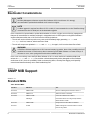
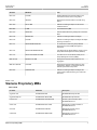
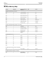
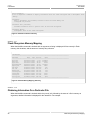
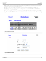
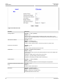
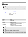
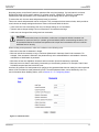
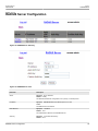
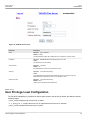
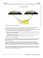
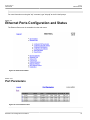
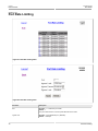
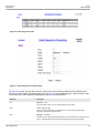
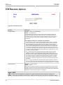
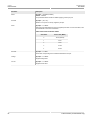
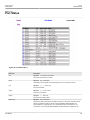
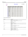
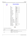
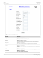
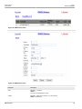
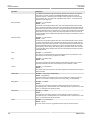
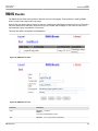
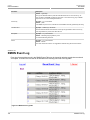
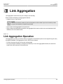
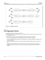
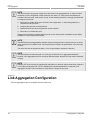
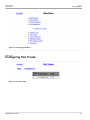
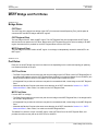
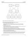
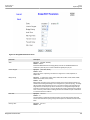
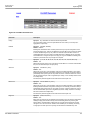
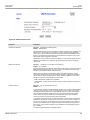
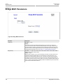
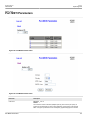
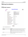
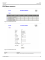
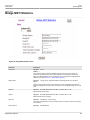
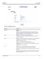
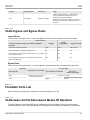
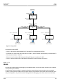
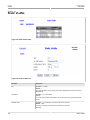
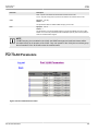
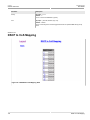
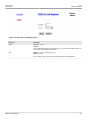
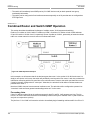
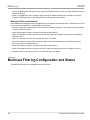
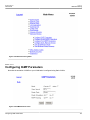
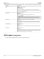
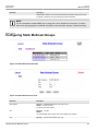
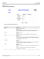
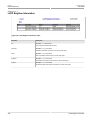
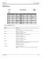
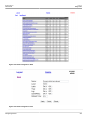
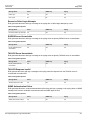
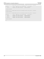
RUGGEDCOM ROS
User Guide
Chapter 5
Link Aggregation
Figure 74: Link Aggregation Menu
Section 5.2.1
Configuring Port Trunks
Figure 75: Port Trunk Table
Configuring Port Trunks
113
Chapter 5
RUGGEDCOM ROS
Link Aggregation
User Guide
Figure 76: Port Trunk Form
Parameter
Description
Trunk ID
Synopsis: 1 to maximum number of port trunks
Default: 1
Trunk number. It doesn't affect port trunk operation in any way and is only used for
identification.
Trunk Name
Synopsis: Any 19 characters
Default:
Provides a description of the aggregated link purpose.
Ports
Synopsis: Any combination of numbers valid for this parameter
Default: None
List of ports aggregated in the trunk.
114
Configuring Port Trunks
RUGGEDCOM ROS
Chapter 6
User Guide
Spanning Tree
Spanning Tree
The RUGGEDCOM family of Ethernet switches provides the latest in IEEE standard Spanning Tree functionality,
including:
• Industry standard support of Rapid Spanning Tree (802.1D-2004), which features a compatibility mode with
legacy STP (802.1D-1998)
• Industry standard support of Multiple Spanning Trees (802.1Q-2005), which is interoperable with both RSTP
and legacy STP.
• RUGGEDCOM RSTP feature enhancements (eRSTP™)
• Superior performance - RSTP will recognize a link failure and put an alternate port into forwarding within
milliseconds
• RSTP may be enabled on a per-port basis
• Ports may be configured as edge ports, which allow rapid transitioning to the forwarding state for non-STP
hosts
• Path costs may be hard-configured or determined by port speed negotiation, in either the STP or RSTP style
• Full bridge and port status displays provide a rich set of tools for performance monitoring and debugging
NOTE
Historically, a device implementing STP on its ports has been referred to as a bridge. Siemens uses
the terms "bridge" and "switch" synonymously.
• SNMP-manageable including newRoot and topologyChange traps
Section 6.1
RSTP Operation
The 802.1D Spanning Tree Protocol (STP) was developed to enable the construction of robust networks that
incorporate redundancy while pruning the active topology of the network to prevent loops. While STP is effective,
it requires that frame transfer halt after a link outage until all bridges in the network are guaranteed to be aware of
the new topology. Using the values recommended by 802.1D, this period lasts 30 seconds.
The Rapid Spanning Tree Protocol (RSTP, IEEE 802.1w) was a further evolution of the 802.1D Spanning Tree
Protocol. It replaced the settling period with an active handshake between bridges that guarantees the rapid
propagation of topology information throughout the network. RSTP also offers a number of other significant
innovations, including:
• Topology changes in RSTP can originate from and be acted upon by any designated bridges, leading to more
rapid propagation of address information, unlike topology changes in STP, which must be passed to the root
bridge before they can be propagated to the network.
• RSTP explicitly recognizes two blocking roles - Alternate and Backup Port - which are included in computations
of when to learn and forward. STP, however, recognizes only one state - Blocking - for ports that should not
forward.
• RSTP bridges generate their own configuration messages, even if they fail to receive any from the root bridge.
This leads to quicker failure detection. STP, by contrast, must relay configuration messages received on the
RSTP Operation
115
Chapter 6
Spanning Tree
RUGGEDCOM ROS
User Guide
root port out its designated ports. If an STP bridge fails to receive a message from its neighbor, it cannot be
sure where along the path to the root a failure occurred.
• RSTP offers edge port recognition, allowing ports at the edge of the network to forward frames immediately
after activation, while at the same time protecting them against loops.
While providing much better performance than STP, IEEE 802.1w RSTP still required up to several seconds to
restore network connectivity when a topology change occurred.
A revised and highly optimized RSTP version was defined in the IEEE standard 802.1D-2004 edition. IEEE
802.1D-2004 RSTP reduces network recovery times to just milliseconds and optimizes RSTP operation for
various scenarios.
ROS supports IEEE 802.1D-2004 RSTP.
Section 6.1.1
RSTP States and Roles
RSTP bridges have roles to play, either root or designated. One bridge - the Root Bridge - is the logical center of
the network. All other bridges in the network are Designated bridges.
RSTP also assigns each port of the bridge a state and a role. The RSTP state describes what is happening at the
port in relation to address learning and frame forwarding. The RSTP role basically describes whether the port is
facing the center or the edges of the network and whether it can currently be used.
State
There are three RSTP states: Discarding, Learning and Forwarding.
The discarding state is entered when the port is first put into service. The port does not learn addresses in this
state and does not participate in frame transfer. The port looks for RSTP traffic in order to determine its role in
the network. When it is determined that the port will play an active part in the network, the state will change to
learning.
Figure 77: Bridge and Port States
116
RSTP States and Roles
RUGGEDCOM ROS
Chapter 6
User Guide
Spanning Tree
The learning state is entered when the port is preparing to play an active part in the network. The port learns
addresses in this state but does not participate in frame transfer. In a network of RSTP bridges, the time spent in
this state is usually quite short. RSTP bridges operating in STP compatibility mode will spend six to 40 seconds in
this state.
After "learning," the bridge will place the port in the forwarding state. The port both learns addresses and
participates in frame transfer while in this state.
NOTE
ROS introduces two more states - Disabled and Link Down. Introduced purely for purposes of
management, these states may be considered subclasses of the RSTP Discarding state. The Disabled
state refers to links for which RSTP has been disabled. The Link Down state refers to links for which
RSTP is enabled but are currently down.
Role
There are four RSTP port roles: Root, Designated, Alternate and Backup.
If the bridge is not the root bridge, it must have a single Root Port. The Root Port is the "best" (i.e. quickest) way
to send traffic to the root bridge.
A port is designated if it is the best port to serve the LAN segment it is connected to. All bridges on the same LAN
segment listen to each others’ messages and agree on which bridge is the designated bridge. The ports of other
bridges on the segment must become either root, alternate or backup ports.
Figure 78: Bridge and Port Roles
A port is alternate when it receives a better message from another bridge on the LAN segment it is connected to.
The message that an Alternate Port receives is better than the port itself would generate, but not good enough to
convince it to become the Root Port. The port becomes the alternate to the current Root Port and will become the
new Root Port should the current Root Port fail. The Alternate Port does not participate in the network.
RSTP States and Roles
117
Chapter 6
RUGGEDCOM ROS
Spanning Tree
User Guide
A port is a Backup Port when it receives a better message from the LAN segment it is connected to, originating
from another port on the same bridge. The port is a backup for another port on the bridge and will become active
if that port fails. The Backup Port does not participate in the network.
Section 6.1.2
Edge Ports
A port may be designated an Edge Port if it is directly connected to an end station. As such, it cannot create
bridging loops in the network and can thus directly transition to forwarding, skipping the listening and learning
stages.
Edge ports that receive configuration messages immediately lose their Edge Port status and become normal
spanning tree ports. A loop created on an improperly connected edge port is thus quickly repaired.
Because an Edge Port services only end stations, topology change messages are not generated when its link
toggles.
Section 6.1.3
Point-to-Point and Multipoint Links
RSTP uses a peer-peer protocol called Proposing-Agreeing to ensure transitioning in the event of a link failure.
This protocol is point-to-point and breaks down in multipoint situations, i.e. when more than two bridges operate
on a shared media link.
If RSTP detects this circumstance (based upon the port’s half duplex state after link up) it will switch off
Proposing-Agreeing. The port must transition through the learning and forwarding states, spending one forward
delay in each state.
There are circumstances in which RSTP will make an incorrect decision about the point-to-point state of the link
simply by examining the half-duplex status, namely:
• The port attaches only to a single partner, but through a half-duplex link.
• The port attaches to a shared media hub through a full-duplex link. The shared media link attaches to more
than one RSTP enabled bridge.
In such cases, the user may configure the bridge to override the half-duplex determination mechanism and force
the link to be treated in the proper fashion.
Section 6.1.4
Path and Port Costs
1
The STP path cost is the main metric by which root and designated ports are chosen . The path cost for a
designated bridge is the sum of the individual port costs of the links between the root bridge and that designated
bridge. The port with the lowest path cost is the best route to the root bridge and is chosen as the root port.
1
In actuality the primary determinant for root port selection is the root bridge ID. Bridge ID is important mainly at network startup when the bridge
with the lowest ID is elected as the root bridge. After startup (when all bridges agree on the root bridge’s ID) the path cost is used to select root
ports. If the path costs of candidates for the root port are the same, the ID of the peer bridge is used to select the port. Finally, if candidate root
ports have the same path cost and peer bridge ID, the port ID of the peer bridge is used to select the root port. In all cases the lower ID, path cost
or port ID is selected as the best.
118
Edge Ports
RUGGEDCOM ROS
Chapter 6
User Guide
Spanning Tree
How Port Costs Are Generated
Port costs can be generated either as a result of link auto-negotiation or manual configuration.
When the link auto-negotiation method is used, the port cost is derived from the speed of the link. This method
is useful when a well-connected network has been established. It can be used when the designer is not too
concerned with the resultant topology as long as connectivity is assured.
Manual configuration is useful when the exact topology of the network must be predictable under all
circumstances. The path cost can be used to establish the topology of the network exactly as the designer
intends.
STP vs. RSTP Costs
The IEEE 802.1D-1998 specification limits port costs to values of 1 to 65536. It recommends that a path cost
corresponding to the 1x10⁹ / link speed be used. Designed at a time when 9600 bps links were state of the art,
this method breaks down in modern use, as the method cannot represent a link speed higher than a gigabit per
second.
In order to remedy this problem in future applications the IEEE 802.1w specification limits port costs to values of
1 to 200000, with a path cost corresponding to the 2x10¹² / link speed.
RUGGEDCOM bridges support interoperability with legacy STP bridges by selecting the style to use. In practice
it makes no difference which style is used as long as it is applied consistently across the network, or if costs are
manually assigned.
Section 6.1.5
Bridge Diameter
The bridge diameter is the maximum number of bridges between any two possible points of attachment of end
stations to the network.
The bridge diameter reflects the realization that topology information requires time to propagate hop by hop
through a network. If configuration messages take too long to propagate end to end through the network, the
result will be an unstable network.
2
There is a relationship between the bridge diameter and the maximum age parameter . To achieve extended
ring sizes, RUGGEDCOM eRSTP™ uses an age increment of ¼ of a second. The value of the maximum bridge
diameter is thus four times the configured maximum age parameter.
NOTE
Raise the value of the maximum age parameter if implementing very large bridged networks or rings.
Section 6.1.6
Fast Root Failover
Siemens’s Fast Root Failover feature is an enhancement to RSTP that may be enabled or disabled via
configuration. Fast Root Failover improves upon RSTP’s handling of root bridge failures in mesh-connected
networks, trading slightly increased failover times for a deterministic recovery time.
Two Fast Root Failover algorithms are available:
2
The RSTP algorithm is as follows: STP configuration messages contain "age" information. Messages transmitted by the root bridge have an age
of 0. As each subsequent designated bridge transmits the configuration message it must increase the age by at least 1 second. When the age
exceeds the value of the maximum age parameter, the next bridge to receive the message immediately discards it.
Bridge Diameter
119
Chapter 6
RUGGEDCOM ROS
Spanning Tree
User Guide
• robust: guarantees a deterministic root failover time, but requires support from all switches in the network,
including the root switch.
• relaxed: ensures a deterministic root failover time in most network configurations, but allows the use of a
standard bridge in the root role.
NOTE
To use RSTP Fast Root Failover, all switches in the network must be RUGGEDCOM switches and
must have the same Fast Root Failover algorithm enabled. In networks mixing RUGGEDCOM and
non-RUGGEDCOM switches, or in those mixing Fast Root Failover algorithms, RSTP Fast Root
Failover will not function properly and root bridge failure will result in an unpredictable failover time.
Fast Root Failover and RUGGEDCOM
• Running RSTP with Fast Root Failover disabled has no impact on RSTP performance.
• Fast Root Failover has no effect on RSTP performance in the case of failures that do not involve the root bridge
or one of its links.
• The extra processing introduced by Fast Root Failover significantly decreases the worst-case failover time
in mesh networks, with a modest increase in the best-case failover time. The effect on failover time in ringconnected networks, however, is only to increase it.
Recommendations On The Use Of Fast Root Failover
• It is not recommended to enable Fast Root Failover in single ring network topologies.
• It is strongly recommended to always connect the root bridge to each of its neighbor bridges using more than
one link.
Section 6.2
MSTP Operation
The Multiple Spanning Tree (MST) algorithm and protocol provide greater control and flexibility than RSTP and
legacy STP. MSTP (Multiple Spanning Tree Protocol) is an extension of RSTP, whereby multiple spanning trees
may be maintained on the same bridged network. Data traffic is allocated to one or another of several spanning
trees by mapping one or more VLANs onto the network.
NOTE
The sophistication and utility of the Multiple Spanning Tree implementation on a given bridged network
is proportional to the amount of planning and design invested in configuring MSTP.
If MSTP is activated on some or all of the bridges in a network with no additional configuration, the result will be a
fully and simply connected network, but at best, the result will be the same as a network using only RSTP. Taking
full advantage of the features offered by MSTP requires a potentially large number of configuration variables
to be derived from an analysis of data traffic on the bridged network, and from requirements for load sharing,
redundancy, and path optimization. Once these parameters have all been derived, it is also critical that they are
consistently applied and managed across all bridges in an MST region.
NOTE
By design, MSTP processing time is proportional to the number of active STP instances. This means
that MSTP will likely be significantly slower than RSTP. Therefore, for mission critical applications,
RSTP should be considered a better network redundancy solution than MSTP.
120
MSTP Operation
RUGGEDCOM ROS
Chapter 6
User Guide
Spanning Tree
Section 6.2.1
MST Regions and Interoperability
In addition to supporting multiple spanning trees in a network of MSTP-capable bridges, MSTP is capable of
interoperating with bridges that support only RSTP or legacy STP, without requiring any special configuration.
An MST region may be defined as the set of interconnected bridges whose MST Region Identification is identical
(see Section 6.4.4, “MST Region Identifier”). The interface between MSTP bridges and non-MSTP bridges, or
between MSTP bridges with different MST Region Identification information, becomes part of an MST Region
boundary.
Bridges outside an MST region will see the entire region as though it were a single (R)STP bridge; the internal
detail of the MST region is hidden from the rest of the bridged network. In support of this, MSTP maintains
separate ‘hop counters’ for spanning tree information exchanged at the MST region boundary versus that
propagated inside the region. For information received at the MST region boundary, the (R)STP Message Age is
incremented only once. Inside the region, a separate Remaining Hop Count is maintained, one for each spanning
tree instance. The external Message Age parameter is referred to the (R)STP Maximum Age Time, whereas the
internal Remaining Hop Counts are compared to an MST region-wide Maximum Hops parameter.
MSTI
An MSTI (Multiple Spanning Tree Instance) is one of sixteen independent spanning tree instances that may be
defined in an MST region (not including the IST – see below). An MSTI is created by mapping a set of VLANs (in
ROS, via the VLAN configuration) to a given MSTI ID. The same mapping must be configured on all bridges that
are intended to be part of the MSTI. Moreover, all VLAN to MSTI mappings must be identical for all bridges in an
MST region.
NOTE
ROS supports 16 MSTIs in addition to the IST
Each MSTI has a topology that is independent of every other. Data traffic originating from the same source and
bound to the same destination but on different VLANs on different MSTIs may therefore travel a different path
across the network.
IST
An MST region always defines an IST (Internal Spanning Tree). The IST spans the entire MST region, and
carries all data traffic that is not specifically allocated (by VLAN) to a specific MSTI. The IST is always computed
and is defined to be MSTI zero.
The IST is also the extension inside the MST region of the CIST (see below), which spans the entire bridged
network, inside and outside of the MST region and all other RSTP and STP bridges, as well as any other MST
regions.
CST
The CST (Common Spanning Tree) spans the entire bridged network, including MST regions and any connected
STP or RSTP bridges. An MST region is seen by the CST as an individual bridge, with a single cost associated
with its traversal.
CIST
The CIST (Common and Internal Spanning Tree) is the union of the CST and the ISTs in all MST regions. The
CIST therefore spans the entire bridged network, reaching into each MST region via the latter’s IST to reach
every bridge on the network.
MST Regions and Interoperability
121
Chapter 6
Spanning Tree
RUGGEDCOM ROS
User Guide
Section 6.2.2
MSTP Bridge and Port Roles
Section 6.2.2.1
Bridge Roles:
CIST Root
The CIST Root is the elected root bridge of the CIST (Common and Internal Spanning Tree), which spans all
connected STP and RSTP bridges and MSTP regions.
CIST Regional Root
The root bridge of the IST within an MST region. The CIST Regional Root is the bridge within an MST region
with the lowest cost path to the CIST Root. Note that the CIST Regional Root will be at the boundary of an MST
region. Note also that it is possible for the CIST Regional Root to be the CIST Root.
MSTI Regional Root
The root bridge for an MSTI within an MST region. A root bridge is independently elected for each MSTI in an
MST region.
Section 6.2.2.2
Port Roles:
Each port on an MST bridge may have more than one role depending on the number and topology of spanning
tree instances defined on the port.
CIST Port Roles
• The Root Port provides the minimum cost path from the bridge to the CIST Root via the CIST Regional Root. If
the bridge itself happens to be the CIST Regional Root, the Root Port is also the Master Port for all MSTIs (see
below), and provides the minimum cost path to a CIST Root located outside the region.
• A Designated Port provides the minimum cost path from an attached LAN, via the bridge to the CIST Regional
Root.
• Alternate and Backup Ports have the same sense that they do in RSTP, described in Section 6.1.1, “RSTP
States and Roles”, under "Roles", but relative to the CIST Regional Root.
MSTI Port Roles
For each MSTI on a bridge:
• The Root Port provides the minimum cost path from the bridge to the MSTI Regional Root, if the bridge itself is
not the MSTI Regional Root.
• A Designated Port provides the minimum cost path from an attached LAN, via the bridge to the MSTI Regional
Root.
• Alternate and Backup Ports have the same sense that they do in RSTP, described in Section 6.1.1, “RSTP
States and Roles”, under "Roles", but relative to the MSTI Regional Root.
The Master Port, which is unique in an MST region, is the CIST Root Port of the CIST Regional Root, and
provides the minimum cost path to the CIST Root for all MSTIs.
122
MSTP Bridge and Port Roles
RUGGEDCOM ROS
User Guide
Chapter 6
Spanning Tree
Boundary Ports
A Boundary Port is a port on a bridge in an MST region that connects to either of: 1) a bridge belonging to a
different MST region, or 2) a bridge supporting only RSTP or legacy STP. A Boundary Port blocks or forwards all
VLANs from all MSTIs and the CIST alike. A Boundary Port may be:
• The CIST Root Port of the CIST Regional Root (and therefore also the MSTI Master Port).
• A CIST Designated Port, CIST Alternate / Backup Port, or Disabled. At the MST region boundary, the MSTI
Port Role is the same as the CIST Port Role.
A Boundary Port connected to an STP bridge will send only STP BPDUs. One connected to an RSTP bridge
need not refrain from sending MSTP BPDUs. This is made possible by the fact that the MSTP carries the CIST
Regional Root Identifier in the field that RSTP parses as the Designated Bridge Identifier.
Section 6.2.3
Benefits of MSTP
Despite the fact that MSTP is configured by default to arrive automatically at a spanning tree solution for each
configured MSTI, advantages may be gained from influencing the topology of MSTIs in an MST region. The fact
that the Bridge Priority and each port cost are configurable per MSTI (see sections Section 6.4.5, “Bridge MSTI
Parameters” and Section 6.4.6, “Port MSTI Parameters”) makes it possible to control the topology of each MSTI
within a region.
Load Balancing
MST can be used to balance data traffic load among (sets of) VLANs, enabling more complete utilization of a
multiply interconnected bridged network.
A bridged network controlled by a single spanning tree will block redundant links by design, in order to avoid
harmful loops. Using MSTP, however, any given link may have a different blocking state for each spanning tree
instance (MSTI), as maintained by MSTP. Any given link, therefore, might be in blocking state for some VLANS
and in forwarding state for other VLANs, depending on the mapping of VLANs to MSTIs.
It is possible to control the spanning tree solution for each MSTI, especially the set of active links for each tree,
by manipulating, per MSTI, the bridge priority and the port costs of links in the network. If traffic is allocated
judiciously to multiple VLANs, redundant interconnections in a bridged network which, using a single spanning
tree, would have gone unused, can now be made to carry traffic.
Isolation of Spanning Tree Reconfiguration
A link failure in an MST region that does not affect the roles of Boundary ports will not cause the CST to be
reconfigured, nor will the change affect other MST regions. This is due to the fact that MSTP information does not
propagate past a region boundary.
MSTP versus PVST
An advantage of MSTP over the Cisco Systems Inc. proprietary PVST protocol is the ability to map multiple
VLANs onto a single MSTI. Since each spanning tree requires processing and memory, the expense of keeping
track of an increasing number of VLANs increases much more rapidly for PVST than for MSTP.
Compatibility with STP and RSTP
No special configuration is required for the bridges of an MST region to connect fully and simply to non-MST
bridges on the same bridged network. Careful planning and configuration is, however, recommended in order to
arrive at an optimal network.
Benefits of MSTP
123
Chapter 6
RUGGEDCOM ROS
Spanning Tree
User Guide
Section 6.2.4
Implementing MSTP on a Bridged Network
It is recommended that the configuration of MSTP on a network proceed in the sequence outlined below.
Naturally, it is also recommended that network analysis and planning inform the steps of configuring the VLAN
and MSTP parameters in particular.
Begin with a set of MSTP-capable Ethernet bridges, and MSTP disabled. For each bridge in the network:
1. Configure and enable RSTP (see sections Section 6.4.1, “Bridge RSTP Parameters” and Section 6.4.2,
“Port RSTP Parameters”). Note that the Max Hops parameter in the Bridge RSTP Parameters menu is the
maximum hop count for MSTP
2. Create the VLANs that will be mapped to MSTIs (see the sections on VLAN Configuration)
3. Map VLANs to MSTIs (via the VLAN Configuration menus). Note that MSTP need not be enabled in order to
map a VLAN to an MSTI. Note also that this mapping must be identical for each bridge that is to belong to the
MST region
4. Configure a Region Identifier and Revision Level. Note that these two items must be identical for each bridge
in the MST region (see Section 6.4.4, “MST Region Identifier”)
5. Verify that the Digest field in the MST Region Identifier menu is identical for each bridge in the MST region. If
it is not, then the set of mappings from VLANs to MSTIs differs
6. Configure Bridge Priority per MSTI (see Section 6.4.5, “Bridge MSTI Parameters”)
7. Configure Port Cost and Priority per port and per MSTI (see Section 6.4.6, “Port MSTI Parameters”)
8. Enable MSTP (see Section 6.4.1, “Bridge RSTP Parameters”)
NOTE
Static VLANs must be used in an MSTP configuration. GVRP is not supported in this case.
Section 6.3
RSTP Applications
Section 6.3.1
RSTP in Structured Wiring Configurations
RSTP allows you to construct structured wiring systems in which connectivity is maintained in the event of link
failures. For example, a single link failure of any of links A through N in Figure 79, would leave all the ports of
bridges 555 through 888 connected to the network.
124
Implementing MSTP on a Bridged Network
RUGGEDCOM ROS
User Guide
Chapter 6
Spanning Tree
Figure 79: Example of a Structured Wiring Configuration
Procedure: Design Considerations for RSTP in Structured Wiring Configurations
1.
Select the design parameters for the network.
What are the requirements for robustness and network fail-over/recovery times? Are there special
requirements for diverse routing to a central host computer? Are there any special port redundancy
requirements?
2.
Identify required legacy support.
Are STP bridges used in the network? These bridges do not support rapid transitioning to forwarding. If these
bridges are present, can they be re-deployed closer to the network edge?
3.
Identify edge ports and ports with half-duplex/shared media restrictions.
Ports that connect to host computers, IEDs and controllers may be set to edge ports in order to guarantee
rapid transitioning to forwarding as well as to reduce the number of topology change notifications in the
network. Ports with half-duplex/shared media restrictions require special attention in order to guarantee that
they do not cause extended fail-over/recovery times.
4.
Choose the root bridge and backup root bridge carefully.
The root bridge should be selected to be at the concentration point of network traffic. Locate the backup root
bridge adjacent to the root bridge. One strategy that may be used is to tune the bridge priority to establish
the root bridge and then tune each bridge’s priority to correspond to its distance from the root bridge.
RSTP in Structured Wiring Configurations
125
Chapter 6
Spanning Tree
5.
RUGGEDCOM ROS
User Guide
Identify desired steady state topology.
Identify the desired steady state topology taking into account link speeds, offered traffic and QOS. Examine
of the effects of breaking selected links, taking into account network loading and the quality of alternate links.
6.
Decide upon port cost calculation strategy.
Select whether fixed or auto-negotiated costs should be used? Select whether the STP or RSTP cost style
should be used.
7.
Calculate and configure priorities and costs.
8.
Implement the network and test under load.
Section 6.3.2
RSTP in Ring Backbone Configurations
RSTP may be used in ring backbone configurations where rapid recovery from link failure is required. In normal
operation, RSTP will block traffic on one of the links, for example as indicated by the double bars through link H in
Figure 80. In the event of a failure on link D, bridge 444 will unblock link H. Bridge 333 will communicate with the
network through link F.
Figure 80: Example of a Ring Backbone Configuration
Procedure: Design Considerations for RSTP in Ring Backbone Configurations
1.
Select the design parameters for the network.
What are the requirements for robustness and network fail-over/recovery times? Typically, ring backbones
are chosen to provide cost effective but robust network designs.
126
RSTP in Ring Backbone Configurations
RUGGEDCOM ROS
User Guide
2.
Chapter 6
Spanning Tree
Identify required legacy support and ports with half-duplex/shared media restrictions.
These bridges should not be used if network fail-over/recovery times are to be minimized.
3.
Identify edge ports
Ports that connect to host computers, IEDs and controllers may be set to edge ports in order to guarantee
rapid transitioning to forwarding as well as to reduce the number of topology change notifications in the
network.
4.
Choose the root bridge.
The root bridge can be selected to equalize either the number of bridges, number of stations or amount of
traffic on either of its legs. It is important to realize that the ring will always be broken in one spot and that
traffic always flows through the root.
5.
Assign bridge priorities to the ring.
The strategy that should be used is to assign each bridge’s priority to correspond to its distance from the root
bridge. If the root bridge is assigned the lowest priority of 0, the bridges on either side should use a priority
of 4096 and the next bridges 8192 and so on. As there are 16 levels of bridge priority available, this method
provides for up to 31 bridges in the ring.
6.
Implement the network and test under load.
Section 6.3.3
RSTP Port Redundancy
Figure 81: Port Redundancy
In cases where port redundancy is essential, RSTP allows more than one bridge port to service a LAN. For
example, if port 3 is designated to carry the network traffic of LAN A, port 4 will block. Should an interface failure
occur on port 3, port 4 would assume control of the LAN.
Section 6.4
Spanning Tree Configuration
The Spanning Tree menu is accessible from the main menu.
RSTP Port Redundancy
127
Chapter 6
Spanning Tree
RUGGEDCOM ROS
User Guide
Figure 82: Spanning Tree Menu
Section 6.4.1
Bridge RSTP Parameters
The Bridge RSTP Parameter form configures RSTP bridge-level parameters.
128
Bridge RSTP Parameters
RUGGEDCOM ROS
Chapter 6
User Guide
Spanning Tree
Figure 83: Bridge RSTP Parameter Form
Parameter
Description
State
Synopsis: { Disabled, Enabled }
Default: Enabled
Enable STP/RSTP/MSTP for the bridge globally. Note that for STP/RSTP/MSTP to be
enabled on a particular port, it must be enabled both globally and per port.
Version Support
Synopsis: { STP, RSTP, MSTP }
Default: RSTP
Selects the version of Spanning Tree Protocol to support one of: STP, Rapid STP, or
Multiple STP.
Bridge Priority
Synopsis: { 0, 4096, 8192, 12288, 16384, 20480, 24576, 28672, 32768, 36864, 40960,
45056, 49152, 53248, 57344, 61440 }
Default: 32768
Bridge Priority provides a way to control the topology of the STP connected network. The
desired Root and Designated bridges can be configured for a particular topology. The bridge
with the lowest priority will become the root. In the event of a failure of the root bridge, the
bridge with the next lowest priority will then become the root. Designated bridges that (for
redundancy purposes) service a common LAN also use priority to determine which bridge is
active. In this way, careful selection of Bridge Priorities can establish the path of traffic flows
in normal and abnormal conditions.
Hello Time
Synopsis: 1 s to 10 s
Default: 2 s
The time between configuration messages issued by the root bridge. Shorter hello times
result in faster detection of topology changes at the expense of moderate increases in STP
traffic.
Max Age Time
Bridge RSTP Parameters
Synopsis: 6 s to 40 s
Default: 20 s
129
Chapter 6
RUGGEDCOM ROS
Spanning Tree
Parameter
User Guide
Description
The time for which a configuration message remains valid after being issued by the root
bridge. Configure this parameter with care when many tiers of bridges exist, or when slow
speed links (such as those used in WANs) are part of the network.
Transmit Count
Synopsis: 3 to 100 or { Unlimited }
Default: Unlimited
The maximum number of BPDUs on each port that may be sent in one second. Larger
values allow the network to recover from failed links/bridges more quickly.
Forward Delay
Synopsis: 4 s to 30 s
Default: 15 s
The amount of time a bridge spends learning MAC addresses on a rising port before
beginning to forward traffic. Lower values allow the port to reach the forwarding state more
quickly, but at the expense of flooding unlearned addresses to all ports.
Max Hops
Synopsis: 6 to 40
Default: 20
This parameter is only relevant for MSTP - ignore it otherwise.This parameter specifies
the maximum possible bridge diameter inside an MST region. MSTP BPDUs propagating
inside an MST region carry a time-to-live parameter that is decremented by every switch
that propagates the BPDU. If the maximum number of hops inside the region exceeds the
configured maximum, BPDUs may be discarded due to their time-to-live information.
Section 6.4.2
Port RSTP Parameters
Figure 84: Port RSTP Parameter Table
130
Port RSTP Parameters
RUGGEDCOM ROS
Chapter 6
User Guide
Spanning Tree
Figure 85: Port RSTP Parameter Form
Parameter
Description
Port(s)
Synopsis: Any combination of numbers valid for this parameter
The port number as seen on the front plate silkscreen of the switch (or a list of ports, if
aggregated in a port trunk).
Enabled
Synopsis: { Disabled, Enabled }
Default: Enabled
Enabling STP activates the STP or RSTP protocol for this port per the configuration in the
STP Configuration menu. STP may be disabled for the port ONLY if the port does not attach
to an STP enabled bridge in any way. Failure to meet this requirement WILL result in an
undetectable traffic loop in the network. A better alternative to disabling the port is to leave
STP enabled but to configure the port as an edge port. A good candidate for disabling STP
would be a port that services only a single host computer.
Priority
Synopsis: { 0, 16, 32, 48, 64, 80, 96, 112, 128, 144, 160, 176, 194, 208, 224, 240 }
Default: 128
Selects the STP port priority. Ports of the same cost that attach to a common LAN will select
the port to be used based upon the port priority.
STP Cost
Synopsis: 0 to 65535 or { Auto }
Default: Auto
Selects the cost to use in cost calculations, when the Cost Style parameter is set to STP in
the Bridge RSTP Parameters configuration. Setting the cost manually provides the ability to
preferentially select specific ports to carry traffic over others. Leave this field set to "auto" to
use the standard STP port costs as negotiated (4 for 1Gbps, 19 for 100 Mbps links and 100
for 10 Mbps links).
For MSTP, this parameter applies to both external and internal path cost.
RSTP Cost
Synopsis: 0 to 2147483647 or { Auto }
Default: Auto
Selects the cost to use in cost calculations, when the Cost Style parameter is set to RSTP in
the Bridge RSTP Parameters configuration. Setting the cost manually provides the ability to
preferentially select specific ports to carry traffic over others. Leave this field set to "auto" to
use the standard RSTP port costs as negotiated (20,000 for 1Gbps, 200,000 for 100 Mbps
links and 2,000,000 for 10 Mbps links).
For MSTP, this parameter applies to both external and internal path cost.
Edge Port
Synopsis: { False, True, Auto }
Default: Auto
Edge ports are ports that do not participate in the Spanning Tree, but still send configuration
messages. Edge ports transition directly to frame forwarding without any listening and
learning delays. The MAC tables of Edge ports do not need to be flushed when topology
changes occur in the STP network. Unlike an STP disabled port, accidentally connecting
an edge port to another port in the spanning tree will result in a detectable loop. The
Port RSTP Parameters
131
Chapter 6
RUGGEDCOM ROS
Spanning Tree
Parameter
User Guide
Description
"Edgeness" of the port will be switched off and the standard RSTP rules will apply (until the
next link outage).
Point to Point
Synopsis: { False, True, Auto }
Default: Auto
RSTP uses a peer-to-peer protocol that provides rapid transitioning on point-to-point
links. This protocol is automatically turned off in situations where multiple STP bridges
communicate over a shared (non point-to-point) LAN. The bridge will automatically take
point-to-point to be true when the link is found to be operating in full-duplex mode. The
point-to-point parameter allows this behavior or overrides it, forcing point-to-point to be true
or false. Force the parameter true when the port operates a point-to-point link but cannot
run the link in full-duplex mode. Force the parameter false when the port operates the link in
full-duplex mode, but is still not point-to-point (e.g. a full-duplex link to an unmanaged bridge
that concentrates two other STP bridges).
Restricted Role
Synopsis: { True or False }
Default: False
A boolean value set by management. If TRUE, causes the Port not to be selected as the
Root Port for the CIST or any MSTI, even if it has the best spanning tree priority vector.
Such a Port will be selected as an Alternate Port after the Root Port has been selected.
This parameter should be FALSE by default. If set, it can cause a lack of spanning tree
connectivity. It is set by a network administrator to prevent bridges that are external to a
core region of the network from influencing the spanning tree active topology. This may be
necessary, for example, if those bridges are not under the full control of the administrator.
Restricted TCN
Synopsis: { True or False }
Default: False
A boolean value set by management. If TRUE, it causes the Port not to propagate received
topology change notifications and topology changes to other Ports. If set, it can cause
temporary loss of connectivity after changes in a spanning tree’s active topology as a
result of persistent, incorrectly learned, station location information. It is set by a network
administrator to prevent bridges that are external to a core region of the network from
causing address flushing in that region. This may be necessary, for example, if those
bridges are not under the full control of the administrator or if the MAC_Operational status
parameter for the attached LANs transitions frequently.
Section 6.4.3
eRSTP Parameters
The eRSTP Parameter form configures parameters relevant to different eRSTP enhancements.
132
eRSTP Parameters
RUGGEDCOM ROS
Chapter 6
User Guide
Spanning Tree
Figure 86: eRSTP Parameter Form
Parameter
Description
Max Network Diameter
Synopsis: { MaxAgeTime, 4*MaxAgeTime }
Default: 4*MaxAgeTime
The RSTP standard puts a limit on the maximum network size that can be controlled by the
RSTP protocol. The network size is described by the term ‘maximum network diameter’,
which is the number of switches that comprise the longest path that RSTP BPDUs have to
traverse. The standard supported maximum network diameter is equal to the value of the
‘MaxAgeTime’ RSTP configuration parameter.
eRSTP offers an enhancement to RSTP which allows it to cover networks larger than ones
defined by the standard. This configuration parameter selects the maximum supported
network size.
BPDU Guard Timeout
Synopsis: 1 to 86400 s or { Until reset, Don’t shutdown }
Default: Don’t shutdown
The RSTP standard does not address network security. RSTP must process every received
BPDU and take appropriate action. This opens a way for an attacker to influence RSTP
topology by injecting RSTP BPDUs into the network.
"BPDU Guard" is a feature that protects the network from BPDUs received by a port to
which RSTP capable devices are not expected to be attached. If a BPDU is received by a
port for which the ‘Edge’ parameter is set to ‘TRUE’ or RSTP is disabled, the port will be
shut down for the time period specified by this parameter.
• DON’T SHUTDOWN - BPDU Guard is disabled.
• UNTIL RESET - port will remain shut down until the port reset command is issued by the
operator.
Fast Root Failover
Synopsis: { On, On with standard root, Off }
Default: On
In mesh network topologies, the standard RSTP algorithm does not guarantee deterministic
network recovery time in the case of a root bridge failure. Such a recovery time is hard to
calculate and it can be different (and may be relatively long) for any given mesh topology.
This configuration parameter enables Siemens’s enhancement to RSTP which detects
a failure of the root bridge and takes some extra RSTP processing steps, significantly
reducing the network recovery time and making it deterministic.
To guarantee optimal performance, the Fast Root Failover algorithm must be supported by
all switches in the network, including the root. However, it is not uncommon to assign the
root role to a switch from a vendor different from the rest of the switches in the network. In
this case, it is possible that the root might not support the Fast Root Failover algorithm. In
this scenario, use the "relaxed" algorithm, which tolerates the lack of algorithm support in
the root switch.
The following are the supported configuration options:
eRSTP Parameters
133
Chapter 6
RUGGEDCOM ROS
Spanning Tree
Parameter
User Guide
Description
• On – Fast Root Failover is enabled and the most robust algorithm is used, which requires
the appropriate support in the root switch.
• On with standard root – Fast Root Failover is enabled but a "relaxed" algorithm is used,
allowing the use of a standard switch in the root role.
• Off – Fast Root Failover algorithm is disabled and hence a root switch failure may result in
excessive connectivity recovery time.
NOTE
This feature is only available in RSTP mode. In MSTP mode, the configuration
parameter is ignored. In a single ring topology, this feature is not needed and
should be disabled to avoid longer network recovery times due to extra RSTP
processing. For recommendations regarding the use of this feature, refer to
Section 6.1.6, “Fast Root Failover”.
IEEE802.1w Interoperability
Synopsis: { On, Off }
Default: On
The original RSTP protocol defined in the IEEE 802.1w standard has minor differences from
more recent, enhanced, standard(s). Those differences cause interoperability issues which,
although they do not completely break RSTP operation, can lead to a longer recovery time
from failures in the network.
eRSTP offers some enhancements to the protocol which make the switch fully interoperable
with other vendors’ switches, which may be running IEEE 802.2w RSTP. The enhancements
do not affect interoperability with more recent RSTP editions. This configuration parameter
enables the aforementioned interoperability mode.
Cost Style
Synopsis: { STP (16 bit), RSTP (32 bit) }
Default: STP (16 bit)
The RSTP standard defines two styles of a path cost value. STP uses 16-bit path costs
based on 1x10E9/link speed (4 for 1Gbps, 19 for 100 Mbps and 100 for 10 Mbps) whereas
RSTP uses 32-bit costs based upon 2x10E13/link speed (20,000 for 1Gbps, 200,000 for
100 Mbps and 2,000,000 for 10 Mbps). Switches from some vendors, however, use the
STP path cost style even in RSTP mode, which can cause confusion and problems with
interoperability.
This configuration parameter selects the style of path cost to employ. Note that RSTP path
costs are used only when the bridge version support is set to allow RSTP and the port does
not migrate to STP.
134
eRSTP Parameters
RUGGEDCOM ROS
Chapter 6
User Guide
Spanning Tree
Section 6.4.4
MST Region Identifier
Figure 87: MST Region Identifier Form
Parameter
Description
Name
Synopsis: Any 32 characters
Default: 00-0A-DC-00-41-74
Variable length text string. You must configure an identical region name on all switches you
want to be in the same MST region.
Revision Level
Synopsis: 0 to 65535
Default: 0
Use this parameter, if you want to create a new region from a subset of switches in a current
region, while maintaining the same region name.
Digest
Synopsis: 32 hex characters
This is a read-only parameter and should be only used for network troubleshooting. In order
to ensure consistent VLAN-to-instance mapping, it is necessary for the protocol to be able
to exactly identify the boundaries of the MST regions. For that purpose, the characteristics
of the region are included in BPDUs. There is no need to propagate the exact VLAN-toinstance mapping in the BPDUs because switches only need to know whether they are in
the same region as a neighbor. Therefore, only this 16-octet digest created from the VLANto-instance mapping is sent in BPDUs.
MST Region Identifier
135
Chapter 6
RUGGEDCOM ROS
Spanning Tree
User Guide
Section 6.4.5
Bridge MSTI Parameters
Figure 88: Bridge MSTI Parameters
Parameter
Description
Instance ID
Synopsis: 0 to 16
Default: 1
The Instance ID refers to the MSTI (Multiple Spanning Tree Instance) ID. Specify an
Instance ID and select GET in order to load the parameters of the page corresponding to
the selected MSTI. Changes to parameters that are subsequently applied will apply to the
selected Instance ID. Note: Bridge Parameters for the IST (MSTI zero) are accessible via
the Bridge RSTP Parameters menu (see Section 6.4.1, “Bridge RSTP Parameters”).
Bridge Priority
Synopsis: { 0, 4096, 8192, 12288, 16384, 20480, 24576, 28672, 32768, 36864, 40960,
45056, 49152, 53248, 57344, 61440 }
Default: 32768
Bridge Priority provides a way to control the topology of the STP connected network. The
desired Root and Designated bridges can be configured for a particular topology. The
bridge with the lowest priority will become root. In the event of a failure of the root bridge,
the bridge with the next lowest priority will then become root. Designated bridges that (for
redundancy purposes) service a common LAN also use priority to determine which bridge is
active. In this way careful selection of Bridge Priorities can establish the path of traffic flows
in both normal and abnormal conditions.
136
Bridge MSTI Parameters
RUGGEDCOM ROS
Chapter 6
User Guide
Spanning Tree
Section 6.4.6
Port MSTI Parameters
Figure 89: Port MSTI Parameter Table
Figure 90: Port MSTI Parameter Form
Parameter
Description
Instance ID
Synopsis: 0 to 16
Default: 1
The Instance ID refers to the MSTI (Multiple Spanning Tree Instance) ID. Specify an
Instance ID and select GET in order to load parameters corresponding to the selected
MSTI. Changes to parameters that are subsequently applied will apply to the selected
Port MSTI Parameters
137
Chapter 6
RUGGEDCOM ROS
Spanning Tree
Parameter
User Guide
Description
Instance ID. Note: Port Parameters for the IST (MSTI zero), are accessible via the Port
RSTP Parameters menu (see Section 6.4.2, “Port RSTP Parameters”).
Port(s)
Synopsis: Any combination of numbers valid for this parameter
The port number as seen on the front plate silkscreen of the switch (or a list of ports, if
aggregated in a port trunk).
Priority
Synopsis: { 0, 16, 32, 48, 64, 80, 96, 112, 128, 144, 160, 176, 194, 208, 224, 240 }
Default: 128
Selects the STP port priority. Ports of the same cost that attach to a common LAN will select
the port to be used based on the port priority.
STP Cost
Synopsis: 0 to 65535 or { Auto }
Default: Auto
Selects the cost to use in cost calculations when the Cost Style parameter is set to STP in
the Bridge RSTP Parameters configuration. Setting the cost manually provides the ability to
preferentially select specific ports to carry traffic over others. Leave this field set to "auto" to
use the standard STP port costs as negotiated (4 for 1Gbps, 19 for 100 Mbps links and 100
for 10 Mbps links). For MSTP, this parameter applies to both external and internal path cost.
RSTP Cost
Synopsis: 0 to 2147483647 or { Auto }
Default: Auto
Selects the cost to use in cost calculations when the Cost Style parameter is set to RSTP in
the Bridge RSTP Parameters configuration. Setting the cost manually provides the ability to
preferentially select specific ports to carry traffic over others. Leave this field set to "auto" to
use the standard RSTP port costs as negotiated (20,000 for 1Gbps, 200,000 for 100 Mbps
links and 2,000,000 for 10 Mbps links). For MSTP, this parameter applies to both external
and internal path cost.
138
Port MSTI Parameters
RUGGEDCOM ROS
Chapter 6
User Guide
Spanning Tree
Section 6.5
Spanning Tree Statistics
Section 6.5.1
Bridge RSTP Statistics
Figure 91: Bridge RSTP Statistics Form
Parameter
Description
Bridge Status
Synopsis: { <empty string>, Designated Bridge, Not Designated For Any LAN, Root
Bridge }
Spanning Tree status of the bridge. The status may be root or designated. This field may
display "Not designated For Any LAN" if the bridge is not the designated bridge for any of its
ports.
Bridge ID
Synopsis: $$ / ##-##-##-##-##-## where $$ is 0 to 65535, ## is 0 to FF
Bridge Identifier of this bridge.
Spanning Tree Statistics
139
Chapter 6
RUGGEDCOM ROS
Spanning Tree
User Guide
Parameter
Description
Root ID
Synopsis: $$ / ##-##-##-##-##-## where $$ is 0 to 65535, ## is 0 to FF
Bridge Identifier of the root bridge.
Regional Root ID
Synopsis: $$ / ##-##-##-##-##-## where $$ is 0 to 65535, ## is 0 to FF
Bridge Identifier of the IST regional root bridge for the MST region this device belongs to.
Root Port
Synopsis: 0 to 65535 or { <empty string>}
If the bridge is designated, this is the port that provides connectivity towards the root bridge
of the network.
Root Path Cost
Synopsis: 0 to 4294967295
The total cost of the path to the root bridge, composed of the sum of the costs of each link
in the path. If custom costs have not been configured. 1Gbps ports will contribute a cost of
four, 100 Mbps ports will contribute 19 and 10 Mbps ports will contribute 100. For the CIST
instance of MSTP, this is an external root path cost, which is the cost of the path from the
IST root (i.e. regional root) bridge to the CST root (i.e. network "global" root) bridge.
Configured Hello Time
Synopsis: 0 to 65535
The configured Hello time from the Bridge RSTP Parameters menu.
Learned Hello Time
Synopsis: 0 to 65535
The actual Hello time provided by the root bridge as learned in configuration messages.
This time is used in designated bridges.
Configured Forward Delay
Synopsis: 0 to 65535
The configured Forward Delay time from the Bridge RSTP Parameters menu.
Learned Forward Delay
Synopsis: 0 to 65535
The actual Forward Delay time provided by the root bridge as learned in configuration
messages. This time is used in designated bridges.
Configured Max Age
Synopsis: 0 to 65535
The configured Maximum Age time from the Bridge RSTP Parameters menu.
Learned Max Age
Synopsis: 0 to 65535
The actual Maximum Age time provided by the root bridge as learned in configuration
messages. This time is used in designated bridges.
Total Topology Changes
Synopsis: 0 to 65535
A count of topology changes in the network, as detected on this bridge through link failures
or as signaled from other bridges. Excessively high or rapidly increasing counts signal
network problems.
Time since Last TC
Synopsis: D days, HH:MM:SS
Displays the time since the last topology change.
140
Bridge RSTP Statistics
RUGGEDCOM ROS
Chapter 6
User Guide
Spanning Tree
Section 6.5.2
Port RSTP Statistics
Figure 92: Port RSTP Statistics Table
Figure 93: Port RSTP Statistics Form
Parameter
Description
Port(s)
Synopsis: Any combination of numbers valid for this parameter
Port RSTP Statistics
141
Chapter 6
RUGGEDCOM ROS
Spanning Tree
Parameter
User Guide
Description
The port number as seen on the front plate silkscreen of the switch (or a list of ports, if
aggregated in a port trunk).
Status
Synopsis: { Disabled, Listening, Learning, Forwarding, Blocking, Link Down, Discarding }
The status of this port in the Spanning Tree. This may be one of the following:
Disabled - STP is disabled on this port.
Link Down - STP is enabled on this port but the link is down.
Discarding - The link is not used in the STP topology but is standing by.
Learning - The port is learning MAC addresses in order to prevent flooding when it begins
forwarding traffic.
Forwarding - The port is forwarding traffic.
Role
Synopsis: { <empty string>, Root, Designated, Alternate, Backup, Master }
The role of this port in the Spanning Tree. This may be one of the following:
Designated - The port is designated for (i.e. carries traffic towards the root for) the LAN it is
connected to.
Root - The single port on the bridge, which provides connectivity towards the root bridge.
Backup - The port is attached to a LAN that is serviced by another port on the bridge. It is
not used but is standing by.
Alternate - The port is attached to a bridge that provides connectivity to the root bridge. It is
not used but is standing by.
Cost
Synopsis: 0 to 4294967295
Cost offered by this port. If the Bridge RSTP Parameters Cost Style is set to STP, 1Gbps
ports will contribute a cost of four, 100 Mbps ports will contribute 19 and 10 Mbps ports
contribute 100. If the Cost Style is set to RSTP, 1Gbps will contribute 20,000, 100 Mbps
ports will contribute a cost of 200,000 and 10 Mbps ports contribute a cost of 2,000,000.
Note that even if the Cost Style is set to RSTP, a port that migrates to STP will have its cost
limited to a maximum of 65535.
RX RSTs
Synopsis: 0 to 4294967295
The count of RSTP configuration messages received on this port.
TX RSTs
Synopsis: 0 to 4294967295
The count of RSTP configuration messages transmitted on this port.
RX Configs
Synopsis: 0 to 4294967295
The count of STP configuration messages received on this port.
TX Configs
Synopsis: 0 to 4294967295
The count of STP configuration messages transmitted on this port.
RX Tcns
Synopsis: 0 to 4294967295
The count of configuration change notification messages received on this port. Excessively
high or rapidly increasing counts signal network problems.
TX Tcns
Synopsis: 0 to 4294967295
The count of configuration messages transmitted from this port.
Desig Bridge ID
Synopsis: $$ / ##-##-##-##-##-## where $$ is 0 to 65535, ## is 0 to FF
Provided on the root ports of designated bridges, the Bridge Identifier of the bridge this port
is connected to.
operEdge
Synopsis: { True or False }
Whether or not the port is operating as an edge port.
142
Port RSTP Statistics
RUGGEDCOM ROS
Chapter 6
User Guide
Spanning Tree
Section 6.5.3
Bridge MSTI Statistics
Figure 94: Bridge MSTI Statistics Form
Parameter
Description
Instance ID
Synopsis: 0 to 16
Default: 1
The Instance ID refers to the MSTI (Multiple Spanning Tree Instance) ID. Specify an
Instance ID and select GET in order to load parameters corresponding to the selected
MSTI. Note: Bridge Statistics for the IST (MSTI zero), are accessible via the Bridge RSTP
Statistics menu (see Section 6.5.1, “Bridge RSTP Statistics”).
Bridge Status
Synopsis: { <empty string>, Designated Bridge, Not Designated For Any LAN, Root
Bridge }
Spanning Tree status of the bridge. The status may be root or designated. This field may
display "Not designated For Any LAN" if the bridge is not the designated bridge for any of its
ports.
Bridge ID
Synopsis: $$ / ##-##-##-##-##-## where $$ is 0 to 65535, ## is 0 to FF
Bridge Identifier of this bridge.
Root ID
Synopsis: $$ / ##-##-##-##-##-## where $$ is 0 to 65535, ## is 0 to FF
Bridge Identifier of the root bridge.
Root Port
Synopsis: 0 to 65535 or { <empty string>}
If the bridge is designated, this is the port that provides connectivity towards the root bridge
of the network.
Root Path Cost
Bridge MSTI Statistics
Synopsis: 0 to 4294967295
143
Chapter 6
RUGGEDCOM ROS
Spanning Tree
Parameter
User Guide
Description
The total cost of the path to the root bridge composed of the sum of the costs of each link
in the path. If custom costs have not been configured. 1Gbps ports will contribute a cost of
four, 100 Mbps ports will contribute 19 and 10 Mbps ports will contribute 100 to this figure.
For the CIST instance of MSTP, this is an external root path cost, which is the cost of the
path from the IST root (i.e. regional root) bridge to the CST root (i.e. network "global" root)
bridge.
Total Topology Changes
Synopsis: 0 to 65535
A count of topology changes in the network, as detected on this bridge through link failures
or as signaled from other bridges. Excessively high or rapidly increasing counts signal
network problems.
Time since Last TC
Synopsis: D days, HH:MM:SS
Displays the time since the last topology change on the specific MSTI instance.
Section 6.5.4
Port MSTI Statistics
Figure 95: Port MSTI Statistics Table
144
Port MSTI Statistics
RUGGEDCOM ROS
Chapter 6
User Guide
Spanning Tree
Figure 96: Port MSTI Statistics Form
Parameter
Description
Instance ID
Synopsis: 1 to 16
Default: 1
The Instance ID refers to the MSTI (Multiple Spanning Tree Instance) ID. Specify an
Instance ID and select GET in order to load parameters corresponding to the selected
MSTI. Note: Port Statistics for the IST (MSTI zero), are accessible via the Port RSTP
Statistics menu (see Section 6.5.2, “Port RSTP Statistics”).
Port(s)
Synopsis: Any combination of numbers valid for this parameter
The port number as seen on the front plate silkscreen of the switch (or a list of ports, if
aggregated in a port trunk).
Status
Synopsis: { Disabled, Listening, Learning, Forwarding, Blocking, Link Down, Discarding }
The status of this port in the Spanning Tree. This may be one of the following:
Disabled - STP is disabled on this port.
Link Down - STP is enabled on this port but the link is down.
Discarding - The link is not used in the STP topology but is standing by.
Learning - The port is learning MAC addresses in order to prevent flooding when it begins
forwarding traffic.
Forwarding - The port is forwarding traffic.
Role
Synopsis: { <empty string>, Root, Designated, Alternate, Backup, Master }
The role of this port in the Spanning Tree. This may be one of the following:
Designated - The port is designated for (i.e. carries traffic towards the root for) the LAN it is
connected to.
Root - The single port on the bridge, which provides connectivity towards the root bridge.
Backup - The port is attached to a LAN that is serviced by another port on the bridge. It is
not used but is standing by.
Port MSTI Statistics
145
Chapter 6
RUGGEDCOM ROS
Spanning Tree
Parameter
User Guide
Description
Alternate - The port is attached to a bridge that provides connectivity to the root bridge. It is
not used but is standing by.
Master - Only exists in MSTP. The port is an MST region boundary port and the single port
on the bridge, which provides connectivity for the Multiple Spanning Tree Instance towards
the Common Spanning Tree root bridge (i.e. this port is the root port for the Common
Spanning Tree Instance).
Cost
Synopsis: 0 to 4294967295
Cost offered by this port. If the Bridge RSTP Parameters Cost Style is set to STP, 1Gbps
ports will contribute a cost of four, 100 Mbps ports will contribute 19 and 10 Mbps ports
contribute. If the Cost Style is set to RSTP, 1Gbps will contribute 20,000, 100 Mbps ports
will contribute a cost of 200,000 and 10 Mbps ports contribute a cost of 2,000,000. Note that
even if the Cost Style is set to RSTP, a port that migrates to STP will have its cost limited to
a maximum of 65535.
Desig Bridge ID
Synopsis: $$ / ##-##-##-##-##-## where $$ is 0 to 65535, ## is 0 to FF
Provided on the root ports of designated bridges, the Bridge Identifier of the bridge this port
is connected to.
Section 6.5.5
Clear STP Statistics
Clicking the Clear Spanning Tree Statistics link on the main Spanning Tree menu (see Figure 82) presents the
following confirmation form:
Figure 97: Clear Spanning Tree Statistics Confirmation Form
Click the Confirm button to clear all statistics maintained by ROS for spanning tree, including global and portbased statistics.
Section 6.6
Troubleshooting
Problem One
When I connect a new port the network locks up. The port status LEDs are flashing madly.
Occasionally, the network seems to experience a lot of flooding. All the ports seem to experience significant
traffic. The problem lasts a few seconds and then goes away.
146
Clear STP Statistics
RUGGEDCOM ROS
User Guide
Chapter 6
Spanning Tree
One of my switches displays a strange behavior where the root port hops back and forth between two switch
ports and never settles down.
Is it possible that one of the switches in the network or one of the ports on a switch in the network has STP
disabled and accidentally connects to another switch? If this has occurred, then a traffic loop has been formed.
If the problem appears to be transient in nature, it is possible that ports that are part of the spanning tree have
been configured as edge ports. After the link layers have come up on edge ports, STP will directly transition them
(perhaps improperly) to the forwarding state. If an RSTP configuration message is then received, the port will be
returned to blocking. A traffic loop may be formed for the length of time the port was in forwarding.
If one of the switches appears to flip the root from one port to another, the problem may be one of traffic
prioritization (See problem five).
Another possible cause of intermittent operation is that of an auto-negotiation mismatch. If one end of the link
is fixed to full-duplex mode and the peer auto-negotiates, the auto-negotiating end will fall back to half-duplex
operation. At lower traffic, the volumes the link may display few if any errors. As the traffic volume rises, the
fixed negotiation side will begin to experience dropped packets while the auto-negotiating side will experience
collisions. Ultimately, as traffic loads approach 100%, the link will become entirely unusable. At this point, RSTP
will not be able to transmit configuration messages over the link and the spanning tree topology will break
down. If an alternate trunk exists, RSTP will activate it in the place of the congested port. Since activation of the
alternate port often relieves the congested port of its traffic, the congested port will once again become reliable.
RSTP will promptly enter it back into service, beginning the cycle once again. The root port will flip back and forth
between two ports on the switch.
Problem Two
My PC/IED/Device is connected to your switch. After I reset the switch, it takes a long time before it comes up.
Is it possible that the RSTP edge setting for this port is set to false? If Edge is set to false, the bridge will make
the port go through two forward delay times before the port can send or receive frames. If Edge is set to true, the
bridge will transition the port directly to forwarding upon link up.
Another possible explanation is that some links in the network run in half-duplex mode. RSTP uses a peerto-peer protocol called Proposal-Agreement to ensure transitioning in the event of a link failure. This protocol
requires full-duplex operation. When RSTP detects a non-full duplex port, it cannot rely on Proposal-Agreement
protocol and must make the port transition the slow (i.e. STP) way. If possible, configure the port for full-duplex
operation. Otherwise, configure the port’s point-to-point setting to true. Either one will allow the ProposalAgreement protocol to be used.
Problem Three
When I test your switch by deliberately breaking a link, it takes a long time before I can poll devices past the
switch. I thought RSTP was supposed to be fast. What is happening?
Is it possible that some ports participating in the topology have been configured to STP mode or that the port’s
point-to-point parameter is set to false? STP and multipoint ports converge slowly after failures occur.
Is it possible that the port has migrated to STP? If the port is connected to the LAN segment by shared media and
STP bridges are connected to that media, then convergence after link failure will be slow.
Delays on the order of tens or hundreds of milliseconds can result in circumstances where the link broken is
the sole link to the root bridge and the secondary root bridge is poorly chosen. The worst of all possible designs
occurs when the secondary root bridge is located at the farthest edge of the network from the root. In this case, a
configuration message will have to propagate out to the edge and then back in order to reestablish the topology.
Problem Four
My network is composed of a ring of bridges, of which two (connected to each other) are managed and the rest
are unmanaged. Why does the RSTP protocol work quickly when I break a link between the managed bridges but
not in the unmanaged bridge part of the ring?
Troubleshooting
147
Chapter 6
Spanning Tree
RUGGEDCOM ROS
User Guide
A properly operating unmanaged bridge is transparent to STP configuration messages. The managed bridges will
exchange configuration messages through the unmanaged bridge part of the ring as if it is non-existent. When
a link in the unmanaged part of the ring fails however, the managed bridges will only be able to detect the failure
through timing out of hello messages. Full connectivity will require three hello times plus two forwarding times to
be restored.
Problem Five
The switch is up and running and working fine. Then I start a certain application and the network becomes
unstable. After I stop the application, the network goes back to running normally.
RSTP sends its configuration messages using the highest possible priority level. If CoS is configured to allow
traffic flows at the highest priority level and these traffic flows burst continuously to 100% of the line bandwidth,
STP may be disrupted. It is therefore advised not to use the highest CoS.
Problem Six
After I bring up a new port, the root moves on to that port, and I don’t want it to. The port that I want to become
root won’t do so.
Is it possible that the port cost is incorrectly programmed or that auto-negotiation derives an undesired value?
Inspect the port and path costs with each port active as root.
Problem Seven
My IED/Controller does not work with your switch.
Certain low CPU bandwidth controllers have been found to behave less than perfectly when they receive
unexpected traffic. Try disabling STP for the port.
If the controller fails around the time of a link outage then there is the remote possibility that frame disordering or
duplication may be the cause of the problem. Try setting the root port of the failing controller’s bridge to STP.
Problem Eight
My network runs fine with your switch but I occasionally lose polls to my devices.
Inspect network statistics to determine whether the root bridge is receiving TCNs around the time of observed
frame loss. It may be possible that you have problems with intermittent links in your network.
Problem Nine
I’m getting a lot of TCNs at the root, where are they coming from?
Examine the RSTP port statistics to determine the port from which the TCNs are arriving. Sign-on to the switch at
the other end of the link attached to that port. Repeat this step until the switch generating the TCNs is found (i.e.
the switch that is itself not receiving a large number of TCNs). Determine the problem at that switch.
148
Troubleshooting
RUGGEDCOM ROS
Chapter 7
User Guide
VLANs
VLANs
ROS provides the following VLAN features:
• Support for up to 255 VLANs
• Configurable port-native VLAN.
• Port modes of operation tailored to edge devices (such as a PC or IED) and to network switch
interconnections.
• A default setting that ensures configuration-free connectivity in certain scenarios.
• Ability to force either tagged or untagged operation on the port-native VLAN.
• Ability to switch between VLAN-aware and VLAN-unaware modes of operation.
• GARP VLAN Registration Protocol (GVRP).
• Double VLAN-tagging, or QinQ
• Configurable management VLAN
Section 7.1
VLAN Operation
Section 7.1.1
VLANs and Tags
A virtual LAN or VLAN is a group of devices on one or more LAN segments that communicate as if they were
attached to the same physical LAN segment. VLANs are extremely flexible because they are based on logical
instead of physical connections.
When VLANs are introduced, all traffic in the network must belong to one or another VLAN. Traffic on one VLAN
cannot pass to another, except through an internetwork router or Layer 3 switch.
A VLAN tag is the identification information that is present in frames in order to support VLAN operation.
Section 7.1.2
Tagged vs. Untagged Frames
Tagged frames are frames with 802.1Q (VLAN) tags that specify a valid VLAN identifier (VID). Untagged frames
are frames without tags or frames that carry 802.1p (prioritization) tags only having prioritization information and a
VID of 0. Frames with a VID=0 are also called priority-tagged frames.
When a switch receives a tagged frame, it extracts the VID and forwards the frame to other ports in the same
VLAN.
VLAN Operation
149
Chapter 7
RUGGEDCOM ROS
VLANs
User Guide
Section 7.1.3
Native VLAN
Each port is assigned a native VLAN number, the Port VLAN ID (PVID). When an untagged frame ingresses a
port, it is associated with the port’s native VLAN.
By default, when the switch transmits a frame on the native VLAN, it sends the frame untagged. The switch can
be configured to transmit frames on the native VLAN tagged.
Section 7.1.4
Management VLAN
Management traffic, like all traffic on the network, must belong to a specific VLAN. The management VLAN
is configurable and always defaults to VLAN 1. This VLAN is also the default native VLAN for all ports, thus
allowing all ports the possibility of managing the product. Changing the management VLAN can be used to
restrict management access to a specific set of users.
Section 7.1.5
Edge and Trunk Port Types
Each port can be configured to take on a type of Edge or Trunk.
Edge Type
An Edge port attaches to a single end device (such as a PC or IED) and carries traffic on a single pre-configured
VLAN, the native VLAN.
Trunk Type
Trunk ports are part of the network and carry traffic for all VLANs between switches.
Trunk ports are automatically members of all VLANs configured in the switch.
The switch can "pass through" traffic, forwarding frames received on one trunk port out another trunk port. The
trunk ports must be members of all the VLANs the "pass through" traffic is part of, even if none of those VLANs
are used on edge ports.
Frames transmitted out of the port on all VLANs other than the port’s native VLAN are always sent tagged.
NOTE
Sometimes it may be desirable to manually restrict the traffic on the trunk to a certain group of VLANs.
For example, when the trunk connects to a device (such as a Layer 3 router) that supports a subset of
the available VLANs. The trunk port can be prevented from being a member of the VLAN by including it
in the VLAN’s Forbidden Ports list.
Port Type
Edge
150
VLANs Supported
PVID Format
Usage
Untagged
VLAN Unaware networks – All frames are sent and
received without the need for VLAN tags.
Tagged
VLAN Aware networks – VLAN traffic domains are
enforced on a single VLAN.
1 (Native) Configured
Native VLAN
RUGGEDCOM ROS
Chapter 7
User Guide
VLANs
Port Type
VLANs Supported
Trunk
All Configured
PVID Format
Usage
Tagged or Untagged
Switch-to-Switch connections – VLANs must be
manually created and administered or can be
dynamically learned through GVRP.
Multiple-VLAN end devices – Implement connections
to end devices that support multiple VLANs at the
same time.
Section 7.1.6
VLAN Ingress and Egress Rules
Ingress Rules
These are the VLAN ingress rules, i.e. the rules applied to all frames when they are received by the switch:
Frame received
Priority
Tagged (VID=0)
Untagged
This does not depend on ingress port's VLAN configuration
parameters
Tagged >(valid VID)
VLAN ID associated with the frame
PVID
PVID
VID in the tag
Frame dropped due to its tagged/untagged format
No
No
No
Frame dropped, if VLAN associated with the frame is not configured
(or learned) in the switch
N/A
N/A
Yes
Frame dropped, if ingress port is not a member of the VLAN the
frame is associated with
N/A
N/A
No
Egress Rules
These are the VLAN egress rules, i.e. the rules applied to all frames when they are transmitted by the switch:
Frame sent
Egress port type
Edge
Trunk
On other VLAN
On egress port’s native VLAN
According to the egress port’s
"PVID Format" parameter
Port is a member of the VLAN
Port is not a
member of the VLAN
N/A (frame is dropped)
Tagged
dropped
Section 7.1.7
Forbidden Ports List
Each VLAN can be configured to exclude ports from membership in the VLAN.
Section 7.1.8
VLAN-aware And VLAN-unaware Modes Of Operation
The native operation mode for an IEEE 802.1Q compliant switch is VLAN-aware. Even if a specific network
architecture does not use VLANs, ROS default VLAN settings allow the switch still to operate in a VLAN-aware
VLAN Ingress and Egress Rules
151
Chapter 7
RUGGEDCOM ROS
VLANs
User Guide
mode while providing functionality required for almost any network application. However, the IEEE 802.1Q
standard defines a set of rules that must be followed by all VLAN-aware switches, for example:
• Valid VID range is 1 to 4094 (VID=0 and VID=4095 are invalid).
• Each frame ingressing a VLAN-aware switch is associated with a valid VID.
• Each frame egressing a VLAN-aware switch is either untagged or tagged with a valid VID (this means prioritytagged frames with VID=0 are never sent out by a VLAN-aware switch).
It turns out that some applications have requirements conflicting with the IEEE 802.1Q native mode of operation
(e.g. some applications explicitly require priority-tagged frames to be received by end devices).
To ensure the required operation in any possible application scenario and provide full compatibility with legacy
(VLAN-unaware) devices, the device can be configured to work in a VLAN-unaware mode.
In that mode:
• Frames ingressing a VLAN-unaware switch are not associated with any VLAN.
• Frames egressing a VLAN-unaware switch are sent out unmodified, i.e. in the same untagged, 802.1Q-tagged
or priority-tagged format as they were received.
Section 7.1.9
GVRP (GARP VLAN Registration Protocol)
GVRP is a standard protocol built on GARP (the Generic Attribute Registration Protocol) to automatically
distribute VLAN configuration information in a network. Each switch in a network needs only to be configured with
VLANs it requires locally; it dynamically learns the rest of the VLANs configured elsewhere in the network via
GVRP. A GVRP-aware end station, configured for a particular VLAN ID, can be connected to a trunk on a GVRPaware switch and automatically become part of the desired VLAN.
When a switch sends GVRP BPDUs out of all GVRP-enabled ports, GVRP BPDUs advertise all the VLANs
known to that switch (configured anually or learned dynamically through GVRP) to the rest of the network.
When a GVRP-enabled switch receives a GVRP BPDU advertising a set of VLANs, the receiving port becomes
a member of those advertised VLANs and the switch begins advertising those VLANs via all the GVRP-enabled
ports (other than the port on which the VLANs were learned).
To improve network security using VLANs, GVRP-enabled ports may be configured to prohibit the learning of any
new dynamic VLANs but at the same time be allowed to advertise the VLANs configured on the switch.
152
GVRP (GARP VLAN Registration Protocol)
RUGGEDCOM ROS
Chapter 7
User Guide
VLANs
End Node D
GVRP aware
Port D2– GVRP aware
Adv. & Learn
Edge Switch
D
Port D1 – GVRP aware
Adv. & Learn
Port B3 – GVRP aware
Adv. & Learn
Port B1 – GVRP aware
Adv. & Learn
Core Switch
B
Port B2 – GVRP aware
Adv. & Learn
Port B4 – GVRP aware
Adv. & Learn
Port A1 –GVRP aware
Adv. only
Port E1 – GVRP aware
Adv. Only
Edge Switch
A
Port A2– Edge Port
PVID - 7
End Node A
GVRP unaware
Port C1 – GVRP aware
Adv. only
Edge Switch
E
Port E2– Edge Port
PVID - 20
Edge Switch
C
Port C2– Edge Port
End Node E
GVRP Unaware
PVID - 7
End Node C
GVRP Unaware
Figure 98: Using GVRP
An example of using GVRP:
• Ports A2, and C2 are configured with PVID 7 and port E2 is configured with PVID 20.
• End Node D is GVRP aware and is interested in VLAN 20, hence VLAN 20 is advertised by it towards switch D.
• D2 becomes member of VLAN 20.
• Ports A1 and C1 advertise VID 7 and ports B1 and B2 become members of VLAN 7.
• Ports D1 and B1 advertise VID 20 and ports B3, B4 and D1 become members of VLAN 20.
Section 7.1.10
QinQ
QinQ is also known as double VLAN-tagging or as Nested VLANs. It is used to overlay a private Layer 2 network
over a public Layer 2 network.
A large network service provider, for example, might have several clients whose networks each use multiple
VLANs. It is likely that the VLAN IDs used by these different client networks would conflict with one another, were
they mixed together in the provider's network. Using double VLAN-tagging, each client network could be further
QinQ
153
Chapter 7
RUGGEDCOM ROS
VLANs
User Guide
tagged using a client-specific VID at the edges where the clients' networks are connected to the network service
provider's infrastructure.
Frames ingressing an edge port of the service provider switch are tagged with VIDs of the customer’s private
network. When those frames egress the switch's QinQ-enabled port into the service provider network the switch
always adds an extra tag (called outer tag) on top of the frames’ original VLAN tag (called inner tag) and the outer
tag VID is the PVID of the frames’ ingress edge port. This means that traffic from an individual customer is tagged
with his unique VID and is thus segregated from other customers’ traffic.
Within the service provider network, switching is based on the VID in the outer tag.
When double-tagged frames leave the service provider network, they egress a QinQ-enabled port of another
switch. The switch strips the outer tag while associating the frames with the VID extracted from it before stripping.
Thus, the frames are switched to appropriate edge ports, i.e. to appropriate customers.
Figure 99: Using QinQ Example
NOTE
QinQ can only be enabled on one switch port at a time.
NOTE
Some switch models only support QinQ if all edge ports are configured with the same PVID. In this
case, a dedicated switch must be assigned to each customer.
154
QinQ
RUGGEDCOM ROS
User Guide
Chapter 7
VLANs
Section 7.2
VLAN Applications
Section 7.2.1
Traffic Domain Isolation
VLANs are most often used for their ability to restrict traffic flows between groups of devices.
Unnecessary broadcast traffic can be restricted to the VLAN that requires it. Broadcast storms in one VLAN need
not affect users in other VLANs.
Hosts on one VLAN can be prevented from accidentally or deliberately assuming the IP address of a host on
another VLAN.
By configuring the management VLAN, a management domain can be established that restricts the number of
users able to modify the configuration of the network.
The use of creative bridge filtering and multiple VLANs can carve seemingly unified IP subnets into multiple
regions policed by different security/access policies.
Multi-VLAN hosts can assign different traffic types to different VLANs.
Figure 100: Multiple Overlapping VLANs
VLAN Applications
155
Chapter 7
VLANs
RUGGEDCOM ROS
User Guide
Section 7.2.2
Administrative Convenience
VLANs enable equipment moves to be handled by software reconfiguration instead of by physical cable
management. When a host’s physical location is changed, its connection point is often changed as well. With
VLANs, the host’s VLAN membership and priority are simply copied to the new port.
Section 7.2.3
Reduced Hardware
Without VLANs, traffic domain isolation requires using separate bridges for separate networks. VLANs eliminate
the need for separate bridges.
The number of network hosts may often be reduced. Often, a server is assigned to provide services for
independent networks. These hosts may be replaced by a single, multi-homed host supporting each network on
its own VLAN. This host can perform routing between VLANs.
Figure 101: Inter-VLAN Communications
Section 7.3
VLAN Configuration
The Virtual LANs menu is accessible from the main menu.
156
Administrative Convenience
RUGGEDCOM ROS
Chapter 7
User Guide
VLANs
Figure 102: Virtual LANs Menu
Section 7.3.1
Global VLAN Parameters
Figure 103: Global VLAN Parameters Form
Parameter
Description
VLAN-aware
Synopsis: { No, Yes }
Default: Yes
Set either VLAN-aware or VLAN-unaware mode of operation.
NOTE
Do not attempt to change the "VLAN-aware" parameter of the managed switch by applying a
configuration (.CSV) file update. Configuration file updates are used to apply "bulk changes" to the
current configuration of a switch. Instead, a change to this individual parameter MUST first be applied
separately from any other table (i.e. parameter) changes. In other words, configuration file updates
should exclude the "VLAN-aware" parameter.
Global VLAN Parameters
157
Chapter 7
RUGGEDCOM ROS
VLANs
User Guide
Section 7.3.2
Static VLANs
Figure 104: Static VLANs Table
Figure 105: Static VLANs Form
Parameter
Description
VID
Synopsis: 1 to 4094
Default: 1
The VLAN Identifier is used to identify the VLAN in tagged Ethernet frames according to
IEEE 802.1Q.
VLAN Name
Synopsis: Any 19 characters
Default:
The VLAN name provides a description of the VLAN purpose (for example, Engineering
VLAN).
Forbidden Ports
Synopsis: Any combination of numbers valid for this parameter
Default: None
These are ports that are not allowed to be members of the VLAN.
Examples:
158
Static VLANs
RUGGEDCOM ROS
Chapter 7
User Guide
VLANs
Parameter
Description
None - all ports of the switch are allowed to be members of the VLAN
2,4-6,8 - all ports except ports 2,4,5,6 and 8 are allowed to be members of the VLAN
Synopsis: { Off, On }
Default: Off
IGMP
This parameter enables or disables IGMP Snooping on the VLAN.
Synopsis: 0 to 16
Default: 0
MSTI
This parameter is only valid for Multiple Spanning Tree Protocol (MSTP) and has no effect,
if MSTP is not used. The parameter specifies the Multiple Spanning Tree Instance (MSTI) to
which the VLAN should be mapped.
NOTE
If IGMP Snooping is not enabled for the VLAN, both IGMP messages and multicast streams will be
forwarded directly to all members of the VLAN. If any one member of the VLAN joins a multicast group
then all members of the VLAN will receive the multicast traffic.
Section 7.3.3
Port VLAN Parameters
Figure 106: Port VLAN Parameters Table
Port VLAN Parameters
159
Chapter 7
RUGGEDCOM ROS
VLANs
User Guide
Figure 107: Port VLAN Parameters Form
Parameter
Description
Port(s)
Synopsis: Any combination of numbers valid for this parameter
The port number as seen on the front plate silkscreen of the switch (or a list of ports, if
aggregated in a port trunk).
Type
Synopsis: {Edge, Trunk, QinQ}
Default: Edge
This parameter specifies how the port determines its membership in VLANs. There are few
types of ports:
Edge - the port is only a member of one VLAN (its native VLAN specified by the 'PVID'
parameter).
Trunk - the port is automatically a member of all configured VLANs. Frames transmitted out
of the port on all VLANs except the port's native VLAN will be always tagged. It can also be
configured to use GVRP for automatic VLAN configuration.
QinQ - the port is a trunk port using double-VLAN tagging, or nested VLANs. An extra VLAN
tag is always added to all frames egressing this port. VID in the added extra tag is the PVID
of the frame's ingress port. VLAN tag is always stripped from frames ingressing this port.
PVID
Synopsis: 1 to 4094
Default: 1
The Port VLAN Identifier specifies the VLAN ID associated with untagged (and 802.1p
priority tagged) frames received on this port.
Frames tagged with a non-zero VLAN ID will always be associated with the VLAN ID
retrieved from the frame tag.
Modify this parameter with care! By default, the switch is programmed to use VLAN 1 for
management and every port on the switch is programmed to use VLAN 1. If you modify a
switch port to use a VLAN other than the management VLAN, devices on that port will not
be able to manage the switch.
PVID Format
Synopsis: { Untagged, Tagged }
Default: Untagged
Specifies whether frames transmitted out of the port on its native VLAN (specified by the
'PVID' parameter) will be tagged or untagged.
GVRP
160
Synopsis: { Adv&Learn, Adv Only, Disabled }
Default: Disabled
Port VLAN Parameters
RUGGEDCOM ROS
Chapter 7
User Guide
VLANs
Parameter
Description
Configures GVRP (Generic VLAN Registration Protocol) operation on the port. There are
several GVRP operation modes:
DISABLED - the port is not capable of any GVRP processing.
ADVERTISE ONLY - the port will declare all VLANs existing in the switch (configured or
learned) but will not learn any VLANs.
ADVERTISE & LEARN - the port will declare all VLANs existing in the switch (configured or
learned) and can dynamically learn VLANs.
Only Trunk ports are GVRP-capable.
Section 7.3.4
VLAN Summary
There are actually three ways that a VLAN can be created in the switch:
Explicit
A VLAN is explicitly configured in the Static VLANs list.
Implicit
A VLAN ID is a parameter required for different feature configurations (e.g. Port VLAN Parameters, Static MAC
Addresses, IP Interface Type and ID). When such a parameter is set to some VLAN ID value, appropriate VLAN
is automatically created, if it does not yet exist.
Dynamic
A VLAN learned through GVRP.
NOTE
Not explicitly created VLAN is always created with IGMP Snooping disabled. If it is desirable for IGMP
to be used on that VLAN, it should be created as a Static VLAN with IGMP enabled.
All VLANs, regardless of the way they were created, are shown in the VLAN Summary.
Figure 108: VLAN Summary Table
Parameter
Description
VID
Synopsis: 1 to 4094
VLAN Summary
161
Chapter 7
RUGGEDCOM ROS
VLANs
User Guide
Parameter
Description
The VLAN Identifier is used to identify the VLAN in tagged Ethernet frames according to
IEEE 802.1Q.
Untagged Ports
Synopsis: Any combination of numbers valid for this parameter
All ports that are untagged members of the VLAN.
Tagged Ports
Synopsis: Any combination of numbers valid for this parameter
All ports that are tagged members of the VLAN.
Section 7.4
Troubleshooting
Problem One
I don’t need VLANs at all. How do I turn them off?
Simply leave all ports set to type "Edge" and leave the native VLAN set to 1. This is the default configuration for
the switch.
Problem Two
I have added two VLANs: 2 and 3. I made a number of ports members of these VLANS. Now I need some of the
devices in one VLAN to send messages to some devices in the other VLAN.
If the devices need to communicate at the physical address layer, they must be members of the same VLAN. If
they can communicate in a Layer 3 fashion (i.e. using a protocol such as IP or IPX), you can use a router. The
router will treat each VLAN as a separate interface, which will have its own associated IP address space.
Problem Three
I have a network of thirty switches for which I wish to restrict management traffic to a separate domain. What is
the best way of doing this while still staying in contact with these switches?
At the switch where the management station is located, configure a port to use the new management VLAN as its
native VLAN. Configure a host computer to act as a temporary management station.
At each switch, configure the management VLAN to the new value. As each switch is configured, you will
immediately lose contact with it, but should be able to re-establish communications from the temporary
management station. After all switches have been taken to the new management VLAN, configure the ports of all
attached management devices to use the new VLAN.
NOTE
Establishing a management domain is often accompanied with the establishment of an IP subnet
specifically for the managed devices.
162
Troubleshooting
RUGGEDCOM ROS
Chapter 8
User Guide
Port Security
Port Security
ROS™ Port Security provides you with the following features:
• Authorizing network access using Static MAC Address Table.
• Authorizing network access using IEEE 802.1X authentication.
• Configuring IEEE 802.1X authentication parameters.
• Detecting port security violation attempt and performing appropriate actions.
Section 8.1
Port Security Operation
Port Security, or Port Access Control, provides the ability to filter or accept traffic from specific MAC addresses.
Port Security works by inspecting the source MAC addresses of received frames and validating them against the
list of MAC addresses authorized on the port. Unauthorized frames will be filtered and, optionally, the port that
receives the frame will be shut down permanently or for a period of time. An alarm will be raised indicating the
detected unauthorized MAC address.
Frames to unknown destination addresses will not be flooded through secure ports.
NOTE
Port security is applied at the edge of the network in order to restrict admission to specific devices. Do
not apply port security on core switch connections.
ROS supports several MAC address authorization methods.
Section 8.1.1
Static MAC Address-Based Authorization
• With this method, the switch validates the source MAC addresses of received frames against the contents in
the Static MAC Address Table.
• ROS also supports a highly flexible Port Security configuration which provides a convenient means for network
administrators to use the feature in various network scenarios.
• A Static MAC address can be configured without a port number being explicitly specified. In this case, the
configured MAC address will be automatically authorized on the port where it is detected. This allows devices
to be connected to any secure port on the switch without requiring any reconfiguration.
• The switch can also be programmed to learn (and, thus, authorize) a preconfigured number of the first source
MAC addresses encountered on a secure port. This enables the capture of the appropriate secure addresses
when first configuring MAC address-based authorization on a port. Those MAC addresses are automatically
inserted into the Static MAC Address Table and remain there until explicitly removed by the user.
Port Security Operation
163
Chapter 8
Port Security
RUGGEDCOM ROS
User Guide
Section 8.1.2
IEEE 802.1X Authentication
The IEEE 802.1X standard defines a mechanism for port-based network access control and provides a means of
authenticating and authorizing devices attached to LAN ports.
Although 802.1X is mostly used in wireless networks, this method is also implemented in wired switches.
The 802.1X standard defines three major components of the authentication method: Supplicant, Authenticator
and Authentication server.
Figure 109: 802.1X General Topology
RUGGEDCOM supports the Authenticator component.
802.1X makes use of Extensible Authentication Protocol (EAP) which is a generic PPP authentication protocol
and supports various authentication methods. 802.1X defines a protocol for communication between the
Supplicant and the Authenticator, EAP over LAN (EAPOL).
RUGGEDCOM communicates with the Authentication Server using EAP over RADIUS.
Figure 110: 802.1X Packet Exchange
164
IEEE 802.1X Authentication
RUGGEDCOM ROS
Chapter 8
User Guide
Port Security
NOTE
The switch supports authentication of one host per port.
NOTE
If the host’s MAC address is configured in the Static MAC Address Table, it will be authorized, even if
the host authentication is rejected by the authentication server.
Section 8.1.3
IEEE 802.1X with MAC-Authentication
This method is also known as MAB (MAC-Authentication Bypass). It is commonly used for devices, such as VoIP
phones and Ethernet printers, that do not support the 802.1X protocol. This method allows such devices to be
authenticated using the same database infrastructure as that used in 802.1X.
IEEE 802.1X with MAC-Authentication Bypass works as follows:
1. The device connects to a switch port.
2. The switch learns the device MAC address upon receiving the first frame from the device (the device usually
sends out a DHCP request message when first connected).
3. The switch sends an EAP Request message to the device, attempting to start 802.1X authentication.
4. The switch times out while waiting for the EAP reply, because the device does not support 802.1X.
5. The switch sends an authentication message to the authentication server, using the device MAC address as
the username and password.
6. The switch authenticates or rejects the device according to the reply from the authentication server.
Section 8.1.4
VLAN Assignment with Tunnel Attributes
ROS supports assigning a VLAN to the authorized port using tunnel attributes, as defined in RFC3580, when the
Port Security mode is set to 802.1X or 802.1X/MAC-Auth.
In some cases, it may be desirable to allow a port to be placed into a particular VLAN, based on the
authentication result. For example:
• to allow a particular device, based on its MAC address, to remain on the same VLAN as it moves within a
network, configure the switches for 802.1X/MAC-Auth mode.
• to allow a particular user, based on the user’s login credentials, to remain on the same VLAN when the user
logs in from different locations, configure the switches for 802.1X mode.
If the RADIUS server wants to use this feature, it indicates the desired VLAN by including tunnel attributes in the
Access-Accept message. The RADIUS server uses the following tunnel attributes for VLAN assignment:
• Tunnel-Type=VLAN (13)
• Tunnel-Medium-Type=802
• Tunnel-Private-Group-ID=VLANID
Note that VLANID is 12-bits and takes a value between 1 and 4094, inclusive. The Tunnel-Private-Group-ID is a
String as defined in RFC2868, so the VLANID integer value is encoded as a string.
IEEE 802.1X with MAC-Authentication
165
Chapter 8
Port Security
RUGGEDCOM ROS
User Guide
If the tunnel attributes are not returned by the authentication server, the VLAN assigned to the switch port
remains unchanged.
Section 8.2
Port Security Configuration
The Ports Security menu is accessible from the main menu.
Figure 111: Ports Security Menu
Section 8.2.1
Ports Security Parameters
Figure 112: Ports Security Parameters Table
166
Port Security Configuration
RUGGEDCOM ROS
Chapter 8
User Guide
Port Security
Figure 113: Ports Security Parameters Form
Parameter
Description
Port
Synopsis: 1 to maximum port number
Default: 1
The port number as seen on the front plate silkscreen of the switch.
Security
Synopsis: { Off, Static MAC, 802.1X, 802.1x/MAC-Auth }
Default: Off
Enables or disables the port's security feature. Two types of port access control are
available:
• Static MAC address-based. With this method, authorized MAC address(es) should be
configured in the Static MAC Address table. If some MAC addresses are not known in
advance (or it is not known to which port they will be connected), there is still an option to
configure the switch to auto-learn certain number of MAC addresses. Once learned, they
do not age out until the unit is reset or the link goes down.
• IEEE 802.1X standard authentication.
• IEEE 802.1X with MAC-Authentication, also known as MAC-Authentication Bypass. With
this option, the device can authenticate clients based on the client’s MAC address if IEEE
802.1X authentication times out.
Autolearn
Synopsis: 1 to 16 or { None }
Default: None
Only applicable when the 'Security' field has been set to 'Static MAC'. It specifies maximum
number of MAC addresses that can be dynamically learned on the port. If there are static
addresses configured on the port, the actual number of addresses allowed to be learned is
this number minus the number of the static MAC addresses.
Sticky
Synopsis: { No, Yes }
Default: Yes
Only applicable when the 'Security' field has been set to 'Static MAC'. Change the behaviour
of the port to either sticky or non-sticky.
If Sticky is 'Yes', MACs/Devices authorized on the port 'stick' to the port and the switch will
not allow them to move to a different port.
If Sticky is 'No', MACs/Devices authorized on the port may move to another port.
Shutdown Time
Synopsis: 1 to 86400 s or { Until reset, Don't shutdown }
Default: Don't shutdown
Specifies for how long to shut down the port, if a security violation occurs.
Status
Ports Security Parameters
Synopsis: Any 31 characters
167
Chapter 8
RUGGEDCOM ROS
Port Security
User Guide
Parameter
Description
Describes the security status of the port.
NOTE
There are a few scenarios in which static MAC addresses can move:
• When the link is up/down on a non-sticky secured port
• When traffic switches from or to a non-sticky secured port
NOTE
Traffic is lost until the source MAC Address of the incoming traffic is authorized against the static MAC
address table.
Section 8.2.2
802.1X Parameters
Figure 114: 802.1X Parameters Table
168
802.1X Parameters
RUGGEDCOM ROS
Chapter 8
User Guide
Port Security
Figure 115: 802.1X Parameters Form
Parameter
Description
Port
Synopsis: 1 to maximum port number
Default: 1
The port number as seen on the front plate silkscreen of the switch.
txPeriod
Synopsis: 1 to 65535
Default: 30 s
The time to wait for the Supplicant's EAP Response/Identity packet before retransmitting an
EAP Request/Identity packet.
quietPeriod
Synopsis: 0 to 65535
Default: 60 s
The period of time not to attempt to acquire a Supplicant after the authorization session
failed.
reAuthEnabled
Synopsis: { No, Yes }
Default: No
Enables or disables periodic re-authentication.
reAuthPeriod
Synopsis: 60 to 86400
Default: 3600 s
The time between periodic re-authentication of the Supplicant.
reAuthMax
Synopsis: 1 to 10
Default: 2
The number of re-authentication attempts that are permitted before the port becomes
unauthorized.
suppTimeout
802.1X Parameters
Synopsis: 1 to 300
Default: 30 s
169
Chapter 8
RUGGEDCOM ROS
Port Security
User Guide
Parameter
Description
The time to wait for the Supplicant's response to the authentication server's EAP packet.
serverTimeout
Synopsis: 1 to 300
Default: 30 s
The time to wait for the authentication server's response to the Supplicant's EAP packet.
Synopsis: 1 to 10
Default: 2
maxReq
The maximum number of times to retransmit the authentication server's EAP Request
packet to the Supplicant before the authentication session times out.
Section 8.2.3
Viewing Authorized MAC Addresses
The Authorized MAC Address Table lists the static MAC addresses learned from secure ports.
NOTE
Only MAC addresses authorized on a static MAC port(s) are shown in the Authorized MAC Address
Table. MAC addresses authorized with 802.1X or 802.1X MAC AUTH are not shown.
Figure 116: Authorized MAC Addresses Table
Parameter
Description
Port
Synopsis: 0 to 4294967295
Port on which MAC address has been learned.
MAC Address
Synopsis: ##-##-##-##-##-## where ## ranges 0 to FF
Authorized MAC address learned by the switch.
VID
Synopsis: 0 to 65535
VLAN Identifier of the VLAN upon which the MAC address operates.
Sticky
Synopsis: { No, Yes }
This describes whether the authorized MAC address/Device can move to another port or
not:
• YES - authorized MAC address/Device cannot move to a different switch port
• NO - authorized MAC address/Device may move to another switch port
170
Viewing Authorized MAC Addresses
RUGGEDCOM ROS
Chapter 9
User Guide
Classes of Service
Classes of Service
ROS CoS provides the following features:
• Support for 4 Classes of Service
• Ability to prioritize traffic by ingress port.
• Ability to prioritize traffic by the priority field in 802.1Q tags.
• Ability to prioritize traffic based on its source or destination MAC address.
• Ability to prioritize traffic by the TOS field in the IP header.
Section 9.1
CoS Operation
CoS provides the ability to expedite the transmission of certain frames and port traffic over others.
The CoS of a frame can take on one of four values: Normal, Medium, High or Critical.
The default policies of the switch enforce a Normal CoS for all traffic.
NOTE
Use the highest supported CoS with caution, as it is always used by the switch for handling network
management traffic such as STP BPDUs.
If this CoS is used for regular network traffic, upon traffic bursts, it may result in loss of some network
management frames which in its turn may result in loss of connectivity over the network.
The CoS feature has two main phases - inspection and forwarding:
Section 9.1.1
Inspection Phase
In the inspection phase, the CoS priority of a received frame is determined from:
• A specific CoS based upon the source and destination MAC address (as set in the Static MAC Address Table)
• The priority field in 802.1Q tags
• The Differentiated Services Code Point (DSCP) component of the Type Of Service (TOS) field in the IP header,
if the frame is IP
• The default CoS for the port
Each frame’s CoS will be determined once the first examined parameter is found in the frame.
NOTE
For information on how to configure the Inspect TOS parameter, refer to Section 9.2.2, “Port CoS
Parameters”.
CoS Operation
171
Chapter 9
Classes of Service
RUGGEDCOM ROS
User Guide
Received frames are first examined to determine if their destination or source MAC address is found in the Static
MAC Address Table. If they are, the CoS configured for the static MAC address is used. If neither destination or
source MAC address is in the Static MAC Address Table or the CoS for the MAC address is set to N/A, the frame
is then examined for 802.1Q tags and the priority field is mapped to a CoS. If a tag is not present, the frame is
examined to determine if it is an IP frame. If the frame is an IP frame and Inspect TOS is enabled in ROS, the
CoS is determined from the DSCP field. If the frame is not an IP frame or Inspect TOS is disabled, the default
CoS for the port is used.
After inspection, the frame is forwarded to the egress port for transmission.
Section 9.1.2
Forwarding Phase
The inspection phase results in the CoS of individual frames being determined. When these frames are
forwarded to the egress port, they are collected into one of the priority queues according to the CoS assigned to
each frame.
CoS weighting selects the degree of preferential treatment that is attached to different priority queues. The ratio
of the number of higher CoS to lower CoS frames transmitted can be programmed. If desired, the user can
program lower CoS frames are to be transmitted only after all higher CoS frames have been serviced.
Section 9.2
CoS Configuration
The Classes Of Service menu is accessible from the main menu.
Figure 117: Classes Of Service Menu
172
Forwarding Phase
RUGGEDCOM ROS
Chapter 9
User Guide
Classes of Service
Section 9.2.1
Global CoS Parameters
Figure 118: Global CoS Parameters Form
Parameter
Description
CoS Weighting
Synopsis: { 8:4:2:1, Strict }
Default: 8:4:2:1
During traffic bursts, frames queued in the switch pending transmission on a port may have
different CoS priorities.
This parameter specifies weighting algorithm for transmitting different priority CoS frames.
Examples:
8:4:2:1 - 8 Critical, 4 High, 2 Medium and 1 Normal priority CoS frame
Strict - lower priority CoS frames will be only transmitted after all higher priority CoS frames
have been transmitted.
Global CoS Parameters
173
Chapter 9
RUGGEDCOM ROS
Classes of Service
User Guide
Section 9.2.2
Port CoS Parameters
Figure 119: Port CoS Parameter Form
Figure 120: Port CoS Parameter Form
Parameter
Description
Port(s)
Synopsis: 1 to maximum port number
The port number as seen on the front plate silkscreen of the switch (or a list of ports, if
aggregated in a port trunk).
Default Pri
174
Synopsis: 0 to 7
Default: 0
Port CoS Parameters
RUGGEDCOM ROS
Chapter 9
User Guide
Parameter
Classes of Service
Description
This parameter allows prioritization of the frames received on this port that are not prioritized
based on the frames' contents (e.g. priority field in the VLAN tag, DiffServ field in the IP
header, prioritized MAC address).
Inspect TOS
Synopsis: { No, Yes }
Default: No
This parameter enables or disables parsing of the Type-Of-Service (TOS) field in the IP
header of the received frames to determine the Class of Service that should be assigned.
When TOS parsing is enabled, the switch will use the Differentiated Services bits in the TOS
field.
Section 9.2.3
Priority to CoS Mapping
Figure 121: Priority to CoS Mapping Table
Figure 122: Priority to CoS Mapping Form
Priority to CoS Mapping
175
Chapter 9
RUGGEDCOM ROS
Classes of Service
User Guide
Parameter
Description
Priority
Synopsis: 0 to 7
Default: 0
This is a value of the IEEE 802.1p priority.
CoS
Synopsis: { Normal, Medium, High, Crit }
Default: Normal
This is a CoS assigned to received tagged frames with the specified IEEE 802.1p priority
value.
Section 9.2.4
DSCP to CoS Mapping
Figure 123: TOS DSCP to CoS Mapping Table
176
DSCP to CoS Mapping
RUGGEDCOM ROS
Chapter 9
User Guide
Classes of Service
Figure 124: TOS DSCP to CoS Mapping Form
Parameter
Description
DSCP
Synopsis: 0 to 63
Default: 0
This is a Differentiated Services Code Point (DSCP) - a value of the 6-bit DiffServ field in the
Type-Of-Service (TOS) field of the IP header.
CoS
Synopsis: { Normal, Medium, High, Crit }
Default: Normal
This is a Class of Service assigned to received frames with the specified DSCP.
DSCP to CoS Mapping
177
RUGGEDCOM ROS
User Guide
DSCP to CoS Mapping
Chapter 9
Classes of Service
178
RUGGEDCOM ROS
Chapter 10
User Guide
Multicast Filtering
Multicast Filtering
ROS Multicast Filtering provides the following features:
• Support for up to 256 Multicast Groups (either static or dynamic).
• Ability to prioritize a Static Multicast Group via Class-of-Service.
• Industry standard support of IGMP (RFC 1112, RFC 2236) versions 1 and 2 in active and passive roles.
• Support of IEEE 802.1Q-2005 standard GMRP (GARP Multicast Registration protocol).
• Ability to enable or disable IGMP on a per VLAN basis.
• Multicast routers may be statically configured or dynamically recognized by IGMP.
• "Routerless" IGMP operation.
ROS performs Multicast Filtering using the following methods:
• Static Multicast Groups.
• Internet Group Management Protocol (IGMP) snooping.
• IEEE standard GARP Multicast Registration protocol (GMRP).
NOTE
ROS IGMP Snooping supports multicast routers using IGMP version 2 and hosts using either IGMP
version 1 or 2.
Section 10.1
IGMP
IGMP is used by IP hosts to report their host group memberships to multicast routers. As hosts join and leave
specific multicast groups, streams of traffic are directed to or withheld from that host.
The IGMP protocol operates between multicast routers and IP hosts. When an unmanaged switch is placed
between multicast routers and their hosts, the multicast streams will be distributed to all ports. This may introduce
significant traffic onto ports that do not require it and receive no benefit from it.
RUGGEDCOM products with IGMP Snooping enabled will act on IGMP messages sent from the router and the
host, restricting traffic streams to the appropriate LAN segments.
Section 10.1.1
Router and Host IGMP Operation
The network shown in Figure 125 provides a simple example of the use of IGMP. One "producer" IP host (P1)
is generating two IP multicast streams, M1 and M2. There are four potential "consumers" of these streams, C1
through C4.
The multicast router discovers which host wishes to subscribe to which stream by sending general membership
queries to each of the segments.
IGMP
179
Chapter 10
RUGGEDCOM ROS
Multicast Filtering
User Guide
Figure 125: IGMP Operation Example 1
In this example, the general membership query indicating the desire to subscribe to a stream M2. The router will
forward the M2 stream onto the C1-C2 segment. In a similar fashion, the router discovers that it must forward M1
onto segment C3-C4.
NOTE
Membership reports are also referred to as "joins".
A "consumer" may join any number of multicast groups, issuing a membership report for each group. When a
host issues a membership report, other hosts on the same network segment that also require membership to
the same group suppress their own requests, since they would be redundant. In this way, the IGMP protocol
guarantees that the segment will issue only one join for each group.
The router periodically queries each of its segments in order to determine whether at least one consumer
still subscribes to a given stream. If it receives no responses within a given timeout period (usually two query
intervals), the router will prune the multicast stream from the given segment.
A more usual method of pruning occurs when consumers wishing to un-subscribe issue an IGMP "leave group"
message. to determine whether there are any remaining subscribers of that group on the segment. After the last
consumer of a group has un-subscribed, the router will prune the multicast stream from the given segment.
Section 10.1.2
Switch IGMP Operation
The IGMP Snooping feature provides a means for switches to snoop (i.e. watch) the operation of routers,
respond with joins/leaves on the behalf of consumer ports and to prune multicast streams accordingly.
There are two modes of IGMP that the switch can be configured to assume - active and passive.
Active Mode
ROS IGMP supports "routerless" mode of operation.
When such a switch is used without a multicast router, it is able to function as if it is a multicast router sending
IGMP general queries.
180
Switch IGMP Operation
RUGGEDCOM ROS
Chapter 10
User Guide
Multicast Filtering
Passive Mode
When such a switch is used in a network with a multicast router, it can be configured to run Passive IGMP. This
mode prevents the switch from sending the queries that can confuse the router causing it to stop issuing IGMP
queries.
NOTE
A switch running in passive mode requires the presence of a multicast router or it will not be able to
forward multicast streams at all
If no multicast routers are present, at least one IGMP Snooping switch must be configured for Active
IGMP mode to make IGMP functional.
IGMP Snooping Rules
• When a multicast source starts multicasting, the traffic stream will be immediately blocked on segments from
which joins have not been received.
• The switch will always forward all multicast traffic to the ports where multicast routers are attached unless
configured otherwise.
• Packets with a destination IP multicast address in the 224.0.0.X range which are not IGMP are always
forwarded to all ports. This behavior is based on the fact that many systems do not send joins for IP multicast
addresses in this range while still listening to such packets.
• The switch implements "proxy-reporting", i.e. membership reports received from downstream are summarized
and used by the switch to issue its own reports.
• The switch will only send IGMP membership reports out of those ports where multicast routers are attached
because sending membership reports to hosts could result in unintentionally preventing a host from joining a
specific group.
• Multicast routers use IGMP to elect a master router known as the querier – the one with the lowest IP address
is elected to be the querier, all other routers become of non-queriers, participating only forward multicast traffic.
Switches running in Active IGMP mode participate in the querier election like multicast routers.
• When the querier election process is complete, the switch simply relays IGMP queries received from the
querier.
• When sending IGMP packets, the switch uses its own IP address, if it has one, for the VLAN on which packets
are sent, or an address of 0.0.0.0, if it does not have an assigned IP address.
NOTE
IGMP Snooping switches perform multicast pruning using a multicast frame's destination MAC
multicast address which depends on the group IP multicast address. For example, an IP multicast
address A.B.C.D corresponds to MAC address 01-00-5E-XX-YY-ZZ, where XX corresponds to the
lower 7 bits of B, and YY and ZZ are simply C and D, respectively, coded in hexadecimal.
Note also that IP multicast addresses such as 224.1.1.1 and 225.1.1.1 will both map onto the same
MAC address 01-00-5E-01-01-01. This is a problem for which the IETF Network Working Group
currently has no published solution. Users are advised to be aware of and avoid this problem.
IGMP and STP
An STP change of topology can render the routes selected to carry multicast traffic as incorrect. This results in
lost multicast traffic.
If STP detects change in the network topology, IGMP will take some actions to avoid loss of multicast connectivity
and reduce network convergence time:
Switch IGMP Operation
181
Chapter 10
RUGGEDCOM ROS
Multicast Filtering
User Guide
• The switch will immediately issue IGMP queries (if in IGMP Active mode) to obtain potential new group
membership information.
• The switch can be configured to flood multicast streams temporarily out of all ports that are not configured as
STP Edge Ports.
Section 10.1.3
Combined Router and Switch IGMP Operation
This section describes the additional challenges of multiple routers, VLAN support and switching.
Producer P1 resides on VLAN 2 while P2 resides on VLAN 3. Consumer C1 resides on both VLANs whereas
C2 and C3 reside on VLANs 3 and 2, respectively. Router 2 resides on VLAN 2, presumably to forward multicast
traffic to a remote network or act as a source of multicast traffic itself.
Figure 126: IGMP Operation Example 2
In this example, we will assume that all the devices agree that router 1 is the querier for VLAN 2 and router 2 is
simply a non-querier. In this case, the switch will periodically receive queries from router 1 and, thus, maintain the
information concerning which of its ports links to the multicast router. However, the switch port that links to router
2 must be manually configured as a "router port". Otherwise, the switch will send neither multicast streams nor
joins/leaves to router 2.
Note that VLAN 3 does not have an external multicast router. The switch should be configured to operate in its
"routerless" mode and issue general membership queries as if it is the router.
Processing Joins
If host C1 desires to subscribe to the multicast streams for both P1 and P2, it will generate two joins. The join
from C1 on VLAN 2 will cause the switch to immediately initiate its own join to multicast router 1 (and to issue its
own join as a response to queries).
The join from C1 for VLAN 3 will cause the switch to immediately begin forwarding multicast traffic from P2 to C1.
182
Combined Router and Switch IGMP Operation
RUGGEDCOM ROS
User Guide
Chapter 10
Multicast Filtering
Processing Leaves
When host C1 decides to leave a multicast group, it will issue a leave request to the switch. The switch will poll
the port to determine if C1 is the last member of the group on that port. If C1 is the last (or only) member, the
group will immediately be pruned from the port.
Should host C1 leave the multicast group without issuing a leave group message and then fail to respond to a
general membership query, the switch will stop forwarding traffic after two queries.
When the last port in a multicast group leaves the group (or is aged-out), the switch will issue an IGMP leave
report to the router.
Section 10.2
GMRP (GARP Multicast Registration Protocol)
The GARP Multicast Registration Protocol (GMRP) is an application of the Generic Attribute Registration Protocol
(GARP) that provides a mechanism at Layer 2 for managing multicast group membership in a bridged Layer 2
network. It allows Ethernet switches and end stations to register and unregister membership in multicast groups
with other switches on a LAN, and for that information to be disseminated to all switches in the LAN that support
Extended Filtering Services.
GMRP is an industry-standard protocol first defined in IEEE 802.1D-1998 and extended in IEEE 802.1Q-2005.
GARP was defined in IEEE 802.1D-1998 and updated in 802.1D-2004. Note that GMRP provides similar
functionality at Layer 2 to that which IGMP, described in the preceding sections, provides at Layer 3.
Section 10.2.1
Joining a Multicast Group
In order to join a multicast group, an end station transmits a GMRP "join" message. The switch that receives the
"join" message adds the port through which the message was received to the multicast group specified in the
message. It then propagates the "join" message to all other hosts in the VLAN, one of which is expected to be the
multicast source.
When a switch transmits GMRP updates (from GMRP-enabled ports), all of the multicast groups known to the
switch, whether configured manually or learned dynamically through GMRP, are advertised to the rest of network.
As long as one host on the Layer 2 network has registered for a given multicast group, traffic from the
corresponding multicast source will be carried on the network. Traffic multicast by the source is only forwarded by
each switch in the network to those ports from which it has received join messages for the multicast group.
Section 10.2.2
Leaving a Multicast Group
Periodically, the switch sends GMRP queries in the form of a "leave all" message. If a host (either a switch or
an end station) wishes to remain in a multicast group, it reasserts its group membership by responding with an
appropriate "join" request. Otherwise, it can either respond with a "leave" message or simply not respond at all.
If the switch receives a "leave" message or receives no response from the host for a timeout period, the switch
removes the host from the multicast group.
GMRP (GARP Multicast Registration Protocol)
183
Chapter 10
RUGGEDCOM ROS
Multicast Filtering
User Guide
Section 10.2.3
GMRP Protocol Notes
Since GMRP is an application of GARP, transactions take place using the GARP protocol. GMRP defines the
following two Attribute Types:
• The Group Attribute Type, used to identify the values of group MAC addresses
• The Service Requirement Attribute Type, used to identify service requirements for the group
Service Requirement Attributes are used to change the receiving port’s multicast filtering behavior to one of the
following:
• Forward All Multicast group traffic in the VLAN, or
• Forward All Unknown Traffic (Multicast Groups) for which there are no members registered in the device in a
VLAN
If GMRP is globally disabled on the device, GMRP PDUs received by the switch are forwarded like any other
traffic. However, if GMRP is globally enabled, then GMRP packets are processed by the switch and are not
forwarded.
If STP detects change in the network topology, the switch can be configured to flood multicast streams
temporarily out of all ports that are not configured as STP Edge Ports.
Section 10.2.4
GMRP Example
In the example depicted in Figure 127, there are two multicast sources, S1 and S2, multicasting to Multicast
Groups 1 and 2, respectively. A network of five switches, including one core Switch, B, connects the sources to
two hosts, H1 and H2, which receive the multicast streams from S1 and S2, respectively.
184
GMRP Protocol Notes
RUGGEDCOM ROS
User Guide
Chapter 10
Multicast Filtering
Figure 127: Example using GMRP
Joining the Multicast Groups:
The sequence of events surrounding the establishment of membership for the two Multicast Groups on the
example network is as follows:
• Host H1 is GMRP unaware but needs to see traffic for Multicast Group 1. Port E2 on Switch E, therefore, is
statically configured to forward traffic for Multicast Group 1.
• Switch E advertises membership in Multicast Group 1 to the network through Port E1, making Port B4 on
Switch B a member of Multicast Group 1.
• Switch B propagates the "join" message, causing Port D1 on Switch D to become a member of Multicast Group
1. Note that ports A1 and C1 also become members.
GMRP Example
185
Chapter 10
RUGGEDCOM ROS
Multicast Filtering
User Guide
• Host H2 is GMRP-aware and sends a "join" request for Multicast Group 2 to Port C2, which thereby becomes a
member of Group 2.
• Switch C propagates the "join" message, causing Port B2 on Switch B and Port A1 on Switch A to become
members of Multicast Group 2. Note that ports D1 and E1 also become members.
Multicast Traffic on the Network
Once GMRP-based registration has propagated through the network as described above, multicasts from S1 and
S2 can reach their destinations, as described in the following:
• Source S1 transmits multicast traffic to Port D2 which is forwarded via Port D1, which has previously become a
member of Multicast Group 1.
• Switch B forwards the Group 1 multicast via Port B4 towards Switch E.
• Switch E forwards the Group 1 multicast via Port E2, which has been statically configured for membership in
Multicast Group 1.
• Host H1, connected to Port E2, thus receives the Group 1 multicast.
• Source S2 transmits multicast traffic to Port A2, which is then forwarded via port A1, which has previously
become a member of Multicast Group 2.
• Switch B forwards the Group 2 multicast via Port B2 towards Switch C.
• Switch C forwards the Group 2 multicast via Port C2, which has previously become a member of Group 2.
• Ultimately, Host H2, connected to Port C2, receives the Group 2 multicast.
Section 10.3
Multicast Filtering Configuration and Status
The Multicast Filtering menu is available from the main menu.
186
Multicast Filtering Configuration and Status
RUGGEDCOM ROS
User Guide
Chapter 10
Multicast Filtering
Figure 128: Multicast Filtering Menu
Section 10.3.1
Configuring IGMP Parameters
Note that the activation of IGMP on a per-VLAN basis is configured using Static VLANs.
Figure 129: IGMP Parameter Form
Configuring IGMP Parameters
187
Chapter 10
RUGGEDCOM ROS
Multicast Filtering
User Guide
Parameter
Description
Mode
Synopsis: { Passive, Active }
Default: Passive
Specifies IGMP mode:
PASSIVE - the switch passively snoops IGMP traffic and never sends IGMP queries
ACTIVE - the switch generates IGMP queries, if no queries from a better candidate for being
the querier are detected for a while.
Query Interval
Synopsis: 10 to 3600
Default: 60 s
The time interval between IGMP queries generated by the switch.
NOTE
This parameter also affects the Group Membership Interval (i.e. the group
subscriber aging time), therefore, it takes effect even in PASSIVE mode.
Router Ports
Synopsis: Any combination of numbers valid for this parameter
Default: None
This parameter specifies ports that connect to multicast routers. If you do not configure
known router ports, the switch may be able to detect them, however it is advisable to preconfigure them.
Router Forwarding
Synopsis: { Off, On }
Default: On
This parameter specifies whether multicast streams will be always forwarded to multicast
routers.
STP Flooding
Synopsis: { Off, On }
Default: Off
This parameter specifies whether multicast streams will be flooded out of all STP non-edge
ports upon topology change detection. Such flooding is desirable, if guaranteed multicast
stream delivery after topology change is most important.
Section 10.3.2
Global GMRP Configuration
This menu configures GMRP parameters common to all ports on the device.
188
Global GMRP Configuration
RUGGEDCOM ROS
Chapter 10
User Guide
Multicast Filtering
Figure 130: Global GMRP Parameter Form
Parameter
Description
GMRP-aware
Synopsis: { No, Yes }
Default: No
Set either GMRP-aware or GMRP-unaware mode of operation. When GMRP is globally
GMRP-unaware, GMRP configurations on individual ports are ignored. When GMRP is
globally GMRP-aware, each port can be individually configured.
STP-Flooding
Synopsis: { Off, On }
Default: Off
This parameter specifies whether multicast streams will be flooded out of all STP non-edge
ports upon topology change detection. Such flooding is desirable if guaranteed multicast
stream delivery after a topology change is most important.
Leave-Timer
Synopsis: 600 ms to 8000 ms
Default: 4000
The time in milliseconds to wait after issuing Leave or LeaveAll before removing registered
multicast groups. If Join messages for specific addresses are received before this timer
expires, the addresses will be kept registered.
Section 10.3.3
Port-Specific GMRP Configuration
This menu displays a summary of GMRP settings for all ports on the device.
Port-Specific GMRP Configuration
189
Chapter 10
RUGGEDCOM ROS
Multicast Filtering
User Guide
Figure 131: GMRP Port Summary
This menu configures GMRP parameters specific to a particular port on the device.
Figure 132: Port GMRP Parameter Form
Parameter
Description
Port(s)
Synopsis: Any combination of numbers valid for this parameter
The port number as seen on the front plate silkscreen of the switch (or a list of ports, if
aggregated in a port trunk).
GMRP
Synopsis: { Disabled, Adv Only, Adv&Learn }
Default: Disabled
Configures GMRP (GARP Multicast Registration Protocol) operation on the port. There are
three GMRP modes of operation:
DISABLED - the port is not capable of any GMRP processing.
ADVERTISE ONLY - the port will declare all MCAST addresses existing in the switch
(configured or learned) but will not learn any MCAST addresses.
190
Port-Specific GMRP Configuration
RUGGEDCOM ROS
Chapter 10
User Guide
Multicast Filtering
Parameter
Description
ADVERTISE & LEARN - the port will declare all MCAST Addresses existing in the switch
(configured or learned) and can dynamically learn MCAST addresses.
NOTE
It is recommended to enable GMRP only on edge ports, and to disable it on trunk ports, in order to
allow more rapid propagation of attribute subscription, especially after changes in network topology.
Section 10.3.4
Configuring Static Multicast Groups
Figure 133: Static Multicast Groups Table
Figure 134: Static Multicast Group Form
Parameter
Description
MAC Address
Synopsis: ##-##-##-##-##-## where ## ranges 0 to FF
Default: 00-00-00-00-00-00
A multicast group MAC address.
VID
Synopsis: 1 to 4094
Default: 1
The VLAN Identifier of the VLAN on which the multicast group operates.
CoS
Configuring Static Multicast Groups
Synopsis: { N/A, Normal, Medium, High, Crit }
191
Chapter 10
RUGGEDCOM ROS
Multicast Filtering
Parameter
User Guide
Description
Default: N/A
Specifies what Class Of Service is assigned to the multicast group frames.
N/A option prioritizes traffic based on the priority value in the VLAN tag or based on the
default priority configured in Port CoS Parameters.
Ports
Synopsis: Any combination of numbers valid for this parameter
Default: None
The ports to which the multicast group traffic is forwarded.
Section 10.3.5
Viewing IP Multicast Groups
Figure 135: IP Multicast Groups Table
Parameter
Description
VID
Synopsis: 0 to 65535
The VLAN Identifier of the VLAN on which the multicast group operates.
IP Address
Synopsis: ###.###.###.### where ### ranges from 0 to 255
The multicast group IP address.
Joined Ports
Synopsis: Any combination of numbers valid for this parameter
All ports that subscribed to the multicast group traffic.
Router Ports
Synopsis: Any combination of numbers valid for this parameter
All ports that have been manually configured or dynamically discovered (by observing router
specific traffic) as ports that link to multicast routers.
MAC Address
Synopsis: ##-##-##-##-##-## where ## ranges 0 to FF
The multicast MAC address corresponding to the group multicast IP address.
192
Viewing IP Multicast Groups
RUGGEDCOM ROS
Chapter 10
User Guide
Multicast Filtering
Section 10.3.6
Multicast Group Summary
Figure 136: Multicast Group Summary
Parameter
Description
VID
Synopsis: 0 to 65535
The VLAN Identifier of the VLAN on which the multicast group operates.
MAC Address
Synopsis: ##-##-##-##-##-## where ## ranges 0 to FF
The multicast group MAC address.
Static Ports
Synopsis: Any combination of numbers valid for this parameter
Ports that joined this group statically through static configuration in Static MAC Table and to
which the multicast group traffic is forwarded.
GMRP Dynamic Ports
Synopsis: Any combination of numbers valid for this parameter
Ports that joined this group dynamically through GMRP Application and to which the
multicast group traffic is forwarded.
Section 10.4
Troubleshooting
Problem One
When I start a multicast traffic feed, it is always distributed to all members of the VLAN.
Is IGMP enabled for the VLAN? Multicasts will be distributed to all members of the VLAN unless IGMP is
enabled.
Problem Two
Computers on my switch receive the multicast traffic just fine, but I can’t get the stream through a connected
router.
Is the port used to connect the router included in the Router Ports list?
To determine whether the multicast stream is being delivered to the router, run the Ethernet Statistics menu View
Ethernet Statistics command. Verify that the traffic count transmitted to the router is the same as the traffic count
received from the multicasting source.
Multicast Group Summary
193
Chapter 10
Multicast Filtering
RUGGEDCOM ROS
User Guide
Problem Three
The video stream at one of my end stations is of pretty poor quality.
Video serving is a resource-intensive application. Because it uses isochronous workload, data must be fed at a
prescribed rate or end users will see glitches in the video. Networks that carry data from the server to the client
must be engineered to handle this heavy, isochronous workload.
Video streams can consume large amounts of bandwidth. Features and capacity of both server and network
(including routers, bridges, switches, and interfaces) impact the streams.
You should not exceed 60% of the maximum interface bandwidth. For example, if using a 10 Mbps Ethernet, you
should run a single multicasting source at no more than 6 Mbps, or two sources at 3 Mbps.
Router ports will carry the traffic of all multicast groups, so it is especially important to consider these ports in your
design.
Note that multicasting will definitely introduce latency in all traffic on the network. Plan your network carefully in
order to account for capacity and latency concerns.
Problem Four
Multicast streams of some groups are not forwarded properly. Some segments without subscribers receive the
traffic while some segments with subscribers don’t.
Ensure that you do not have a situation where different multicast groups have multicast IP addresses that map
to the same multicast MAC address. The switch forwarding operation is MAC address-based and will not work
properly for several groups mapping to the same MAC address.
Problem Five
Computers on my switch issue join requests but don’t receive multicast streams from a router.
Is your multicast router running IGMP version 2? It must run IGMP version 2 in order for IGMP Snooping to
operate properly.
Problem Six
I connect or disconnect some switch ports and multicast goes everywhere. Is IGMP broken?
No, it may be a proper switch behavior. When the switch detects a change in the network topology through STP, it
acts to avoid loss of multicast traffic – if configured to do so, it starts forwarding all multicast traffic to all ports that
are not STP Edge ports (because they may potentially link to routers). This may result in some undesired flooding
of multicast traffic (which will stop after a few minutes), however, it guarantees that all devices interested in the
traffic will keep receiving it without a break. Note that the same behavior will be observed when the switch resets
or when IGMP Snooping is being enabled for the VLAN.
194
Troubleshooting
RUGGEDCOM ROS
Chapter 11
User Guide
MAC Address Tables
MAC Address Tables
ROS MAC address table management provides you with the following features:
• Viewing learned MAC addresses.
• Purging MAC Address Entries.
• Configuring the switch's MAC Address Aging time.
• Configuring static MAC addresses.
• Configuring flooding options.
The MAC Address Tables menu is accessible from the main menu.
Figure 137: MAC Address Tables Menu
195
Chapter 11
RUGGEDCOM ROS
MAC Address Tables
User Guide
Section 11.1
Viewing MAC Addresses
Figure 138: Address Table
Parameter
Description
MAC Address
Synopsis: ##-##-##-##-##-## where ## ranges 0 to FF
A MAC address learned by the switch.
VID
Synopsis: 0 to 65535
The VLAN Identifier of the VLAN on which the MAC address operates.
Port
Synopsis: 0 to 65535 or { Multi, Local }
The port on which MAC address has been learned.
MULTI - multicast address, so there is no switch port associated with this MAC address.
Type
Synopsis: { Static, Dynamic }
This describes how the MAC address has been learned by the switch:
STATIC - the address has been learned as a result of a Static MAC Address Table
configuration or some other management activity and can not be automatically unlearned or
relearned by the switch.
DYNAMIC - The address has been automatically learned by the switch and can be
automatically unlearned.
CoS
Synopsis: { N/A, Normal, Medium, High, Crit }
Specifies what Class of Service is assigned to frames carrying this address as source or
destination address.
N/A option prioritizes traffic based on the priority value in the VLAN tag or based on the
default priority configured in Port CoS Parameters.
196
Viewing MAC Addresses
RUGGEDCOM ROS
Chapter 11
User Guide
MAC Address Tables
Section 11.2
Configuring MAC Address Learning Options
Figure 139: MAC Address Learning Options Form
Parameter
Description
Aging Time
Synopsis: 15 to 800
Default: 300 s
This parameter configures the time that a learned MAC address is held before being aged
out.
Age Upon Link Loss
Synopsis: { No, Yes }
Default: Yes
When set to Yes, all MAC addresses learned on a failed port will be aged-out immediately
upon link failure detection.
When link failure occurs the switch may have some MAC addresses previously learned
on the failed port. As long as those addresses are not aged-out the switch will still be
forwarding traffic to that port, thus preventing that traffic from reaching its destination via the
new network topology.
Note that when a network redundancy protocol, e.g. RSTP/MSTP, is enabled on the switch,
that redundancy protocol may, upon a link failure, flush MAC addresses learned on the
failed port regardless of the setting of this parameter.
Configuring MAC Address Learning Options
197
Chapter 11
RUGGEDCOM ROS
MAC Address Tables
User Guide
Section 11.3
Configuring Flooding Options
Figure 140: MAC Address Flooding Options Table
Figure 141: MAC Address Flooding Options Form
Parameter
Description
Port(s)
Synopsis: Any combination of numbers valid for this parameter
The port number as seen on the front plate silkscreen of the switch (or a list of ports, if
aggregated in a port trunk).
Flood Unknown Unicast
Synopsis: { On, Off }
Default: On
Normally, unicast traffic with an unknown destination address is flooded out of all ports.
When a port is configured to turn off this kind of flooding, the unknown unicast traffic is not
sent out from the selected port.
198
Configuring Flooding Options
RUGGEDCOM ROS
Chapter 11
User Guide
MAC Address Tables
Section 11.4
Configuring Static MAC Address Table
Static MAC addresses are usually configured when the user wishes to enforce port security (if supported).
Static MAC addresses are also configured when a device can receive but cannot transmit frames.
Prioritized MAC addresses are configured when traffic to or from a specific device on a LAN segment is to be
assigned a higher CoS priority than other devices on that LAN segment.
Figure 142: Static MAC Address Table
Figure 143: Static MAC Address Form
Parameter
Description
MAC Address
Synopsis: ##-##-##-XX-XX-XX, where ## is 0 to FF, XX is 0 to FF or * wildcard
Default: 00-00-00-00-00-00
A MAC address that is to be statically configured. A maximum of 6 wildcard characters may
be used to specify a range of MAC addresses allowed to be learned by the Port Security
module (when Port Security is set to ‘Static MAC’ mode). Wildcards must start from the end
of the MAC address and all wildcards must be contiguous.
Examples:
• 00-0A-DC-**-**-** means the range beginning with 00-0A-DC-00-00-00 and ending with
00-0A-DC-FF-FF-FF.
• 00-0A-DC-12-3*-** means the range beginning with 00-0A-DC-12-30-00 and ending with
00-0A-DC-12-3F-FF
VID
Synopsis: 1 to 4094 or { ANY }
Default: 1
The VLAN Identifier of the VLAN on which the MAC address operates.
Configuring Static MAC Address Table
199
Chapter 11
RUGGEDCOM ROS
MAC Address Tables
Parameter
User Guide
Description
Option ANY allows learning a MAC address through the Port Security module on any
VLAN's that are configured on the switch.
Synopsis: 1 to maximum port number or { Learn }
Default: Learn
Port
Enter the port number upon which the device with this address is located. If the port should
be auto-learned, set this parameter to 'Learn'.
Synopsis: { N/A, Normal, Medium, High, Crit }
Default: N/A
CoS
Set this parameter to prioritize the traffic for a specified address.
N/A option prioritizes traffic based on the priority value in the VLAN tag or based on the
default priority configured in Port CoS Parameters.
NOTE
A MAC address cannot be learned on a VLAN that has not been configured in the Static VLAN table. If
a frame with an unknown VLAN tag arrives on a secured port, it is considered a security violation and
ROS will generate a port security alarm.
Section 11.5
Purging MAC Address Table
This command removes all dynamic entries from the MAC address table. The only negative impact of this
operation is that it causes flooding while addresses are relearned.
200
Purging MAC Address Table
RUGGEDCOM ROS
Chapter 12
User Guide
Network Discovery
Network Discovery
ROS supports two different Layer 2 protocols for automated network discovery: LLDP, (the Link Layer Discovery
Protocol)and RCDP (the RUGGEDCOM Discovery Protocol™).
LLDP is an IEEE standard protocol, IEEE 802.1AB, which allows a networked device to advertise its own basic
networking capabilities and configuration. ROS is capable of advertising and collecting network information via
LLDP. LLDP functionality in ROS includes the ability to:
• Enable or disable LLDP reception and transmission per port or for the whole device
• View LLDP statistics
• View 'neighbor' information
• Report LLDP neighbor information via SNMP
RCDP™ (the RUGGEDCOM Discovery Protocol™) is designed primarily for the initial deployment of
RUGGEDCOM networking devices that have not been configured. In response to RCDP commands and queries
from an application such as RUGGEDCOM Explorer, which supports RCDP, ROS has the ability to:
• Enable or disable RCDP functionality
• Report its basic network configuration and other identifying information
• Respond to a basic set of control commands
• Perform basic device configuration
Section 12.1
LLDP Operation
The IEEE standard, 802.1AB Link Layer Discovery Protocol (LLDP), describes a protocol that can simplify the
troubleshooting of complex networks and can be used by Network Management Systems (NMS) to obtain and
monitor detailed information about a network's topology. LLDP data are made available via SNMP (through
support of LLDP-MIB).
LLDP allows a networked device to discover its neighbors across connected network links using a standard
mechanism. Devices that support LLDP are able to advertise information about themselves, including their
capabilities, configuration, interconnections, and identifying information.
LLDP agent operation is typically implemented as two modules: the LLDP transmit module and LLDP receive
module. The LLDP transmit module, when enabled, sends the local device's information at regular intervals,
in 802.1AB standard format. Whenever the transmit module is disabled, it transmits an LLDPDU (LLDP data
unit) with a time-to-live (TTL) time length value (TLV) containing "0" in the information field. This enables remote
devices to remove the information associated with the local device in their databases. The LLDP receive module,
when enabled, receives remote devices’ information and updates its LLDP database of remote systems. When
new or updated information is received, the receive module initiates a timer for the valid duration indicated by
the TTL TLV in the received LLDPDU. A remote system's information is removed from the database when an
LLDPDU is received from it with TTL TLV containing "0" in its information field.
LLDP Operation
201
Chapter 12
Network Discovery
RUGGEDCOM ROS
User Guide
NOTE
LLDP is implemented to keep a record of only one device per Ethernet port. Therefore, if there are
multiple devices sending LLDP information to a switch port on which LLDP is enabled, information
about the neighbor on that port will change constantly.
CAUTION!
LLDP is not secure by definition. Avoid enabling LLDP on devices connected to external networks.
Siemens recommends using LLDP only in secure environments operating within a security perimeter.
Section 12.2
RCDP Operation
The purpose of the RUGGEDCOM Discovery Protocol™ is to support the deployment of ROS -based devices
that have not been configured since leaving the factory. ROS devices that have not been configured all have the
default IP (Layer 3) address. Connecting more than one of them on a Layer 2 network means that one cannot
use standard IP-based configuration tools to configure them. The behavior of IP-based mechanisms such as the
web interface, SSH, telnet, or SNMP will all be undefined.
Since RCDP operates at Layer 2, it can be used to reliably and unambiguously address multiple devices even
though they may share the same IP configuration.
Siemens 's RUGGEDCOM Explorer is a lightweight, standalone Windows application that supports RCDP. It is
capable of discovering, identifying and performing basic configuration of ROS-based devices via RCDP. The
features supported by RCDP include:
• Discovery of ROS-based devices over a Layer 2 network.
• Retrieval of basic network configuration, ROS version, order code, and serial number.
• Control of device LEDs for easy physical identification.
• Configuration of basic identification, networking, and authentication parameters.
For security reasons, RUGGEDCOM Explorer will attempt to disable RCDP on all devices when Explorer is shut
down. If RUGGEDCOM Explorer is unable to disable RCDP on a device, ROS will automatically disable RCDP
after approximately one hour of inactivity.
NOTE
RCDP is not compatible with VLAN-based network configurations. For correct operation of
RUGGEDCOM Explorer, no VLANs (tagged or untagged) must be configured. All VLAN configuration
items must be at their default settings.
NOTE
ROS responds to RCDP requests only. It does not under any circumstances initiate any RCDP-based
communication.
Section 12.3
Network Discovery Menu
The main Network Discovery menu links to configuration menus for both LLDP and RCDP.
202
RCDP Operation
RUGGEDCOM ROS
User Guide
Chapter 12
Network Discovery
Figure 144: Network Discovery Main Menu
Section 12.3.1
LLDP Menu
The LLDP menu is used to configure LLDP on the switch, globally and per port, to exchange LLDP information
with neighbors, and to view LLDP information and statistics.
LLDP Menu
203
Chapter 12
Network Discovery
RUGGEDCOM ROS
User Guide
Figure 145: Network Discovery Menu
204
LLDP Menu
RUGGEDCOM ROS
Chapter 12
User Guide
Network Discovery
Section 12.3.1.1
Global LLDP Parameters
Figure 146: Global LLDP Parameters Form
Parameter
Description
State
Synopsis: { Disabled, Enabled }
Default: Enabled
Enables the LLDP protocol. Note that LLDP is enabled on a port when LLDP is enabled
globally and along with enabling per port setting in Port LLDP Parameters menu.
Tx Interval
Synopsis: 5 to 32768
Default: 30 s
The interval at which LLDP frames are transmitted on behalf of this LLDP agent.
Tx Hold
Synopsis: 2 to 10
Default: 4
The multiplier of the Tx Interval parameter that determines the actual time-to-live (TTL)
value used in a LLDPDU. The actual TTL value can be expressed by the following formula:
TTL = MIN(65535, (Tx Interval * Tx Hold))
Reinit Delay
Synopsis: 1 to 10
Default: 2 s
The delay in seconds from when the value of Admin Status parameter of a particular port
becomes 'Disabled' until re-initialization will be attempted.
Tx Delay
Synopsis: 1 to 8192
Default: 2 s
The delay in seconds between successive LLDP frame transmissions initiated by value or
status
changed. The recommended value is set according to the following formula:
1 <= txDelay <= (0.25 * Tx Interval)
Global LLDP Parameters
205
Chapter 12
RUGGEDCOM ROS
Network Discovery
User Guide
Section 12.3.1.2
Port LLDP Parameters
Figure 147: Port LLDP Parameters Table
Figure 148: Port LLDP Parameters Form
Parameter
Description
Port
Synopsis: 1 to 9
Default: 1
The port number as seen on the front plate silkscreen of the switch.
Admin Status
Synopsis: { rxTx, txOnly, rxOnly, Disabled }
Default: rxTx
• rxTx: the local LLDP agent can both transmit and receive LLDP frames through the port.
206
Port LLDP Parameters
RUGGEDCOM ROS
Chapter 12
User Guide
Parameter
Network Discovery
Description
• txOnly: the local LLDP agent can only transmit LLDP frames.
• rxOnly: the local LLDP agent can only receive LLDP frames.
• disabled: the local LLDP agent can neither transmit nor receive LLDP frames.
Notifications
Synopsis: { Disabled, Enabled }
Default: Disabled
Enabling notifications will allow the LLDP agent to send notifications and generate alarms
for the port.
Section 12.3.1.3
LLDP Global Remote Statistics
Figure 149: LLDP Global Remote Statistics Form
Parameter
Description
Inserts
Synopsis: 0 to 4294967295
The number of times an entry was inserted into the LLDP Neighbor Information Table.
Deletes
Synopsis: 0 to 4294967295
The number of times an entry was deleted from the LLDP Neighbor Information Table.
Drops
Synopsis: 0 to 4294967295
The number of times an entry was deleted from the LLDP Neighbor Information Table
because the information timeliness interval has expired.
Ageouts
Synopsis: 0 to 4294967295
The number of all TLVs discarded.
LLDP Global Remote Statistics
207
Chapter 12
RUGGEDCOM ROS
Network Discovery
User Guide
Section 12.3.1.4
LLDP Neighbor Information
Figure 150: LLDP Neighbor Information Table
Parameter
Description
Port
Synopsis: 0 to 4294967295
The local port associated with this entry.
ChassisId
Synopsis: Any 19 characters
Chassis Id information received from a remote LLDP agent.
PortId
Synopsis: Any 19 characters
Port Id information received from a remote LLDP agent.
SysName
Synopsis: Any 19 characters
System Name information received from a remote LLDP agent.
SysDesc
Synopsis: Any 19 characters
System Descriptor information received from a remote LLDP agent.
208
LLDP Neighbor Information
RUGGEDCOM ROS
Chapter 12
User Guide
Network Discovery
Section 12.3.1.5
LLDP Statistics
Figure 151: LLDP Statistics Table
Parameter
Description
Port
Synopsis: 1 to 9
The port number as seen on the front plate silkscreen of the switch.
FrmDrop
Synopsis: 0 to 4294967295
The number of all LLDP frames discarded.
ErrFrm
Synopsis: 0 to 4294967295
The number of all LLDPDUs received with detectable errors.
FrmIn
Synopsis: 0 to 4294967295
The number of all LLDPDUs received.
FrmOut
Synopsis: 0 to 4294967295
The number of all LLDPDUs transmitted.
Ageouts
Synopsis: 0 to 4294967295
The number of times that a neighbor's information has been deleted from the LLDP remote
system MIB because the txinfoTTL timer has expired.
TLVsDrop
Synopsis: 0 to 4294967295
The number of all TLVs discarded.
TLVsUnknown
Synopsis: 0 to 4294967295
The number of all TLVs received on the port that are not recognized by the LLDP local
agent.
LLDP Statistics
209
Chapter 12
RUGGEDCOM ROS
Network Discovery
User Guide
Section 12.3.2
RCDP Configuration
Figure 152: RCDP Parameters Form
Parameter
Description
RCDP Discovery
Synopsis: { Disabled, Enabled }
Default: Enabled
Disables/Enables Device Discovery through Siemens Proprietary RCDP.
210
RCDP Configuration
RUGGEDCOM ROS
Chapter 13
User Guide
Diagnostics
Diagnostics
ROS provides the following diagnostics features:
• Alarm System to view and clear alarms
• Viewing and clearing the system log
• Viewing CPU diagnostics
• Viewing the product information
• Loading the factory default configuration
• Resetting the device
• Transferring Files
The Diagnostics menu is accessible from the main menu:
Figure 153: Diagnostics Menu
Section 13.1
Using the Alarm System
Alarms are the occurrence of events of interest that are logged by the device. If alarms have occurred, the device
will indicate the number of alarms in the top right corner of all menu screens.
There are two broad types of alarms - active and passive alarms.
Using the Alarm System
211
Chapter 13
RUGGEDCOM ROS
Diagnostics
User Guide
Section 13.1.1
Active Alarms
Active alarms are ongoing. They signify states of operation that are not in accordance with normal operation.
Examples of active alarms include links that should be up but are not or error rates that are continuously
exceeding a certain threshold.
Active alarms are removed (cleared) either by solving the original cause of the alarm or by explicitly clearing the
alarm itself.
Section 13.1.2
Passive Alarms
Passive alarms are historic in nature. They signify events that represented abnormal conditions in the past, and
do not affect the current operational status. Examples of passive alarms include authentication failures or error
rates that temporarily exceeded a certain threshold.
Passive alarms are cleared through the Clear Alarms option under the diagnostics menu. RMON generated
alarms are passive.
Section 13.1.3
Alarms and the Critical Failure Relay
All active alarms will immediately de-energize the critical fail relay (thus signifying a problem). The relay will be reenergized when the last outstanding active alarm is cleared.
NOTE
Alarms are volatile in nature. All alarms (active and passive) are cleared at startup.
Section 13.1.4
Configuring Alarms
ROS provides a means for selectively configuring alarms in fine-grained detail. Some notes on alarm
configuration in ROS:
• Alarms at levels CRITICAL or ALERT are not configurable nor can they be disabled.
• The "Level" field is read-only; the preconfigured alarm level is not a configurable option.
• Alarms cannot be added to or deleted from the system.
• Alarm configuration settings changed by a user will be saved in the configuration file.
• The "alarms" CLI command lists all alarms - configurable and non-configurable.
212
Active Alarms
RUGGEDCOM ROS
User Guide
Chapter 13
Diagnostics
Figure 154: Alarm Configuration Table
Figure 155: Alarm Configuration Form
Configuring Alarms
213
Chapter 13
RUGGEDCOM ROS
Diagnostics
User Guide
Parameter
Description
Name
Synopsis: Any 34 characters
Default: sys_alarm
The alarm name (e.g. as obtained via CLI:"alarms")
Level
Synopsis: { EMRG, ALRT, CRIT, ERRO, WARN, NOTE, INFO, DEBG }
Severity level of the alarm:
•
•
•
•
•
•
•
•
Latch
EMERG - The device has had a serious failure that caused a system reboot.
ALERT - The device has had a serious failure that did not cause a system reboot.
CRITICAL - The device has a serious unrecoverable problem.
ERROR - The device has a recoverable problem that does not seriously affect operation.
WARNING - Possibly serious problem affecting overall system operation.
NOTIFY - Condition detected that is not expected or not allowed.
INFO - Event which is a part of normal operation, e.g. cold start, user login etc.
DEBUG - Intended for factory troubleshooting only.
Synopsis: { On, Off }
Default: Off
Enables latching occurrence of this alarm in the Alarms Table.
Trap
Synopsis: { On, Off }
Default: Off
Enables sending an SNMP trap for this alarm.
Log
Synopsis: { On, Off }
Default: Off
Enables logging the occurrence of this alarm in syslog.txt.
LED & Relay
Synopsis: { On, Off }
Default: Off
Enables LED and fail-safe relay control for this alarm. If latching is not enabled, this field will
remain disabled.
Refresh Time
Synopsis: 0 s to 60 s
Default: 60 s
Refreshing time for this alarm.
Section 13.1.5
Viewing and Clearing Alarms
Alarms are displayed in the order in which they occurred, even if the real time clock was incorrect at the time of
the alarm.
214
Viewing and Clearing Alarms
RUGGEDCOM ROS
Chapter 13
User Guide
Diagnostics
Figure 156: Alarm Table
Parameter
Description
Level
Synopsis: { EMRG, ALRT, CRIT, ERRO, WARN, NOTE, INFO, DEBG }
Severity level of the alarm:
•
•
•
•
•
•
•
•
Time
EMERG - The device has had a serious failure that caused a system reboot.
ALERT - The device has had a serious failure that did not cause a system reboot.
CRITICAL - The device has a serious unrecoverable problem.
ERROR - The device has a recoverable problem that does not seriously affect operation.
WARNING - Possibly serious problem affecting overall system operation.
NOTIFY - Condition detected that is not expected or not allowed.
INFO - Event which is a part of normal operation, e.g. cold start, user login etc.
DEBUG - Intended for factory troubleshooting only.
Synopsis: MMM DD HH:MM
Time of first occurrence of the alarm.
Description
Synopsis: Any 127 characters
Description of the alarm; gives details about the frequency of the alarm if it has occurred
again since the last clear.
Alarms can be cleared from the Clear Alarms option.
Section 13.1.6
Security Messages for Authentication
The following describes the authentication-related security messages that can be generated by ROS.
Section 13.1.6.1
Security Messages for Login Authentication
ROS provides various logging options related to login authentication. A user can log into a ROS device in three
different ways: Console, SSH or Telnet. ROS can log messages in the syslog, send a trap to notify an SNMP
manager, and/or raise an alarm when a successful and unsuccessful login event occurs. In addition, when a
weak password is configured on a unit or when the primary authentication server for TACACS+ or RADIUS is not
reachable, ROS will raise alarms, send SNMP traps and log messages in the syslog.
The following is a list of log and alarm messages related to user authentication:
Security Messages for Authentication
215
Chapter 13
RUGGEDCOM ROS
Diagnostics
User Guide
• Weak Password Configured
• Default Keys In Use
• Login and Logout Information
• Excessive Failed Login Attempts
• RADIUS Server Unreachable
• TACACS Server Unreachable
• TACACS Response Invalid
• SNMP Authentication Failure
• Unknown privKey from SNMPv3 User
NOTE
All alarms and log messages related to login authentication are configurable. See Section 13.1.4,
“Configuring Alarms” for more information.
Weak Password Configured
ROS generates this alarm and logs a message in the syslog when a weak password is configured in the
Passwords table.
Table: Configurable Options
Message Name
Alarm
SNMP Trap
Syslog
Weak Password Configured
Yes
Yes
Yes
Default Keys In Use
ROS generates this alarm and logs a message in the syslog when default keys are in use. For more information
about default keys, refer to Section 14.8, “Certificate and Key Management”.
NOTE
For Non-Controlled (NC) versions of ROS, this alarm is only generated when default SSL keys are in
use.
Table: Configurable Options
Message Name
Alarm
SNMP Trap
Syslog
Default Keys In Use
Yes
Yes
Yes
Login and Logout Information
ROS generates this alarm and logs a message in the syslog when a successful and unsuccessful login attempt
occurs. A message is also logged in the syslog when a user with a certain privilege level is logged out from the
device.
Login attempts are logged regardless of how the user accesses the device (i.e. SSH, Web, Console, Telnet or
RSH). However, when a user logs out, a message is only logged when the user is accessing the device through
SSH, Telnet or Console.
Table: Configurable Options
216
Message Name
Alarm
SNMP Trap
Syslog
Successful Login
Yes
Yes
Yes
Security Messages for Login Authentication
RUGGEDCOM ROS
Chapter 13
User Guide
Diagnostics
Message Name
Alarm
SNMP Trap
Syslog
Failed Login
Yes
Yes
Yes
User Logout
No
No
Yes
Excessive Failed Login Attempts
ROS generates this alarm and logs a message in the syslog after 10 failed login attempts by a user.
Table: Configurable Options
Message Name
Alarm
SNMP Trap
Syslog
Excessive Failed Login Attempts
Yes
Yes
Yes
RADIUS Server Unreachable
ROS generates this alarm and logs a message in the syslog when the primary RADIUS server is unreachable.
Table: Configurable Options
Message Name
Alarm
SNMP Trap
Syslog
Primary RADIUS Server
Unreachable
Yes
Yes
Yes
TACACS Server Unreachable
ROS generates this alarm and logs a message in the syslog when the primary TACACS server is unreachable.
Table: Configurable Options
Message Name
Alarm
SNMP Trap
Syslog
Primary TACACS Server
Unreachable
Yes
Yes
Yes
TACACS Response Invalid
ROS generate this alarm and logs a message in the syslog when the response from the TACACS server is
received with an invalid CRC.
Table: Configurable Options
Message Name
Alarm
SNMP Trap
Syslog
TACACS Response Invalid
Yes
Yes
Yes
SNMP Authentication Failure
ROS generates this alarm, sends an authentication failure trap, and logs a message in the syslog when an SNMP
manager with incorrect credentials communicates with the SNMP agent in ROS.
Table: Configurable Options
Message Name
Alarm
SNMP Trap
Syslog
SNMP Authentication Failure
Yes
Yes
Yes
Security Messages for Login Authentication
217
Chapter 13
RUGGEDCOM ROS
Diagnostics
User Guide
Section 13.1.6.2
Security Messages for Port Authentication
NOTE
The port security feature is not available on all platforms. This section is only applicable for the
platforms that can support the port security feature.
The following is the list of log and alarm messages related to port access control in ROS:
• MAC Address Authorization Failure
• Secure Port X Learned MAC Addr on VLAN X
• Port Security Violated
MAC Address Authorization Failure
ROS generates this alarm and logs a message in the syslog when a host connected to a secure port on
the device is communicating using a source MAC address which has not been authorized by ROS, or the
dynamically learned MAC address has exceeded the total number of MAC addresses configured to be learned
dynamically on the secured port. This message is only applicable when the port security mode is set to "Static
MAC".
Table: Configurable Options
Message Name
Alarm
SNMP Trap
Syslog
MAC Address Authorization
Failure
Yes
Yes
Yes
Secure Port X Learned MAC Addr on VLAN X
ROS logs a message in the syslog and sends a configuration change trap when a MAC address is learned on
a secure port. Port X indicates the secured port number and VLAN number on that port. This message is not
configurable in ROS.
Table: Message Details
Message Name
SNMP Trap
Syslog
Secure Port X Learned MAC Addr on VLAN
X
Yes
Yes
Port Security Violated
This message is only applicable when the security mode for a port is set to "802.1x or 802.1x/MAC-Auth"
ROS this alarm and logs a message in the syslog when the host connected to a secure port tries to communicate
using incorrect login credentials.
Table: Configurable Options
218
Message Name
Alarm
SNMP Trap
Syslog
802.1x Port X Authentication
Failure
Yes
Yes
Yes
802.1x Port X Authorized Addr.
XXX
No
No
Yes
Security Messages for Port Authentication
RUGGEDCOM ROS
Chapter 13
User Guide
Diagnostics
Section 13.2
Viewing CPU Diagnostics
Figure 157: CPU Diagnostics Form
Parameter
Description
Running Time
Synopsis: DDDD days, HH:MM:SS
The length of time since the device was last powered on.
Total Powered Time
Synopsis: DDDD days, HH:MM:SS
The cumulative powered up time of the device.
CPU Usage
Synopsis: 0 to 100
The percentage of available CPU cycles used for device operation as measured over the
last second.
RAM Total
Synopsis: 0 to 4294967295
The total number of bytes of RAM in the system.
RAM Free
Synopsis: 0 to 429496729
The total number of bytes of RAM still available.
RAM Low Watermark
Synopsis: 0 to 4294967295
The total number of bytes of RAM that have not been used during the system runtime.
Temperature
Synopsis: -32768 to 32767 C
The temperature of the CPU board.
Free Rx Bufs
Synopsis: 0 to 4294967295
Free Rx Buffers.
Free Tx Bufs
Synopsis: 0 to 4294967295
Free Tx Buffers.
Viewing CPU Diagnostics
219
Chapter 13
RUGGEDCOM ROS
Diagnostics
User Guide
Section 13.3
Viewing and Clearing the System Log
The system log records various events including reboots, user sign-ins, alarms and configuration saves.
Figure 158: Viewing the System Log
The system log will continue to accumulate information until it becomes full. There is enough room in the file to
accumulate logs for months or years under normal operation.
The Clear System Log option will clear the system log. Clearing the log is recommended after a firmware
upgrade.
220
Viewing and Clearing the System Log
RUGGEDCOM ROS
Chapter 13
User Guide
Diagnostics
Section 13.4
Viewing Product Information
Figure 159: Product Information Form
Parameter
Description
MAC Address
Synopsis: ##-##-##-##-##-## where ## ranges 0 to FF
Shows the unique MAC address of the device.
Order Code
Synopsis: Any 57 characters
Shows the order code of the device.
Classification
Synopsis: Any 15 characters
Provides system classification.
The value 'Controlled' indicates the main firmware is a Controlled release. The value 'NonControlled' indicates the main firmware is a Non-Controlled release. The 'Controlled' main
firmware can run on Controlled units, but it can not run on Non-Controlled units. The 'NonControlled' main firmware can run on both Controlled and Non-Controlled units.
Serial Number
Synopsis: Any 31 characters
Shows the serial number of the device.
Boot Version
Synopsis: Any 47 characters
Shows the version and the build date of the boot loader software.
Main Version
Synopsis: Any 47 characters
Shows the version and build date of the main operating system software.
Required Boot
Synopsis: Any 15 characters
Shows the minimum boot software loader version required by running main.
Hardware ID
Viewing Product Information
Synopsis: { RSMCPU (40-00-0008 Rev B1), RSMCPU2 (40-00-0026 Rev A1), RS400
(40-00-0010 Rev B2), RMC30, RS900 (40-00-0025 Rev B1), RS900 (40-00-0032 Rev
B1), RS1600M, RS400 (40-00-0010 Rev C1), RSG2100, RS900G, RSG2200, RS969,
RS900 (v2, 40-00-0066), RS900 (v2, 40-00-0067), , RS416 (40-00-0078), RMC30 (v2),
RS930 (40-00-0089), RS969 (v2, 40-00-0090), RS910 (40-00-0091-001 Rev A), RS920
221
Chapter 13
RUGGEDCOM ROS
Diagnostics
Parameter
User Guide
Description
(40-00-0102-001 Rev A), RS940G (40-00-0097-000 Rev A), RSi80X series CPU board,
RSG2300, RS416v2, ... }
Shows the type, part number, and revision level of the hardware.
Section 13.5
Loading Factory Default Configuration
The Load Factory Defaults menu is used to reset the unit’s configuration to its factory default. Optionally, it is
possible to exclude parameters that affect basic connectivity and SNMP management from the reset in order to
be able to remain in communication with the device. Specifically, configuration items in the following categories
are not affected by a selective configuration reset:
• IP Interfaces
• IP Gateways
• SNMP Users
• SNMP Security to Group Maps
• SNMP Access
• RUGGEDCOM Discovery Protocol™ (RCDP)
• Time Zone
• DST Offset
• DST Rule
The menu presents a choice of whether to reset all or only the selected set of configuration parameters to their
factory default values:
Figure 160: Load Factory Defaults Dialog
Parameter
Description
Defaults Choice
Synopsis: { None, Selected, All }
This parameter allows the user to choose to load defaults to Selected tables (i.e. excluding
those listed above), which would preserve configuration of the tables that are critical for
basic communication and switch management applications, or to force All tables to default
settings.
222
Loading Factory Default Configuration
RUGGEDCOM ROS
Chapter 13
User Guide
Diagnostics
NOTE
It is possible to explicitly reset configuration items in the exceptional categories listed above to their
default values by using the sql command. Please refer to the section entitled: "Upgrading Firmware
and Managing Configurations".
Section 13.6
Resetting the Device
This operation will warm-start the device after the user has confirmed the reset operation from the Reset Device
option.
Figure 161: Reset Device Dialog
Section 13.7
Transferring Files
The Files Transfer form is used to transfer files between the device and a PC. To transfer files using this form,
either a TFTP server must be installed and running on the PC, or a TELNET connection must be established with
the device so that XMODEM can be used to transfer files.
If a TFTP server is installed and running on the PC, press GET to transfer from the PC to the device, or PUT to
transfer from the device to the PC.
Available files include:
• main.bin (application software)
• boot.bin (boot software)
• config.csv (configuration file)
• syslog.txt (system log file)
NOTE
If the transfer is not completed within 1 minute, an error will be reported.
Resetting the Device
223
Chapter 13
RUGGEDCOM ROS
Diagnostics
User Guide
Figure 162: Files Transfer Form
224
Parameter
Description
PC File
The path and name of the file on your local PC. Use the Browse button to locate the file.
Device File
The name of the file on the device.
TFTP Server IP Address
The IP address of a TFTP server. A TFTP server application must be installed on your local
PC.
Transferring Files
RUGGEDCOM ROS
Chapter 14
User Guide
Firmware Upgrade and Configuration Management
Firmware Upgrade and
Configuration Management
ROS provides flexible, powerful mechanisms for the bulk update and backup of system firmware and of the
configuration database. The ROS firmware and configuration database are represented as files in the internal file
system, and bulk update and backup consist of simply transferring files to and from the ROS device, by one of
the several means provided.
ROS also implements an SQL command language in order to provide the flexibility and power of a database
model when configuring ROS-based devices.
Section 14.1
Files Of Interest
The files in ROS that may be updated and backed up are described below:
• main.bin: the main ROS application firmware image – Upgrades to ROS are made via updates to this file.
• boot.bin: the boot loader firmware image – In normal practice, the boot loader does not require updating.
• fpga.xsvf: the FPGA firmware binary image – not normally updated.
• config.csv: the complete configuration database, in the form of a comma-delimited ASCII text file.
• banner.txt: contains text that appears on the login screen.
Section 14.2
File Transfer Mechanisms
Several mechanisms are available to transfer these files to and from a ROS-based device:
• XModem using the ROS CLI over a (telnet or RS232) console session.
• TFTP client (using the ROS CLI in a console session and a remote TFTP server).
• TFTP server (from a remote TFTP client).
• SFTP (secure FTP over SSH, from a remote SFTP client).
Section 14.3
Console Sessions
Console sessions may be established (depending on the settings in the IP Services menu) by the following
means:
• RS232 direct RS232 serial connection to the ROS device.
• telnet remote terminal protocol via TCP/IP (unencrypted).
Files Of Interest
225
Chapter 14
Firmware Upgrade and Configuration Management
RUGGEDCOM ROS
User Guide
• RSH Remote SHell, the remote login shell protocol via TCP/IP (unencrypted).
• SSH Secure SHell, the standard remote login shell protocol via TCP/IP – Both authentication and session are
encrypted.
Section 14.4
Upgrading Firmware
Upgrading ROS firmware may sometimes be necessary in order to take advantage of new features or bug fixes.
In normal circumstances, only the main ROS application firmware is updated; the boot loader and FPGA firmware
remain invariant. The main ROS application firmware image is a binary file available from Siemens . Please
check the Siemens web site, www.siemens.com/ruggedcom , for the availability of updates to ROS firmware or
contact Siemens support.
Firmware upgrades may be performed using any of the transfer methods and protocols listed in Section 14.2,
“File Transfer Mechanisms”.
NOTE
If a Boot upgrade is required from Boot v2.15.0 or older, it is recommended to run the "flashfiles defrag"
command from the CLI Shell prior to the bootloader upgrade.
IMPORTANT!
Non-Controlled (NC) versions of ROS can not be upgraded to Controlled firmware versions. However,
Controlled firmware versions can be upgraded to an NC firmware version.
Section 14.4.1
Applying the Upgrade
Binary firmware images transferred to the ROS -based device are stored in non-volatile memory and require a
device reset in order to take effect. The "version" ROS shell command will display any firmware updates that are
pending. Currently running firmware is labeled "Current"; pending upgrades are labeled "Next":
>version
Current ROS -CF52 Boot Software v2.14.0 (Sep 29 2008 13:25)
Current ROS -CF52 Main Software v3.6.0 (Oct 03 2008 09:33)
Next
ROS-CF52 Main Software v3.7.0 (Jun 02 2009 08:36)
ROS firmware is provided as a compressed installation image. When this compressed image is run for the first
time, it decompresses itself and reinstalls the decompressed image to Flash memory. Subsequent device reboots
will use the decompressed image.
Section 14.4.2
Security Considerations
There are three file transfer methods available in ROS: XModem, TFTP and SFTP.
Any user can perform transfers from the device using XModem and TFTP. However, only users logged using the
admin account can upload files to the device.
226
Upgrading Firmware
RUGGEDCOM ROS
Chapter 14
User Guide
Firmware Upgrade and Configuration Management
NOTE
TFTP does not define an authentication scheme. Any use of the TFTP client or server is considered
highly insecure.
NOTE
XModem transfers can only be performed through the serial console, which is authenticated during
login.
The device does not have an SFTP client and, therefore, can only receive SFTP files from an external source.
SFTP requires authentication for the file transfer.
Section 14.4.3
Upgrading Firmware Using XModem
This method requires that the binary image file of the main ROS application firmware, along with serial terminal
or telnet software and the ability to do XModem transfers, be available on a computer with an RS232 or network
connection, respectively, to the ROS device to be upgraded.
Establish a console connection with administrative privileges, either via the RS232 port or via telnet. Enter the
ROS command, "xmodem receive main.bin<CR>". When ROS responds with "Press Ctrl-X to cancel", begin
your XModem transmission, using the means provided by your terminal software. After the file transfer has been
completed, the device will provide an indication that the file has been transferred successfully. The transcript of a
sample exchange, looking at the ROS CLI, follows:
>xmodem receive main.bin
Press Ctrl-X to cancel
Receiving data now ...C
Received 1428480 bytes. Closing file main.bin ...
main.bin transferred successfully
If possible, select the "XModem 1K" protocol for transmission; otherwise, select "XModem". The device must be
reset in order for the new software to take effect. If you want to reset the device immediately, enter "reset<CR>".
The device will reboot within a few seconds.
Section 14.4.4
Upgrading Firmware Using the ROS TFTP Server
This method requires that the binary image file of the main ROS application firmware, along with TFTP client
software, be available on a computer with a network connection to the ROS device to be upgraded.
NOTE
The TFTP Server parameter in IP Services Configuration controls how a TFTP client can access the
device’s built-in TFTP server. A setting of "Disabled" prevents all access, "Get Only" allows retrieval
of files only, and "Enabled" allows both storing and retrieval of files. Ensure that this parameter is set
appropriately for the type of access you wish to perform.
Enable TFTP transfers to the ROS device, as noted above. Begin a TFTP transfer in binary mode to the device,
specifying a destination filename of "main.bin". A TFTP client utility will provide an indication that the file was
transferred properly, but it is recommended to also query the device directly in order to verify successful transfer.
Establish a console session to the ROS device (using RS232, telnet, or SSH) and enter the "version" command,
Upgrading Firmware Using XModem
227
Chapter 14
RUGGEDCOM ROS
Firmware Upgrade and Configuration Management
User Guide
as described in Applying the Upgrade, above. If the transfer was successful, the version of the firmware file that
was transferred will appear as the "Next" firmware version, i.e. that will appear after the next reset.
The transcript of a sample TFTP transfer, looking at a DOS/Windows CLI, follows:
C:\>tftp -i 10.1.0.1 put C:\files\ROD-CF52_Main_v3.7.0.bin main.bin
Transfer successful: 1428480 bytes in 4 seconds, 375617 bytes/s
Section 14.4.5
Upgrading Firmware Using the ROS TFTP Client
This method requires that the binary image file of the main ROS application firmware, along with a correctly
configured TFTP server, be available on a computer with a network connection to the ROS device to be
upgraded.
Identify the IP address of the host providing the TFTP server capability. Ensure that the firmware revision
to be downloaded (e.g. ROS -CF52_Main_v3.7.0.bin) is present there. Establish a console connection with
administrative privileges to the ROS device to be upgraded (i.e. via RS232, telnet, or SSH). Enter the CLI shell
and run the TFTP client command to receive the firmware image, for example:
tftp <TFTP server> get <remote filename> main.bin
where:
• TFTP server is the IP address of the TFTP server
• remote filename is the name of the binary image file of the main ROS application firmware residing in the TFTP
server outgoing directory
Verify, as above, the successful transfer via the ROS CLI "version" command. A sample transcript from the ROS
CLI:
>tftp 10.0.0.1 get ROS -CF52_Main_v3.7.0.bin main.bin
TFTP CMD: main.bin transfer ok. Please wait, closing file ...
TFTP CMD: main.bin loading succesful.
>version
Current ROS -CF52 Boot Software v2.14.0 (Sep 29 2008 13:25)
Current ROS -CF52 Main Software v3.6.0 (Oct 03 2008 09:33)
Next
ROS-CF52 Main Software v3.7.0 (Jun 02 2009 08:36)
Section 14.4.6
Upgrading Firmware Using SFTP
This method requires that the binary image file of the main ROS application firmware, along with SFTP client
software, be available on a computer with a network connection to the ROS device to be upgraded. SFTP is the
Secure File Transfer Protocol (also known as the SSH File Transfer Protocol), a file transfer mechanism that uses
SSH to encrypt every aspect of file transfer between a networked client and server.
Establish an SFTP connection with administrative privileges to the ROS device to be upgraded. Begin a transfer
to the device, specifying a destination filename of "main.bin". An SFTP client utility will provide an indication that
the file was transferred properly, but, again, it is recommended to also query the device directly in order to verify
successful transfer. A sample SFTP session to upgrade the ROS main firmware image from a Linux workstation
follows:
user@host$ sftp admin@ros_ip
228
Upgrading Firmware Using the ROS TFTP Client
RUGGEDCOM ROS
Chapter 14
User Guide
Firmware Upgrade and Configuration Management
Connecting to ros_ip...
admin@ros_ip's password:
sftp> put ROS -CF52_Main_v3-7-0.bin main.bin
Uploading ROS -CF52_Main_v3-7-0.bin to /main.bin
ROS-CF52_Main_v3-7-0.bin
100% 2139KB
sftp>
48.6KB/s
00:44
Section 14.5
Downgrading Firmware
Downgrading the ROS firmware is generally not recommended, as it may have unpredicatable effects. However,
if a downgrade is required, do the following:
IMPORTANT!
Before downgrading the firmware, make sure the hardware and FPGA code types installed in the
device are supported by the older firmware version. Refer to the Release Notes for the older firmware
version to confirm.
IMPORTANT!
Non-Controlled (NC) versions of ROS can not be downgraded to Controlled firmware versions.
However, Controlled firmware versions can be downgraded to an NC firmware version.
CAUTION!
Do not downgrade the ROS boot version.
1.
Disconnect the device from the network.
2.
Connect to the device either through the serial console port or through the device's IP address.
3.
Log in as an adminstrator.
4.
Make a local copy of the current configuration file.
IMPORTANT!
Never downgrade the ROS software version beyond ROS v when encryption is enabled. Make
sure the device has been restored to factory defaults before downgrading.
5.
Restore the device to its factory defaults.
6.
Upload and apply the older firmware version and its associated FPGA files using the same methods used to
install newer firmware versions. For more information , refer to Section 14.4, “Upgrading Firmware”.
7.
Clear all logs by issuing the "clearlogs" command.
8.
Clear all alarms by issuing the "clearalarms" command.
9.
Configure the device as desired.
After downgrading the firmware and FPGA files, note the following:
• Some settings from the previous configuration may be lost or loaded to default (including user’s passwords
if downgrading from a security related version), as those particular tables or fields may not exist in the older
firmware version. Because of this, the unit must be configured after the downgrade.
• A standard banner will appear on the login screen instead of a custom banner.
Downgrading Firmware
229
Chapter 14
RUGGEDCOM ROS
Firmware Upgrade and Configuration Management
User Guide
Section 14.6
Updating Configuration
By default, ROS maintains its complete configuration in an ASCII text file, in CSV (Comma-Separated Value)
format. The file can also be encrypted and assigned a passphrase key for protection. All configuration changes,
whether they are performed using the web interface, console interface, CLI, SNMP, or SQL, are stored in this one
file. The file, named config.csv, may be read from and written to the ROS device in the same ways that firmware
image files can, as described in the preceding sections. The configuration file may be copied from the unit and
used as a backup, to be restored at a later date. Configuration files from different units may be compared using
standard text processing tools.
For more information about encrypting the configuration file, refer to Section 2.8, “Data Storage”.
NOTE
Data encryption is not available in NC versions of ROS.
When switching between Controlled and Non-Controlled (NC) versions of ROS , make sure data
encryption is disabled. Otherwise, the NC version of ROS will ignore the encrypted configuration file
and load the factory defaults.
The transfer mechanisms supported for the update of config.csv are the same as for ROS firmware image files:
• XModem using the ROS CLI over a console session.
• TFTP client (using the ROS CLI in a console session and a remote TFTP server).
• TFTP server (from a remote TFTP client).
• SFTP (secure FTP over SSH, from a remote SFTP client).
Please refer to the preceding section, Section 14.4, “Upgrading Firmware”, for examples of the use of each of
these mechanisms for transferring a file to a ROS device.
Once a configuration file has been successfully transferred, it is automatically applied.
Configuration File Format
The format of the configuration file makes it simple to apply a wide variety of tools to the task of maintaining ROS
configuration. Among the applications that may be used to manipulate ROS configuration files are:
• Any text editing program capable of reading and writing ASCII files.
• Difference/patching tools (e.g. the UNIX "diff" and "patch" command line utilities).
• Source Code Control systems (e.g. CVS, SVN).
CAUTION!
Do not edit an encrypted configuration file. Any line that has been modified manually will be ignored.
ROS also has the ability to accept partial configuration updates. It is possible, for example, to update only the
parameters for a single Ethernet port. Transferring a file containing only the following lines to a ROS device will
result in an update of the parameters for Ethernet port 1 without changing any other parameters of the device’s
configuration:
# Port Parameters
ethPortCfg
Port,Name,Media,State,AutoN,Speed,Dupx,FlowCtrl,LFI,Alarm,
1,Port 1,100TX,Enabled,On,Auto,Auto,Off,Off,On,
230
Updating Configuration
RUGGEDCOM ROS
Chapter 14
User Guide
Firmware Upgrade and Configuration Management
Security Considerations
The same limitations apply to writing config.csv to the ROS device that apply to firmware images. Refer to
Section 14.4, “Upgrading Firmware” for details on the permissions necessary to write the ROS configuration file.
Section 14.7
Backing Up ROS System Files
All of the same file transfer mechanisms discussed in the preceding sections may also be used to transfer files
from a ROS device, as well as to update firmware or configuration files. It might be desirable, in addition to
creating an archive of the device’s firmware files, to back up the configuration database, config.csv, or system
log file, syslog.txt, on a regular basis. Type "dir" at the ROS CLI for a listing and description of files on the ROS
device.
An example of backing up a file using SFTP follows. For descriptions on the use of the other file transfer
mechanisms, please refer to the examples in Section 14.4, “Upgrading Firmware”. Note that only the direction of
file transfer changes.
Section 14.7.1
Backing Up Files Using SFTP
This method requires that SFTP client software be available on a computer with a network connection to the
ROS device that one wishes to back up. Establish an SFTP connection with administrative privileges to the ROS
device. Begin transferring the desired file from the device. An example of using an SFTP session to create a local
backup of the ROS main firmware image to a Linux workstation follows:
user31host$ sftp admin31ros_ip
Connecting to ros_ip...
admin31ros_ip's password:
sftp> get main.bin
Downloading /main.bin
main.bin
sftp>
100% 2139KB
48.7KB/s
00:44
All files in ROS may be backed up using an SFTP session with administrative privileges.
Section 14.8
Certificate and Key Management
Users are able to load custom and unique SSL certificates and SSL/SSH keys in ROS or use the certificates and
keys provided by ROS.
There are three types of certificates and keys:
NOTE
Default and auto-generated SSH keys are not available for Non-Controlled (NC) versions of ROS.
• Default
Backing Up ROS System Files
231
Chapter 14
RUGGEDCOM ROS
Firmware Upgrade and Configuration Management
User Guide
Each ROS device is shipped with an SSL certificate and RSA key pair, and a DSA key pair for SSH that are
unique to software version. If a valid SSL certificate or SSL/SSH keys are not available on the device, the
default certificate and keys are used immediately so that SSH and SSL (https) sessions can be served.
• Auto-Generated
If a default SSL certificate and SSL/SSH keys are in use, ROS immediately begins to generate a unique
certificate and SSL/SSH keys for the device in the background. This process takes approximately one hour
to complete (depending on how busy the device is at the time) following the startup of the device. If a custom
certificate and keys are loaded while auto-generated certificates and keys are being generated, the generator
will abort and the custom certificate and keys and will be used.
• User-Generated (Recommended)
Custom certificates and keys are the most secure option. They give the user complete control over certificate
and key management, allow for certificates signed by a public or local certificate authority, controlled
distribution of public SSH keys to network hosts that need them, and more.
NOTE
The RSA key pair must be added to the ssl.crt file after the SSL certificate.
For SSL, ROS requires an X.509 certificate in standard PEM format and an RSA key pair. The certificate may
be self-signed or signed by a separate authoriy. The RSA key must be between 512 and 2048 bits in length. The
certificate and keys must be combined in a single ssl.crt file and uploaded to the device.
The following is an example of a combined SSL certificate and key:
-----BEGIN CERTIFICATE----MIIC9jCCAl+gAwIBAgIJAJh6rrehMt3iMA0GCSqGSIb3DQEBBQUAMIGuMQswCQYD
VQQGEwJDQTEQMA4GA1UECBMHT250YXJpbzEQMA4GA1UEBxMHQ29uY29yZDESMBAG
A1UEChMJUnVnZ2VkY29tMRkwFwYDVQQLExBDdXN0b21lciBTdXBwb3J0MSYwJAYD
VQQDEx1XUy1NSUxBTkdPVkFOLlJVR0dFRENPTS5MT0NBTDEkMCIGCSqGSIb3DQEJ
ARYVc3VwcG9ydEBydWdnZWRjb20uY29tMB4XDTEyMTAyMzIxMTA1M1oXDTE3MTAy
MjIxMTA1M1owgZwxCzAJBgNVBAYTAlVTMRAwDgYDVQQIEwdPbnRhcmlvMRAwDgYD
VQQHEwdDb25jb3JkMRIwEAYDVQQKEwlSdWdnZWRDb20xGTAXBgNVBAsTEEN1c3Rv
bWVyIFN1cHBvcnQxFDASBgNVBAMTCzE5Mi4xNjguMS4yMSQwIgYJKoZIhvcNAQkB
FhVTdXBwb3J0QHJ1Z2dlZGNvbS5jb20wgZ8wDQYJKoZIhvcNAQEBBQADgY0AMIGJ
AoGBALfE4eh2aY+CE3W5a4Wz1Z1RGRP02COHt153wFFrU8/fFQXNhKlQirlAHbNT
RSwcTR8ZFapivwYDivn0ogOGFXknYP90gv2oIaSVY08FqZkJW77g3kzkv/8Zrw3m
W/cBsZJ8SyKLIDfy401HkHpDOle5NsQFSrziGUPjAOIvvx4rAgMBAAGjLDAqMAkG
A1UdEwQCMAAwHQYDVR0OBBYEFER0utgQOifnrflnDtsqNcnvRB0XMA0GCSqGSIb3
DQEBBQUAA4GBAHtBsNZuh8tB3kdqR7Pn+XidCsD70YnI7w0tiy9yiRRhARmVXH8h
5Q1rOeHceri3JFFIOxIxQt4KgCUYJLu+c9Esk/nXQQar3zR7IQCt0qOABPkviiY8
c3ibVbhJjLpR2vNW4xRAJ+HkNNtBOg1xUlp4vOmJ2syYZR+7XAy/OP/S
-----END CERTIFICATE---------BEGIN RSA PRIVATE KEY----MIICXAIBAAKBgQC3xOHodmmPghN1uWuFs9WdURkT9Ngjh7ded8BRa1PP3xUFzYSp
UIq5QB2zU0UsHE0fGRWqYr8GA4r59KIDhhV5J2D/dIL9qCGklWNPBamZCVu+4N5M
5L//Ga8N5lv3AbGSfEsiiyA38uNNR5B6QzpXuTbEBUq84hlD4wDiL78eKwIDAQAB
AoGBAI2CXHuHg23wuk9zAusoOhw0MN1/M1jYz0k9aajIvvdZT3Tyd29yCADy8GwA
eUmoWXLS/C4CcBqPa9til8ei3rDn/w8dveVHsi9FXjtVSYqN+ilKw+moMAjZy4kN
/kpdpHMohwv/909VWR1AZbr+YTxaG/++tKl5bqXnZl4wHF8xAkEA5vwut8USRg2/
TndOt1e8ILEQNHvHQdQr2et/xNH4ZEo7mqot6skkCD1xmxA6XG64hR3BfxFSZcew
Wr4SOFGCtQJBAMurr5FYPJRFGzPM3HwcpAaaMIUtPwNyTtTjywlYcUI7iZVVfbdx
4B7qOadPybTg7wqUrGVkPSzzQelz9YCSSV8CQFqpIsEYhbqfTLZEl83YjsuaE801
xBivaWLIT0b2TvM2O7zSDOG5fv4I990v+mgrQRtmeXshVmEChtKnBcm7HH0CQE6B
2WUfLArDMJ8hAoRczeU1nipXrIh5kWWCgQsTKmUrafdEQvdpT8ja5GpX2Rp98eaU
NHfI0cP36JpCdome2eUCQDZN9OrTgPfeDIXzyOiUUwFlzS1idkUGL9nH86iuPnd7
WVF3rV9Dse30sVEk63Yky8uKUy7yPUNWldG4U5vRKmY=
-----END RSA PRIVATE KEY-----
232
Certificate and Key Management
RUGGEDCOM ROS
User Guide
Chapter 14
Firmware Upgrade and Configuration Management
For SSH, ROS requires a DSA key pair in PEM format. The DSA key must be between 512 and 2048 bits in
length for Controlled versions. The key file is uploaded to the ssh.keys flash file on the device.
The following is an example of a PEM formatted SSH key:
-----BEGIN DSA PRIVATE KEY----MIIBuwIBAAKBgQD0gcGbXx/rrEMu2913UW4cYo1OlcbnuUz7OZyd2mBLDx/GYbD8
X5TnRcMraJ0RuuGK+chqQJW5k3zQmZa/BS6q9U7wYwIAx8JSxxpwfPfl/t09VwKG
rtSJIMpLRoDq3qEwEVyR4kDUo4LFQDsljtiyhcz1n6kd6gqsd5Xu1vdh4wIVANXb
SBi97GmZ6/9f4UCvIIBtXLEjAoGAAfmhkcCCEnRJitUTiCE+MurxdFUr3mFs/d31
4cUDaLStQEhYYmx5dbFdQuapl4Y32B7lZQkohi5q1T1iUAa40/nUnJx1hFvblkYT
8DLwxcuDAaiu0VqsaPtJ+baL2dYNp96tFisj/475PEEWBGbP6GSe5kKa1Zdgwuie
9LyPb+ACgYBv856v5tb9UVG5+tX5Crfv/Nd8FFlSSFKmVWW3yzguhHajg2LQg8UU
sm1/zPSwYQ0SbQ9aOAJnpLc2HUkK0lji/0oKVI7y9MMc4B+bGu4W4OnryP7oFpnp
YYHt5PJY+zvLw/Wa+u3NOVFHkF1tGyfVBMXeV36nowPo+wrVMolAEgIVALLTnfpW
maV6uh6RxeE1d4XoxSg2
-----END DSA PRIVATE KEY-----
Certificates and keys are uploaded using the same file transfer mechanisms discussed in previous sections.
Please refer to Section 1.1, “Security Considerations” for a detailed discussion of encryption key management.
Section 14.9
Using SQL Commands
The ROS provides an "SQL-like" command facility that allows expert users to perform several operations not
possible under the user interface, namely:
• Restoring the contents of a specific table, but not the whole configuration, to their factory defaults.
• Search tables in the database for specific configurations.
• Make changes to tables predicated upon existing configurations.
When combined with RSH, SQL commands provide a means to query and configure large numbers of devices
from a central location.
Section 14.9.1
Getting Started
SQL information is obtainable via the CLI shell "SQL" command:
>sql
The SQL command provides an 'sql like' interface for manipulating all system
configuration and status parameters. Entering 'SQL HELP command-name' displays
detailed help for a specific command. Commands, clauses, table, and column
names are all case insensitive.
DEFAULT
Sets all records in a table(s) to factory defaults.
DELETE
Allows for records to be deleted from a table.
HELP
Provides help for any SQL command or clause.
INFO
Displays a variety of information about the tables in the database
INSERT
Allows for new records to be inserted into a table.
SAVE
Saves the database to non-volatile memory storage.
SELECT
Queries the database and displays selected records.
UPDATE
Allows for existing records in a table to be updated.
Using SQL Commands
233
Chapter 14
RUGGEDCOM ROS
Firmware Upgrade and Configuration Management
User Guide
Section 14.9.2
Finding the Correct Table
Many SQL commands operate upon specific tables in the database, and require the table name to be specified.
Navigating the menu system to the desired menu and pressing <Ctrl-Z> will show the name of the table. The
menu name and the corresponding database table name will be cited.
Another way to find a table name is to run the "sql info tables" command. This command also displays menu
names and their corresponding database table names depending upon the features supported by the device:
Table
Description
------------------------------------------------------------------------------alarms
Alarms
cpuDiags
CPU Diagnostics
ethPortCfg
Port Parameters
ethPortStats
Ethernet Statistics
ethPortStatus
Port Status
ipIfCfg
IP Services
Section 14.9.3
Retrieving Information
Retrieving a Table
The SQL select subcommand is used to retrieve table information. The command, "sql select from ‘tablename’",
provides a summary of the parameters within the table, as well as their values:
>sql select from ipIfCfg
Type ID
VLAN 1
Mgmt IP Address Type IP Address
Yes Static
192.168.0.54
Subnet
255.255.255.0
IfIndex
1001
1 records selected
Retrieving a Parameter from a Table
SQL select command may be used to retrieve a particular parameter from a table. SQL command "sql select
parameter_name from tablename" is used for this purpose. The parameter name is always the same as those
displayed in the menu system. If the parameter name has spaces in it (e.g. "IP Address") the spaces must be
replaced with underscores or the name must be quoted:
>sql select "ip address" from ipIfCfg
IP Address
192.168.0.8
1 records selected
Retrieving a Table with the ‘Where’ Clause
It is useful to be able to display specific rows of a table predicated upon the row having parameters of a specific
value. Addition of "where" clause to the "select" statement will limit the results returned. For example, suppose
that it is desirable to identify all ports on the device operating in Auto Select mode:
>sql select from ethportcfg where Speed = Auto
Port Name
1
Port 1
2
Port 2
234
ifName
1
2
Media
100TX
100TX
State
Enabled
Enabled
AutoN Speed Dupx
On
Auto Auto
On
Auto Auto
FlowCtrl LFI Alarm
Off
Off On
Off
Off On
Finding the Correct Table
RUGGEDCOM ROS
Chapter 14
User Guide
3
4
5
6
7
8
Port
Port
Port
Port
Port
Port
Firmware Upgrade and Configuration Management
3
4
5
6
7
8
3
4
5
6
7
8
100TX
100TX
100TX
100TX
100TX
100TX
Enabled
Enabled
Enabled
Enabled
Enabled
Enabled
On
On
On
On
On
On
Auto
Auto
Auto
Auto
Auto
Auto
Auto
Auto
Auto
Auto
Auto
Auto
Off
Off
Off
Off
Off
Off
Off
Off
Off
Off
Off
Off
On
On
On
On
On
On
8 records selected
It is also possible to select rows based on multiple parameters using "and" and "or" operations between
comparisons in the "where" clause. For example:
>sql select from ethportcfg where Speed = Auto and FlowCtrl = On
Port Name
4
Port 4
5
Port 5
ifName
4
5
Media
100TX
100TX
State
Enabled
Enabled
AutoN Speed Dupx
On
Auto Auto
On
Auto Auto
FlowCtrl LFI Alarm
On
Off On
On
Off On
2 records selected
Section 14.9.4
Changing Values in a Table
The "where" clause can be used to select rows in a table and to modify the fields in that row. As an example,
suppose that it is desirable to identify all ports on the device operating in 100 Mbps full-duplex mode with flow
control disabled, and to enable flow control on these ports:
>sql update ethportcfg set FlowCtrl = Off where ( Media = 100TX and FlowCtrl = On )
2 records updated
Section 14.9.5
Setting Default Values in a Table
It is sometimes desirable to restore one table to its factory defaults without modifying the remainder of the
configuration. The "sql default" command allows an individual table to be defaulted.
>sql default into ethportcfg
Section 14.9.6
Using RSH and SQL
The combination of remote shell scripting and SQL commands offers a means to interrogate and maintain a
large number of devices. Consistency of configuration across sites may be verified by this method. The following
presents a simple example where the devices to interrogate are drawn from the file "Devices":
C:> type Devices
10.0.1.1
10.0.1.2
10.0.1.3
c:\> for /F %i in (devices) do rsh %i -l admin,admin sql select from ethportcfg where flow_control =
disabled
Changing Values in a Table
235
Chapter 14
RUGGEDCOM ROS
Firmware Upgrade and Configuration Management
User Guide
C:\>rsh 10.0.1.1 -l admin,admin sql select from ethportcfg where flow_control = disabled
Port Name
5
Port 5
Status
Enabled
Media Type Flow Control FEFI
Link Alarms
Auto Select Disabled
Disabled Enabled
1 records selected
C:\>rsh 10.0.1.2 -l admin,admin sql select from ethportcfg where flow_control = disabled
0 records selected
C:\>rsh 10.0.1.3 -l admin,admin sql select from ethportcfg where flow_control = disabled
Port
3
7
8
13
Name
Port
Port
Port
Port
3
7
8
13
Status
Enabled
Enabled
Enabled
Enabled
Media Type
Auto Select
Auto Select
Auto Select
Auto Select
Flow Control
Disabled
Disabled
Disabled
Disabled
FEFI
Disabled
Disabled
Disabled
Disabled
Link Alarms
Enabled
Enabled
Enabled
Enabled
4 records selected
C:\
236
Using RSH and SQL