1
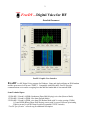
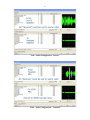
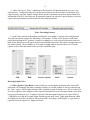
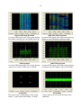
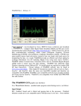
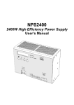
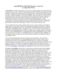
Doc Release 0.2
1-Sept-13
FreeDV Quick Start Guide
Here is a one page doc that should get you started on HF DV.
For detailed instructions, see the detailed document.
1. Hardware: For TX and RX, two sound devices are required. One internal sound card, a USB sound
interface -or- a transceiver with a built-in sound device will be used for the data. The second device may
be “Gamer” or equivalent USB headset for the voice I/O. Any modern PC with USB ports and a sound
card will work. If you just want to “listen to digital voice,” then only one soundcard/device is needed.
2. Install FreeDV with the Windows installer. Select the two sound devices and test them with Audio
Config tools. Next, select a conventional com port for PTT or a serial device using USB with Hamlib.
In Tools>Options, add your call sign/name/location. Keep this text entry as short as possible.
3. Radio DSP: Turn off TX and RX DSP processing. Think flat BP filters, no speech compression.
Turn off the radio’s TX monitor.
3. Tuning: Set the radio dial on frequency (try 14.236), then click on “Start.” FreeDV needs about 3dB
SNR to decode without voice dropouts. The small Red Marker at bottom of the Waterfall must be on the
BPSK Pilot tone carrier (normally at 1500Hz) to obtain sync. Use the mouse to move the Red Marker.
Do not retune once sync has been established. For more frequencies, visit http://qso.k7ve.org QSO
Finder.
4. Power: Run only 20% of the radio’s rated output. Peak power is much higher. Avoid ALC action.
5. Mode: Start with the default “1600.” It is more robust than 1400 for HF and only 150Hz wider.
6. Equalizer: Bring up the mid-range (treble) gain and lower the bass for the mic and speaker.
7. Voice decoding begins immediately after the received signal is “tuned in” (in sync). Expect sync
around 2dB SNR and good voice decoding around 4dB SNR. The higher, the better...
8. Squelch: Start with the default of 1.5 (dB).
9. Split operation allows changing the receive frequency without affecting the transmit frequency.
10. Analog mode bypasses DV and routes audio for SSB and analog frequency monitoring.
11. Videos: “Microsoft Windows Users Quick Start” and “Video Guide for Microsoft Windows Users”
are available at FreeDV.org Please take a few minutes and watch these instructional videos.
2
FreeDV…Digital Voice for HF
Detailed Document
FreeDV Graphic User Interface
FreeDV is a HF Digital Voice program for Windows, Linux and Apple utilizing an FDM modem
and the open source low bit rate CODEC2. Compatible with SSB radios, FreeDV provides
communications voice audio occupying less than half the bandwidth of conventional SSB.
Some Technical Specs:
1125Hz BW 50 baud 14 QPSK (Quadrature Phase Shift Keying) voice data (Narrow Mode)
1275Hz BW 50 baud 16 QPSK voice data (Default Mode)
2125Hz BW 50 baud 16 QPSK voice data (DX Robust Mode with 2x carrier spacing (150Hz)
1 Center BPSK (Binary Phase Shift Keying) carrier with 2x power Pilot tone/sync/tuning
25bit/s text rate for call ID/Name/Location (expanded G3PLX Varicode)
“FreeDV Specification” at freedv.org for additional description.
3
Tip: “Microsoft Windows Users Quick Start” and “Video Guide for Microsoft Windows Users” videos
are available for FreeDV. This is an excellent source of help for installing and operating FreeDV and
may be found at freedv.org Take a few minutes to view these before starting the setup.
PC
USB Headset
Radio to PC Interface
Hardware:
1. Sound card and PTT control setup is the same as other digital modes such as PSK31 except DV
requires a “Gamer” or equivalent USB headset for voice input and output As an alternative to
the headset, a second sound card with its mic/speaker may be used. Like other digital modes, a
Radio to PC interface either homemade or purchased is necessary to provide isolation and relay
control for PTT. To “listen only,” just one sound card is needed. After connecting/installing the
sound devices, identify and locate their associated Windows Mixers and slider controls. Adjust
these to mid-range as a starting point. Keep them handy so they will be easily accessible
throughout the installation. The mic Record mixer adjusts the audio level from the receiver and
the Playback mixer adjusts the audio to the transmitter. If currently using a digital mode such as
PSK31, the transmitter and receiver levels should be relatively close. Equally important is the
mixer slider controls for the USB headset since the mic and headphones will require adjustment.
2. FreeDV for Windows will execute and run on about any home or laptop PC with a dual core or
higher Intel/AMD CPU. Virtual Audio Cables (VAC) commonly used with SDR radios is
compatible. Dependent upon your hardware interface and radio, PTT rig control may be
configured for VOX, Hamlib or a serial port. Flex, HPSDR and other SDRs may use a virtual
com port pair.
Software:
Window files for FreeDV
3. Go to FreeDV.org then under Download, click on Windows binary files and execute the program.
This will install for Windows XP, 7, and 8 software including an uninstall file. The bin folder will
4
contain dll’s, freedv.exe, and the PTT Hamlib dll’s for CAT control. No other files will be created after
configured. No additional software needed. After installation, execute FreeDV from the start menu. For
other operating systems, see the listing under Download.
PC to Radio Interface Connections
4. For conventional SSB radios, connect the cables via RIGblaster instructions or equivalent
interface to the PC and Radio input/outputs. The radio’s or SignaLink™ USB port with Hamlib PTT
control may be used. Connect a USB headset to the PC for the voice I/O. If a separate sound card or
USB sound device is preferred over the headset, then install it with a mic and amplified speakers.
“Tools” Pull down Menu
5
PTT Configuration
5. Under Tools, go to “PTT Config” and select the Com Port for the radio’s PTT control
(recommended over use of VOX control). Either Hamlib PTT or conventional Serial Port Settings may
be used. Select the Serial Device or COM port for PTT DV. “RTS= +V” is normally used for rig
control. If the radio is keyed into transmit after clicking “Apply,” change the polarity. Then click OK. If
still does not control PTT, try DTR or combination of both.
Tools - Options
6. Under Tools, go to “Options.” Enter your call sign and any optional information (name, location,
etc.) This will be sent to the receiving station along with the voice. To test the flatness of the TX radio’s
filters, checking “Test Frames” sends data to the receiving station for evaluation using the “Test Frame
Error” window. Do not check this for normal DV contacts.
6
Tools - Audio Configuration – Receive
Tools - Audio Configuration – Transmit
7
7. Go to the Tools pull down menu and select “Audio Config.” Sound cards/USB adapters, VAC
and/or USB headsets installed on the PC will be listed. Select the PC’s internal sound card/USB
interface for the “From/To Radio” receive and transmit data. Select the USB headset for the “To
Speaker/Headphones – From Microphone” voice out and input. To test the selection, click on the “Rec
2s” tab, look for a 2 second deflection in the scope (from the radio’s speaker output audio or from
speaking into the mic). Next, click on the corresponding output device and listen for an 800Hz tone
followed by a deflection in the scope. If audio levels have not been previously set for use with another
digital mode like PSK31, then they will need adjusting to avoid over or under driving your MIC input of
your radio or overdriving the input of the sound card MIC or LINE IN. See “Receiving Digital Voice”
and “Transmitting Digital Voice” topics for these adjustments. API tab shows Port Audio info.
Note:
If you have a "9600" input and output on your radio (usually on a round DIN ACC connector), this is the
best connection for every digital mode. Your radio (usually in a menu) should be configured for 9600 or
"no pre-emphasis/de-emphasis" if it has this available. If the radio's configuration menu has a
1200/9600 setting, leave it permanently on 9600. If not available, FreeDV will still work fine with
Mic/speaker connections. FreeDV must be “stopped” to change Audio and PTT configurations
Tools - Filter and Equalizers
8
8. Under Tools, go to “Filter.” Adjustment of the Equalizer will depend upon the mic your voice
characteristics. Testing has found voice quality may be improved with most mics by raising the midrange frequency and Gain. Similar changes for the Speaker equalization may show improvements also.
Adjustment of the LPC Post Filter may be adjusted to improve the subjective speech quality. On-the-air
reports and experimentation will be needed to make final adjustments.
Tools - Recording Features
9. Under Tools, options for Recording and Playback are available. Currently, the record/playback
files (Mic in) must be sampled at 8 kHz using 16 bit samples. Off the air DV may be recorded and
played back through the PC speakers. Currently, recordings may not be played back into the radio mic
input. These dialog boxes will appear in the lower left hand corner below the options call sign/name text
box while running. The recordings are 30 seconds in length which is the same time as a DV signal
requires to move from the bottom to the top of the waterfall display.
SNR
BER
Receive Squelch
Mode
Control
Receiving Digital Voice:
10. SNR: (Signal to Noise Ratio) is shown both in a visual indicator and numerically. Since SNR
estimation will continually fluctuate (sometimes rapidly) over an HF channel, it can be averaged using
the “Slow” option. SNR of approximately 3dB is required to begin decoding voice. This is a rather low
level noisy signal so some dropouts can be expected. Dependent on your receiving location’s noise floor,
expect good decoding at S4-5. To judge the quality of the data signal being received, expect SNR of
>15dB while receiving an S9 signal (again, depends on your noise floor). Multi-path distortion, QRM
and fading obviously have an adverse effect on the SNR. Providing a “SNR Report” is a good way to
report the received signal level. Higher, the better…
9
11: Sync: The radio button appears when the received signal is in sync with the transmitter.
Sync is derived from the BPSK (binary phase shift keying) Pilot Tone signal in the center of the FDM
carriers. The small Red Marker at the bottom of the display (defaults at 1500 Hz) should be centered in
between the BPSK signal “tracks.” It can be within +/- 200Hz and still provide sync.
12. BER: (Bit Error Rate) is an end-to-end performance assessment of the transmitter, receiver and
the propagation between. BER is the percentage of errors defined by the formula:
13. Squelch: Checked box activates squelch with a default of 1.5dB. Experience has found decoding
of low SNR signals is possible in multipath/fades and QRM by taking advantage of the fast
recovery/sync of FreeDV. Experiment with the squelch level in different signal and noise conditions.
This setting correlates with the received signal SNR.
Spectrum Occupancy by Mode
14. Mode: 1400 V0.91 was the initial mode developed and is retained for compatibility. It is also the
narrowest mode (1125Hz) with 14 carriers but has no FEC within the CODEC2 so it is not as robust.
Normally on HF, 1400 should only be used for compatibility with early beta releases. 1600 mode is the
default and has 300 bits of FEC in CODEC2 allowing up to a 10% BER before falling apart. Experience
has shown that 95% of the QSOs are using this mode because of its robustness and narrow BW
compared with Wide. 1600 Wide (2125Hz) which has 2x (150Hz) carrier spacing helps combat the
effects of Doppler on long paths with severe deep multipath. It has been found effective for DX contacts
requiring multiple hops. On a busy band, 1600 Wide will be more susceptible to adjacent channel QRM.
15. Control: Start/Stop FreeDV must be in “Start” mode to begin receiving. With no FreeDV signal
present, the waterfall will display band noise indicating audio is being routed to FreeDV’s input. If no
noise is observed, slowly raise the audio level using Windows sound mixer (Recording MIC or LINE
IN) until the level is blue in color. A signal will have more amplitude and depending upon its strength,
the carriers will change color and become lighter blue to red. Strong interference (SSB) and strong noise
(QRN) will be red in color. PTT may be activated with either the mouse or toggling the PC spacebar.
10
Default 1600 Mode Waterfall
16 carrier FDM signal with 75Hz carrier spacing
Red marker showing sync on DQPSK Pilot tone
1600 Wide Mode Waterfall
16 carrier FDM signal with 150Hz carrier spacing
Change in color (amplitude) indicates fading
1600 Spectrum
16 carrier FDM signal with 75Hz carrier spacing
with sync on center of Pilot tone at 1500Hz
1600 Wide Spectrum
16 carrier FDM signal with 150Hz carrier spacing
to minimize adverse Doppler effect on DX paths
Scatter Plot
H/V points of the 4 QPSK phases with a “tight
cluster” = good signal while fading = X shape
From Radio
Carrier audio level received at the input of the
soundcard.
11
Audio to Speaker/Headphones
Level of audio feeding the USB headset or a
speaker. Adjust for max peaks < +/- 1
Timing Delta
Plot showing estimate of the best sampling time.
Changes indicate difference in TX/RX clock.
Frequency Delta
Frequency difference between receiving station
and transmitting station frequency.
Test Frame Errors
Display of a test frame received. Straight lines
are carriers with no errors. No signal on right.
Typical Win7 USB Headset
“Mixer” adjustments for
Voice Input and Output
(2nd sound device)
12
Multiple Signal Displays
Audio Level Indicator
16. Multiple Signal Displays: Various displays are available to view the received signal. The default
display is the waterfall. Click on the tabs below for more. On transmit; the “Frm Mic” scope is used for
showing input audio from the Mic. To add a display, left click on the display tab and drag it vertically to
the top. Next, release the left click button when a light blue background is showing. Displays can be
arranged in various horizontal and vertical positions. The waterfall color may be changed to
monochrome or all blue hues with a right click inside the display window. Dark areas (sometimes
called notches) indicate presence of multipath fading. Under these conditions (which are very common
on HF), the spectrum display will show the individual carriers (14 or 16) constantly changing in
amplitude.
17. To obtain sync with the transmitted signal, precise (<200Hz) tuning is required but easily
accomplished using the mouse for “click tuning” while observing the Waterfall or Spectrum displays.
First, tune the receiver dial to the operating frequency (try 14.236 USB). If a signal is present with an
SNR of at least 2-3dB, decoding should start when the Red Marker at the bottom of the display is within
the BPSK “tracks” (same waterfall appearance as PSK31) sync signal. If the Red Marker is not centered,
then move the mouse cursor to the center and left click. Instantly, the signal should sync and voice will
be decoded and sent to the headset or speakers. Once in sync, the radio’s frequency dial should not be
moved. FreeDV’s AFC will track small drifts of the signal. Normally, the sync should be centered in the
display at 1500 Hz to ensure the FDM signal for all modes is within the Tx/Rx band pass of the
transceiver.
18. The input level from the radio to FreeDV should be adjusted using the Mixer so the waterfall
FDM carriers are mostly blue to green in color. If too high, the “Level” bubble will flash a warning. A
slightly higher level may be needed for the Spectrum display. Stronger signals in the waterfall will
display the carriers in different shades of blue, green, and red. Multipath selective fading results in a
various darker “patterns” displayed in the waterfall as the amplitude of the carriers are being reduced.
13
Note: Window’s mixer “sliders” are used for all level adjustments. For SDR radios with Virtual Audio
Cables such as PowerSDR, use the application’s software adjustments (VAC Rx / Tx Gain).
Power Setting:
Keep ALC < 0
For typical 100w radio
run < 25w average power
Transmit Display (Microphone input level)
Transmitting Digital Voice:
19. First, verify the radio is operating full output on SSB. The final output drive will be set using the
sound device selected in Tools>Auto Config>Transmit>To radio. If not started, click on “Start” and
then “PTT.” Quickly, adjust the RF output level and then watch the ‘Frm Mic” display while speaking in
a normal voice. Adjust for 75% maximum deflection. Any voice input too high will cause clipping.
Adjust RF power for approximately 25w average with a 100w transceiver. This is an important setting to
avoid distortion and lowering SNR at the receiving station. If necessary, reduce the drive level for no
14
ALC action. With no voice input, the “thin” center baseline on the display should not show any
deflection... If it does, this indicates unwanted noise is being picked up (i.e. loud fans) within the ham
shack or from RF interference.
Note: The DV signal has a rather high peak-to-average-power (PAPR) ratio meaning the RF amplifier
needs additional “head-room” for the multi-carrier’s higher peak power. Otherwise these peaks will be
distorted and cause errors in the data sent to the CODEC2. The peaks are quite fast and a conventional
“peak reading” wattmeter will not accurately read them. The average power output should not exceed
20-25% of your SSB transmitter.
Tip: Call sign/name text data is being sent (repeated continuously during transmit) at a low bit rate
(25bit/sec). When initializing a contact, transmit for 10-15 seconds minimum to ensure the receiving
station receives your call and location in the text box.
Analog: (SSB)
20. Clicking on this button bypasses DV and routes mic and speaker audio for SSB. It may also be
used to quickly monitor the frequency for analog transmissions.
Other Features:
21. Split allows independent tuning of the RX frequency without affecting the transmitter’s
frequency. This is useful in three-ways and nets to avoid changing the transmit frequency for stations
entering the QSO not on the established frequency.
Text Box for Call ID/QTH info
22. The call sign/name/location text is sent in a continuous loop and displayed in the text box. Use
Tools>Options to enter your info for transmitting. The “Clear” button may be used to clear the box.
Operating Tips:
Where to Begin...
23. Start by looking for activity on 20m, 14.236 USB. FreeDV’s FDM carriers make a distinctive
noise but are half the width of SSB. Avoid confusing the digital EasyPal picture transfer OFDM signals
on 14.233 with DV. “FreeDV QSO Finder (http://qso.k7ve.org/) written by John, K7VE is available online for the DV community. Current stations on the air, frequencies in use and a chat line are available.
Just log on with your call sign and enter a frequency. The list of suggested frequencies is at the bottom
of the page. If you do not see them, some browsers may require you to pull the window down to display
the entire page. A call sign look up is available for stations logged in. Just click on their call sign.
Thank you, John!
15
Calling CQ…
24. Call sign/name text data is being sent (repeated continuously) at a low bit rate (25bit/sec) during
transmit. When calling CQ or initializing a contact (calling a station), transmit for 10-15 seconds
minimum to ensure the receiving station receives your call and location in the text box. Be sure to check
the FreeDV QSO Finder at http://qso.k7ve.org/
RFI and ambient shack noise and RFI…
25. RFI can cause noise and annoying sounds to be transmitted and decoded along with the voice. If
experienced, a few ferrites on the interface cables and at the mic input may help remove this annoyance
for the listener.
Voice quality is dependent on the type of microphone but low cost PC “electret” mics can provide good
voice audio. Logitech and Altec Lansing HS are known to work fine. The FreeDV equalizer can
improve the audio quality.
Minimize ambient noise pick up by lowering the mic level as low as possible while speaking in a
normal level close to the mic element. Loud fans or other non-voice audio in the background may be
picked up and transmitted as noise. Mics in PC cameras are generally not recommended. To check for
noise pickup, watch the center green base line on the Tx display when not speaking into the mic. It
should not show any deflection.
26. More information…
Want more information on FreeDV? Check freedv.org often and the links including David Rowe’s posts
at http://www.rowetel.com/blog/?page_id=452 Like FreeDV? Please consider a donation at freedv.org
for the developers.
Acknowledgements: Thanks to David Rowe, VK5DSG for his technical support, Bruce Perens, K6BP
for his inspiration and Rick Peterson, WA6NUT for his comments and review of the document.
Corrections/questions/additions/comments may be directed to: [email protected]
Mel Whitten, KØPFX
02-Sep-13 Rev 0.2