1
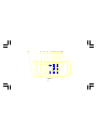
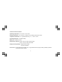
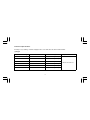
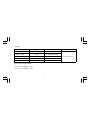
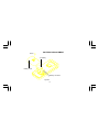
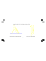
DIGITAL THERMOMETER OPERATOR’S MANUAL 53 206-3744 55 206-3750 DIGITAL THERMOMETER OPERATOR'S MANUAL RS53 206-3744 RS55 206-3750 2 INTRODUCTION 1-1 Unpacking and Inspection Upon removing your new Digital Thermometer from its packing, you should have the following items: 1. Digital Thermometer. 2. K-type Bead Thermocouple. 3. Operator's Manual. 4. Protective Holster. 5. Belt Clip. 1-2 Front Panel Refer to Figure 1 and the following numbered steps to familiarize yourself with the meter's front panel controls and connectors. 1. Digital Display Window — The digital display window has two 4-digit LCD readout (maximum reading 9999) display. 3 The upper display is for displaying the Stop Watch and MAX/MIN reading and has symbols for auto polarity, REC, MAX, MIN, E , °C and °F. The lower display is for displaying the reading measured and has symbols for auto polarity , HOLD, J, K, °C, °F, (TI, T2 and T1-T2 for 55 only). 2. Thermocouple Connectors — Allows connections of miniature thermocouple plugs. (2 for Model 55). 3. Hold Switch — Used to hold the numeric reading on main display. When pressed the HOLD annunciator is displayed. Conversions are made but the reading is not updated. 4. Power ON/OFF Switch — Turns the thermometer on or off. 5. Key — This key is used to control the timer. The timer is only enabled while the minor display is blanked. (The maximum reading is 99:99). When the first press is made, the is displayed and the timer starts from 00:00 and counts in one second intervals. Following presses toggle between stop and recounting. Press and hold this key for more than 2 seconds will disable the timer. 4 6. °C / °F Selector — This key switches between °C and °F. 7. MAX/MIN Key — Pressing this key enables the RECORD mode while the minor display is blacked. When first pressed the REC symbol will be displayed and the thermometer will continually record and update the maximum and minimum readings. To view the stored maximum reading, press this key once (the MAX symbol will appear). To view the stored minimum reading, press this key again (the MIN symbol will appear). Additional presses of this key toggle between MAX and MIN. Press and hold this key for more than two seconds will disable this mode. 8. T1 - T2 Switch — Selects the T1 - T2 mode for measuring. (55 only) 9. T2 Switch — Selects the T2 mode for measuring. (55 only) 10. T1 Switch — Selects the T1 mode for measuring. (55 only) 5 Figure 1 6 9 10 5 6 7 8 4 3 1 2 SPECIFICATIONS 2-1 General Specifications This thermometer conforms to the temperature / voltage tables of the National Bureau of Standards and to the IEC 584 Standards for K-type. Display : Two 4-digit Liquid Crystal Displays (LCD) with a maximum reading of 9999. Polarity Indication: Automatic, positive implied, negative indicated. Overrange Indication : "OL" or "-OL". Low Battery Indication : "" is displayed when the battery voltage drops below operating voltage. Reading Rate : 1 sec/reading nominal. (53 only). T1 or T2 mode 1 sec/reading nominal. (55 only). T1-T2 mode 2 sec/reading nominal. (55 only). 7 2-2 Environmental Conditions Operating Temperature : 0°C to 50°C, 0 to 75% R.H. Storage Temperature : -20°C to 60°C, 0 to 80% R.H. with battery removed from meter. Temperature Coefficient : 0.1 x (Specified accuracy) / °C, < 18°C or > 28°C. Power Requirements : 9V Alkaline battery. Battery Life : Alkaline 90 hours Dimensions (H x W x D): 160mm x 64mm x 26mm without holster. 170mm x 74mm x 39mm with holster. Weight (including battery) : 300gms without holster 430 gms with holster. Accessories : 2 K-type bead thermocouples (55), 1 K-type bead thermocouple (53), battery (installed), operator's manual and protective holster. 8 2-3 Electrical Specifications Accuracy is ± (% reading + number of digits) at 23°C ± 5°C less than 75% R.H for thermometer. (1) K-type Measurement Range Resolution Accuracy -200°C ~ -100°C 0.1°C ± (0.3% reading + 1°C) -328°F ~ -148°F 0.2°F Input Protection ± (0.3% reading + 2°F) -99.9°C ~ 999.9°C 0.1°C ± (0.1% reading + 0.7°C) -147.8°F ~ 999.9°F 0.2°F ± (0.1% reading + 1.4°F) 1000°C ~ 1370°C 1°C ± (0.3% reading + 1°C) 1000°F ~ 2498°F 2°F ± (0.3% reading + 2°F) 60V d.c. or 24 Vr.m.s. 9 (2) J-type Measurement Range Resolution Accuracy -200°C ~ -100°C 0.1°C ± (0.3% reading + 1.1°C) -328°F ~ -148°F 0.2°F ± (0.3% reading + 2.2°F) -99.9°C ~ 760°C 0.1°C ± (0.1% reading + 0.8°C) -147.8°F ~ 999.9°F 0.2°F ± (0.1% reading + 1.6°F) 1000°F ~ 1400°F 2°F ± (0.3% reading + 2°F) (3) T1 - T2 (K-, J-type), 55 only ± (0.3% of T1-T2 reading + 2.0°C) ± (0.3% of T1-T2 reading + 4.0°F) 10 Input Protection 60V d.c. or 24 Vr.m.s. (4) THERMOCOUPLE CHARACTERISTICS: (A) 50BK bead thermocouple: 1. Temperature Range : -40°C to 204°C (-40°F to 399.2°F). 2. Tolerances : ± (2.2°C or 0.75%) from 0°C to 204°C. ± (2.2°C or 2.0%) from 0 to -40°C. 3. Wire Length : 1m, with miniature plug. Teflon tape insulated. (B) 50BJ bead thermocouple: 1. Temperature Range : -40°C to 204°C (-40°F to 399.2°F) 2. Tolerances : ± (2.2°C or 0.75%). 3. Wire Length : 1m, with miniature plug. Teflon tape insulated. 11 OPERATION This instrument is designed to use external K-type or J-type thermocouple as temperature sensor. Temperature indication follows National Bureau of Standards and IEC 584 temperature / voltage tables for K-type or J-type thermocouple are supplied with the thermometer. WARNING TO AVOID ELECTRICAL SHOCK, DO NOT USE THIS INSTRUMENT WHEN VOLTAGES AT THE MEASUREMENT SURFACE EXCEED 24V r.m.s AC OR 60V DC. TO AVOID DAMAGE OR BURNS, DO NOT MAKE TEMPERATURE MEASUREMENTS IN MICROWAVE OVENS. 3-1 Preparation and Caution before Measurement 1. Before measurement, warm up for at least 30 seconds, after connecting the thermocouple to the thermometer. 2. If the instrument is used near noise generating equipment, be aware that the display may become unstable or indicate large errors. 12 3-2 Temperature Measurements 1. Connect the plug of the thermocouple to the connector of the thermometer. 2. Select the desired input mode and °C/°F. 3. Use the sensing point of thermocouple to measure the surface to be measured. 4. Read the stable reading. 5. "Warning: Do not measure the surface if the potential exceeds 60Vd.c. or 24Vr.m.s." 3-3 How to change to J-type mode 1. Set the thermometer to "OFF" condition. 2. Press the ON/OFF key and HOLD key at the same time. 3. Unpress the ON/OFF key but keep the HOLD key depressed for at least 2 seconds and then release it, the thermometer goes to the J-type mode. 4. In this mode, the J symbol is displayed and the K symbol is blanked. 5. To revert back to K-type mode, switch the instrument OFF and ON again. 13 MAINTENANCE To keep the instrument clean, wipe the case with a damp cloth and detergent, do not use abrasives or solvents. Any adjustment, maintenance and repair shall be made by a skilled person. To maintain the thermocouple in good condition, observe the following precautions: — Avoid excess bending. — Do not overheat the thermocouple. — Avoid chemical reactions that can damage the thermocouple. BATTERY REPLACEMENT The meter is powered by a single 9V battery. Refer to Figure 2 and use the following procedure to replace the battery: 1. Turn the meter off. Remove the thermocouple connector. 2. Remove the holster. 3. Position the meter face down. Remove the screw from the battery cover. 4. Remove the battery cover. 5. Lift the battery from case top, and carefully disconnect the battery from battery connector leads. 6. Install a new battery. 7. Replace the battery cover. Reinstall the screw and replace the holster. 14 BATTERY REPLACEMENT Screw 9V battery Battery cover Battery connector Figure 2 15 HOW TO USE THE TILT STAND AND HOLSTER Swing the stand out for easier meter reading. Hang on a nail at the workbench. 16 United Kingdom Italy RS Components UK PO Box 99, Corby Northants NN17 9RS Tel 01536 201234 Fax 01536 405678 RS Components S.p.A. Via Cadorna 66 20090, Vimodrone, Milano Tel +39 2/27,425.1 Fax+39 2/27,425.207 France Germany Radiospares Composants Rur Norman King, BP 453 60031 Beauvais Cedex Tel +33 3 44 10 15 15 Fax +33 3 44 10 16 00 RS Components GmbH Hessenring 13b 64545 Morfelden-Walldorf Tel +49 6105/401 –234 Fax +49 6105/401-100