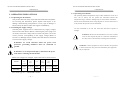
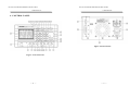
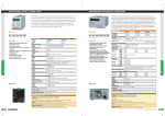
1
IPS-3201/3202 PROGRAMMABLE POWER SUPPLY IPS-3201/3202 PROGRAMMABLE POWER SUPPLY USER MANUAL USER MANUAL CONTENTS PAGE 1. PRODUCT INTRODUCTION.......................................................................................1 Programmable Power Supply 1-1. DESCRIPTION............................................................................................................1 1-2. FEATURES..................................................................................................................2 IPS-3201/3202 2. TECHNICAL SPECIFICATIONS ................................................................................3 3. OPERATING PRECAUTIONS .....................................................................................6 3-1. UNPACKING THE INSTRUMENT ........................................................................6 3-2. CHECKING THE SUPPLY VOLTAGE..................................................................6 3-3. OPERATING ENVIRONMENT...............................................................................7 User Manual 4. CONTROL PANEL..........................................................................................................8 5. OPERATION .................................................................................................................. 12 RS Components Ltd This manual contains proprietary information, which is protected by copyrights. All rights are reserved. No part of this manual may be photocopied, reproduced or translated into another language without prior written consent of RS Components. The information in this manual was correct at the time of printing. Due to product improvements, RS Components reserves the rights to change specification, equipment, and maintenance procedures at any time without notice. 5-1. OUTPUT VOLTAGE AND CURRENT SETTING ............................................ 12 5-2. OVER VOLTAGE AND OVER CURRENT PROTECTION SETTING.......... 13 5-3. VOLTAGE AND CURRENT STEP SETTING: .................................................. 14 5-4. INFORMATION STORING AND RECALLING:............................................... 15 5-5. INFORMATION EDITING AND COPYING:..................................................... 16 5-6. AUTO-OPERATION............................................................................................... 17 5-7. PARALLEL OPERATION MODE........................................................................ 19 5-8. TRACKING OPERATION MODE........................................................................ 19 5-9. RS-232 INTERFACE PARAMETER SETTING.................................................. 20 5-10. MAXIMUM OUTPUT SETTING VALUES...................................................... 21 5-11.TEST LEADS .......................................................................................................... 21 5-12. REMOTE CONTROL VIA THE RS-232 INTERFACE.................................... 21 6. MAINTENANCE ........................................................................................................... 22 6-1. FUSE REPLACEMENT.......................................................................................... 22 6-2. LINE VOLTAGE ADJUSTMENT ........................................................................ 22 6-3. CLEANING .............................................................................................................. 23 6-4. REPAIR AND CALIBRATION............................................................................. 23 82IP-32020MA – i – – i – IPS-3201/3202 PROGRAMMABLE POWER SUPPLY IPS-3201/3202 PROGRAMMABLE POWER SUPPLY USER MANUAL USER MANUAL SAFETY TERMS AND SYMBOLS FOR UNITED KINGDOM ONLY These terms may appear in this manual or on the product: NOTE: This lead/appliance must only be wired by competent persons WARNING. Warning statements identify condition or practices that could result WARNING: THIS APPLIANCE MUST BE EARTHED in injury or loss of life. IMPORTANT: The wires in this lead are colour-coded in accordance with the following code: CAUTION. Caution statements identify conditions or practices that could result in damage to this product or other property. Green/ Yellow: Blue: Brown: WARNING: This equipment is not for measurements performed for CAT II, III Earth Neutral Live (Phase) and IV. Measurement category I is for measurements performed on circuits not directly connected to As the colours of the wires in main leads may not correspond with the colour markings identified in your plug/appliance, proceed as follows: MAINS. Measurement category II is for measurements performed on circuits directly connected to the low voltage installation. Measurement category III is for measurements performed in the building installation. The wire which is coloured Green & Yellow must be connected to the Earth terminal marked with the letter E or by the earth symbol or coloured Green or Green & Measurement category IV is for measurements performed at the source of the low-voltage Yellow. installation. The wire which is coloured Blue must be connected to the terminal which is marked with the letter N or coloured Blue or Black. The following symbols may appear in this manual or on the product: The wire which is coloured Brown must be connected to the terminal marked with the letter L or P or coloured Brown or Red. DANGER ATTENTION Protective Earth (ground) High Voltage refer to Manual Conductor Terminal Terminal – ii – Frame or Chassis Terminal If in doubt, consult the instructions provided with the equipment or contact the supplier. This cable/appliance should be protected by a suitably rated and approved HBC mains fuse: refer to the rating information on the equipment and/or user instructions for details. As a guide, cable of 0.75mm2 should be protected by a 3A or 5A fuse. Larger conductors would normally require 13A types, depending on the connection method used. – iii – IPS-3201/3202 PROGRAMMABLE POWER SUPPLY USER MANUAL IPS-3201/3202 PROGRAMMABLE POWER SUPPLY USER MANUAL Any moulded mains connector that requires removal or replacement must be destroyed by removal of any fuse & fuse carrier and disposed of immediately, as a plug with bared wires is hazardous if a engaged in live socket. Any re-wiring must be carried out in accordance with the information detailed on this label and in 1. PRODUCT INTRODUCTION accordance with local regulations. If further information is required, contact the 1-1. Description The IPS series programmable power supplies are controlled by a supplier, the address is given at the end of these instructions. Microprocessor Unit (MPU), which can be connected via an in-built RS-232 communication interface to a personal computer. This allows remote operation for automatic testing and control as may be required by the user. The voltage and current are controlled by a 12 bit D/A converter with high resolution and accuracy. The digital control of the system allows simple and precise entry of information, together with clear and unambiguous monitoring of the instrument parameters. The over-voltage protection (OVP) and over-current protection (OCP) is set through software and detected by hardware to provide continuous protection for the instrument, external circuits and the user. – iv – – 1 – IPS-3201/3202 PROGRAMMABLE POWER SUPPLY IPS-3201/3202 PROGRAMMABLE POWER SUPPLY USER MANUAL 1-2. Features 1) Digital control and programmable interface with high resolution and precision. 2) The 192×128 point LCD display can show multiple settings and measurement results simultaneously. The display format may be USER MANUAL 2. TECHNICAL SPECIFICATIONS SPECIFICATIONS Voltage Output Current OVP changed to suit individual requirements. 3) Intuitive interface window display allows convenient operation Current Voltage IPS-3201 IPS-3202 0-32V×3 0-32V×2, 0-6V×1 0-1A×3 0-2A×2, 0-5A×1 0-33V×3 0-33V×2, 0-7V×1 ≦3mV(≦5mV rating current>3.0A), test points are at the +output terminal and –output terminal point. ≦3mA(≦5mA rating current>3.0A), test points are at the +output terminal and –output terminal point. ≦3mV, test points are at the +output terminal and –output terminal point. ≦3mA, test points are at the +output terminal and –output terminal point. 10mV 1mA(2mA rating current>3.0A) 10mV ≦0.05%+20mV ≦0.1%+5mA(+10mA rating current>3.0A) ≦0.05%+20mV Ripple≦1mVrms/3mVp-p Noise≦2mVrms/30mVp-p ≦3mArms(≦5mArms rating current>3.0A) ≦100ppm+3mV Current ≦100ppm+3mA Voltage Current 10mV 1mA(2mA rating current >3.0A) 10%~90% ≦100ms 90%~10% ≦100ms (≧10% rating load) Voltage Load effect of the instrument. Current 4) High stability and low drift. 5) Over voltage, over current and over temperature protection. 6) Intelligent fan speed control Voltage Source effect Current 7) Warning signals via built-in buzzer. 8) 1/2 rack width for convenient rack installation. 9) Rotary knob for fine and coarse adjustment of settings. Setting resolution 10) 100 groups of memories for storing settings. 11) Parallel and series operation modes. 12) Programmable internal timer for output ramp-up, dwell & ramp-down operation. Program accuracy (25±5℃) Ripple & noise (20Hz~20MHz) Temperature coefficient (0~40℃) Readback resolution Response time; Voltage up Voltage down 2 Voltage Current OVP Voltage Current OVP Voltage 3 IPS-3201/3202 PROGRAMMABLE POWER SUPPLY IPS-3201/3202 PROGRAMMABLE POWER SUPPLY USER MANUAL Readback temperature Coefficient Drift Tracking operation USER MANUAL Voltage ≦100ppm+10mV Current ≦150ppm+10mA Voltage Current ≦100ppm+10mV ≦150ppm+10mA Tracking error ≦0.1%+20mV Series (Load effect) ≦20mV Voltage≦0.05%+20mV Current≦0.1%+10mA OVP≦0.05%+20mV Voltage≦3mV(≦5mV rating current>3.0A) Load effect Current≦6mA, test points are at the +output terminal and –output terminal point. Voltage≦3mV,Current≦6mA, test points are Source effect at the +output terminal and –output terminal point. Store/Recall points 0~99 Program accuracy Parallel operation Memory Setting time Timer Interface Power source Power consumption Mechanical specifications SPECIFICATIONS Operating environment IPS-3201 IPS-3202 Indoor use only Altitude: up to 2000 metres Ambient temperature: To satisfy specifications: 10℃ to 35℃ ( 50° F to 95°F ) Maximum operating range: 0℃ to 40℃( 32°F to 104°F ) Relative humidity: 85% RH(max.), non condensing Installation Category: II Pollution degree: 2 Storage temperature & humidity -10° to 70℃, 70%RH (maximum) Supplied accessories Power cable................……….. × 1 Instruction manual……………..× 1 Programming manual............... × 1 Test leads…..….………………. × 3 0.1sec~99min59sec(max×100) Resolution 0.1sec Function For output working loop (Auto-step running) RS232, GPIB interface option 100, 120, 220V±10%, 230V +10%/-6% 50/60Hz. AC IPS-3201: 210W IPS-3202: 360W Dimensions 230(W)×140(H)×380(D) mm. Weights 10 kg 4 5 IPS-3201/3202 PROGRAMMABLE POWER SUPPLY IPS-3201/3202 PROGRAMMABLE POWER SUPPLY USER MANUAL USER MANUAL 3-3. Operating environment 3. OPERATING PRECAUTIONS The operating ambient temperature range of this instrument is from 0° to 3-1. Unpacking the instrument The product has been fully inspected and tested before shipment. On receiving the instrument, please unpack and inspect it for damage caused during transportation. If any sign of damage is found, notify the bearer and/or the supplier immediately. 40°C (32° to 104°F). Do not operate the instrument outside this 3-2. Checking the supply voltage The IPS power supplies can be connected to any supply voltages shown in the table below. Before connecting the power plug to an AC outlet, ensure the voltage selector on the rear panel is set to the correct position corresponding to the supply voltage (Refer to section 6-2). Damage may be caused to the instrument if connected to an incorrect supply voltage. Use the instrument in an area free from dust and direct exposure to WARNING. To avoid electrical shock the power cord protective grounding conductor must be connected to ground. temperature range, otherwise damage may be caused to the instrument. Do not use the instrument where strong magnetic or electric fields exist, as it may disturb the operation of the instrument. sunlight. WARNING. Do not use the instrument in wet areas or where water or other liquids may fall on or enter the instrument, as this may cause a shock hazard or damage the instrument. WARNING. If this equipment is used in a manner not specified in these instructions, the protection afforded by the equipment may be impaired. WARNING. To avoid personal injury, disconnect the power cord before removing the fuse holder. When line voltages are changed, replace the fuses as shown below: Model Line Input Range Fuse Line Input voltage Range Fuse voltage IPS-3201 IPS-3202 T3A 100V 90-110V 250V 120V 108-132V T5A 250V T1.6A 220V 198-242V 250V 230V 216-253V T2.5A 250V Note: Fuse type is 5 × 20mm HBC ceramic. 6 7 IPS-3201/3202 PROGRAMMABLE POWER SUPPLY USER MANUAL IPS-3201/3202 PROGRAMMABLE POWER SUPPLY USER MANUAL 4. CONTROL PANEL Figure 4-2 Rear Panel Figure 4-1 Front Panel 8 9 IPS-3201/3202 PROGRAMMABLE POWER SUPPLY IPS-3201/3202 PROGRAMMABLE POWER SUPPLY USER MANUAL 1. Power switch 2. Display 3. 4. 5. 6. 7. +Output terminal -Output terminal GND terminal Rotary encoder V set (CH1) 8. I Set (CH2) 9. OVP Set (CH3) 10. F/C (STEP) 11. Recall△ (Store) 12. Recall▽(Recall) 13. AUTO (PARA/INDEP) Turns the AC power on to the instrument.. Indicates the setting of voltage and current values, output voltage and current value and the instrument and output status. Positive output terminal. Negative output terminal. Ground terminal connected to instrument chassis. Variable control knob. Output voltage setting. Switch to channel 1 by pressing [SHIFT][CH1] to enable setting of group parameters. Output current setting. Switch to channel 2 by pressing [SHIFT][CH2] to enable setting of group parameters. Over voltage protection value setting. Switch to channel 3 by pressing [SHIFT][CH3] to enable setting of group parameters. Allows coarse or fine adjustment selection for the rotary control knob. Press [SHIFT][STEP] to select. Recall the next set of stored information. Press [SHIFT][STORE] to store and edit information. Recall the previous set of stored information. Recall the highlighted stored information or set the range of information to recall automatically by pressing [SHIFT][RECALL]. Turn on/off automatic operation function by setting the AUTO on or off. Operate the instrument in parallel mode by pressing [SHIFT][PARA]. Return to independent mode by pressing the keys again. 10 USER MANUAL 14. Delay Set the voltage and current output delay time in (TRACK/INDEPT) automatic operation mode. Operate the instrument in series mode by pressing [SHIFT][TRACK]. Return to independent mode by pressing the keys again. 15. OCP Turn the over current protection on or off. (OVP RESET) Reset the over voltage protection mode by pressing [SHIFT][OVP RESET]. 16. SHIFT Second function selection. 17. Local Clear the remote control mode from RS232 and enable front panel control. 18. Contrast Press [SHIFT][CONTRAST] to adjust the contrast of the display. 19. Press [SHIFT][ ] to turn the buzzer on or off. 20. W Press [SHIFT][W] to change the character size. 21. I△ Press [SHIFT], then press I△ to increment one step of the output current. I▽ Press [SHIFT], then press I▽ to decrement one step of output current. V△ Press [SHIFT], then press V△ to increment one step of output voltage. V▽ Press [SHIFT], then press V▽ to decrement one step of output voltage. 22. Output Turn on or off output by pressing the button. 23. 0~9, “˙”, ENTER Value input. 24. AC power socket AC mains power input connector. 25. AC select switch Select mains supply voltage to 100V, 120V, 220V or 230V, 50/60Hz AC. 26. Cooling fan Internal cooling fan air outlet. 27. Interface connector RS-232C serial communication interface connector . 11 IPS-3201/3202 PROGRAMMABLE POWER SUPPLY USER MANUAL 5. OPERATION 5-1. Output voltage and current setting Press [SHIFT][CHx] to select the required output channel. The cursor will be set to CHx (x=1, 2 or 3). Refer to the drawing below: --Output voltage setting: Method 1: Press [V SET] and use the numeric keypad to enter the voltage value then press [ENTER]. Method 2: Press [V SET] and use the rotary knob to select the required voltage value and the output voltage setting will be changed. Press [ENTER] to terminate the voltage setting. Using this method, the output voltage will change immediately following the input value through the rotary knob. Example: Set voltage at 32.00V. Press [V SET][3][2][.][0][0][ENTER] --Output current setting: Method 1: Set output current by pressing [I SET] and using numeric keypad to enter the required current value and press [ENTER]. 12 IPS-3201/3202 PROGRAMMABLE POWER SUPPLY USER MANUAL Method 2: Press [I SET] and use the rotary knob to select the required current value and the output current setting will be changed. Press [ENTER] to terminate the current setting. Using this method, the output current will be changed immediately following the input value through the rotary knob. Example: Set current at 1.000A. Press [I SET][1][.][0][0][0][ENTER] When the load current through output terminal exceeds the setting value, the instrument then operates in constant current mode. If the load current remains below the set value, the instrument operates in constant voltage mode. 5-2. Over voltage and over current protection setting Press [SHIFT][CHx] to select the required output channel. The cursor is set to CHx (x=1, 2 or 3). --Over voltage protection setting: Method 1: Set OVP voltage level by pressing [OVP SET] and use numeric keypad to enter the required voltage value, then press [ENTER]. Method 2: Press [OVP SET], use the rotary knob to select the required voltage value and the OVP voltage setting will be changed. Press [ENTER] to terminate the OVP voltage setting. Using this method, the OVP setting will change immediately following the input value through the rotary knob. Example: Set OVP voltage at 33.00V. Press [OVP SET][3][3][.][0][0][ENTER] 13 IPS-3201/3202 PROGRAMMABLE POWER SUPPLY USER MANUAL --OVP status clear: When the output voltage exceeds the set 33.00V OVP value, the output will turn off. The instrument will enter OVP mode and the display will show “Over voltage protection”. Press [SHIFT][OVP RESET] to clear the OVP state and return to normal operation. --Over current protection setting: The OCP of each channel may be set individually by pressing [OCP]. If OCP is on, when the output current for the channel equals or exceeds the set current value, the output of the instrument will turn off. The instrument will enter OCP mode and the display will show “Over current protection”. Press [OCP] to clear the OCP state and return to normal operation. 5-3. Voltage and current step setting: Press [SHIFT][STEP] to enter into the item selection menu. Use the rotary knob to set the cursor to the item which is to be modified. Use the keypad to enter the required value and press [ENTER]. Store the setting by using the knob to move the cursor to [SAVE], then press [ENTER] again to complete the setting and storing. To cancel the setting, move the cursor to [EXIT] and press [ENTER] to terminate the setting without storing. 14 IPS-3201/3202 PROGRAMMABLE POWER SUPPLY USER MANUAL Example:Set the step voltage of Channel 1 at 1.00V and the step current at 0.10A. Press [SHIFT][STEP], select CH1 voltage and enter [1][.][0][0][ENTER]. Select CH1 Current and enter [0][.][1][0][0][ENTER]. Finally, use the knob to move the cursor to [SAVE] and press [ENTER] to complete the setting and storing. Note: The setting of the step voltage and step current of CH1 CH2 CH3 can be set using the same display window. 5-4. Information storing and recalling: --Information storing: Press [SHIFT][STORE] to enter item selection menu. Use the rotary knob to set the cursor to [STORE] and press [ENTER]. The memory store menu will appear. Use the numeric keypad to enter the store address and press [ENTER] to complete the store. Example:The current setting store address of the instrument is “00”. Press [SHIFT][STORE] to enter the item selection menu. Use the rotary knob to set the cursor to [STORE], then press [ENTER] and input [0][0][ENTER] to complete the store. --Information recall: Press [SHIFT][RECALL] to enter the item selection menu. Use the rotary knob to set the cursor to [Recall Memory] and press [ENTER] to display the memory recall menu. Enter the recall address by using the numeric keypad and press [ENTER] to complete the recall. 15 IPS-3201/3202 PROGRAMMABLE POWER SUPPLY USER MANUAL Example: Recall the store address “00” to the current status of the instrument. Press [SHIFT][RECALL] to enter the item selection menu and use the knob to set the cursor to recall memory. Press [ENTER] and input [0][0][ENTER] to complete the recall setting. 5-5. Information editing and copying: --Information Editing (Edit): Press [SHIFT][STORE] to enter the item selection menu and use the rotary knob to set the cursor to [Edit]. Press [ENTER] to display the memory editing menu, enter the address to edit using the numeric keypad and press [ENTER] to display the edit selection menu. Use the rotary knob to set the cursor to the item to edit, enter the new value or on/off status by using the number keys and press [ENTER] to confirm the change. After the modification is completed, set the cursor to [End] using the rotary knob and press [ENTER] to complete the setting. If required, continue with other setting changes by returning to the previous menu and repeating above procedures. When modification is complete, use the knob to set the cursor to [SAVE] and press [ENTER] to complete the edit session. To cancel changes, set the cursor to [Exit] and press [ENTER] to terminate the session without storing the changes. 16 IPS-3201/3202 PROGRAMMABLE POWER SUPPLY USER MANUAL --Information copying: Press [SHIFT][STORE] to enter item selection menu, select copy and press [ENTER] to enter the copy setting menu. Select the modified item, enter copy address and press [ENTER]. After modification, select [Save] and press [ENTER] to complete the setting. To cancel changes, set the cursor to [Exit] and press [ENTER] to terminate the setting without storing. Note: Do not repeat the address of source and target input. The value of the end setting must be larger than of the start setting. 5-6. Auto-operation. --Delay time setting: Press [DELAY] to enter item selection menu and use the rotary knob to set cursor to the required setting item. Enter the required time using the numeric keypad and press [ENTER]. Finally use the rotary knob to set the cursor to [End] and press [ENTER] to complete the setting. The delay time setting must also be stored in the specific location of the memory address according to the procedure of 5-4 “Information storing”. Note; when the store procedure is in operation, all the other settings of the instrument 17 IPS-3201/3202 PROGRAMMABLE POWER SUPPLY USER MANUAL will be also stored in the same memory address. To cancel changes, set the cursor to [Exit] by using the rotary knob and press [ENTER] to terminate the setting without storing. --Auto-operation Press [SHIFT][RECALL] to enter item selection menu, use the rotary knob to set the cursor to recall range and press [ENTER] to display the auto operation menu. Set the cursor to the item to be modified by using the rotary knob. Use the numeric keypad to input the auto operation setting value and press [ENTER]. After modification, use the knob to set the cursor to [Save], and press [ENTER] to complete the setting. To cancel the changes, set the cursor to [Exit] by using the rotary knob and press [ENTER] to terminate the setting without storing. Note: When the auto operation value is set to “00”, the operation will continually cycle until cancelled. 18 IPS-3201/3202 PROGRAMMABLE POWER SUPPLY USER MANUAL 5-7. Parallel operation mode Press [SHIFT][PARA] to enter the parallel operation mode. In this mode, the output voltage and current are controlled by channel 2. The selectable range of output voltage is the same as channel 2 under normal independent operation, but the settable range of output current is twice that of channel 2 under normal independent operation. Example: (1) Channel 1: Voltage=10V, Current= 1A. (2) Channel 2: Voltage=20V, Current= 2A. (3) Press [SHIFT][PARA] to enter parallel mode. (4) Output voltage=20V, output current=4A. 5-8. Tracking operation mode Press [SHIFT][TRACK] to enter tracking operation mode. In this mode, output voltage and current are controlled by channel 2. The selectable range of output voltage is same as channel 2 under normal independent operation, but the output currents can have different values. Example: (1) Channel 1: Voltage=10V, Current= 2A. (2) Channel 2: Voltage=20V, Current= 2A. (3) Press [SHIFT][TRACK] to enter tracking mode. (4) Output voltage=40V, output current=2A WARNING. A voltage of more than 60V DC presents a lethal shock hazard. Take extreme care when connecting power supplies in series to achieve voltages greater than 60VDC total, or 60VDC between any connection and earth ground. 19 IPS-3201/3202 PROGRAMMABLE POWER SUPPLY IPS-3201/3202 PROGRAMMABLE POWER SUPPLY USER MANUAL 5-9. RS-232 Interface parameter setting Press [SHIFT][RS-232] to enter item selection menu. Use the rotary knob to set the cursor to interface and press [ENTER] to display the interface selection menu. Set the cursor to the item to be modified by using the rotary knob and press [ENTER]. Set the cursor to address or Baud Rate setting as required. To modify the address, use the numeric keypad to enter the address value and press [ENTER]. To modify the Baud Rate, first press [ENTER], then use the rotary knob to set the cursor to the setting value to be modified and press [ENTER]. Finally set the cursor to [Save] by using the rotary knob and press [ENTER] to complete changes. To cancel the changes, set the cursor to [Exit] by using the rotary knob and press [ENTER] to terminate the setting without storing. USER MANUAL 5-10. Maximum output setting values MODEL ITEM Output voltage Output current Over-voltage Step voltage Step current Delay time Memory groups IPS-3201 CH1 33V 1.1A 34V 10V 0.5A CH2 33V 1.1A 34V 10V 0.5A 99’59” 100 IPS-3202 CH3 33V 1.1A 34V 10V 0.5A CH1 33V 2.1A 34V 10V 1A CH2 33V 2.1A 34V 10V 1A 99’59” 100 CH3 7V 5.2A 8V 1V 2.5A 5-11.Test leads Test leads supplied are suitable for the currents and channels as shown in the following table: MODEL ITEM Example: Set the RS-232 Baud Rate to 9600. Press [SHIFT][RS-232] to enter item selection menu. Use the rotary knob to set the cursor to interface and press [ENTER] to display the interface selection menu. Set the cursor to RS-232 by using the rotary knob and press [ENTER]. Use the knob to set the cursor to [Baud Rate] and press [ENTER]. Set the cursor to [9600] and press [ENTER]. Finally set the cursor to [Save] and press [ENTER] to complete the setting and storing. IPS-3201 CH1 CH2 (3A) (3A) Test Test Lead Lead Note: When using IPS-3202 4A-10A test lead. IPS-3202 CH3 CH1 CH2 CH3 (3A) (3A) (3A) (4A-10A) Test Test Test Test Lead Lead Lead Lead in parallel output mode, use the 5-12. Remote control via the RS-232 interface The IPS-series programmable power supplies can be remotely controlled via the RS-232 interface. Refer to the IPS-series Programming Manual for details of command strings and control options available. 20 21 IPS-3201/3202 PROGRAMMABLE POWER SUPPLY IPS-3201/3202 PROGRAMMABLE POWER SUPPLY USER MANUAL 6. MAINTENANCE 6-1. Fuse replacement WARNING. Disconnect power cord before replacing fuse. For continued fire protection, replace the fuse only with the specified type and rating. If the fuse blows, the display will not light and the power supply will not operate. During normal use, the fuse will not fail unless a fault has developed in the instrument. Replace the fuse only with one of the correct rating and type (refer to 3-2). The fuse is located on the rear panel (see Fig.4-2). 6-2. Line voltage adjustment The primary winding of the power transformer is tapped to permit operation from 100, 120, 220, or 230VAC, 50/60 Hz supply voltage. Conversion from one line voltage to another is achieved by changing the AC voltage selectors on the rear panel. The rear panel identifies the line voltage to which the unit was factory set. To convert to a different line voltage, proceed as follows: (1) Ensure the AC power cord is unplugged. (2) Use a small flat-blade screwdriver to change the AC selector switches to the desired supply voltage position. (3) A change in line voltage may also require a corresponding change of fuse value. Fit the correct fuse rating as indicated on the rear panel. (4) Connect the AC power cord, turn the instrument on and check for correct operation. 22 USER MANUAL 6-3. Cleaning To clean the power supply, use a soft cloth dampened in a solution of mild detergent and water. Do not spray cleaner directly onto the instrument, since it may leak into the cabinet and cause damage. Do not use chemicals containing benzine, benzene, toluene, xylene, acetone, or similar solvents. Do not use abrasive cleaners on any portion of the instrument. 6-4. Repair and calibration Servicing and repairs should only be undertaken by competent persons using correct components, equipment and procedures. To maintain accuracy, the instrument should be calibrated yearly. Contact the supplier or RS Components for details of repairs and calibration services. The address is given at the end of these instructions. 23 IPS-3201/3202 PROGRAMMABLE POWER SUPPLY USER MANUAL United Kingdom RS Components UK PO Box 99, Corby Northants NN17 9RS Tel 01536 201234 Fax 01536 405678 Italy RS Components S.p.A. Via De Vizzi 93/95 20092 Cinisello Balsamo, Milano Tel+39 2/66,058.1 Fax+39 2/66,058.051 France Radiospares Composants Rur Norman King, BP 453 60031 Beauvais Cedex Tel +33 3 44 10 15 15 Fax +33 3 44 10 16 00 Germany RS Components GmbH Hessenring 13b 64545 Morfelden-Walldrof Tel +49 6105/401-234 Fax +49 6105/401-100 Spain Amidata S.A. Avenida de Europa, 19, 28224 - Pozuelo de Alarcón – Madrid Teléfono 902 100 711 Fax 902 100 611 24