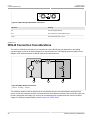
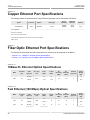
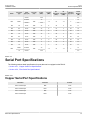
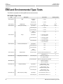
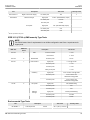
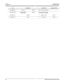
1
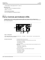
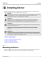
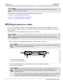
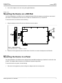
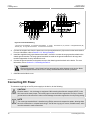
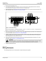
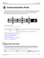
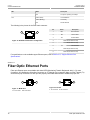
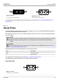
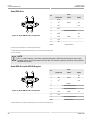
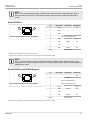
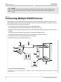
Preface
RUGGEDCOM RS416
Introduction
1
Installing Device
2
Communication Ports
3
Technical Specifications
4
Dimension Drawings
5
Certification
6
Installation Guide
6/2013
RC1018-EN-02
RUGGEDCOM RS416
Installation Guide
Copyright © 2014 Siemens Canada Ltd.
All rights reserved. Dissemination or reproduction of this document, or evaluation and communication of its contents, is not authorized
except where expressly permitted. Violations are liable for damages. All rights reserved, particularly for the purposes of patent application or
trademark registration.
This document contains proprietary information, which is protected by copyright. All rights are reserved. No part of this document may be
photocopied, reproduced or translated to another language without the prior written consent of Siemens Canada Ltd..
Disclaimer Of Liability
Siemens has verified the contents of this manual against the hardware and/or software described. However, deviations between the product
and the documentation may exist.
Siemens shall not be liable for any errors or omissions contained herein or for consequential damages in connection with the furnishing,
performance, or use of this material.
The information given in this document is reviewed regularly and any necessary corrections will be included in subsequent editions. We
appreciate any suggested improvements. We reserve the right to make technical improvements without notice.
Registered Trademarks
ROX™, Rugged Operating System On Linux™, CrossBow™ and eLAN™ are trademarks of Siemens Canada Ltd.. ROS® is a registered
trademark of Siemens Canada Ltd..
Other designations in this manual might be trademarks whose use by third parties for their own purposes would infringe the rights of the
owner.
Third Party Copyrights
Siemens recognizes the following third party copyrights:
• Copyright © 2004 GoAhead Software, Inc. All Rights Reserved.
Security Information
Siemens provides products and solutions with industrial security functions that support the secure operation of plants, machines, equipment
and/or networks. They are important components in a holistic industrial security concept. With this in mind, Siemens’ products and solutions
undergo continuous development. Siemens recommends strongly that you regularly check for product updates.
For the secure operation of Siemens products and solutions, it is necessary to take suitable preventive action (e.g. cell protection concept)
and integrate each component into a holistic, state-of-the-art industrial security concept. Third-party products that may be in use should also
be considered. For more information about industrial security, visit http://www.siemens.com/industrialsecurity.
To stay informed about product updates as they occur, sign up for a product-specific newsletter. For more information, visit http://
support.automation.siemens.com.
Warranty
Siemens warrants this product for a period of five (5) years from the date of purchase, conditional upon the return to factory for maintenance
during the warranty term. This product contains no user-serviceable parts. Attempted service by unauthorized personnel shall render all
warranties null and void. The warranties set forth in this article are exclusive and are in lieu of all other warranties, performance guarantees
and conditions whether written or oral, statutory, express or implied (including all warranties and conditions of merchantability and fitness for
a particular purpose, and all warranties and conditions arising from course of dealing or usage or trade). Correction of nonconformities in the
manner and for the period of time provided above shall constitute the Seller’s sole liability and the Customer’s exclusive remedy for defective
or nonconforming goods or services whether claims of the Customer are based in contract (including fundamental breach), in tort (including
negligence and strict liability) or otherwise.
For warranty details, visit www.siemens.com/ruggedcom or contact a Siemens customer service representative.
Contacting Siemens
ii
Address
Telephone
E-mail
Siemens Canada Ltd.
Industry Sector
300 Applewood Crescent
Concord, Ontario
Canada, L4K 5C7
Toll-free: 1 888 264 0006
Tel: +1 905 856 5288
Fax: +1 905 856 1995
[email protected]
Web
www.siemens.com/ruggedcom
RUGGEDCOM RS416
Installation Guide
Table of Contents
Table of Contents
Preface ................................................................................................................
v
Alerts .................................................................................................................................................. v
Related Documents ............................................................................................................................. v
Accessing Documentation .................................................................................................................... v
Training .............................................................................................................................................. vi
Customer Support .............................................................................................................................. vi
Chapter 1
Introduction ..........................................................................................................
1
1.1 Feature Highlights ........................................................................................................................ 1
1.2 Ports, Controls and Indicator LEDs ............................................................................................... 3
Chapter 2
Installing Device ..................................................................................................
5
2.1 Mounting the Device .................................................................................................................... 5
2.1.1 Mounting the Device to a Rack .......................................................................................... 6
2.1.2 Mounting the Device on a DIN Rail .................................................................................... 7
2.1.3 Mounting the Device to a Panel ......................................................................................... 7
2.2 Connecting Power ........................................................................................................................ 8
2.2.1 Connecting AC Power ....................................................................................................... 9
2.2.2 Connecting DC Power ..................................................................................................... 10
2.2.3 Wiring Examples ............................................................................................................. 11
2.3 Connecting the Failsafe Alarm Relay ........................................................................................... 14
2.4 Grounding the Device ................................................................................................................. 15
2.5 Connecting to the Device ........................................................................................................... 15
2.6 Cabling Recommendations ......................................................................................................... 16
Chapter 3
Communication Ports .........................................................................................
17
3.1 Copper Ethernet Ports ................................................................................................................ 17
3.2 Fiber Optic Ethernet Ports .......................................................................................................... 18
3.3 Serial Ports ................................................................................................................................ 19
3.4 Connecting Multiple RS485 Devices ............................................................................................ 22
3.5 Time Synchronization ................................................................................................................. 23
3.5.1 IRIG-B Ports ................................................................................................................... 23
iii
Table of Contents
RUGGEDCOM RS416
Installation Guide
3.5.2 IRIG-B Connection Considerations ................................................................................... 24
Chapter 4
Technical Specifications .....................................................................................
25
4.1 Power Supply Specifications ....................................................................................................... 25
4.2 Failsafe Relay Specifications ...................................................................................................... 25
4.3 Copper Ethernet Port Specifications ............................................................................................ 26
4.4 Fiber Optic Ethernet Port Specifications ....................................................................................... 26
4.4.1 10Base-FL Ethernet Optical Specifications ........................................................................ 26
4.4.2 Fast Ethernet (100 Mbps) Optical Specifications ................................................................ 26
4.5 Serial Port Specifications ............................................................................................................ 27
4.5.1 Copper Serial Port Specifications ..................................................................................... 27
4.5.2 Fiber Serial Port Specifications ......................................................................................... 28
4.6 IRIG-B Ports .............................................................................................................................. 28
4.7 Operating Environment ............................................................................................................... 28
4.8 Mechanical Specifications ........................................................................................................... 28
Chapter 5
Dimension Drawings ..........................................................................................
29
Chapter 6
Certification ........................................................................................................
33
6.1 Agency Approvals ...................................................................................................................... 33
6.2 FCC Compliance ........................................................................................................................ 33
6.3 Industry Canada Compliance ...................................................................................................... 33
6.4 EMI and Environmental Type Tests ............................................................................................. 34
iv
RUGGEDCOM RS416
Installation Guide
Preface
Preface
This guide describes the RUGGEDCOM RS416. It describes the major features of the device, installation,
commissioning and important technical specifications.
It is intended for use by network technical support personnel who are responsible for the installation,
commissioning and maintenance of the device. It is also recommended for use by network and system planners,
system programmers, and line technicians.
Alerts
The following types of alerts are used when necessary to highlight important information.
DANGER!
DANGER alerts describe imminently hazardous situations that, if not avoided, will result in death or
serious injury.
WARNING!
WARNING alerts describe hazardous situations that, if not avoided, may result in serious injury and/or
equipment damage.
CAUTION!
CAUTION alerts describe hazardous situations that, if not avoided, may result in equipment damage.
IMPORTANT!
IMPORTANT alerts provide important information that should be known before performing a procedure
or step, or using a feature.
NOTE
NOTE alerts provide additional information, such as facts, tips and details.
Related Documents
Other documents that may be of interest include:
• ROS User Guide for the RS416
Accessing Documentation
The latest Hardware Installation Guides and Software User Guides for most RUGGEDCOM products are
available online at www.siemens.com/ruggedcom.
Alerts
v
Preface
RUGGEDCOM RS416
Installation Guide
For any questions about the documentation or for assistance finding a specific document, contact a Siemens
sales representative.
Training
Siemens offers a wide range of educational services ranging from in-house training of standard courses on
networking, Ethernet switches and routers, to on-site customized courses tailored to the customer's needs,
experience and application.
Siemens' Educational Services team thrives on providing our customers with the essential practical skills to make
sure users have the right knowledge and expertise to understand the various technologies associated with critical
communications network infrastructure technologies.
Siemens' unique mix of IT/Telecommunications expertise combined with domain knowledge in the utility,
transportation and industrial markets, allows Siemens to provide training specific to the customer's application.
For more information about training services and course availability, visit www.siemens.com/ruggedcom or
contact a Siemens sales representative.
Customer Support
Customer support is available 24 hours, 7 days a week for all Siemens customers. For technical support or
general information, please contact Siemens Customer Support through any of the following methods:
• Online
Visit http://www.siemens.com/automation/support-request to submit a Support Request (SR) or check on the
status of an existing SR.
• Telephone
Call a local hotline center to submit a Support Request (SR). To locate a local hotline center, visit http://
www.automation.siemens.com/mcms/aspa-db/en/automation-technology/Pages/default.aspx.
• Mobile App
Install the Industry Online Support app by Siemens AG on any Android, Apple iOS or Windows mobile device
and be able to:
▪ Access Siemens's extensive library of support documentation, including FAQs, manuals, and much more
▪ Submit SRs or check on the status of an existing SR
▪ Find and contact a local contact person
▪ Ask questions or share knowledge with fellow Siemens customers and the support community via the forum
▪ And much more...
vi
Training
RUGGEDCOM RS416
Installation Guide
Chapter 1
Introduction
Introduction
The RUGGEDCOM RS416 is an industrially hardened serial device server with an integrated, fully managed,
Ethernet switch, designed to operate reliably in electrically harsh and climatically demanding environments.
Featuring a modular design that can support IEEE 1588 and IRIG-B time synchronization, up to 16 serial ports
and up to four Ethernet ports, the RS416 is able to interconnect and synchronize multiple types of intelligent
electronic devices (IEDs).
The time source is provided via IEEE 1588 v2 and converted to IRIG-B for distribution to the IEDs via the serial
ports or dedicated IRIG-B cabling. Each serial port supports standard data communications plus an IRIG-B timesynchronization output. Using the RS416 results in fewer connectivity devices reducing overall system costs and
extends the useful life of existing legacy IEDs minimizing capital expenditure for new equipment.
The RS416 provides a high level of immunity to electromagnetic interference and heavy electrical surges typical
of environments found in electric utility substations, factory floors or in curb side traffic control cabinets. The
RS416 meets or exceeds a wide range of industry standards including IEC 61850-3, IEEE 1613, IEC 61000-6-2
and IEC 61800-3. The RS416 also features a wide operating temperature range of -40 to 85 °C (-40 to 185 °F)
allowing it to be installed in virtually any location.
The embedded Rugged Operating System (ROS®) within the RS416 provides advanced layer 2 and layer 3
networking functions, advanced cyber security features, and a full array of intelligent functionality for high network
availability and manageability. Coupled with the ruggedized hardware design, the RS416 is ideal for creating
mission-critical, real-time, control applications in any harsh environment.
The following sections provide more information about the RS416:
• Section 1.1, “Feature Highlights”
• Section 1.2, “Ports, Controls and Indicator LEDs”
Section 1.1
Feature Highlights
Serial Device Server
• Modular design allows for 4, 8, 12, or 16 serial ports
• Fully compliant EIA RS422/TIA RS485, RS422, RS232 serial ports (software selectable) with IRIG-B outputs
• Serial fiber interface (ST)
• Transmit serial data over an IP network
• Support for Modbus TCP, DNP 3, TIN serial protocols
• Baud rates up to 230 kbps
• Raw socket mode allows conversion of any serial protocol
• Point-to-point and multi-point modes
• Converts Modbus RTU to Modbus
• Supports multiple Modbus masters
• Converts DNP3.0 to DNP over UDP/TCP
Feature Highlights
1
Chapter 1
Introduction
RUGGEDCOM RS416
Installation Guide
Ethernet Ports
• Integrated Ethernet switch
• Copper or fiber options
• Supports IEEE 1588 v2
• Non-blocking, store and forward switching
IRIG-B Option
• Conversion from IEEE 1588 v2
• One IRIG-B PWM/PPS Output
• One IRIG-B PWM Input
• Supports TTL levels (Format B002, B003)
• BNC Connectors
IEEE 1588
• Internal clock is synchronized with IEEE 1588 version 2
• 100μs time accuracy
Cyber Security Features
• Multi-level user passwords
• SSH/SSL (128-bit encryption)
• Enable/disable ports, MAC based port security
• Port based network access control (802.1x)
• VLAN (802.1Q) to segregate and secure network traffic
• RADIUS centralized password management
• SNMPv3 authentication and 56-bit encryption
Rated for Reliability in Harsh Environments
• Immunity to EMI and heavy electrical surges
• Meets IEEE 1613 (electric utility substations)
• Exceeds IEC 61850-3 (electric utility substations)
• Exceeds IEC 61800-3 (variable speed drive systems)
• Exceeds IEC 61000-6-2 (generic industrial)
• Exceeds NEMA TS-2 (traffic control equipment)
• Fully independent 2 kV (RMS) isolated serial ports
• -40 to 85 °C (-40 to 185 °F) operating temperature (no fans)
• 18 AWG galvanized steel enclosure
Universal Power Supply Options
• Fully integrated, dual-redundant (optional) power supplies
• Universal high-voltage range: 88-300 VDC or 85-264 VAC
• Popular low voltage ranges: 24 VDC (10-36 VDC), 48 VDC (36-59VDC)
• Terminal blocks for reliable maintenance free connections
2
Feature Highlights
RUGGEDCOM RS416
Chapter 1
Installation Guide
Introduction
• CSA/UL 60950-1 safety approved to 85 °C (185 °F)
Management Tools
• Web-based, Telnet, CLI management interfaces
• SNMP v1, v2 and v3
• Remote Monitoring (RMON)
• Rich set of diagnostics with logging and alarms
Section 1.2
Ports, Controls and Indicator LEDs
The RS416 features various ports, controls and indicator LEDs on the display panel for configuring and
troubleshooting the device. The display panel can be located on the rear, front or top of the device, depending on
the mounting configuration.
4
5
1
2
3
6
Figure 1: Display Panel
1. Port Status Indicator LEDs 2. Display Mode Indicator LEDs
LEDs 6. RS232 Serial Console Port (RJ45)
Port Status Indicator LEDs
3. Mode Button
4. Alarm Indicator LED
5. Power Module Indicator
These LEDs indicate the state of each port.
When Status mode is selected, these LEDs indicate when ports are active.
• Green (Solid) = Link detected
• Green (Blinking) = Link activity
• Off = No link detected
When Duplex mode is selected, these LEDs indicate when ports are operating in full or half
duplex mode.
• Green (Solid) = Full duplex mode
• Orange (Solid) = Half duplex mode
• Off = No link detected
When Speed mode is selected, these LEDs indicate the port speed.
•
•
•
•
Ports, Controls and Indicator LEDs
Green (Solid) = 1000 Mb/s
Green (Blinking) = 100 Mb/s
Orange (Solid) = 10 Mb/s
Off = No link detected
3
Chapter 1
RUGGEDCOM RS416
Introduction
Installation Guide
Display Mode Indicator LEDs
These LEDs indicate the current display mode for the port status indicator LEDs (i.e. Status,
Duplex or Speed).
Mode button
The Mode button sets the display mode for the port status indicator LEDs (i.e. Status,
Duplex or Speed). It can also be used to reset the device if held for 5 seconds.
Alarm Indicator LED
The alarm indicator LED illuminates when an alarm condition exists.
Power Module Indicator LEDs
These LEDs indicate the status of the power modules.
• Green = The power supply is supplying power
• Red = Power supply failure
• Off = No power supply is installed
RS232 Serial Console Port
4
This port is for interfacing directly with the device and accessing initial management
functions.
Ports, Controls and Indicator LEDs
RUGGEDCOM RS416
Installation Guide
Chapter 2
Installing Device
Installing Device
The following sections describe how to install the device, including mounting the device, installing/removing
modules, connecting power, and connecting the device to the network.
DANGER!
Electrocution hazard – risk of serious personal injury and/or damage to equipment. Before performing
any maintenance tasks, make sure all power to the device has been disconnected and wait
approximately two minutes for any remaining energy to dissipate.
WARNING!
Radiation hazard – risk of serious personal injury. This product contains a laser system and is
classified as a CLASS 1 LASER PRODUCT. Use of controls or adjustments or performance of
procedures other than those specified herein may result in hazardous radiation exposure.
IMPORTANT!
This product contains no user-serviceable parts. Attempted service by unauthorized personnel shall
render all warranties null and void.
Changes or modifications not expressly approved by Siemens Canada Ltd. could invalidate
specifications, test results, and agency approvals, and void the user's authority to operate the
equipment.
IMPORTANT!
This product should be installed in a restricted access location where access can only be gained by
authorized personnel who have been informed of the restrictions and any precautions that must be
taken. Access must only be possible through the use of a tool, lock and key, or other means of security,
and controlled by the authority responsible for the location.
• Section 2.1, “Mounting the Device”
• Section 2.2, “Connecting Power”
• Section 2.3, “Connecting the Failsafe Alarm Relay”
• Section 2.4, “Grounding the Device”
• Section 2.5, “Connecting to the Device”
• Section 2.6, “Cabling Recommendations”
Section 2.1
Mounting the Device
The RS416 is designed for maximum mounting and display flexibility. It can be equipped with connectors that
allow it to be installed in a 48 cm (19 in) rack, 35 mm (1.4 in) DIN rail, or directly on a panel.
Mounting the Device
5
Chapter 2
RUGGEDCOM RS416
Installing Device
Installation Guide
NOTE
For detailed dimensions of the device with either rack, DIN rail or panel hardware installed, refer to
Chapter 5, Dimension Drawings.
The following sections describe the various methods of mounting the device:
• Section 2.1.1, “Mounting the Device to a Rack”
• Section 2.1.2, “Mounting the Device on a DIN Rail”
• Section 2.1.3, “Mounting the Device to a Panel”
Section 2.1.1
Mounting the Device to a Rack
For rack mount installations, the RS416 can be equipped with rack mount adapters pre-installed at the front or
rear of the chassis. Additional adapters are provided to further secure the device in high-vibration or seismically
active locations.
To secure the device to a standard 48 cm (19 in) rack, do the following:
NOTE
The device can be ordered with the communication ports located at the front or rear of the device.
Placing the ports at the rear allows all data and power cabling to be installed and connected at the rear
of the rack.
1.
Make sure the rack mount adapters are installed on the correct side of the chassis.
NOTE
The chassis features multiple mounting holes, allowing the rack mount adapters to be installed up
to 25 mm (1 in) from the face of the device.
1
2
3
3
Figure 2: Rack Mount Adaptors
1. Rear
2. Front
3. Rack Mount Adaptor
2.
If required, install adapters on the opposite side of the device to protect from vibrations.
3.
Insert the device into the rack.
NOTE
Since heat within the device is channelled to the enclosure, it is recommended that 1 rack-unit
of space, or 44 mm (1.75 in), be kept empty above the device. This allows a small amount of
convectional airflow.
Forced airflow is not required. However, any increase in airflow will result in a reduction of ambient
temperature and improve the long-term reliability of all equipment mounted in the rack space.
6
Mounting the Device to a Rack
RUGGEDCOM RS416
Chapter 2
Installation Guide
4.
Installing Device
Secure the adapters to the rack using the supplied hardware.
Section 2.1.2
Mounting the Device on a DIN Rail
For DIN rail installations, the RS416 can be equipped with panel/DIN rail adapters pre-installed on each side of
the chassis. The adapters allow the device to be slid onto a standard 35 mm (1.4 in) DIN rail.
To mount the device to a DIN rail, do the following:
1.
Align the adapters with the DIN rails and slide the device into place.
1
3
2
2
3
Figure 3: DIN Rail Mounting
1. Panel/DIN Rail Adaptor
2.
2. DIN Rail
3. Screw
Install one of the supplied screws on either side of the device to secure the adapters to the DIN rails.
Section 2.1.3
Mounting the Device to a Panel
For panel installations, the RS416 can be equipped with panel/DIN rail adapters pre-installed on each side of the
chassis. The adapters allow the device to be attached to a panel using screws.
To mount the device to a panel, do the following:
1.
Place the device against the panel and align the adapters with the mounting holes.
Mounting the Device on a DIN Rail
7
Chapter 2
RUGGEDCOM RS416
Installing Device
Installation Guide
1
1
2
Figure 4: Panel Mounting
1. Screw
2.
2. Panel/DIN Rail Adaptor
Install the supplied screws to secure the adapters to the panel.
Section 2.2
Connecting Power
The RS416 supports single or dual redundant high AC and/or low DC power supplies. The use of two power
modules is recommended to provide redundancy and load balancing.
The RS416 can be equipped with either a screw-type or pluggable terminal block, which provides power to both
power supplies. The screw-type terminal block is installed using Phillips screws and compression plates, allowing
either bare wire connections or crimped terminal lugs. Use #6 size ring lugs for secure, reliable connections
under severe shock or vibration.
NOTE
• For maximum redundancy in a dual power supply configuration, use two independent power
sources.
• For 100-240 VAC rated equipment, an appropriately rated AC circuit breaker must be installed.
• For 88-300 VDC rated equipment, an appropriately rated DC circuit breaker must be installed.
• Use only #16 gage copper wiring when connecting terminal blocks.
• A circuit breaker is not required for 12, 24 or 48 VDC rated power supplies.
8
Connecting Power
RUGGEDCOM RS416
Installation Guide
Chapter 2
Installing Device
• It is recommended to provide a separate circuit breaker for each power supply module.
• Equipment must be installed according to applicable local wiring codes and standards.
The following sections describe how to connect power to the device:
• Section 2.2.1, “Connecting AC Power”
• Section 2.2.2, “Connecting DC Power”
• Section 2.2.3, “Wiring Examples”
Section 2.2.1
Connecting AC Power
To connect a high AC power supply to the device, do the following:
CAUTION!
Electrical hazard – risk of damage to equipment. Do not connect AC power cables to a DC power
supply terminal block. Damage to the power supply may occur.
CAUTION!
Electrical hazard – risk of damage to equipment. Before testing the dielectric strength (HIPOT) in the
field, remove the metal jumper. This metal jumper connects transient suppression circuitry to chassis
ground and must be removed in order to avoid damage to transient suppression circuitry during testing.
NOTE
The terminal block is divided into separate terminals for each internal power supply. Make sure to
connect the external power supply to the appropriate terminals.
1.
Remove the terminal block cover.
2.
If a screw-type terminal block is installed, remove the screws from the appropriate terminals. Use these
screws along with #6 ring lugs to secure the wires to the terminal block.
3.
Connect the positive wire from the power source to the positive/live (+/L) terminal on the terminal block. For
more information, refer to Section 2.2.3, “Wiring Examples”.
Connecting AC Power
9
Chapter 2
RUGGEDCOM RS416
Installing Device
Installation Guide
6
4
7
5
6
4
5
1
2
3
4
5
6
4
7
5
3
6
Figure 5: Terminal Block Wiring
1. Screw-Type Terminal Block 2. Pluggable Terminal Block 3. Jumper
Terminal (-/N) 6. Surge Ground Terminal 7. Chassis Ground Terminal
4. Positive/Live (+/L) Terminal
5. Negative/Neutral (-/N)
4.
Connect the negative wire from the power source to the negative/neutral (-/N) terminal on the terminal block.
For more information, refer to Section 2.2.3, “Wiring Examples”.
5.
Install the supplied metal jumper between terminals 2, 4 and 6 to connect the surge ground terminals to the
chassis ground terminal. The surge ground terminals are used as the ground conductor for all surge and
transient suppression circuitry internal to the unit.
6.
Connect the ground terminal on the power source to the chassis ground terminal on the device. For more
information, refer to Section 2.4, “Grounding the Device”
DANGER!
Electrocution hazard – risk of death, serious personal injury and/or damage to the device. Make
sure the supplied terminal block cover is always installed before the device is powered.
7.
Install the terminal block cover.
Section 2.2.2
Connecting DC Power
To connect a single high or low DC power supply to the device, do the following:
CAUTION!
Electrical hazard – risk of damage to equipment. Before testing the dielectric strength (HIPOT) in the
field, remove the metal jumper. This metal jumper connects transient suppression circuitry to chassis
ground and must be removed in order to avoid damage to transient suppression circuitry during testing.
NOTE
The screw-type terminal block is installed using Philips screws and compression plates, allowing either
bare wire connections or crimped terminal lugs. Use #6 size ring lugs for secure, reliable screws, which
must be removed to make connections.
10
Connecting DC Power
RUGGEDCOM RS416
Chapter 2
Installation Guide
Installing Device
1.
Remove the terminal block cover.
2.
If a screw-type terminal block is installed, remove the screws from the appropriate terminals. Use these
screws along with #6 ring lugs to secure the wires to the terminal block.
3.
Connect the positive wire from the power source to the positive/live (+/L) terminal on the terminal block. For
more information, refer to Section 2.2.3, “Wiring Examples”.
6
4
7
5
6
4
5
1
2
3
4
5
6
4
7
5
3
6
Figure 6: Terminal Block Wiring
1. Screw-Type Terminal Block 2. Pluggable Terminal Block 3. Jumper
Terminal 6. Surge Ground Terminal 7. Chassis Ground Terminal
4. Positive/Live (+/L) Terminal
5. Negative/Neutral (-/N)
4.
Connect the negative wire from the power source to the negative/neutral (-/N) terminal on the terminal block.
For more information, refer to Section 2.2.3, “Wiring Examples”.
5.
Install the supplied metal jumper between terminals 2, 4 and 6 to connect the surge ground terminals to the
chassis ground terminal. The surge ground terminals are used as the ground conductor for all surge and
transient suppression circuitry internal to the unit.
6.
Connect the ground terminal on the power source to the chassis ground terminal on the device. For more
information, refer to Section 2.4, “Grounding the Device”
DANGER!
Electrocution hazard – risk of death, serious personal injury and/or damage to the device. Make
sure the supplied terminal block cover is always installed before the device is powered.
7.
Install the terminal block cover.
Section 2.2.3
Wiring Examples
The following illustrate how to connect power to single and dual power supplies.
Wiring Examples
11
Chapter 2
Installing Device
RUGGEDCOM RS416
Installation Guide
Figure 7: Single AC Power Supply
Figure 8: Single DC Power Supply
12
Wiring Examples
RUGGEDCOM RS416
Installation Guide
Chapter 2
Installing Device
Figure 9: Dual AC Power Supply
Figure 10: Dual DC Power Supply
Wiring Examples
13
Chapter 2
RUGGEDCOM RS416
Installing Device
Installation Guide
Figure 11: Dual AC/DC Power Supply
Section 2.3
Connecting the Failsafe Alarm Relay
The failsafe relay can be configured to latch based on alarm conditions. The NO (Normally Open) contact is
closed when the unit is powered and there are no active alarms. If the device is not powered or if an active alarm
is configured, the relay opens the NO contact and closes the NC (Normally Closed) contact.
NOTE
Control of the failsafe relay output is configurable through ROS. One common application for this relay
is to signal an alarm if a power failure occurs. For more information, refer to the ROS User Guide for
the RS416.
The following shows the proper relay connections.
14
Connecting the Failsafe Alarm Relay
RUGGEDCOM RS416
Chapter 2
Installation Guide
Installing Device
3
5
3
5
1
2
4
4
Figure 12: Failsafe Alarm Relay Wiring
1. Screw-Type Terminal Block
Terminal
2. Pluggable Terminal Block
3. Normally Open Terminal
4. Common Terminal
5. Normally Closed
Section 2.4
Grounding the Device
The RS416 chassis ground terminal uses a #6-32 screw. It is recommended to terminate the ground connection
with a #6 ring lug and torque it to 1.7 N·m (15 lbf·in).
2
3
1
Figure 13: Chassis Ground Connection
1. Stainless Steel Stud
2. #6-32 Screw
3. #6 Ring Lug
Section 2.5
Connecting to the Device
The following describes the various methods for accessing the ROS console and Web interfaces on the device.
For more detailed instructions, refer to the ROS User Guide for the RS416.
Grounding the Device
15
Chapter 2
RUGGEDCOM RS416
Installing Device
Installation Guide
RS232 Console Port
Connect a PC or terminal directly to the RS232 console port to access the boot-time control and ROS interfaces.
The console port provides access to ROS's console and Web interfaces.
IMPORTANT!
The console port is intended to be used only as a temporary connection during initial configuration or
troubleshooting.
Connection to the console port is made using an RJ45-to-DB9 console cable. The following is the pin-out for the
console port:
Pin
8
1
1
6
2
1
3
4
DTR
Data Terminal Ready
4
5
GND
Signal Ground
5
2
RxD
Receive Data (to DTE)
6
3
TxD
Transmit Data
(from DTE)
7
8
CTS
8
7
RTS
9
c
1
The DSR, DCD and DTR pins are connected together internally.
b
The CTS and RTS pins are connected together internally.
c
RI is not connected.
Description
DB9
Female
Figure 14: RJ45 Console Port Pin Configuration
a
Name
RJ45 Male
DSR
a
Data Set Ready
Reserved (Do Not Connect)
a
RI
b
Clear to Send
b
Read to Send
Ring Indicator
Communication Ports
Connect any of the available Ethernet ports on the device to a management switch and access the ROS console
and Web interfaces via the device's IP address. For more information about available ports, refer to Chapter 3,
Communication Ports.
Section 2.6
Cabling Recommendations
Siemens does not recommend the use of copper cabling of any length for critical, real-time substation automation
applications. All copper Ethernet ports on RUGGEDCOM products include transient suppression circuitry
to protect against damage from electrical transients and conform with IEC 61850-3 and IEEE 1613 Class 1
standards. This means that during a transient electrical event, communications errors or interruptions may occur,
but recovery is automatic.
Siemens also does not recommend using copper Ethernet ports to interface with devices in the field across
distances that could produce high levels of ground potential rise (i.e. greater than 2500 V), during line-to-ground
fault conditions.
16
Cabling Recommendations
RUGGEDCOM RS416
Chapter 3
Installation Guide
Communication Ports
Communication Ports
The RS416 can be equipped with various types of communication ports to enhance its abilities and performance.
To determine which ports are equipped on the device, refer to the factory data file available through ROS. For
more information on how to access the factory data file, refer to the ROS User Guide for the RS416.
Each communication port type has a specific place in the RS416 chassis.
1
3
5
2
4
6
Figure 15: Port Assignment
1. Slot 1
2. Slot 2
3. Slot 3
4. Slot 4
5. Slot 5
Slot
6. Slot 6
Type
1 to 4
Serial Ports
5 to 6
Fast Ethernet (10/100Base-TX, 10Base-FL or 10/100Base-FX) or IRIG-B Ports
The following sections describe the available ports:
• Section 3.1, “Copper Ethernet Ports”
• Section 3.2, “Fiber Optic Ethernet Ports”
• Section 3.3, “Serial Ports”
• Section 3.4, “Connecting Multiple RS485 Devices”
• Section 3.5, “Time Synchronization”
Section 3.1
Copper Ethernet Ports
The RS416 supports several 10/100Base-TX Ethernet ports that allow connection to standard Category 5
(CAT-5) unshielded twisted-pair (UTP) cables with RJ45 male connectors. The RJ45 connectors are directly
connected to the chassis ground on the device and can accept CAT-5 shielded twisted-pair (STP) cables.
Each port features a Speed and Link LED that indicates the state of the port.
LED
State
Description
Speed
Yellow
The port is operating at 100 Mbps
Copper Ethernet Ports
17
Chapter 3
RUGGEDCOM RS416
Communication Ports
Installation Guide
LED
Link
State
Description
Off
The port is operating at 10 Mbps
Yellow (Solid)
Link established
Yellow (Blinking)
Link activity
Off
No link detected
The following is the pin-out for the RJ45 male connector:
8
1
Figure 16: RJ45 Ethernet Port Pin Configuration
Pin
Name
Description
1
RX+
Receive Data+
2
RX-
Receive Data-
3
TX+
Transmit Data+
4
Reserved (Do Not Connect)
5
Reserved (Do Not Connect)
6
TX-
Transmit Data-
7
Reserved (Do Not Connect)
8
Reserved (Do Not Connect)
For specifications on the available copper Ethernet ports, refer to Section 4.3, “Copper Ethernet Port
Specifications”.
Section 3.2
Fiber Optic Ethernet Ports
Fiber optic Ethernet ports are available with either MTRJ (Mechanical Transfer Registered Jack), LC (Lucent
Connector), SC (Standard or Subscriber Connector) or ST (Straight Tip) connectors. Make sure the Transmit (Tx)
and Receive (Rx) connections of each port are properly connected and matched to establish a proper link.
1
Figure 17: MTRJ Port
1. Tx Connector
18
2. Rx Connector
1
2
2
Figure 18: LC Port
1. Tx Connector
2. Rx Connector
Fiber Optic Ethernet Ports
RUGGEDCOM RS416
Chapter 3
Installation Guide
Communication Ports
1
2
Figure 19: SC Port
1. Tx Connector
1
2
Figure 20: ST Port
2. Rx Connector
1. Tx Connector
2. Rx Connector
For specifications on the available fiber optic Ethernet ports, refer to Section 4.4, “Fiber Optic Ethernet Port
Specifications”.
Section 3.3
Serial Ports
The RS416 supports serial cards with fiber serial ST (Straight Tip) connectors, RS232/RS485/RS422 DB9 serial
ports or RS232/RS485/RS422 RJ45 serial ports.
Serial DB9 and RJ45 ports can be run in RS232, RS485 or RS422 mode. They can also be ordered with IRIG-B
time code support.
NOTE
On power-up, all serial RJ45 ports default to RS485 mode. Each port can be individually set to RS232,
RS485 or RS422 mode through ROS. For more information, refer to the ROS User Guide for the
RS416.
NOTE
For information about how to connect devices configured to run in RS485 mode, refer to Section 3.4,
“Connecting Multiple RS485 Devices”.
All serial ports feature an LED that indicates the current state of the port.
State
Description
Green
Link activity detected
Off
No link detected
For specifications on serial ports, refer to Section 4.5, “Serial Port Specifications”.
The following is the pin-out description for ST, DB9 and RJ45 serial ports:
Fiber Serial Port
1
2
Figure 21: ST Port
1. Tx Connector
Serial Ports
2. Rx Connector
19
Chapter 3
RUGGEDCOM RS416
Communication Ports
Installation Guide
Serial DB9 Port
5
1
Pin
6
RS232 DCE
1
DCD
2
TX
3
RX
4
9
Mode
b
RX+
DTR
Common (Isolated) Ground
a
7
RTS
8
CTS
9
RI
RXTX/RX-
In RS232 DCE mode, ports transmit to DTE devices on pin 2 and receive from DTE on pin 3.
c
RI is not connected.
TX-
c
Shield
The DSR, DCD and DTR pins are connected together internally.
TX+
a
DSR
b
TX/RX+
b
6
a
RS422
a
5
Figure 22: Serial DB9 Port Pin Configuration
RS485
Chassis Ground
NOTE
Pins 1, 4 and 6 and pins 7 and 8 are connected internally. In RS232 mode, these pins enter a high
impedance state. A DTE that asserts RTS will see CTS asserted. However, the device will not perform
hardware flow control.
Serial DB9 Port with IRIG-B Support
5
1
Pin
Mode
RS232 DTE
RS485
1
9
6
Figure 23: Serial DB9 Port Pin Configuration
d
20
RS422
RX-
2
RX
3
TX
d
TX/RX+
d
RX+
4
IRIG-B+
5
Common (Isolated) Ground
6
Common (Isolated) Ground
7
RTS
8
CTS
TX+
TX/RX-
9
Common (Isolated) Ground
Shield
Chassis Ground
TX-
In RS232 DTE mode, ports transmit to DTE devices on pin 2 and receive from DTE on pin 3.
Serial Ports
RUGGEDCOM RS416
Chapter 3
Installation Guide
Communication Ports
NOTE
Pins 7 and 8 are connected internally. In RS232 mode, these pins enter a high impedance state. A
DTE that asserts RTS will see CTS asserted. However, the device will not perform hardware flow
control.
Serial RJ45 Port
Pin
8
1
Figure 24: Serial RJ45 Port Pin Configuration
RS232 Mode
1
DSR
2
DCD
3
DTR
RX-
e
Common (Isolated) Ground
f
5
RXD
6
TXD
7
CTS
8
RTS
RX+
f
Shield
The DSR, DCD and DTR pins are connected together internally.
f
In RS232 mode, the RJ45 ports conform to EIA-561 DTE, which transmit on TXD and receive on RXD.
RS422 Mode
e
4
e
RS485 Mode
e
TX/RX+
TX+
TX/RX-
TX-
Chassis Ground
NOTE
Pins 1, 2 and 3 and pins 7 and 8 are connected internally. In RS232 mode, these pins enter a high
impedance state. A DTE that asserts RTS will see CTS asserted. However, the device will not perform
hardware flow control.
Serial RJ45 Port with IRIG-B Support
Pin
8
1
Figure 25: Serial RJ45 Port Pin Configuration
RS485 Mode
RS422 Mode
1
RX-
2
+IRIG-B
3
Common (Isolated) Ground
4
Common (Isolated) Ground
g
5
RXD
6
TXD
7
CTS
8
RTS
Shield
g
RS232 Mode
g
RX+
TX/RX+
TX+
TX/RX-
TX-
Chassis Ground
In RS232 mode, the RJ45 ports conform to EIA-561 DTE, which transmit on TXD and receive on RXD.
Serial Ports
21
Chapter 3
RUGGEDCOM RS416
Communication Ports
Installation Guide
NOTE
Pins 7 and 8 are connected internally. In RS232 mode, these pins enter a high impedance state. A
DTE that asserts RTS will see CTS asserted. However, the device will not perform hardware flow
control.
Section 3.4
Connecting Multiple RS485 Devices
Each RS485 port can communicate with multiple RS485 devices by wiring devices together in sequence over a
single twisted pair with transmit and receive signals on the same two wires (half duplex). For reliable, continuous
communication, adhere to the following guidelines:
• To minimize the effects of ambient electrical noise, use shielded cabling.
• The correct polarity must be observed throughout a single sequence or ring.
• The number of devices wired should not exceed 32, and total distance should be less than 1219 m (4000 ft) at
100 kbps.
• The Common terminals should be connected to the common wire inside the shield.
• The shield should be connected to earth ground at a single point to avoid loop currents.
• The twisted pair should be terminated at each end of the chain.
The following shows the recommended RS485 wiring.
3
5
< 1219 m (4000 in)
2
4
1
5
120Ω 10nF
6
120Ω 10nF
Figure 26: Recommended RS485 Wiring
1. RS416 Device 2. Common (Isolated Ground)
Devices (32 Total)
22
3. Negative
4. Positive
5. Shield to Earth (Connected At a Single Point)
6. RS485
Connecting Multiple RS485 Devices
RUGGEDCOM RS416
Chapter 3
Installation Guide
Communication Ports
Section 3.5
Time Synchronization
The RS416 is able to derive and provide time synchronization via Ethernet using the Precision Time Protocol
(PTP) and NTP (Network Time Protocol). With the IRIG-B module is installed, the RS416 is also able to
synchronize to received IRIG-B time signal and to distribute it via BNC and via serial ports equipped with IRIG-B
signals. Please refer to the data sheet for ordering options.
The following are the time synchronization sources supported by the RS416 for time synchronization.
Synchronization Source
Without IRIG Module
With IRIG Module
NTP
Yes
Yes
IEEE 1588 v2
Yes
Yes
IRIG-B PWM
No
Yes
The following are the time synchronization services supported by the RS416.
Synchronization Service
Without IRIG Module
With IRIG Module
NTP
Yes
Yes
IEEE 1588 v2
Yes
Yes
IRIG-B PWM
No
Yes
NTP (Network Time Protocol) is the standard for synchronizing the clocks of computer systems throughout the
Internet and is suitable for systems that require accuracies on the order of 1 ms.
IRIG-B (Inter Range Instrumentation Group, mod B) time synchronization is an established, inter-device time
synchronization mechanism which provides accuracy on the order of 1ms to 1μs.
IEEE 1588 is designed to fill a niche not well served by either NTP or IRIG-B. IEEE1588 is designed for local
systems requiring accuracies on the order of 100 nanoseconds. IEEE 1588 is also designed for applications that
cannot bear the cost of a GPS receiver at each node or for which GPS signals are inaccessible. Every Ethernet
port on the RS416 supports IEEE1588.
Section 3.5.1
IRIG-B Ports
The IRIG-B output ports described in sections 3.3 and 3.5 derive their time from the IRIG-B module, which
occupies one slot in lieu of a two-port Ethernet module. The IRIGB module has one dedicated input and one
dedicated output. These ports operate in IRIG-B PWM mode (IRIG-B006 or IRIG-B007) only.
The following figure shows the layout of the BNC connectors on the IRIG-B I/O board. The LED in the center
of the board, indicated by the mark, reflects the status of the received IRIG-B signal, and is described in the
following table.
Time Synchronization
23
Chapter 3
RUGGEDCOM RS416
Installation Guide
TTLIN
TTLOUT
Communication Ports
Figure 27: IRIG-B Daughter Board BNC Connections
LED Color
Meaning
Off
No IRIG-B signal detected
Red
Errors detected in received IRIG-B signal
Green
Received IRIG-B signal is good
Section 3.5.2
IRIG-B Connection Considerations
The number of IRIG-B devices that can be connected to a given IRIG-B output is dependent on the cabling
type and length, as well as the input impedances of connected devices. The following shows a simplified circuit
diagram of the interface between an IRIG-B output and connected devices.
1
2
3
Figure 28: IRIG-B Simplified Schematic
1. Source
2. Cabling
3. Device
The maximum number of devices (N) that can be connected to the source is determined by verifying that the
source current (IS) required to drive the connected devices is less than the maximum drive current the output can
provide, and that the load voltage (VL) seen by the connected devices is greater than their minimum required
voltage. For IRIG-B port specifications, refer to Section 4.6, “IRIG-B Ports”.
24
IRIG-B Connection Considerations
RUGGEDCOM RS416
Chapter 4
Installation Guide
Technical Specifications
Technical Specifications
The following sections provide important technical specifications related to the device and available modules:
• Section 4.1, “Power Supply Specifications”
• Section 4.2, “Failsafe Relay Specifications”
• Section 4.3, “Copper Ethernet Port Specifications”
• Section 4.4, “Fiber Optic Ethernet Port Specifications”
• Section 4.5, “Serial Port Specifications”
• Section 4.6, “IRIG-B Ports”
• Section 4.7, “Operating Environment”
• Section 4.8, “Mechanical Specifications”
Section 4.1
Power Supply Specifications
Power Supply Type
Input Range
Internal Fuse
ab
Rating
Minimum
Maximum
10 VDC
36 VDC
6.3 A(F)
36 VDC
59 VDC
3.15 A(T)
d
88 VDC
300 VDC
d
85 VAC
264 VAC
12 VDC
24 VDC
48 VDC
HI (125/250 VDC)
HI (110/230 VAC)
2 A(T)
Isolation
Maximum Power
c
Consumption
1.5 kVDC
25 W
4 kVAC, 5.5 kVDC
a
(F) denotes fast-acting fuse
b
(T) denotes time-delay fuse.
c
Power consumption varies based on configuration. 10/100Base-TX ports consume roughly 1 W less than fiber optic ports.
d
The HI power supply is the same power supply for both AC and DC.
Section 4.2
Failsafe Relay Specifications
Maximum Switching Voltage
Rated Switching Current
30 VAC
0.3 A, 1.0 A
80 VDC
0.3
Power Supply Specifications
25
Chapter 4
RUGGEDCOM RS416
Technical Specifications
Installation Guide
Section 4.3
Copper Ethernet Port Specifications
The following details the specifications for copper Ethernet ports that can be ordered with the RS416.
Speed
e
10/100Base-TX
e
Connector
Duplex
Cable Type
RJ45
FDX/HDX
> CAT-5
e
Auto-negotiating.
f
Shielded or unshielded.
g
Auto-crossover and auto-polarity.
h
Typical distance. Dependent on the number of connectors and splices.
i
RMS 1 minute.
f
Wiring
g
Standard
Maximum
h
Distance
Isolation
TIA/EIA
T568A/B
100 m
(328 ft)
1.5 kV
i
Section 4.4
Fiber Optic Ethernet Port Specifications
The following sections detail fiber optic specifications for ports that can be equipped on the RS416..
• Section 4.4.1, “10Base-FL Ethernet Optical Specifications”
• Section 4.4.2, “Fast Ethernet (100 Mbps) Optical Specifications”
Section 4.4.1
10Base-FL Ethernet Optical Specifications
Mode
Connector
Type
MM
ST
Cable
Type (µm)
62.5/125
50/125
Tx λ (typ.)
(nm)
850
Tx min
(dBm)
Tx max
(dBm)
-16
-9
-19.8
-12.8
Rx
Sensitivity
(dBm)
Rx
Saturation
(dBm)
Distance
(typ.) (km)
-34
-11.2
2
Power
Budget
(dB)
18
14.2
Section 4.4.2
Fast Ethernet (100 Mbps) Optical Specifications
26
Mode
Connector
Type
MM
ST
MM
SC
Cable
Type (μm)
62.5/125
50/125
62.5/125
Tx λ (typ.)
(nm)
1300
1300
Tx min.
(dBm)
-19
-22.5
-19
Tx max.
(dBm)
Rx
Sensitivity
(dBm)
Rx
Saturation
(dBm)
Distance
(typ.) (km)
-14
-31
-14
2
-14
-31
-14
2
Power
Budget
(dB)
12
8.5
12
Copper Ethernet Port Specifications
RUGGEDCOM RS416
Chapter 4
Installation Guide
Mode
Technical Specifications
Connector
Type
Cable
Type (μm)
Tx λ (typ.)
(nm)
50/125
62.5/125
Tx min.
(dBm)
Tx max.
(dBm)
Rx
Sensitivity
(dBm)
Rx
Saturation
(dBm)
Distance
(typ.) (km)
-22.5
MM
MTRJ
SM
ST
9/125
1300
SM
SC
9/125
SM
LC
SM
8.5
-19
12
-14
-31
-14
2
-15
-8
-32
-3
20
17
1300
-15
-8
-31
-7
20
16
9/125
1300
-15
-8
-34
-7
20
19
LC
9/125
1300
-15
-8
-34
-7
20
19
SM
SC
9/125
1300
-5
0
-34
-3
50
29
SM
LC
9/125
1300
-5
0
-35
3
50
30
SM
SC
9/125
1300
0
5
-37
0
90
37
SM
LC
9/125
1300
0
5
-37
0
90
37
MTRJ
62.5/125
LC
50/125
-14
-31
-14
2
MM
50/125
1300
Power
Budget
(dB)
1300
-22.5
-19
-22.5
8.5
12
8.5
Section 4.5
Serial Port Specifications
The following sections detail specifications for ports that can be equipped on the RS416.
• Section 4.5.1, “Copper Serial Port Specifications”
• Section 4.5.2, “Fiber Serial Port Specifications”
Section 4.5.1
Copper Serial Port Specifications
Baud Rate
Connector
Isolation
1200 to 230400 kbps
DB9
2.5 kV
1200 to 230400 kbps
RJ45
2.5 kV
1200 to 230400 kbps
DB9
2.5 kV
1200 to 230400 kbps
RJ45
2.5 kV
Serial Port Specifications
27
Chapter 4
RUGGEDCOM RS416
Technical Specifications
Installation Guide
Section 4.5.2
Fiber Serial Port Specifications
Mode
Connector
Typical Distance (km)
Optical
Wavelength (nm)
Multimode
ST
5
850
Cable Size
50/125
62.5/125
Section 4.6
IRIG-B Ports
Table: IRIG-B PWM Input
Parameter
Typical Value
Input Voltage
TTL-Compatible
Input Impedance
> 200 kΩ
Table: IRIG-B Port Output Specifications
Parameter
Typical Value
Output Current (IS)
100 mA
Section 4.7
Operating Environment
Parameter
Range
Ambient Operating Temperature
-40 to 85 °C
(-40 to 185 °F)
Ambient Relative Humidity
5% to 95%
Ambient Storage Temperature
-40 to 85 °C
(-40 to 185 °F)
Comments
Measured from a 30 cm (12 in) radius surrounding the center of the
enclosure.
Non-condensing
Section 4.8
Mechanical Specifications
28
Parameter
Value
Dimensions
Refer to Chapter 5, Dimension Drawings
Weight
4.5 kg (10 lbs)
Ingress Protection
IP40 (1 mm or 0.04 in objects)
Enclosure
18 AWG Galvanized Steel
Fiber Serial Port Specifications
RUGGEDCOM RS416
Chapter 5
Installation Guide
Dimension Drawings
Dimension Drawings
NOTE
All dimensions are in millimeters, unless otherwise stated.
303.28
44.45
285.24
438.15
Figure 29: Overall Dimensions
29
Chapter 5
RUGGEDCOM RS416
Installation Guide
31.75
Figure 30: Rack Mount Dimensions
30
4.57
25.40
28.96
479.30
461.01
6.35
6.35
12.70
308.10
314.71
50.80
Dimension Drawings
11.68
21.08
32.64
RUGGEDCOM RS416
Chapter 5
Dimension Drawings
486.4
476.3
3
2
1
8
12
16
20
24
28
32
4
MODE
CONSOLE
57600-N-8-1
DUPLEX
SPEED
STATUS
POWER1
POWER2
ALARM
84.1
134.3
285.5
159.8
158.0
125.5
80.0
6
10
5
9
127.5
7
11
15
19
23
27
31
13 14
17 18
21 22
25 26
29 30
10.4
7.4
38.9
51.6
Installation Guide
11.7
Figure 31: Panel and DIN Rail Mount Dimensions
31
RUGGEDCOM RS416
Installation Guide
Chapter 5
Dimension Drawings
32
RUGGEDCOM RS416
Chapter 6
Installation Guide
Certification
Certification
The RS416 device has been thoroughly tested to guarantee its conformance with recognized standards and has
received approval from recognized regulatory agencies.
• Section 6.1, “Agency Approvals”
• Section 6.2, “FCC Compliance”
• Section 6.3, “Industry Canada Compliance”
• Section 6.4, “EMI and Environmental Type Tests”
Section 6.1
Agency Approvals
Agency
Standards
Comments
CSA
CSA C22.2 No. 60950-1, UL 60950-1
Approved
CE
EN 60950-1, EN 61000-6-2, EN
55022, EN 50581, EN 60825-1
Approved
FCC
FCC Part 15, Class A
Approved
FDA/CDRH
21 CFR Chapter I, Sub-chapter J
Compliant
Section 6.2
FCC Compliance
This equipment has been tested and found to comply with the limits for a Class A digital device pursuant to Part
15 of the FCC Rules. These limits are designed to provide reasonable protection against harmful interference
when the equipment is operated in a commercial environment.
This equipment generates, uses and can radiate radio frequency energy and, if not installed and used in
accordance with the instruction manual, may cause harmful interference to radio communications. Operation of
this equipment in a residential area is likely to cause harmful interference in which case the user will be required
to correct the interference on his own expense.
Section 6.3
Industry Canada Compliance
CAN ICES-3 (A) / NMB-3 (A)
Agency Approvals
33
Chapter 6
RUGGEDCOM RS416
Certification
Installation Guide
Section 6.4
EMI and Environmental Type Tests
The RS416 has passed the following EMI and environmental tests.
IEC 61850-3 Type Tests
Test
IEC 61000-4-2
Description
ESD
Test Levels
Severity Levels
Enclosure
Contact
+/- 8 kV
4
Enclosure Air
+/- 15 kV
4
Radiated RFI
Enclosure ports
20 V/m
Note
IEC 61000-4-4
Burst (Fast Transient)
Signal ports
+/- 4 kV @ 2.5 kHz
Note
DC Power ports
+/- 4 kV
4
AC Power ports
+/- 4 kV
4
Earth
ground ports
+/- 4 kV
4
Signal ports
+/- 4 kV line-to-earth,
+/- 2 kV line-to-line
4
DC Power ports
+/- 2 kV line-to-earth,
+/- 1 kV line-to-line
3
AC Power ports
+/- 4 kV line-to-earth,
+/- 2 kV line-to-line
4
Signal ports
10 V
3
DC Power ports
10 V
3
AC Power ports
10 V
3
Earth
ground ports
10 V
3
Enclosure ports
40 A/m continuous,1000 A/m for 1 s
Note
1000 A/m for 1 s
5
IEC 61000-4-5
IEC 61000-4-6
IEC 61000-4-8
IEC 61000-4-29
Surge
Induced (Conducted) RFI
Magnetic Field
Voltage Dips and Interrupts
DC Power ports
30% for 0.1 s, 60% for
0.1 s, 100% for 0.05 s
AC Power ports
30% for 1 period, 60% for 50 periods
IEC 61000-4-11
IEC 61000-4-12
IEC 61000-4-16
34
a
IEC 61000-4-3
a
a
100% for 5 periods,
100% for 50 periods
Damped Oscillatory
Mains Frequency Voltage
Signal ports
2.5 kV common, 1 kV
differential mode @ 1 MHz
3
DC Power ports
2.5 kV common, 1 kV
differential mode @ 1 MHz
3
AC Power ports
2.5 kV common, 1 kV
differential mode @ 1 MHz
3
Signal ports
30 V Continuous, 300 V for 1 s
4
DC Power ports
30 V Continuous, 300 V for 1 s
4
EMI and Environmental Type Tests
RUGGEDCOM RS416
Chapter 6
Installation Guide
Certification
Test
Description
Severity Levels
3
IEC 61000-4-17
Ripple on DC Power Supply
DC Power ports
10%
IEC 60255-5
Dielectric Strength
Signal ports
2 kVAC (Fail-Safe Relay output)
DC Power ports
1.5 kVDC
AC Power ports
2 kVDC
Signal ports
5 kV (Fail-Safe Relay Output)
DC Power ports
5 kV
AC Power ports
5 kV
HV Impulse
a
Test Levels
Siemens specified severity level.
IEEE 1613 (C37.90.x) EMI Immunity Type Tests
NOTE
The RS416 meets Class 2 requirements for an all-fiber configuration and Class 1 requirements for
copper ports.
IEEE Test
IEEE 1613
Clause
C37.90.3
9
Description
ESD
Test Levels
Enclosure Contact
+/- 8 kV
Enclosure Air
+/- 15 kV
C37.90.2
8
Radiated RFI
Enclosure ports
35 V/m
C37.90.1
7
Fast Transient
Signal ports
+/- 4 kV @ 2.5 kHz
DC Power ports
+/- 4 kV
AC Power ports
+/- 4 kV
Earth ground ports
+/- 4 kV
Signal ports
2.5 kV common mode @ 1MHz
DC Power ports
2.5 kV common and
differential mode @ 1MHz
AC Power ports
2.5 kV common and
differential mode @ 1MHz
Signal ports
5 kV (Failsafe Relay)
DC Power ports
5 kV
AC Power ports
5 kV
Signal ports
2 kVAC (Failsafe Relay)
DC Power ports
1.5 kVDC
AC Power ports
2 kVAC
Oscillatory
C37.90
6
HV Impulse
Dielectric
Strength
Environmental Type Tests
Test
IEC 60068-2-1
Description
Cold Temperature
EMI and Environmental Type Tests
Test Levels
Test Ad
Severity Levels
-40 °C (-40 °F), 16 Hours
35
Chapter 6
RUGGEDCOM RS416
Certification
Installation Guide
Test
36
Description
Test Levels
IEC 60068-2-2
Dry Heat
Test Bd
85 °C (185 °F), 16 Hours
IEC 60068-2-30
Humidity (Damp
Heat, Cyclic)
Test Db
95% (non-condensing),
55 °C (131 °F), 6 cycles
Severity Levels
IEC 60255-21-1
Vibration
2 g @ 10-150 Hz
Class 2
IEC 60255-21-2
Shock
30 g @ 11 ms
Class 2
EMI and Environmental Type Tests