1
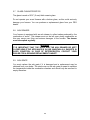
PSG 250, de Copenhague, St-Augustin-de-Desmaures (Quebec) CANADA G3A 2H3 Installation and operating instructions for the MINI-CADDY FURNACE PF01301 FURNACE MODELS INCLUDED IN THIS MANUAL: ADD-ON WOOD ONLY COMBINATION: WOOD/ÉLECTRIC (11.25 Kw) Read these instructions carefully before installing and operating your furnace. Please keep this document! Verified and tested for Canada and the United States by : Printed in Canada This manual is available for free download on the manufacturer’s web site. It is a copyrighted document. Re‐sale is strictly prohibited. The manufacturer may update this manual from time to time and cannot be responsible for problems, injuries, or damages arising out of the use of information contained in any manual obtained from unauthorized sources. 45533A 01-05-2013 THANK YOU FOR CHOOSING THIS PSG FURNACE As one of the biggest most respected furnace wood manufacturer in North America, PSG prides in the quality and performance of all its products. This manual is intended to help you in getting the most satisfaction out of the use of this product. In the following pages, you will be introduced to wood burning in general like starting, building and maintaining a fire. You will also find detailed installation instructions and recommendations on how to maintain your heating system in order to get the best performance out of your wood furnace. Congratulations for the judicious choice you made in buying a quality PSG product. Take the time to read this manual in its entirety before installing and operating your new furnace. It is important that you follow these installation instructions carefully. Failure to do so could result in a house fire, bodily injuries or even death. You may have to get a permit from the local authorities before installing this furnace and the chimney it will be connected to. Contact you local building inspector or fire department to know the particular requirements in your area. We also recommend that you contact your household insurance company to verify if the installation will have an incidence on your policy. REGISTER YOU WARRANTY ONLINE To receive full warranty coverage, you will need to show evidence of the date you purchased your furnace. Keep your sales invoice. We also recommend that you register your warranty online at www.psg-distribution.com Registering your warranty online will help us track rapidly the information we need on your furnace. 2 2 1.1 Table of content INTRODUCTION ....................................................................................... 6 1.2 CHIMNEY AND DRAFT ............................................................................. 7 PART A - SAFETY RULES .................................................................................... 8 2.1 GENERAL REQUIREMENTS ................................................................... 8 2.2 ODOUR FROM THE PAINT ...................................................................... 8 2.3 ASH DISPOSAL.......................................................................................... 8 2.4 CREOSOTE BUILD-UP AND REMOVAL ................................................. 8 2.5 SMOKE DETECTOR .................................................................................. 9 2.6 DOOR GLASS ............................................................................................. 9 2.7 GLASS CHARACTERISTICS ....................................................................10 2.8 ASH DRAWER ..........................................................................................10 2.9 ASH GRATE ..............................................................................................10 2.10 FLUE AND BAROMETRIC DRAFT CONTROL CONNECTION ............. 11 2.11 DAMPER ................................................................................................... 11 2.12 FRESH AIR INTAKE ................................................................................ 12 3 PART B - INSTALLATION .................................................................................. 14 3.1 WOOD ADD-ON ....................................................................................... 16 3.1.1 INSTALLATION MINI-CADDY ADD-ON ......................................... 16 3.1.2 INTRODUCTION ............................................................................... 16 3.1.3 APPLIANCE INSTALLATION ........................................................... 16 3.1.4 UNIT LOCATION ............................................................................... 16 3.1.5 MATCHING THE TRANSFER DUCT BETWEEN THE TWO HEAT GENERATORS ................................................................................... 17 3.1.6 BLOWER OF THE EXISTING FURNACE ........................................ 19 3.1.7 MINIMUM CLEARANCES TO COMBUSTIBLE MATERIALS FOR MINI-CADDY ADD-ON ..................................................................... 19 3.1.8 PIPE CONNECTOR AND DAMPER .................................................. 21 3.1.9 ELECTRICAL CONNECTIONS......................................................... 22 3.1.10 FAN LIMIT CONTROL ..................................................................... 22 3.1.11 SERVOMOTOR ................................................................................. 22 3.1.12 THERMOSTAT .................................................................................. 23 3.1.13 SAFETY PRECAUTION .................................................................... 23 3.1.14 OPERATING INSTRUCTIONS ......................................................... 23 3.1.15 INSTALLATION OF MINI-CADDY ADD-ON .................................. 24 3 3.1.16 INSTALLATION WITH AN EXISTING OIL FURNACE .................. 28 3.1.17 WIRING DIAGRAM FOR CONNECTION OF THE MINI-CADDY ADD-ON WITH AN EXISTING OIL FURNACE. .............................. 31 3.1.18 LOW VOLTAGE WIRING DIAGRAM FOR CONNECTION OF THE MINI-CADDY ADD-ON WITH AN EXISTING GAS OR ELECTRIC FURNACE. ........................................................................................ 32 3.1.19 MINI-CADDY ADD-ON TECHNICAL DATA ................................... 33 3.2 WOOD ONLY ........................................................................................... 35 3.2.1 MINI-CADDY WOOD ONLY INSTALLATION ................................ 35 3.2.2 UNIT LOCATION .............................................................................. 35 3.2.3 CLEARANCES TO COMBUSTIBLE MATERIAL ............................. 35 3.2.4 MINIMUM CLEARANCES REQUIRED FROM ANY COMBUSTIBLE MATERIAL FOR THE MINI-CADDY FURNACE. ........................... 35 3.2.5 ROUND HOT AIR PLENUM OPTION (PA07400) ...........................37 3.2.6 CONNECTING PIPE ..........................................................................37 3.2.7 PARALLEL INSTALLATION ............................................................ 38 3.2.8 ELECTRICAL CONNECTION ........................................................... 39 3.2.9 THERMOSTAT .................................................................................. 39 3.2.10 FAN LIMIT CONTROL ..................................................................... 39 3.2.11 OPÉRATION INSTRUCTIONS ......................................................... 40 3.2.12 CONTROL SYSTEM .......................................................................... 40 3.2.13 WIRING DIAGRAM ........................................................................... 41 3.2.14 MINI-CADDY TECHNICAL DATA ................................................... 42 3.2.15 GENERAL TECHNICAL DATA ........................................................ 42 3.2.16 TECHNICAL DATA – ELECTRIC MODE ........................................ 42 3.3 4 WOOD/ELECTRIC COMBINATION ...................................................... 44 3.3.1 MINI-CADDY WOOD/ELECTRIC INSTALLATION ....................... 44 3.3.2 INTRODUCTION .............................................................................. 44 3.3.3 MINIMUM CLEARANCES REQUIRED TO ANY COMBUSTIBLE MATERIAL........................................................................................ 45 3.3.4 ROUND HOT AIR PLENUM OPTION (PA07400) .......................... 45 3.3.5 ELECTRIC UNIT ............................................................................... 45 3.3.6 THERMOSTAT ...................................................................................47 3.3.7 WIRING DIAGRAM .......................................................................... 48 PART C – OPERATION........................................................................................ 49 4.1 LIGHTING................................................................................................ 49 4 5 6 7 4.2 PREHEATING .......................................................................................... 49 4.3 HEATING ................................................................................................. 50 4.4 FIRST SIGNS OF AN OVERHEATING FURNACE ................................ 50 4.5 WOOD AS A COMBUSTIBLE ................................................................... 51 4.6 CHIMNEY FIRE ........................................................................................ 51 4.7 LOCAL FIRE DEPARTMENT. ................................................................. 52 4.8 PROLONGED POWER OUTAGE ............................................................ 52 PART D - MAINTENANCE .................................................................................. 53 5.1 HEAT EXCHANGERS CARE ................................................................... 53 5.2 CHIMNEY MAINTENANCE.....................................................................55 5.3 SMOKE PIPE INSPECTION .....................................................................55 5.4 BLOWER MOTOR MAINTENANCE ........................................................55 5.5 FILTERS ....................................................................................................55 5.6 DOOR GASKET RELACEMENT ............................................................. 56 PART E – REMPLACEMENT PARTS ............................................................... 57 6.1 THE GLASS ............................................................................................... 57 6.2 THE DOOR GASKET ................................................................................ 57 6.3 MINI-CADDY BRICK LAYOUT ............................................................... 58 PART F - DUCTS AND DAMPERS DIMENSIONS .......................................... 59 7.1 DUCTS AND DAMPERS DIMENSIONS (EXAMPLES OF CALCULATION) ...................................................................................... 59 8 PART G - TROUBLESHOOTING ....................................................................... 60 9 PART H - SPECIFICATIONS .............................................................................. 61 10 APPENDIX A – ROUND HOT AIR PLENUM OPTION .................................. 62 WHY PURCHASE THROUGH AN AUTHORIZED PSG DEALER? .................... 63 PSG LIMITED LIFETIME WARRANTY (REGULAR) .......................................... 64 PSG LIMITED LIFETIME WARRANTY (PRIVILEGE) ........................................ 65 5 1.1 INTRODUCTION Take note that this furnace uses the same wood burning technology as a high efficiency EPA certified wood burning stove. This applies to the lighting, the ember bed, and the minimum combustion air intake which was calibrated to burn good seasoned cordwood. We recommend that our wood burning hearth products be installed and serviced by professionals who are certified in the United States by NFI (National Fireplace Institute®) or in Canada by WETT (Wood Energy Technical Training) or in Quebec by APC (Association des Professionnels du Chauffage). This model line is certified as meeting the emissions limits in 40 C.F.R. part 60, section 60.532 (B) per EPA methods 28 and 5G-3, February 1988. Taux d’émissions : 6.0 g/h Average efficiency: 84 % (LHV) To optimize the efficiency of your furnace, here is some advice that you should follow when installing or operating your MINI-CADDY furnace: Respect the local codes (when in doubt, consult your local dealer); Verify the specifications on the certification plate concerning the clearances to make sure that they correspond to the ones included in this instruction manual. Make sure your furnace is installed according to the instructions on the certification label; All controls and adjustments must be performed by a qualified technician. The blower speed must conform to the recommendations of the Warm Air Heating and Air Conditioning National Association and should respect the static pressure ranges in the warm air plenum of the furnace. WARNING THE INFORMATION GIVEN ON THE CERTIFICATION LABEL AFFIXED TO THE APPLIANCE ALWAYS OVERRIDES THE INFORMATION PUBLISHED, IN ANY OTHER MEDIA (OWNER’S MANUAL, CATALOGUES, FLYERS, MAGAZINES AND/OR WEB SITES). 6 1.2 CHIMNEY AND DRAFT This furnace must be connected to a chimney certified for wood burning heating appliances; a 6” connector and chimney is mandatory. If the chimney draft exceeds -0.06’’ w.c, a barometric draft control should be installed on the smoke pipe. Never install a manual damper. The barometric control must be adjusted so that the maximum draft measured at the furnace outlet does not exceed -0.06’’ w.c. Please note that a draft exceeding -0.06” w.c. will reduce the efficiency and could produce an uncontrollable fire. On the other hand, the minimum draft required is 0.04” w.c. in the evacuation pipe on the wood side, no matter what type of furnace. 7 2 PART A - SAFETY RULES 2.1 GENERAL REQUIREMENTS Make sure the chimney outlet and the pipes are clean and in good condition. DO NOT USE CHEMICAL PRODUCTS OR LIQUIDS TO LIGHT THE FIRE. DO NOT BURN WASTES OR FLAMMABLE LIQUIDS SUCH AS GASOLINE, NAPHTHA, MOTOR OIL, OR OTHER UNSUITABLE MATTERS. Do not install an automatic feeder on this furnace. Do not store wood in the vicinity of the furnace. Respect the required clearances between combustible materials and the source of heat. WARNING THE ASH DRAWER AND EXCHANGERS ACCESS PANEL GET VERY HOT. DO NOT MANIPULATE WITH BARE HANDS. 2.2 ODOUR FROM THE PAINT It is normal that smoke and odours emanate from the unit when you first light it. It is recommended to burn it at high rate and ventilate the building until the odours disappear. The smoke is not toxic. 2.3 ASH DISPOSAL Ashes must be placed in a metal container with a tight fitting lid. The container should be stored outdoors, well away from combustible materials. This container should not receive any other type of waste. If the ashes are meant to be buried in soil, wait until all embers have thoroughly cooled before burying. 2.4 CREOSOTE BUILD-UP AND REMOVAL When wood is burned slowly, it produces tar and other organic vapours which, when combined with moisture, form creosote. The creosote vapours condensate in a relatively cool chimney flue. As a result, creosote residues accumulate inside the flue lining and the exchangers. N.B.: To minimize the frequency of the chimney cleaning, buy your firewood at least one year before using it. Store it in a dry place in order to obtain the minimum moisture rate and optimize the efficiency. Do not store wood or combustible materials within the installation minimum clearances or the space required to reload the appliance and remove ashes. 8 When ignited, creosote produces an extremely hot fire inside the chimney. To avoid this situation, it is important to do the rotation of wood away from heating appliances and lighting products. Inspect the chimney system at regular intervals to determine a cleaning cycle. A weekly cleaning might be required during mild temperature periods but a monthly cleaning should be sufficient during cold periods. If a significant layer of creosote has accumulated, it must be removed immediately to eliminate the risk of chimney fire. (It is recommended to clean the heat exchangers thoroughly at the end of season in order to prevent corrosion). Remember that a small, hot fire is preferable to a large smouldering one to prevent creosote build-ups within the system. Prepare an emergency procedure in case of a chimney fire (See Section 4.6.) 2.5 SMOKE DETECTOR We highly recommend the use of a smoke detector. It must be installed at least 15 feet (4,57 m) from the appliance in order to prevent undue triggering of the detector when reloading. 2.6 DOOR GLASS To maintain a clean and safe installation, do not build your fire too close to the glass or allow logs to lean on the glass. Do not operate your furnace at too low a setting. Keep the air inlet opened long enough during the fire start-up to prevent the fire from smouldering, which could stain the glass. An intense fire will help keep the glass clean. However, in the event that your glass gets stained, which should not occur under normal operating conditions, you will have to clean it using a wet cloth and a wood stove glass cleaner. Clean the glass ONLY when the unit has cooled down. Do not use abrasive cleanser. Wood stove glass cleaners are available in most home centers and specialty hearth retailers. WARNING AVOID KNOCKING OR SCRATCHING THE GLASS. IT COULD CRACK OR BREAK. 9 2.7 GLASS CHARACTERISTICS The glass is made of 3/16” (5 mm) thick ceramic glass. Do not operate your wood furnace with a broken glass, as this could seriously damage your furnace. You can purchase a replacement glass from your PSG dealer. 2.8 ASH DRAWER Your furnace is equipped with an ash drawer to collect ashes produced by the combustion of wood. This drawer must not be left open during combustion as this may cause over firing and serious damages to the furnace. The drawer must be emptied regularly. WARNING IT IS IMPORTANT THAT THE DOOR AND THE ASH DRAWER BE KEPT CLOSED WHILE THE APPLIANCE IS IN USE. MAINTAIN ALL GASKETS IN GOOD CONDITION; IN CASE OF DETERIORATION, CONTACT YOUR DEALER FOR A GENUINE REPLACEMENT GASKET. 2.9 ASH GRATE You must replace the ash grate if it is damaged and a replacement may be obtained from your dealer. The steel cover on the ash grate is meant to optimize the temperature inside the combustion chamber and should only be removed to empty the ashes. 10 2.10 FLUE AND BAROMETRIC DRAFT CONTROL CONNECTION ATTENTION BEFORE CONNECTING THE STOVE PIPE, MAKE SURE YOU HAVE REMOVED THE SCRAPER FROM THE FLUE PIPE. For a proper installation, follow the advice below: 1- All the exhaust pipe joints must be secured with three screws. Make sure that each screw goes through the inner wall of both connectors (male and female). See pictures below showing a male-female coupling. CAUSES RESTRICTION PROPER INSTALLATION IMPROPER INSTALLATION 2- A minimum rise of ¼” per horizontal foot must be respected. 2.11 DAMPER The barometric damper must be adjusted so that the maximum draft measured at the furnace outlet is limited to -0.06 in. w.c. However, the minimum draft to be respected at all times is -0.04 in. w.c. in the evacuation pipe. WARNING DRAFT HIGHER THAN -0.06” W.C. MAY CAUSE AN UNCONTROLLABLE FIRE. 11 2.12 FRESH AIR INTAKE When the furnace and the chimney are completely cold, it may be necessary to provide fresh air by opening a door or a window for a few minutes while lighting the fire. Take note that a house constructed or renovated in order to be airtight may lack the volume of fresh air necessary for the proper combustion of a solid-fuel heating appliance. In such a case, when starting up the fire, do not operate appliances that evacuate air outside the house, such as: - Range hood - Air exchanger - Clothes dryer - Bathroom fan - Ventilated central vacuum system ATTENTION SUFFICIENT COMBUSTION AIR MUST BE AVAILABLE AT ALL TIMES; LACK OF COMBUSTION AIR CONSTITUTES A DANGER. NOTE: It is recommended to install an outside air inlet with a diameter of at least 4 inches in the room where the heating appliance is installed (see drawing next page). It is preferable to choose a wall which is not exposed to dominant winds, depending on the conditions surrounding your house. 12 INSULATED PIPE AIR SUPPLY AIR INLET EXTERIOR WALL N.B.: THE OWNER OF THE FURNACE IS RESPONSIBLE FOR THE ROOM’S AIR QUALITY IN CASE OF NEGATIVE PRESSURE OR TEMPORARY NEGATIVE PRESSURE. 13 3 PART B - INSTALLATION PART B of this manual contains installation instructions for the three types of Mini-Caddy furnace. You can consult only the section that applies to the furnace you have chosen. WOOD ADD-ON ........................................................... 15 WOOD ONLY ............................................................... 34 WOOD/ELECTRIC COMBINATION ............................. 43 14 MINI-CADDY ADD-ON PF01301 MINI-CADDY ADD-ON Installation Instructions 15 3.1 WOOD ADD-ON 3.1.1 INSTALLATION MINI-CADDY ADD-ON 3.1.2 INTRODUCTION MINI-CADDY ADD-ON The wood burning Mini-Caddy Add-on furnace is approved for in-line connection to an existing oil furnace with a firing rate of 0.8 G.P.H. (US) to 1.2 G.P.H. (US) or any gas or electric furnace with comparable heat output. The existing furnace must have a maximum heating capacity of 20,51 kW (75,000 BTU/h.) 3.1.3 APPLIANCE INSTALLATION Before installation, please read the instructions carefully and make sure you understand them: The furnace must be installed in a state of the art manner. Installation must be made in accordance with the CSA B.365 standard concerning the normalization of solid fuel units. If modifications have to be made to the existing furnace, these have to be conform respectively to CSA B.139 for oil furnaces, CSA C22.1 for electric furnace and CAN/CSA B149.1 or CAN/CSA B149.2 for gas furnaces. Inspect the furnace to make sure that nothing has been damaged in the shipping. Pull out the wiring kit and the instructions manual from the firebox of the furnace and the scraper from the flue pipe. 3.1.4 UNIT LOCATION The furnace must be installed where outside air supply will be sufficient for proper combustion. In airtight houses, it might be necessary to install an outside air inlet (see Section 2.12.) The furnace must be positioned so that the connector is as short as possible. Minimize the use of 90o elbows. The owner must ensure a proper installation to allow a safe operation of the appliance. 16 Install the plenum and heating ducts in line as in OPTION #1 de la Section 3.1.15. In series connection should be considered only if in line connection is not possible. If the ducts are installed in series (Section 3.1.15, OPTION #2) and the existing furnace’s fan limit control is mounted on the plenum, the divider in the plenum must be installed at least 5” (127 mm) above the fan limit control casing. This divider must be air tight. Do not install connecting ducts in a way that would allow inversion of the air flow. Do not use elbows with a radius less than 6 inches (153 mm). The transfer duct between the existing furnace and the add-on must be at least 260 square inches (0.16 m2) and deviations radius must be at least 6” (153 mm). (See OPTION #1 and #2 in Section 3.1.15). WARNING DO NOT CONNECT TO A DOWN FLOW FURNACE. WARNING DO NOT REMOVE, RELOCATE OR BYPASS ANY OF THE SAFETY CONTROLS IN THE ORIGINAL FURNACE INSTALLATION. You must determine the air flow through the existing furnace before installing the Mini-Caddy add-on: 1. Run the furnace to which the Mini-Caddy add-on is connected until it reaches its maximum temperature. 2. With a thermometer, measure the temperature of the cold air entering the furnace and that of the air exiting the furnace in the hot air plenum. Note: There can be a large lag in the readings of many commercially available thermometers. Give them adequate time to stabilize when taking temperatures. The temperature rise is obtained by subtracting the cold air return temperature from that of the air exiting in the hot air plenum. The result (t) will be needed for next step. 17 Install the plenum and heating ducts in line as in OPTION #1 and #2 of Section 3.1.15. Configurations shown in Examples 1, 2 and 3 of this same section are prohibited. MINI-CADDY ADD-ON 3.1.5 MATCHING THE TRANSFER DUCT BETWEEN THE TWO HEAT GENERATORS 3. Make the following verifications: a) Oil furnace: MINI-CADDY ADD-ON CFM = orifice size (SI)(liter/hour) x 39 023 x E 1.21 x t CFM = orifice size (Imperial)(gallon/hour) x 140 000 x E 1.1 x t E : Average heat generator efficiency (0.75) t: Temperature rise (ºC) b) Electric furnace: 1.21 Re = Electrical energy input rate, kW t = Temperature rise (ºC) c) Gas furnace: 1.21 Rg = Gas input rate, kW Eg = Efficiency of a typical atmospheric gas furnace (0.7) 4. After the installation of the add-on, the original numbers must be restored in order to maintain a constant air flow through the furnace. 18 Some adjustment on the motor and blower of the existing furnace may be necessary. In this case, the following rules apply: On a belt-driven system, blower pulleys and motor pulleys may be changed to do the adjustment. On a direct-drive system, the motor shall not be changed; however, the speed of the motor may be increased or decreased. CAUTION THE BLOWER OF THE EXISTING FURNACE ITSELF SHALL NOT BE CHANGED. WARNING THE ELECTRICAL CURRENT FLOWING THROUGH THE BLOWER MOTOR SHALL NOT EXCEED THE NAMEPLATE RATING. 3.1.7 MINIMUM CLEARANCES TO COMBUSTIBLE MATERIALS FOR MINICADDY ADD-ON N.B.: THIS APPLIANCE MUST BE INSTALLED IN ACCORDANCE WITH THE INSTRUCTIONS ON THE CERTIFICATION PLATE APPLIED ON THE UNIT. 19 The blower of the existing furnace shall produce an average air flow in the plenum in between 750 to 1,250 cfm when the external static pressure is adjusted to 0,2" of water column and in between 650 to 1100 cfm when adjusted to 0,5" of water column. MINI-CADDY ADD-ON 3.1.6 BLOWER OF THE EXISTING FURNACE MINI-CADDY ADD-ON Figure 3.1.7 a The furnace may be installed on a combustible floor. Figure 3.1.7 b - Reduced clearances of insulated ductwork 20 WARNING YOUR INSULATION INSTALLED ON THE DUCTWORK SHOULD NEVER BE IN CONTACT WITH ANY COMBUSTIBLE MATERIAL. THE CLEARANCE LISTED IN THE FIGURE ‘’REDUCED CLEARANCES OF INSULATED DUCTWORK’’ IS FROM THE TOP OF THE INSULATION. N.B.: THE AIR RETURN DUCTS SHOULD BE AT LEAST EQUAL TO THE COLD AIR PLENUM DIMENSIONS. MINI-CADDY ADD-ON The insulation allowed for this kind of installation must have an R-value in between 3.5 and 6.5. The thickness of insulation needed will differ from an insulation material to another. Figure 3.1.7 c - Hot air plenum minimal height. The hot air plenum coming out of the furnace is to have a minimum height of 24" (610 mm) if the top of the first vertical section is not flush with the first horizontal section (see Figure 3.1.7 c). Otherwise, the minimum height is 10" (254 mm). These dimensions for all hot air furnaces are in accordance with the standards CSA B140.4, UL 391 and UL 727. 3.1.8 PIPE CONNECTOR AND DAMPER The Mini-Caddy Add-on furnace must be connected to a duct system and a chimney that are in good condition; the use of separate chimneys is recommended. If the furnace is connected to an oil furnace and both appliances must share the same chimney, the chimney and smoke connector must be 7” in diameter and approved for use with wood-burning appliances. The use of 6” connector and chimney is permitted if the wood furnace evacuates into a separate chimney. It’s strictly forbidden to connect a solid fuel burning appliance to a chimney deserving a propane or natural gas appliance. Regulation CAN-CSAB365.1. DO NOT INSTALL A MANUAL DAMPER. 21 OIL PIPE REDUCER MINI-CADDY ADD-ON 7" DIAMETER 3.1.9 ELECTRICAL CONNECTIONS The following instructions do not replace those of the local code. Installation and verification of this appliance must be done by a qualified service man. 3.1.10 FAN LIMIT CONTROL Install the fan limit control on the back of your furnace. 3.1.11 SERVOMOTOR If the ducts are connected in series as per OPTION #2 in Section 3.1.15 and the fan limit control of the existing furnace is located in the plenum, the divider must be installed at least 5" (127 mm) above the fan limit casing. This divider must be airtight. All wiring and connections must be done according to the diagram. The controls of the two furnaces must be interconnected. WARNING ONLY USE WIRES SUITABLE FOR 75°C (167°F). 22 3.1.13 SAFETY PRECAUTION CAUTION THE OPERATION OF A GAS FURNACE MUST BE VERIFIED FOR ACCEPTABLE OPERATION BEFORE AND AFTER INSTALLATION OF THE MINI-CADDY ADD-ON APPLIANCE BY A GAS FITTER WHO IS RECOGNIZED BY THE REGULATORY AUTHORITY. CAUTION DO NOT CONNECT TO ANY GAS FURNACE THAT HAS NOT BEEN CERTIFIED INITIALLY AS COMPLYING WITH CGA STANDARD CAN/CGA2.3 OR ITS PRECEDENTS. 3.1.14 OPERATING INSTRUCTIONS Operate the existing furnace periodically to ensure that it will operate satisfactorily when needed. On the wood furnaces, the thermostat controls the air inlet damper. When the thermostat calls for heat, the damper opens and the combustion is stirred up. When the furnace gets hot enough, the fan limit control activates the blower motor at the speed selected for wood heating. 23 The thermostat must be installed on an inside wall in a location where it is not likely to be affected by the draft coming from an air outlet. It must be installed at a minimum of 55 inches above the floor. The two thermostats on a combined system must be installed at the same height. The Mini-Caddy wood Add-on furnace’s thermostat must be positioned between 18°C et 21°C (65°F et 70°F) or to a temperature slightly higher (2°C à 3°C) than the existing furnace. It controls the opening or closing of the air intake of the wood Add-on furnace. MINI-CADDY ADD-ON 3.1.12 THERMOSTAT 3.1.15 INSTALLATION OF MINI-CADDY ADD-ON MINI-CADDY ADD-ON *Minimum duct size 260 square inches * r = Minimum radius 6 inches 24 MINI-CADDY ADD-ON Example 1 Example 2 25 MINI-CADDY ADD-ON Example 3 To install the connecting duct from the existing furnace to the left or right side of your Mini-Caddy Add-on, unscrew the small access panel on the left side and secure it to the rear of the furnace with the same screws. 26 MINI-CADDY ADD-ON To install the connecting duct from the existing furnace to the left side of your Mini-Caddy Add-on, unscrew the big access panel on the left side (you may discard the panel). Connect the duct. To install the connecting duct from the existing furnace to the right side of your Mini-Caddy Add-on, unscrew the big access panel on the left side (see previous drawing) (you may discard the panel). Then remove the panel on the right side and secure it to the left side with the same screws. Connect the duct. Note: Before connecting the ducts from the existing furnace to either side of the Mini-Caddy Add-on, it is recommended to cut off the extra insulation (A) located behind the panel where connection will be made. 27 3.1.16 INSTALLATION WITH AN EXISTING OIL FURNACE Note: the fan limit control PA08522 (1) is not provided with the furnace and has to be purchased separately. MINI-CADDY ADD-ON To install the fan limit control assembly (1) (PA08522 not included with the furnace), remove the cover on the fan limit control and the cover on the junction box. Slide the fan limit control’s probe in the opening (2) provided for that purpose next to the flue outlet on the back of the furnace. Secure the fan limit control and junction box with screws (not supplied) in the holes intended for that purpose. Once the wiring as per Appendix 1 is completed, put the covers back on. 2 28 MINI-CADDY ADD-ON Run a cable (F) from your house electrical entrance to the fan limit control’s junction box. Note: It is recommended to connect the Mini-Caddy Add-on on the same circuit as the existing furnace. Pull the red and black wires (E) out of junction box through the wire grommet. 29 MINI-CADDY ADD-ON Run an 18-2 cable from the thermostat (A) of the Add-on to the fan limit assembly’s junction box (C). Run an 18-2 cable from the thermostat (A) of the existing oil furnace to the fan limit assembly’s junction box (C). Run an 18-2 cable from the servomotor (A) of the Add-on to the fan limit assembly’s junction box (C). Note: To perform the wiring, see WIRING DIAGRAM FOR CONNECTION OF THE MINI-CADDY ADD-ON WITH AN EXISTING OIL FURNACE (3.1.17). Note: For connection with an existing gas or electric furnace, remove the fan limit control (C) from the assembly and use it for low voltage wiring as per diagram 3.1.18. Connection with a gas or electric furnace will require the use of a SPDT 24 volt relay (White-Rogers 90-370 or the equivalent) not included. 30 MINI-CADDY ADD-ON 3.1.17 WIRING DIAGRAM FOR CONNECTION OF THE MINI-CADDY ADD-ON WITH AN EXISTING OIL FURNACE. 31 3.1.18 LOW VOLTAGE WIRING DIAGRAM FOR CONNECTION OF THE MINICADDY ADD-ON WITH AN EXISTING GAS OR ELECTRIC FURNACE. MINI-CADDY ADD-ON 32 MINI-CADDY ADD-ON 3.1.19 MINI-CADDY ADD-ON TECHNICAL DATA MINI-CADDY ADD-ON A 29 1/8" (740 mm) B 23 3/4" (603 mm) C 45 5/8" (1159 mm) D 12" (305 mm) E 12" (305 mm) F 40 1/4" (102 mm) G 19 3/4” (502 mm) H 13” (330 mm) FLUE * 6" (152 mm) WEIGHT 416 Lb (189 kg) * Reducer required GÉNÉRAL TECHNICAL DATA MODELE TEMP. BTU/HR VARIABLE (WOOD) STATIC PRESSURE MIN. (°F) MINI-CADDY ADD-ON MAX. H20 20 (67) 75 000 33 0,2 0,4 Installation instructions for MINI-CADDY WOOD ONLY PF01301 MINI-CADDY WOOD ONLY 34 3.2 WOOD ONLY 3.2.1 MINI-CADDY WOOD ONLY INSTALLATION 3.2.2 UNIT LOCATION The furnace must be installed where outside air supply will be sufficient for proper combustion. In airtight houses, it might be necessary to install an outside air inlet (see Section 2.12.) The owner must ensure a proper installation to allow a safe operation of the appliance. 3.2.3 CLEARANCES TO COMBUSTIBLE MATERIAL N.B.: THIS APPLIANCE MUST BE INSTALLED IN ACCORDANCE TO THE INSTRUCTIONS MENTIONED ON THE FURNACE’S CERTIFICATION PLATE. 3.2.4 MINIMUM CLEARANCES REQUIRED FROM ANY COMBUSTIBLE MATERIAL FOR THE MINI-CADDY FURNACE. MINI-CADDY WOOD ONLY The furnace must be positioned so that the connector is as short as possible. Minimize the use of 90o elbows. Figure 3.2.4 a 35 N.B.: THE VOLUME OF COLD AIR RETURN SHOULD BE AT LEAST EQUAL TO THE VOLUME OF THE HOT AIR DISTRIBUTION. MINI-CADDY WOOD ONLY Figure 3.2.4 b N.B.: THE SIZE OF THE AIR RETURN CONDUITS SHOULD BE AT LEAST EQUAL TO THE SIZE OF THE COLD AIR PLENUM OPENING. To ensure adequate static pressure, the amount of cold air return should exceed the amount of hot air distribution of at least 5%. Figure 3.2.4 c - Hot air plenum minimal height. The hot air plenum coming out of the furnace is to have a minimum height of 24" (610 mm) if the top of the first vertical section is not flush with the first horizontal section (see Figure 3.2.4 c). Otherwise, the minimum height is 10" (254 mm). These dimensions for all hot air furnaces are in accordance with the standards CSA B140.4, UL 391 and UL 727. 36 3.2.5 ROUND HOT AIR PLENUM OPTION (PA07400) See APPENDIX A. 3.2.6 CONNECTING PIPE ATTENTION DO NOT INSTALL A MANUAL DAMPER ON THIS FURNACE. MINI-CADDY WOOD ONLY The flue outlet on the Mini-Caddy furnace is 6 inch inside diameter. In case of excessive draft, a barometric draft control must be installed. The barometric drafty control must be set so that the draft measured at the furnace outlet does not exceed -.06 in. W.C. Draft above -.06 in W.C. could result in an uncontrollable fire and furnace overheat. However, draft should not drop below .04 in W.C. in the smoke pipe. 37 3.2.7 PARALLEL INSTALLATION Parallel installation with another furnace that shares the same ducts system is not permitted in Canada. That type of installation is permitted in the USA only. In parallel installation, the maximum heat input of the existing gas, oil or electric furnace should be equal or superior to that of the wood furnace. Duct clearances must be respected as if the wood furnace was installed a by itself. Necessary adjustments must be made to the distribution ducts so as to maintain static pressure between 0.20 and 0.05 in W.C. A back flow damper must be installed in order to make sure that the hot air circulates to the house and does not flow back through the plenum of the unused furnace. Depending on the type of installation, a damper may have to be installed in the plenum of both furnaces. MINI-CADDY WOOD ONLY 38 3.2.8 ELECTRICAL CONNECTION The following instructions do not replace those of the local code. Installation and verification of this appliance must be done by a qualified technician. Installation of the Mini-Caddy wood only furnace requires the use of the ``fan limit assembly for wood only`` option (PA00500) which must be purchased separately. Plastic grummets are installed on the upper edge of the blower box through which the blower cable (prewired 14-3 BX) will run before reaching the junction box located next to the blower where it will be connected. The low voltage control circuit will be fed from the transformer attached to the junction box of the fan limit assembly and the 120 volts circuit from the house electrical entrance will also be connected to that junction box as per the wiring diagram (31.2.13). ATTENTION USE WIRES SUITABLE FOR 75° C OR MORE. MINI-CADDY WOOD ONLY This option includes the fan limit control; install the fan limit control on the back of the furnace, next to the flue outlet where there are holes to insert the probe and secure the assembly. It is normal that the fan limit control is not vertical once installed. 3.2.9 THERMOSTAT The thermostat must be installed on an inside wall in a location where it is less likely to be affected by the draft coming from an air outlet. It must be installed at a minimum of 55 inches above the floor 3.2.10 FAN LIMIT CONTROL The fan limit control settings may need to be adjusted depending on the installation but they are set at 110 °F (fan off) and 150 °F. (Fan on) at the factory and these settings will work best in most installations. The adjustment of all controls must be performed by a qualified technician. The controls setting and the blower speed must conform to the recommendations of the “Warm Air Heating and Air Conditioning National Association”. For continuous operation of the blower, use the switch located below the fan limit 39 control which controls the low speed either at the “on” position or the “off” position. It is not recommended to let the blower run on continuous mode when heating with wood since the wood furnace must reach a certain temperature before the blower starts in order to operate efficiently. 3.2.11 OPÉRATION INSTRUCTIONS 3.2.12 CONTROL SYSTEM On wood only furnaces, when the thermostat calls for heat, the air inlet damper opens and the fire stirs-up; when the temperature inside the furnace is sufficient, the fan limit control will turn the blower on at the speed selected for wood heating and this one will stay on until the temperature drops down to the fan off setting. MINI-CADDY WOOD ONLY 40 MINI-CADDY WOOD ONLY 3.2.13 WIRING DIAGRAM 41 3.2.14 MINI-CADDY TECHNICAL DATA MINI-CADDY WOOD ONLY MINI-CADDY A B C D E MINI-CADDY 44 1/4” (112 cm) 12” (305 mm) 23 3/4” (60 cm) F G 40 1/4” (102 cm) 45 5/8” (116 cm) FLUE 6” (15 mm) WEIGHT 462 Lb (210 kg) 13 3/8” x 22” (34 X 56 mm) 12” (305 mm) 3.2.15 GENERAL TECHNICAL DATA MODEL DEBIT (DIRECT DRIVE) VENT MOT. VIT. (CFM) TEMP VAR. BTU/ H O ( F) (BOIS) STATIC PRESSURE MIN. MAX. FILTER (2) H2O MINICADDY DCT-916-800-5 ¼ HP 4 1100 67 73900 0.2 0.4 15’’ x 20’’ x 1’’ 3.2.16 TECHNICAL DATA – ELECTRIC MODE MODEL 11.25 KW BOIS DÉBIT (CFM) TEMP. VAR. (OF) BTU/H TOTAL AMPERAGE BREAKER ALIMENT. CALIBRE VOLTAGE 1 PHASE 1100 67 38400 45 60 6 120/240 2 15 14 120 42 # OF ÉLÉMENTS 4 x 3.75 KW Installation instructions for MINI-CADDY WOOD/ELECTRIC MINI-CADDY WOOD/ELECTRIC PF01301 43 3.3 WOOD/ELECTRIC COMBINATION 3.3.1 MINI-CADDY WOOD/ELECTRIC INSTALLATION 3.3.2 INTRODUCTION The fan limit assembly for wood only (PA00500) is not required for this installation. The 11.25 kW electric unit option includes everything you need for wood/electric installation. The fan limit control must be installed next to the flue outlet as in the wood only installation and only one cable (14-4) cable is attached to it; this cable will run inside the furnace through the plastic grommets installed on the upper edge of the blower box and then through the knock-outs in the rear panel of the furnace. Refer to the wiring diagram (3.3.8) for connections Another cable (14/3) is included and will be used to connect the blower to the power block in the electric unit as shown in the wiring diagram. Run this cable through the knock-outs in the rear panel of the furnace and the electric unit. The low voltage control circuit web e hooked up to the command block (numbered 1 to 8) as shown in the wiring diagram. The feeder cable (6-3) will enter the electric unit using a suitable cable connector through the left front panel of the unit and will be connected to the terminal block (L1, N, L2) of the unit. MINI-CADDY WOOD/ELECTRIC ATTENTION USE WIRES SUITABLE FOR 75° C OR MORE. You electric unit includes two protection devices against overheating; one Automatic reset L-200 and one manual reset L-250 thermodiscs. In some first generation furnaces, the L-200 automatic reset heat sensor is absent and a second fan limit control is included that is used for the same purpose. To install this fan limit control, remove the knock-out located on the left side of the furnace near the electric unit, insert the probe in the hole, secure the fan limit control to the furnace and connect the cable (14-2) inside the electric unit at the same location as the L-200 on the diagram. 44 3.3.3 MINIMUM CLEARANCES REQUIRED TO ANY COMBUSTIBLE MATERIAL. See Section 3.2.4. 3.3.4 ROUND HOT AIR PLENUM OPTION (PA07400) See Appendix A. 3.3.5 ELECTRIC UNIT The wood/electric combination model uses two wall thermostats; one controls the electric heat and the other one the wood heat. In this configuration, the electric heat has priority over the wood so whenever there is a call for heat from the electric thermostat, the air intake damper closes, the blower kicks on and the electric elements turn on in sequence 3.75 kW at the time. Refer to wiring diagram included with the electrical unit. When the demand for electric heat is satisfied, the wood system will be reactivated if the wood thermostat is set higher than the electric thermostat. This furnace’s blower uses a four speed motor; one speed (LOW) is controlled by the manual switch for summer operation. Three heating speeds are available (MED-LOW, MED_HIGH AND HIGH) and will be selected according the duct size and the needs for ventilation. If the temperature in the electric unit reaches 200°F, the L-200 thermodisc (or the second fan limit control) will cut the power to the elements until the furnace cools down and will turn the power back on automatically if there is still a call for heat. Should the temperature keeps rising, when it reaches 250°F, the L-250 manual reset thermodisc will cut the power off and it will have to be reset manually. Find and correct the cause of overheating before reactivating the unit. MINI-CADDY WOOD/ELECTRIC In normal wood/electric operation, the wood thermostat should be set slightly higher (3°C or 5°F) than the electric thermostat to allow the wood furnace to stabilize the temperature before the electric thermostat calls. The bigger the increment, the more wood will contribute to the global heating needs. 45 Red button manual reset L-250 Thermodisc manual reset INSIDE VIEW OF THE ELECTRIC UNIT MINI-CADDY WOOD/ELECTRIC OUTSIDE VIEW OF THE ELECTRIC UNIT 46 3.3.6 THERMOSTAT The thermostat must be installed on an inside wall in a location where it is less likely to be affected by the draft coming from an air outlet. It must be installed at a minimum of 55 inches above the floor MINI-CADDY WOOD/ELECTRIC N.B.: THE WOOD/ELECTRIC USES TWO THERMOSTATS INSTALLED AT THE SAME HEIGHT FROM THE FLOOR. 47 3.3.7 WIRING DIAGRAM MINI-CADDY WOOD/ELECTRIC 48 4 PART C – OPERATION 4.1 LIGHTING WARNING NEVER USE CHEMICALS OR FLAMMABLE LIQUIDS TO LIGHT THE FIRE 1. Open the door. Note: if there already is a bed of embers in the combustion chamber, proceed directly to the PREHEATING step. 2. Place 1 or 2 dry kindling at the front of the combustion chamber. 3. Lay a few strips of newspaper over the kindling. 4. Cover the paper with criss-crossed dry kindling. 5. Add more newspaper strips and light the paper at 2 or 3 different spots as low as possible and leave the door opened about ½ inch until the fire is burning well. If lighting fails, some smoke could spill out of the furnace through the air inlets. 4.2 PREHEATING 1. Once the kindling are burning well or the ember bed stirred up, lay 2 or 3 pieces of seasoned cordwood down in a way that the flame can circulate around the logs (split wood ignites faster than round logs with the bark) and close the door. Following this procedure will help the fire burn efficiently from the front to the back of the combustion chamber. 2. Wait 15 to 20 minutes before fully loading the furnace. 49 4.3 HEATING 1. Poke the fire and spread the embers evenly at the center of the combustion chamber before adding more wood. 2. Avoid overfilling the combustion chamber; air must be allowed to circulate freely through the upper portion of the chamber for the stove to perform best. Also remember that a small hot fire burns cleaner than a big smoldering one. IMPORTANT WHEN RELOADING, MAKE SURE YOU KEEP THE AIR INLETS LOCATED BELOW THE DOOR INSIDE THE COMBUSTION CHAMBER FREE OF ASH. OPENING PROCEDURE FOR THE LOADING DOOR TO MINIMISE THE RISK OF SMOKE SPILLAGE, CRACK THE DOOR OPEN ABOUT AN INCH AND WAIT ABOUT 10 SECONDS BEFORE OPENING IT WIDE TO ALLOW STABILISATION OF THE PRESSURE INSIDE THE FURNACE. 4.4 FIRST SIGNS OF AN OVERHEATING FURNACE 1. The fire rumbles. 2. The smoke pipe turns red. 3. Extreme heat emanates from the furnace. IF this happens, DO NOT OPEN THE DOOR, close the air inlet completely and wait for the fire to die down. WARNING ALWAYS KEEP THE DOOR AND ASH DRAWER CLOSED EXCEPT FOR LIGHTING’ RELOADING AND SERVICING THE FURNACE 50 4.5 WOOD AS A COMBUSTIBLE WARNING NEVER BURN GARBAGE, GASOLINE, NAPHTA, MOTOR OIL OR ANY SIMILAR FLAMMABLE PRODUCTS IN THIS FURNACE. We recommend that you only burn well seasoned cordwood in your furnace. Two important factors should be considered when buying cordwood; water content and density of the wood. Hard wood like oak, maple or beech give better results given their higher density and the less tar the produce during combustion. It is strongly recommended to let your wood dry in a place where it is exposed to sun and open air but protected precipitations. DO NOT BURN COAL IN THIS FURNACE.. If you notice a significant quantity of smoke in the house: 1. Open windows and doors. 2. Make sure the furnace door and the air inlet are closed (if need be, lower the thermostat setting or unhook the air intake damper connecting rod) and manually CLOSE the barometric draft damper. 3. Once the furnace has cooled down, check for possible obstructions in the exchangers, the smoke pipe and the chimney or call a specialist to determine the cause of the spillage and the way to prevent it from happening again. WARNING CARBON MONOXYDE IS A LETHAL GAS (ODORLESS AND COLORLESS), THAT YOU MUST FEAR. 4.6 CHIMNEY FIRE A Chimney fire will happen when the flame from an uncontrollable fire ignites the sooth and creosote deposits in a neglected venting system. It will often happen when burning cardboard, branches or small dry pieces of wood. The first signs of a chimney fire are: 1. A rumble. 2. Smoke pipe becomes extremely hot. 3. Sparks or even flames shoot out of the chimney 51 In the event of a chimney fire, first call your local fire department and water the roof in the vicinity of the chimney. Make sure that the furnace door and the air intake damper are closed (if need be, lower the thermostat setting or unhook the air intake damper connecting rod). CLOSE the barometric draft damper manually if one is installed. In the event of uncontrollable fire (caused by wrongful operation or excessive chimney draft), follow the same procedure as in a chimney fire but you must then OPEN the barometric draft damper manually if one is installed. 4.7 LOCAL FIRE DEPARTMENT. Telephone: ___________________________________ 4.8 PROLONGED POWER OUTAGE To reduce the risk of overheating during a prolonged power outage (more than 10 minutes), it is recommended to: Make certain that the air intake damper is closed. Open the blower access panel and remove the air filter to improve the circulation of air around the combustion chamber through natural convection. 52 5 PART D - MAINTENANCE 5.1 HEAT EXCHANGERS CARE Heat exchangers must be cleaned thoroughly at the end of every heating season. During summer, the air in basements is damper and with minimal air circulation within the furnace, it can mix with creosote and/or sooth deposits in the exchangers to form an acid that could accelerate the corrosion process and induce premature decay of the steel. Corrosion damages are not covered under warranty. Smoke pipe and exchangers must be inspected regularly during the heating season. Access to the exchangers is easy and does not require tools; just remove the decorative facing by just lifting it, remove the wing nut that keeps the hinged access panel closed. (See pictures below) 53 Before cleaning the three exchanger pipes (3), pull the baffle forward as on the drawing below. Using the scraper (1) clean all three pipes. The dirt in the lateral pipes can be pushed forward and it will fall directly into the combustion chamber while the dirt in the central pipe will have to be retrieved either from the front access panel or the rear by removing the smoke pipe. Verify that the baffle is free of deposits and do not forget to push it back to its original position. Finally, close the exchangers’ access panel. Cut view of the Mini-Caddy interior. 54 5.2 CHIMNEY MAINTENANCE The most efficient way to sweep a chimney is to run a hard chimney sweeping brush. Brush from the top down so sooth and creosote deposits will detach from the chimney liner and fall down to the bottom of the chimney where it can be easily removed. The chimney must be inspected regularly and any creosote build-up must be removed without delay. Monthly cleaning should be sufficient during cold winter months while more frequent cleaning could be required during milder periods. 5.3 SMOKE PIPE INSPECTION The smoke pipe must be inspected regularly during the heating season. The pipe must be examined carefully to detect any defect or damage. The pipe can be reassembled if no defect is detected and defective pipe must be replaced immediately. Burn wood only in this furnace. As a combustible, well seasoned hardwood in 18" logs works best. 5.4 BLOWER MOTOR MAINTENANCE After 3 seasons of operation, lubricate the motor annually with a few drops of 5W30 oil. DO NOT OVERLUBRICATE 5.5 FILTERS Never use the furnace without air filters. To function as expected, controlled combustion wood burning appliance must be maintained on a regular basis. This means that the chimney, the gaskets and the pipes must be kept in good working order and the air filter cleaned or replaced regularly. Use the same size and type of filter as the original. Air filter dimensions 15" x 20" Filters (Mini-Caddy) #21044 55 5.6 DOOR GASKET RELACEMENT It is important to keep the door gasket in good condition. The door is adjusted at the factory to seal the door tight. After a while, the gasket could sink and the door must then be adjusted as described below. If the door still leaks after the maximum adjustment, replace the gasket. Door adjustment procedure: 1. Remove the blockage pin by turning and pulling it out with pliers. 2. Turn the handle counter clockwise to increase the pressure between the door gasket and the stove body. 3. Reinstall the blockage pin by hammering it in carefully. 56 6 PART E – REMPLACEMENT PARTS Your PSG furnace was designed to burn clean with therefore require minimal cleaning. It is good to visually check the furnace once a month for damaged or defective parts. Any required repair should be made without delay using genuine PSG parts. An exploded view and complete parts list is available for you on the PSG web site at www.psg-distribution.com. 6.1 THE GLASS • Check the glass regularly to detect any crack or damage. Replace damaged glass immediately; do not use the furnace with a broken glass. • The glass on your furnace is made of 5mm (3/16") thick transparent ceramic. If the glass on your furnace has to be replaced, preferably use the original glass sold by your PSG dealer or replace it with the same type of material. • To replace the glass, remove the screws that hold the glass retainers to the door frame and remove the retainers. Replace the damaged glass by the new one and reinstall the retainers. The genuine glass sold by your dealer will have a new gasket installed on it; make sure you install a new gasket if you do not use the PSG replacement part. • Never clean the glass with a product that could scratch it. Use a stove glass cleaner available in most stores that sell wood stoves. • Clean the glass only when it is cold. 6.2 THE DOOR GASKET It is recommended to replace the gasket that seals the door once a year to insure a good control of the combustion and the maximum safety and efficiency. To replace the door gasket, remove the damaged gasket and scrape the dried glue out of the groove where it layed. Spread a small amount of gasket glue or high temperature silicone. Lay the new gasket in the groove. Wait at least 2 hours before relighting the stove. 57 6.3 MINI-CADDY BRICK LAYOUT # BRICK LAYOUT QTY 1 BRICK 1 1/16" x 6 3/4" x 1 1/4" (HD) 2 2 BRICK 2 1/8" x 9" x 1 1/4" (HD) 4 3 C‐CAST BAFFLE BOARD 1 4 ASH GRATE 1 5 BRICK 4" x 8" (HD) 8 6 BRICK 4" x 9" (HD) 9 7 BRICK 4 1/2" x 9" (HD) 5 58 7 PART F - DUCTS AND DAMPERS DIMENSIONS 7.1 DUCTS AND DAMPERS DIMENSIONS (EXAMPLES OF CALCULATION) SIMPLIFIED METHOD DISTRIBUTION SYSTEM HOUSE DIMENSIONS Example: 28 x 40 bungalow = Ducts size (heat) 4 inch outlet reduce by 1” 5 inch outlet reduce by 2” 6 inch outlet reduce by 3” Always by 8” thick N.B.: The main duct must be reduced every 2 outlets. Ducts specifications (heat) Dimensions Length Elbow 4” 5” 6” 10’ 10’ 10’ WARM AIR SYSTEM INSTALLATION o 1 x 90 1 x 90o 1 x 90o Average equivalence Max 4,000 Btu Max 6,000 Btu Max 7,000 Btu 1,120 sq. ft. 28 x 40 x 8 = 8,960 sq. ft. x 1.8 Ch. air/hr: 16,128 Btu Exposed walls : 40 + 40 + 28 + 28 = 136 x 8 = 1,088 sq. ft. x 22 = 23,936 Btu Number of windows : 12 of 3 x 4 = 144 x 60 = 8,640 Btu Number of doors : 2 x 3’ x 7’ = 42 x 100 = Non-insulated basement: 25 % Insulated basement: 15 % 4,200 Btu 52,904 Btu 7,906 Btu DAMPER Or 54 Btu per sq. ft. For a 4” warm air outlet: 2” x 10” damper FOR ELECTRIC ELEMENTS 80% = 48,672 Btu or 14,28 kW For a 5” warm air outlet: 2” x 12” damper or 4” x 10” For a 6” warm air outlet: 2” x 14” damper or 4” x 12”” 60,840 Btu TO BE ADDED: House 1 1/2 floor = 25 % House 2 floors = 40 % BEDROOM (for example: 12 x 12) 12 x 12 x 8 = 1,152 sq. ft. x 1.8 Ch. air/h = 2,074 Btu Exposed walls: 12 + 12 x 8 : 192 x 22 = 4,224 Btu Windows: 3 x 4 x 60 = 720 Btu 7 59 8 PART G - TROUBLESHOOTING PROBLEM CAUSES SOLUTIONS Heating inefficient during the first combustions. Lack of draft. Improper adjustment of the barometric damper (opened too wide). Chimney flue restriction (too long. 90o elbows) Adjust the damper, minimize the smoke pipe length and use 45o elbows. Furnace burns well, warm air plenum is very hot by there is not much heat coming out in the room. Improper installation of the ducts, low static pressure, unbalanced system (too many warm air outlets and not enough cold air inlets). Rearrange the ducting to respect the minimum static pressure of 0.20 in. w.c. Furnace consumes a lot of wood. The thermostat which controls the damper is continuously activated or is too close to a source of cold air. Damper not properly adjusted. House not insulated enough. Ash drawer is not tightly closed. Furnace too small for the surface to be heated. Unbalanced ventilation system, very little heat where the thermostat is located. Relocate the thermostat. Adjust the chain that links the damper to the servo-motor. Rebalance the ventilation system in order to increase the air flow in the room where the thermostat is located. Fan start-up is too slow. Fan “ON” setting too high. Return air is too cold (temperatures lower than 65 degrees). Limit control not well located on the furnace. Lower the temperature starting point. Usually, the limit control is set at 150 degrees, we can under certain conditions, reduce this temperature. Reduce the fresh air flow. Relocate the limit control. A lot of creosote, moderate heat output. Wet wood, lack of draft. Barometric damper not properly adjusted. Sooted up chimney. Use dry wood. Adjust the barometric damper. Clean the chimney, flue pipe and the furnace exchangers. Furnace heats a lot but the warm air plenum does not get hot. Wet wood or low grade wood. No static pressure. Unbalanced ventilation system. Use dry wood. Rearrange the ventilation system correctly. IMPORTANT NOTE FOR, INSTALLATION OF A CENTRAL HEATING VENTILATION SYSTEM, IT IS HIGHLY RECOMMENDED TO CONSULT A HEATING SYSTEM VENTILATION SPECIALIST. N.B.: STOVE BUILDER INTERNATIONAL INC. IS NOT RESPONSIBLE FOR POOR APPLIANCE PERFORMANCES, DUE TO IMPROPER INSTALLATION. 60 9 PART H - SPECIFICATIONS Furnace and components Combustible Maximum heat input Maximum heat output Average heat output Thermostatic control Maximum efficiency Average emissions Loading capacity Flue outlet size Recommended smoke pipe dimension Recommended chimney type Recommended chimney size Outside dimensions of the furnace Dimensions of the firebox Dimensions of the door opening Type of door Dimensions of the hot air plenum Dimensions of the cold air plenum Dimensions of ash drawer Number of filters Dimensions of the filters Blower (Wood or wood/electric options only) Thickness of steel (firebox) Minimum clearance (in front of furnace) Minimum clearance (rear of furnace ) Minimum clearance (sides of furnace ) Minimum clearance (standard ducts Recommended service clearance Weight Color Warranty Standards – security Standards – emissions / efficiency Maximum log length MINI-CADDY Bois 75,000 BTU (21.6 kW) 63,750 BTU (18.7 kW) 41,440 BTU (12.2 kW) YES 84% (LHV) / 78% (HHV) 6 grams/hr or 0,275 g/MJ Up to 30 lbs (14 kg) 6” (152 mm) 6” (152 mm) 2100 °F (1150 °C) 6” (152 mm) 23 1/4”L x 39 3/4”D x 45 5/8”H 14”L x 19 3/8”D x 12”H 13 1/2”L x 9 5/8”H Cast iron with ceramic glass 12" x 12" or 12" round with PSG optional distribution box 22 3/8"W x 13 5/8"L or adaptor with 8 round 5" outlets (supplied with the PSG optional distribution box ) 11 3/4”L x 12”D x 2 5/8”H 1 15”L x 20”P x 1”H 1/4 HP Direct drive 4 speeds 3/16” (5 mm) 48” 24” recommended service clearance 24” recommended service clearance 3” for the first 6 feet and 1” after 24” 405 lb s(184 kg) Black Limited lifetime Can CSA B366.1-M91, CSA C22.2 No. 236, UL 1995, UL391 3rd Ed. rev. 1999 EPA / CSA B415.1 18” Optionnal electric unit Heat output Unit location Unit’s recommended service clearance MINI-CADDY 11.25 kW Left 24” 61 10 APPENDIX A – ROUND HOT AIR PLENUM OPTION It is possible to install the round hot air plenum option (PA07400) on your furnace. This option may be ordered from our PSG dealer. 62 WHY PURCHASE THROUGH AN AUTHORIZED PSG DEALER? To make sure your PSG furnace provides comfort and energy savings in your home for many years, your choice of installer is extremely important. An authorized PSG dealer will ensure that the system is optimized and installed according to standards. Given the importance of the installation, PSG recommends that it is carried out by a professional certified in the Building Code so that the furnace delivers its full potential. This is why PSG offers an additional warranty that covers the cost of labor if your furnace has been purchased through an authorized PSG dealer. If you want to enjoy the best service on the market and substantial savings on heating costs, there is really only one choice: an Authorized PSG Dealer. 63 PSG LIMITED LIFETIME WARRANTY (REGULAR) The warranty of the manufacturer extends only to the original consumer purchaser and is not transferable. This warranty covers brand new products only, which have not been altered, modified nor repaired since shipment from factory. Proof of purchase (dated bill of sale), model name and serial number must be supplied when making any warranty claim to your PSG dealer. This warranty applies to normal residential use only. Damages caused by misuse, abuse, improper installation, lack of maintenance, over firing, negligence or accident during transportation, power failures, downdrafts, or venting problems are not covered by this warranty. This warranty does not cover any scratch, corrosion, distortion, or discoloration. Any defect or damage caused by the use of unauthorized parts or others than original parts void this warranty. An authorized qualified technician must perform the installation in accordance with the instructions supplied with this product and all local and national building codes. Any service call related to an improper installation is not covered by this warranty. The manufacturer may require that defective products be returned or that digital pictures be provided to support the claim. Returned products are to be shipped prepaid to the manufacturer for investigation. If a product is found to be defective, the manufacturer will repair or replace such defect. Transportation fees to ship the product back to the purchaser will be paid by the manufacturer. All parts costs covered by this warranty are limited according to the table below. The manufacturer at its discretion may decide to repair or replace any part or unit after inspection and investigation of the defect. The manufacturer may, at its discretion, fully discharge all obligations with respect to this warranty by refunding the wholesale price of any warranted but defective parts. The manufacturer shall in no event be responsible for any special, indirect, consequential damages of any nature, which are in excess of the original purchase price of the product. A one-time replacement limit applies to all parts benefiting from a lifetime coverage. This warranty applies to products purchased after April 1st, 2013. WARRANTY APPLICATION PARTS LABOUR DESCRIPTION Castings, combustion chamber (welds only), castings, and heat exchanger (welds only). Stainless steel firebox components, secondary air tubes*, surrounds and heat shields, ash drawer, and plating* (defective manufacture). Carbon steel firebox components, glass retainers, handle assembly, C-Cast baffle*, and vermiculite baffle*. Oil burner, electrical elements, blowers, heat sensors, switches, rheostat, relays, damper motor, fan limit control, PC board, wiring, and other controls. Ceramic glass (thermal breakage only*), paint (peeling), gaskets, insulation, and ceramic fibre blankets. Firebrick *Pictures required Lifetime n/a 5 years n/a 3 years n/a 2 years n/a 1 year n/a n/a n/a Shall your unit or a components be defective, contact immediately your PSG dealer. Prior to your call make sure you have the following information necessary to your warranty claim treatment: Your name, address and telephone number; Bill of sale and dealer’s name; Serial number and model name as indicated on the nameplate fixed to the back of your unit; Nature of the defect and any relevant information. Before shipping your unit or defective component to our plant, you must obtain from your PSG dealer an Authorization Number. Any merchandise shipped to our plant without authorization will be refused automatically and returned to sender. 64 PSG LIMITED LIFETIME WARRANTY (PRIVILEGE) The warranty of the manufacturer extends only to the original consumer purchaser and is not transferable. This warranty covers brand new products only, which have not been altered, modified nor repaired since shipment from factory and purchased through an authorised dealer. Proof of purchase (dated bill of sale), model name and serial number must be supplied when making any warranty claim to your PSG dealer. This warranty applies to normal residential use only. Damages caused by misuse, abuse, improper installation, lack of maintenance, over firing, negligence or accident during transportation, power failures, downdrafts, or venting problems are not covered by this warranty. This warranty does not cover any scratch, corrosion, distortion, or discoloration. Any defect or damage caused by the use of unauthorized parts or others than original parts void this warranty. An authorized qualified technician must perform the installation in accordance with the instructions supplied with this product and all local and national building codes. Any service call related to an improper installation is not covered by this warranty. The manufacturer may require that defective products be returned or that digital pictures be provided to support the claim. Returned products are to be shipped prepaid to the manufacturer for investigation. If a product is found to be defective, the manufacturer will repair or replace such defect. Transportation fees to ship the product back to the purchaser will be paid by the manufacturer. Repair work covered by the warranty, executed at the purchaser’s domicile by an authorized qualified technician requires the prior approval of the manufacturer. Labour cost and repair work to the account of the manufacturer are based on predetermined rate schedule and must not exceed the wholesale price of the replacement part. All parts and labour costs covered by this warranty are limited according to the table below. The manufacturer at its discretion may decide to repair or replace any part or unit after inspection and investigation of the defect. The manufacturer may, at its discretion, fully discharge all obligations with respect to this warranty by refunding the wholesale price of any warranted but defective parts. The manufacturer shall in no event be responsible for any special, indirect, consequential damages of any nature, which are in excess of the original purchase price of the product. A one-time replacement limit applies to all parts benefiting from a lifetime coverage. This warranty applies to products purchased after April 1st, 2013. WARRANTY APPLICATION PARTS LABOUR DESCRIPTION Castings, combustion chamber (welds only), castings, and heat exchanger (welds only). Stainless steel firebox components, secondary air tubes*, surrounds and heat shields, ash drawer, and plating* (defective manufacture). Carbon steel firebox components, glass retainers, handle assembly, C-Cast baffle*, and vermiculite baffle*. Oil burner, electrical elements, blowers, heat sensors, switches, rheostat, relays, damper motor, fan limit control, PC board, wiring, and other controls. Ceramic glass (thermal breakage only*), paint (peeling), gaskets, insulation, and ceramic fibre blankets. Firebrick *Pictures required Lifetime 3 years 5 years 3 years 3 years 1 year 2 years 1 year 1 year n/a n/a n/a Shall your unit or a components be defective, contact immediately your PSG dealer. Prior to your call make sure you have the following information necessary to your warranty claim treatment: Your name, address and telephone number; Bill of sale and dealer’s name; Serial number and model name as indicated nameplate fixed to the back of your unit; Nature of the defect and any relevant information. Before shipping your unit or defective component to our plant, you must obtain from your PSG dealer an Authorization Number. Any merchandise shipped to our plant without authorization will be refused automatically and returned to sender. 65