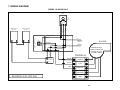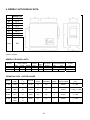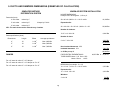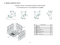
1
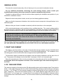
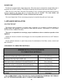
Installation and operating instructions
for Steers furnaces
READ THE MANUAL THOROUGHLY
BEFORE OPERATING THE FURNACE
FURNACE MODELS INCLUDED IN THIS MANUAL
SIERRA 140 WOOD AND COMBINED
15 Kw, 18 Kw, 20 Kw, 25 Kw and UH-Sierra 140
Read these instructions carefully before installing
and operating your furnace.
CONGRATULATIONS!
You have purchased one of the finest wood or combined furnaces
available on the market. We are confident that your furnace will provide
years of comfort and safe operation.
Distributed by
Steers Group Limited
Manufactured by :
STOVE BUILDER INTERNATIONAL INC.
1700, Léon-Harmel, Québec (Québec) G1N 4R9
Tel : (418) 527-3060
Fax : (418) 527-4311
www.sbi-international.com
Please keep this document!
45365
TABLE OF CONTENTS
SECTION A: WOOD OR WOOD/ELECTRIC COMBINED FURNACES.......................................3
INTRODUCTION........................................................................................................................3
1. CHIMNEY AND DRAFT ........................................................................................................3
2. SAFETY RULES ...................................................................................................................3
GENERAL REQUIREMENTS.................................................................................................3
ODOUR FROM THE PAINT ...................................................................................................4
ASH DISPOSAL .....................................................................................................................4
CREOSOTE BUILD-UP AND REMOVAL...............................................................................4
SMOKE DETECTOR ..............................................................................................................5
DOOR GLASS ........................................................................................................................5
GLASS SPECIFICATIONS .....................................................................................................5
ASH DRAWER .......................................................................................................................5
ASH GRATE ...........................................................................................................................5
3. APPLIANCE INSTALLATION.................................................................................................6
UNIT LOCATION ....................................................................................................................6
CLEARANCES TO COMBUSTIBLE MATERIALS..................................................................6
FLUE AND BAROMETRIC DAMPER CONNECTION............................................................7
DAMPER ................................................................................................................................8
COMBUSTION AIR ................................................................................................................8
ELECTRICAL CONNECTION.................................................................................................9
ELECTRIC ELEMENT SIERRA 140 WOOD / ELECTRIC....................................................10
THERMOSTAT .....................................................................................................................11
FAN CONTROL ....................................................................................................................11
4. OPERATING INSTRUCTIONS ............................................................................................11
CONTROL SYSTEM ............................................................................................................11
LIGHTING.............................................................................................................................12
PREHEATING ......................................................................................................................12
HEATING..............................................................................................................................12
EARLY SIGNS OF OVERFIRED FURNACE:.......................................................................13
WOOD AS HEATING FUEL .................................................................................................13
CHIMNEY FIRES..................................................................................................................13
5. MAINTENANCE ...................................................................................................................14
MAINTENANCE OF THE EXCHANGERS ...........................................................................14
CHIMNEY MAINTENANCE ..................................................................................................15
MAINTENANCE OF THE BLOWER MOTOR.......................................................................15
FILTERS ...............................................................................................................................15
DOOR GASKET MAINTENANCE ........................................................................................15
6. REPLACEMENT PARTS .....................................................................................................16
DOOR GLASS ......................................................................................................................16
GASKET ...............................................................................................................................16
7. WIRING DIAGRAM ..............................................................................................................17
SIERRA 140 WOOD ONLY ..................................................................................................17
8. SIERRA 140 TECHNICAL DATA .........................................................................................18
GENERAL TECHNICAL DATA.............................................................................................18
TECHNICAL DATA – ELECTRIC MODE .............................................................................18
1
9. DUCTS AND DAMPERS DIMENSIONS (EXAMPLES OF CALCULATION) .......................19
10. SIERRA 140 BRICKS LAYOUT .........................................................................................20
11. TROUBLE SHOOTING ......................................................................................................21
SECTION B: WOOD/OIL COMBINED FURNACES. ..................................................................22
GENERAL NOTES...................................................................................................................23
1. DRAFT AND CHIMNEY .......................................................................................................23
2. OIL TANK AND PIPING .......................................................................................................23
BURNER PUMP ...................................................................................................................24
3. APPLIANCE INSTALLATION...............................................................................................24
LOCATING THE UNIT..........................................................................................................24
CLEARANCES TO COMBUSTIBLE MATERIALS................................................................24
POSITIONING THE APPLIANCE .........................................................................................26
PIPE CONNECTOR AND DAMPER.....................................................................................26
COMBUSTION AIR ..............................................................................................................27
ELECTRIC COMPONENTS INSTALLATION .......................................................................28
ELECTRICAL WIRING .........................................................................................................29
THERMOSTAT .....................................................................................................................29
FAN CONTROL ....................................................................................................................29
COMBUSTION SAFETY CONTROL ....................................................................................30
COMBUSTION ADJUSTMENT AND VERIFICATION..........................................................30
ELECTRODES SETTING.....................................................................................................31
4- APPLIANCE START-UP ......................................................................................................32
5- PROLONGED CLOSING .....................................................................................................32
6- MAINTENANCE ...................................................................................................................32
SERVICE ..............................................................................................................................32
MAINTENANCE....................................................................................................................33
FILTERS ...............................................................................................................................33
7- ELECTRICAL DIAGRAMS ...................................................................................................34
8- TECHNICAL DATA ..............................................................................................................35
STEERS LIMITED LIFETIME WARRANTY .............................................................................36
2
SECTION A: WOOD OR WOOD/ELECTRIC COMBINED FURNACES.
INTRODUCTION
Take note that this furnace operates like an EPA wood burning stove. This applies to the lighting, the embers and
the minimum combustion air intake which depends on the type and the grade of the combustible.
This model line is certified as meeting the emissions limits in 40 C.F.R. part 60, section 60.532 (B) per EPA
methods 28 and 5G-3, February 1988.
Average emissions rate: 6.56 g/hr
Average heating efficiency: 71.43%
To optimize the efficiency of your furnace, here are few advices you should follow when installing or operating
your Sierra 140.
Respect the local codes (when in doubt, consult your local dealer).
Make sure your furnace is installed according to the instructions on the certification plate.
All controls adjustments must be performed by a qualified technician. The controls settings and the blower speed
must conform to the recommendations of the National Warm Air Heating and Air Conditioning Association and
respect the recommended static pressure ranges in the warm air bonnet of the furnace (see General Technical data
static pressure).
1. CHIMNEY AND DRAFT
This furnace must be connected to a chimney certified for use with wood burning heating appliances; a 7 inch
chimney and connector are recommended for the Sierra 140 (see 3.Appliance installation, paragraph C).
If draft exceed –0.06 in. W.C a barometric damper should be installed on the smoke pipe.
Never install a manual damper.
The barometric control must be adjusted so that the maximum draft measured at the furnace outlet does not
exceed -0.06 in. w.c. Please note that a draft exceeding -0.06 in. w.c. will reduce the efficiency and could produce
an uncontrollable fire. On the other hand, the minimum draft required is -0.04 in. w.c. in the evacuation pipe
on the wood side, no matter what type of furnace (WOOD, WOOD / ELECTRIC OR WOOD / OIL).
2. SAFETY RULES
GENERAL REQUIREMENTS
Make sure the chimney outlet and the pipes are clean and in good condition.
Do not use chemical products or liquids to light the fire.
Do not burn wood coated with paint, glue or chemical products.
Do not burn wastes or flammable liquids such as gasoline, naphtha or motor oil.
Do not install an automatic feeder on this furnace.
Do not store wood in the vicinity of the furnace. Respect the required clearances between combustible materials
and the source of heat.
3
WARNING
-THE ASH DRAWER AND EXCHANGERS ACCESS PANEL GET VERY HOT.
-DO NOT MANIPULATE WITH BARE HANDS.
ODOUR FROM THE PAINT
It is normal that smoke and odours emanate from the unit when you first light it. It is recommended to burn it at
high rate and ventilate the building until the odours resorb.
ASH DISPOSAL
Ashes must be placed in a metal container with a tight fitting lid. The container should be stored outdoors, well
away from combustible materials. If the ashes are meant to be buried in soil, wait until all cinders have thoroughly
cooled before burying.
CREOSOTE BUILD-UP AND REMOVAL
When wood is burned slowly, it produces tar and other organic vapours which, when combined with moisture,
form creosote. The creosote vapours condensate in a relatively cool chimney flue. As a result, creosote residues
accumulate on the flue lining.
N.B.: To minimize the frequency of the chimney cleaning, buy your firewood at least one year before using it. Store
it in a dry place in order to obtain the minimum moisture rate and optimize the efficiency. Do not store wood or
combustible materials within the installation minimum clearances or the space required to reload the appliance and
remove the ashes.
When ignited, creosote produces an extremely hot fire inside the chimney.
To avoid chimney fires, it is important to do the turnover of wood. Inspect the chimney system at regular intervals
to determine a cleaning cycle. A weekly cleaning might be required during mild temperature periods while a monthly
cleaning should be sufficient during colder periods.
If a significant layer of creosote has accumulated, it must be removed immediately to eliminate the risk of
chimney fire.
Remember that a small hot fire is preferable to a large smouldering one to prevent creosote build-ups within the
system. Prepare an emergency procedure in case of a chimney fire.
It’s recommended to clean the heat exchangers thoroughly at the end of season in order to prevent
corrosion.
4
SMOKE DETECTOR
We highly recommend the use of a smoke detector. It must be installed at least 15 feet (4,57 m) from the
appliance in order to prevent undue triggering of the detector when reloading.
DOOR GLASS
To maintain a clean and safe installation, do not build your fire too close to the glass or allow the fire logs to lean
on the glass.
Do not operate your furnace at too low a setting. Keep the air inlet opened long enough during the fire start-up to
prevent the fire from smouldering, which could stain the glass.
An intense fire will help keeping the glass clean. However, in the event that your glass gets stained, which should
normally not occur, you will have to clean it using a wet cloth and an oven cleaner. Clean the glass ONLY when the
unit has cooled down. Do not use abrasive cleanser. Wood stove glass cleaners are available on the market and
their efficiency makes no doubt.
WARNING: Avoid knocking or scratching the glass which could crack or break.
GLASS SPECIFICATIONS
The glass is made of Pyroceram type of glass, 3/16” – (5 mm) thick.
Do not operate your furnace with a broken glass, as this could seriously damage your furnace.
You can purchase a replacement glass from your STEERS dealer.
ASH DRAWER
Your furnace is equipped with an ash drawer to collect ashes produced by the combustion of wood. This drawer
must not be left open during combustion as this may cause over firing and serious damages to the furnace.
The drawer must be cleaned regularly.
It is important that the door and the ash drawer be kept closed while the appliance is in use.
Maintain all gaskets in good condition; in case of deterioration, contact your dealer for replacement
gasket.
ASH GRATE
You must replace the ash grate if it is damaged and a replacement may be obtained from your dealer. The steel
plate on the ash grid is meant to optimize the heat inside the combustion chamber and should only be removed to
empty the ashes.
5
3. APPLIANCE INSTALLATION
UNIT LOCATION
The furnace must be installed where outside air supply is sufficient for proper combustion. In airtight houses, it
might be necessary to install an outside air inlet (see details in: COMBUSTION AIR).
The furnace must be positioned so that the connector is as short as possible; minimize the use of 90o elbows.
The owner must ensure a proper installation to allow a safe operation of the appliance.
CLEARANCES TO COMBUSTIBLE MATERIALS
N.B. This appliance must be installed according to the instructions on the unit’s certification plate.
MINIMUM CLEARANCES TO COMBUSTIBLE MATERIALS FOR SIERRA 140
FURNACE
N.B. THE SIZE OF THE AIR RETURN CONDUITS SHOULD BE AT LEAST EQUAL TO THE SIZE OF
THE COLD AIR PLENUM OPENING.
6
FLUE AND BAROMETRIC DAMPER CONNECTION
Before connecting the stove pipe, make sure you have removed the accessories
from the flue pipe as the scraper, shovel and the poker.
The flue outlet on the Sierra 140 furnace is 6” in diameter and the wood only or wood/electric models may be
installed with a 6” chimney approved for use with wood burning heating appliances (2100°F). However, we
recommend the use of a 7” chimney to allow the retrofit to wood/oil configuration, if desired, without changing the
chimney; in that case, a 6” to 7” reducer must be installed at the flue outlet of the furnace. If the draft exceed -0.06
w.c., a barometric control must installed.(see Damper) Never install a manual damper.
UH-SIERRA 140
PIPE
REDUCER
DIAMETER 7 "
For a proper installation, follow the advices below:
1. All the evacuation pipe joints must be secured with three screws.
Make sure that each screw goes through the inner walls of both connectors (male and female).
See pictures below showing a male-female coupling.
PROPER INSTALLATION
IMPROPER INSTALLATION
2. A minimum rise of 1/4 inch per horizontal foot must be respected.
7
CAUSE RESTRICTION
DAMPER
If the draft exceeds -0.06 w.c., a barometric damper must installed. The barometric damper must be adjusted so
that the maximum draft measured at the furnace outlet is limited to -0.06 in. w.c. Please note that a draft higher than
-0.06 w.c. will reduce efficiency and could result in an uncontrollable fire. On the other hand, the minimum draft
to be respected is -0.04 in. w.c. in the evacuation pipe on the solid fuel side, no matter what type of furnace
(WOOD, WOOD / ELECTRIC OR WOOD / OIL).
COMBUSTION AIR
When the furnace and the chimney are completely cold, it might be necessary to provide fresh air by opening a door
or a window for a few minutes while lighting the fire.
Take note that a house constructed or renovated in order to be airtight is liable to lack fresh air necessary for the
proper combustion of a flame producing heating appliance.
In such a case, when starting up the fire, do not operate appliances which evacuate air outside the house such
as:
-
Range hood
-
Air exchanger
-
Clothes dryer
-
Bathroom fan
-
Ventilated central vacuum system
NOTE:
It is recommended to install an outside air inlet of minimum 4” diameter in the room where the heating appliance is
installed (see drawing below). It is preferable to choose a wall which is not exposed to dominant winds, depending
on the conditions surrounding your house.
Insulated conduit full length
Fresh air
intake
Free air
entry
Exterior
wall
N.B.
The owner of the furnace is responsible for the room salubrity in case of negative pressure or
temporary negative pressure.
8
ELECTRICAL CONNECTION
The following instructions do not supersede the local code.
SIERRA 140-WOOD ONLY
On the wood Sierra 140, the fan limit control is installed with the support provided, on the left side of the
appliance, (four holes are pre-drilled on the edge of the furnace, use the two that are closer to the front of the
furnace), and connected to the electrical box along with the transformer. Install the damper motor on the right side
of the facade, above the door (use the pre-drilled holes). The chain that links the air inlet damper to the motor must
have a play of 1/8 in. When there is no call for heat, the air inlet damper must be completely closed and the chain
must be hooked to the servo-motor at the “8 o’clock” position. *
HOLES TO
SECURE FAN
LIMIT BRACKET
SERVOMOTOR
WARNING: USE WIRING SUITABLE FOR 75O C
9
SIERRA 140 WOOD/ELECTRIC
The high limit control is a manual reset thermostatic captor that is located inside the electric unit (see WIRING
DIAGRAMS). The electric unit must be connected as shown on the diagram. Install the wood fan limit control on
the support provided, at the determined location. The connections must conform to the diagram.
Install the damper with the bracket included at the right location. Install the damper motor on the right side of the
façade above the door (use the pre-drilled holes). The chain that links the air inlet damper to the motor must have a
play of 1/8 in. When there is no call for heat, the air inlet damper must be completely closed and the chain must be
affixed to the damper motor at the “8 o’clock” position. *
WARNING: USE WIRING SUITABLE FOR 75O C
• * (With all reserves on the minimum combustion air to be increased depending on the type and quality of the
combustible).
ELECTRIC ELEMENT SIERRA 140 WOOD / ELECTRIC
The WOOD / ELECTRIC combined model uses two thermostats: one thermostat controls the electric heating, the
other one controls the wood heating. With this system, the electric heating has priority over the wood heating.
When the thermostat activates the electric heating, the air inlet damper closes down (if opened), the blower starts
and the electric elements are successively activated per block of 5 kW. The system may be equipped with an
outdoor sensor (not included) which will allow the last block of elements (5 kW) to start up only when the outside
temperature is cold enough. This will reduce the power of the systems by 5 kW during mild temperature for more
comfort and economy.
When the call for electric heating is satisfied, the wood system will take over if the starting point of the wood
system thermostat is superior to that of the electric system so, in normal bi-energy use, you should set the wood
system thermostat 2o to 3° C. higher than the electric system thermostat; the bigger the gap, the more the wood
heating will contribute to the overall heating needs.
Take note that this furnace is equipped with a four speed blower motor. Aside from low speed, you may select
medium-low, medium-high or high speed.
If the temperature of the electric unit exceeds the high limit , the thermostatic captor will disengage the elements.
To reactivate, press the red “manual reset” button on the thermostatic captor ( L-170 Thermodisc) after finding and
fixing the problem that has caused the unit to overheat (static pressure too high, fan breakdown, etc.)
INSIDE VIEW OF THE
ELECTRIC ELEMENT
Red button
manual reset
L-170 Thermodisc
RESET
10
OUTSIDE VIEW OF THE ELECTRIC ELEMENT
THERMOSTAT
The thermostat must be installed on an inside wall in a location where it is not likely to be affected by the draft
coming from an air outlet. It must be installed at a minimum of 55 inches above the floor.
N.B. Both thermostats used on the combined wood / electric model should be installed at same height.
FAN CONTROL
The fan limit control setting may vary depending on the type of installation. The temperature setting “out of
service” is preset at 110o F, the temperature setting “in service” at 150o F. and the high limit at 250° F at the factory.
These settings should provide a proper operation for most installations.
It is preferable, for a prolonged operation of the blower, that the setting “out of service” be low enough. But a
setting “out of service” too low will cause undesirable cold air circulation. To modify the settings, simply move the
tabs to the desired position on the temperature dial of the fan limit control.
The adjustment of all controls must be performed by a qualified technician. The controls setting and the blower
speed must conform to the recommendations of the “Warm Air Heating and Air Conditioning National Association”.
For continuous operation of the blower, use the switch located below the fan limit control or on the electric unit which
controls the low speed either at the “on” position or the “off” position.
It is not recommended to let the blower run on continuous mode when heating with wood since the wood furnace
must reach a certain temperature before the blower starts in order to operate efficiently.
4. OPERATING INSTRUCTIONS
CONTROL SYSTEM
On the wood furnaces only, the thermostat controls the air inlet damper. When the thermostat calls for heat, the
damper opens and the fire stirs up. When the furnace gets hot enough, the combined limit control activates the
blower motor at the speed selected for wood heating.
11
The chain that links the air inlet damper to the motor must have a play of 1/8 inch. When there is no call for heat,
the air inlet damper must be completely closed and the chain must be affixed to the damper motor at the“8 o’clock”
position. *
* (With all reserve on the minimum air to be increased depending on the type and quality of the combustible).
LIGHTING
1. Open the door
Note: In the case that there is a bed of coals in the bottom of the furnace, go to Pre-heating.
2. Remove the steel plate on the ash grid and dump the ashes in the ash drawer.
3. Put the steel plate back in place, making sure it is properly seated. The steel plate on the ash grid is intended to
optimize the heat retention into the combustion chamber.
4. Place one or two dry kindlings at the front of the furnace.
5. Place newspaper strips on top of the kindlings.
6. Cover the newspaper with more kindlings and small pieces of dry wood.
7. Add newspaper strips, then light the fire a low as possible and leave the door 1/2" (13 mm) opened. If you fail
lighting the fire, you might experience a back draft through the air inlets.
PREHEATING
1. Once the kindling is well ignited or the coals revived, put 2 or 3 fire logs in such a way that the flames can
interlace between the logs then close the door. It is important to respect these loading sequences so that the
wood will burn from the front to the back of the furnace.
2. Wait 15 to 20 minutes, then proceed with loading the furnace.
HEATING
1. When loading the furnace, lower the kindled pieces of wood and place them at the center of the combustion
chamber before adding new logs.
2. Do not overload. Air must circulate freely in the upper part of the combustion chamber in order to obtain an
efficient operation of the appliance. Please note that a small hot fire will produce much less residues than a large
smouldering one.
IMPORTANT: DURING THE HEATING PROCESS, REMOVE THE ASHES AND WOOD THAT COULD
OBSTRUCT THE 1/4" (6.4 mm) HOLE LOCATED BELOW THE DOOR INSIDE THE FURNACE.
PROCEDURE TO OPEN THE LOADING DOOR
TO MINIMIZE THE RISK OF SMOKE SPILLAGE, OPEN THE DOOR 1”
AND WAIT ABOUT 10 SECONDS BEFORE OPENING COMPLETELY.
THE PURPOSE IS TO STABILIZE THE PRESSURE INSIDE THE FURNACE.
Prolonged power failure
At the time of a prolonged power failure, you can still use your furnace. The air intake register remains in closed
position and the furnace functions at the minimal combustion mode. It is very important to ensure you that the holes
located under the loading door inside the furnace are free to ensure a good performance (small holes of ¼”).
12
EARLY SIGNS OF OVERFIRED FURNACE:
1. Roaring fire.
2. Chimney connector is glowing red.
3. Extreme heat coming from the furnace. If this occurs, DO NOT OPEN THE DOOR, shut-off the air inlet opening
completely, and wait until the glow has completely subsided.
ALWAYS KEEP THE DOOR AND THE ASH DRAWER CLOSED
(except for lighting and maintenance).
WOOD AS HEATING FUEL
We recommend that you burn dry hard wood only.
There are two important factors to be considered when choosing a type of wood: the moisture content and the
wood density. Hardwood, such as maple, oak and beech will provide better results because of the high density and
minimal tar produced during combustion. It is highly recommended to use wood that has been dried at least six
months. Do not use coal as heating fuel in this appliance.
Whenever a high rate of smoke is noticed in the room, you must:
1. Open doors and windows.
2. Make sure the furnace door is closed as well as the damper (if necessary, lower the thermostat starting point or
unhook the damper chain and close the barometric draft control manually).
3. When the furnace has cooled down, inspect the chimney to detect obstructions and consult a specialist to
determine the cause of the smoke spillage.
CARBON MONOXYDE IS A LETHAL GAS (ODOURLESS AND COLOURLESS), WHICH YOU MUST
BEWARE OF.
CHIMNEY FIRES
This might occur when the fire gets extremely hot. Burning cardboard, branches or small pieces of wood can
ignite the creosote residue accumulated in the evacuation flue system. The usual signs are:
1. Rumbling
2. The flue gets extremely hot
3. Flames or sparks are coming out of the chimney
In case of a chimney fire, call your local fire department immediately and sprinkle the
roof around the chimney with water.
Make sure that the furnace door is closed as well as the damper (if necessary, lower the thermostat starting point
or release the chain from the damper and CLOSE the barometric draft control manually).
If the fire gets uncontrollable due to an improper use or because the draft is too strong, follow the same procedure
as in a chimney fire except that you will have to OPEN the barometric draft control manually.
LOCAL FIRE DEPARTMENT.
Phone number: ___________________________________
13
5. MAINTENANCE
MAINTENANCE OF THE EXCHANGERS
The evacuation pipe and the exchangers should be inspected regularly during the burning season. Easy access
is provided (without the use of tools): simply unscrew the wing nut on the exchangers access door.
See pictures below.
Wing nut
Insulation
pad
Exchangers cover
Before cleaning the three exchanger pipes, move the upper plate of the combustion chamber forward (see
drawing on next page). Using the scraper, clean the three exchanger pipes. The accumulated dirt in the lateral
exchangers will fall into the combustion chamber; the dirt in the central exchanger will have to be removed from the
front or the back of the furnace. Then, ensure that the upper plate is free of ashes. Do not forget to push the
upper plate back to it’s original position. Finally, close the exchanger access door.
SIERRA 140
SECTION VIEW
14
CHIMNEY MAINTENANCE
The most efficient method to sweep the chimney is using a hard brush. Brush downwards so soot and creosote
residues will come off the inner surface and fall at the bottom of the chimney where they can be removed easily.
The chimney must be checked regularly and if creosote has accumulated, it must be removed without delay.
Cleaning on a monthly basis should be sufficient during the coldest months.
Smoke flue inspection
-
The smoke flue should be inspected regularly during the heating season.
-
If possible, the smoke flue should be dismantled and cleaned.
-
The flue should be inspected for possible damage.
-
If it is in good condition, put the flue back in place; otherwise, it must be replaced.
-
Use only wood as a combustible.
-
Seasoned hard wood logs 18” to 22” long are recommended as combustible.
MAINTENANCE OF THE BLOWER MOTOR
The two motor bearings must be lubricated once a year using non detergent SAE 20 oil.
DO NOT OVERLUBRICATE
FILTERS
The furnace must not be operated without filters. In order to efficiently and safely operate a slow combustion
heating system , you have to ensure a regular maintenance. This means that the chimney, the joints and the flue
must be kept in good condition and the air filters must be replaced regularly; use the same size and same type as
the original filters.
Filters dimensions
Sierra 140: 12” x 24” filters, part #21039
DOOR GASKET MAINTENANCE
It is important to maintain the door gasket in good condition. After a while, the gasket might sag; a door
adjustment may then be required. If the door adjustment is not sufficient, replace the door gasket.(see 6-Gasket)
15
Door adjustment procedure:
1. Unscrew completely the locking pin (see picture below).
Locking pin
2. To increase the pressure of the door on the gasket, turn the handle counter clockwise; to decrease the pressure
of the door on the gasket, turn the handle clockwise until desired pressure is attained.
3. Then screw back the locking pin about 1/4” deep and make sure you lock it in place with the nut.
6. REPLACEMENT PARTS
Your STEERS furnace is designed to burn clean and requires little maintenance. It’s recommended to conduct a
visual inspection at least once a month to uncover any damage to the unit. Any defect must be repaired without
delay using genuine STEERS replacement parts.
DOOR GLASS
•
•
•
•
•
Inspect the glass regularly to detect any glass failure. If you find any defect, stop using the furnace
immediately. Never operate a wood furnace with a broken glass.
If you have to change your door glass, you must use Pyroceram 3/16” (5mm) thick. Use genuine parts sold
by a STEERS authorized dealer.
To replace the glass, remove the screws that hold the glass retainers in place. Removed these retainers
and replace the defective glass; the glass gasket should be replace at the same time. To put back in place,
reverse the procedure.
Do not used abrasive cleanser. Special cleansers for wood stoves glass are available in any good hardware
store.
Clean glass ONLY when the unit has cooled down.
GASKET
We recommend to replace gasket that seals the door once a year, in order to maintain a good control of the
combustion for maximum efficiency and security. To replace your door gasket, remove the old gasket and glue.
Clean the surface thoroughly, apply glue sold for that particular use, and put the new gasket onto the door. Wait for
at least 2 hours before lighting your furnace.
16
7. WIRING DIAGRAM
SIERRA 140 WOOD ONLY
HONEYWELL
L6064
FAN
LIMIT
LINE
LOAD
ON 150°F
OFF 110°F
LIMIT 250°F
BLACK TRANSFO
SERVO-MOTOR
24 V.A.C.
BLUE
THERMOSTAT
24 V.A.C.
RED
LOW HIGH LINE
BLUE
L1
BLACK
120 V.A.C.
BLACK
ON
1
2
3
BLOWER
WHITE
L2
OFF
4 SPEED MOTOR
DIRECT-DRIVE OR
2 SPEED MOTOR
G-12 BELT-DRIVE
WHITE
BLACK
SUMMER SWITCH
JUNCTION BOX
120 V.A.C.
TERMINAL
WHITE
TRANSFORMER
24 V.A.C.
BLACK
RED
COMMON
LOW
MED LOW
MED HIGH
REVISION JULY 6TH 2006
HIGH
20
8. SIERRA 140 TECHNICAL DATA
SIERRA 140
A
B
C
D
E
F
G
47”
25 ½”
47 ¼”
15 ⅞”
28”
24 ½”
TUYAU
44”
* 7”
POIDS
560
* Reducer required
GENERAL TECHNICAL DATA
MODEL
DIRECT DRIVE
FAN
MOTOR
OUTPUT
SPEED
TEMP
VAR.
BTU INPUT
O
(CFM)
( F)
(WOOD)
STATIC PRESSURE
MIN.
FILTER
MAX.
(2)
0,6
12” x 24” X 1”
H2O
SIERRA 140
DD-10
1/3
4
1300
78
140000
0,2
BTU/HR
AMPERES
TOTAL
BREAKER
REQUIRED
FEEDER
GAUGE
VOLTAGE
SINGLE PHASE
ELEMENTS
QTY
51195
75
100
4
120/240
3 – 5 KW
TECHNICAL DATA – ELECTRIC MODE
15 KW
OUTPUT
(CFM)
950
1300
TEMP. VAR.
(O F)
50
36
18 KW
950
1300
60
44
61434
87
125
4
120/240
2 – 5 KW, 2 – 4 KW
20 KW
950
1300
67
49
68260
95
125
3
120/240
4 – 5 KW
950
1300
1800
83
61
44
85325
115
150
2
120/240
5 – 5 KW
MODEL
25 KW
WOOD
15
120
18
9. DUCTS AND DAMPERS DIMENSIONS (EXAMPLES OF CALCULATION)
WARM AIR SYSTEM INSTALLATION
SIMPLIFIED METHOD
DISTRIBUTION SYSTEM
HOUSE DIMENSIONS
Example: 28 x 40 bungalow: 1,120 sq. ft.
Ducts size (heat)
4 inch outlet
reduce by 1”
5 inch outlet
reduce by 2”
6 inch outlet
reduce by 3”
28 x 40 x 8: 8,960 cu. ft. x 1.8 Ch. air/hr:
Always by 8” thick
16,128 Btu
Exposed walls:
40 + 40 + 28 + 28: 136 x 8: 1,088 cu. ft. x 22:
N.B.: The main duct must be reduced every 2 outlets.
23,936 Btu
Number of windows:
12 of 3 x 4: 144 x 60:
Ducts specifications (heat)
Dimensions
8,640 Btu
Number of doors:
Length
Elbow
Average equivalence
4”
10’
1 x 90o
Max 4,000 Btu
5”
10’
1 x 90o
Max 6,000 Btu
6”
10’
1 x 90o
Max 7,000 Btu
2 x 3 x 7: 42 x 100:
4,200 Btu
52,904 Btu
Non-insulated basement: 25%
Insulated basement: 15%
7,906 Btu
or 54 Btu per sq. ft.
60,840 Btu
FOR ELECTRIC ELEMENTS 80%:
DAMPER
48,672 Btu or 14,28 kW
TO BE ADDED:House 1 1/2 floor = 25%
House 2 floors
= 40%
For a 4” warm air outlet: 2” x 10” damper
For a 5” warm air outlet: 2” x 12” damper or 4” x 10”
BEDROOM (for example: 12 x 12)
For a 6” warm air outlet: 2” x 14” damper or 4” x 12”
12 x 12 x 8: 1,152 cu. ft. x 1.8 Ch. air/hr:
2,074 Btu
Exposed walls:
12 + 12 x 8: 192 x 22:
4,224 Btu
Windows:
3 x 4 x 60
720 Btu
7,018 Btu
19
10. SIERRA 140 BRICKS LAYOUT
WARNING: INSTALL THE CERAMIC BLANKET PANEL BEFORE
PUTTING BRICKS UP IN THE COMBUSTION CHAMBER
1"
42
9"
Item
5
5
5
7
5
3
5
5
5
5
5
5
3
5
4
5
5
2
8
3
3
3
6
6
1"
3
5
4
5
3
5
8
5
5
1
9"
1"
42
5
5
7
8
4"
8
8
9"
5"
18
4
3"
4
5"
8
1"
32
5"
316
1"
42
6
1"
14
3
5
20
DESCRIPTION
QTY
1
ASHGRATE
1
2
BRICK 4 X 8
1
3
BRICK 4 X 9
8
4
BRICK 4X9 SPECIAL
2
5
BRICK 4.5 X 9
21
6
½ BRICK 4.5X9 SPECIAL
2
7
BRICK 1.25 X 9
1
8
BRICK 4.5X9 SPECIAL
4
11. TROUBLE SHOOTING
PROBLEM
CAUSES
SOLUTIONS
Heating inefficient during the first
combustions. Lack of draft.
Improper adjustment of the
barometric damper (opened too
wide). Chimney flue restriction
(too long. 90o elbows)
Adjust the damper, minimize the
chimney length and use 45o
elbows.
Furnace heats well, warm air
plenum is very hot by there is not
much heat coming out in the
room.
Improper installation of the ducts,
little static pressure, unbalanced
system (too many warm air
outlets and not enough cold air
inlets).
Reinstall the ducts correctly.
Respect the minimum static
pressure of 0.20 in. w.c.
Furnace consumes a lot of wood.
The thermostat which controls
the damper is continuously
activated and is too close to a
source of cold. Damper not
properly adjusted. House not
insulated enough. Ash drawer is
not tightly closed. Furnace too
small for the surface to be
heated. Unbalanced ventilation
system, very little heat where the
thermostat is located.
Relocate the thermostat. Adjust
the chain that links the damper to
the servo-motor. Rebalance the
ventilation system in order to
increase the air flow in the room
where the thermostat is located.
Fan start-up is too slow.
Fan “ON” setting too high.
Return air is too cold
(temperature lower than 65
degrees). Limit control not well
located in the warm air plenum.
Lower the temperature starting
point. Usually, the limit control is
set at 150 degrees, we can under
certain conditions, reduce this
temperature. Reduce the fresh air
flow. Relocate the limit control.
A lot of creosote, moderate heat
output.
Wet wood, lack of draft.
Barometric damper not properly
adjusted. Sooted up chimney.
Use dry wood. Adjust the
barometric damper. Clean the
chimney flue and the furnace
exchangers.
Furnace heats a lot but the warm
air plenum does not get hot.
Wet wood or low grade wood.
Too much cold air return for the
hot air ducts. Unbalanced
ventilation system.
Use dry wood. Reinstall the
ventilation system correctly.
IMPORTANT NOTE
FOR, INSTALLATION OF A CENTRAL HEATING VENTILATION SYSTEM, IT IS
HIGHLY RECOMMENDED TO CONSULT A HEATING SYSTEM VENTILATION
SPECIALIST
21
SECTION B: WOOD/OIL COMBINED FURNACES.
INSTALLATION
AND OPERATION INSTRUCTIONS
FOR UH-SIERRA 140 WOOD/OIL
COMBINED FURNACES
READ THIS MANUAL THOROUGHLY
BEFORE OPERATING THE FURNACE
CERTIFIED BY OMNI ACCORDING TO CAN/CSA B366.1-M91, UL391 3e ed. 1995,
rev. 1999 & CAN/CSA B212-93 (JUNE 2000)
CAUTION
CAUTION
EXPLOSION OR FIRE HAZARD.
FOR YOUR SAFETY: DO NOT
STORE OR USE GASOLINE OR
ANY FLAMMABLE LIQUIDS OR
VAPORS IN THE VICINITY OF
THIS HEATING UNIT.
DO NOT ATTEMPT TO LIGHT THE
BURNER WHEN EXCESS OIL HAS
ACCUMULATED, WHEN THE
APPLIANCE IS FULL OF VAPOR OR
WHEN THE COMBUSTION
CHAMBER IS VERY HOT.
DO NOT BURN WASTES OR PAPER IN THE APPLIANCE.
DO NOT LEAVE PAPER OR ANY COMBUSTIBLE MATERIAL
AROUND THE APPLIANCE.
PLEASE SAVE THESE DOCUMENTS!
22
GENERAL NOTES
This instruction manual treats mainly of the oil burning unit of your wood/oil combination furnace.
For any additional information concerning the wood burning furnace, please consult your
installation and operation instructions manual for wood and wood/electricity furnaces.
To obtain the optimal efficiency, follow the advices below regarding the installation and operation of your
WOOD/OIL combination furnace.
Respect the local codes (when in doubt, consult your local heating appliances dealer).
Make sure that the clearances indicated on the instruction manual correspond to the specifications in the
certification plate.
Make sure that your furnace is installed in conformity with the instructions on the name plate.
All the controls adjustments must be performed by a qualified technician. The controls settings and the
fan speed must be in compliance with the recommendations of the Warm Air Heating and Air Conditioning
National Association and must respect the static pressure ranges in the warm air plenum of the furnace.
THE INSTALLATION OF THE WOOD/OIL COMBINATION FURNACE MUST BE
DONE IN ACCORDANCE WITH THE RULES OF THE AUTHORITIES HAVING
JURISDICTION AND THE CAN/CSA B-139 M-91 STANDARD FOR OIL BURNING
HEATING APPLIANCES.
The oil burning furnaces are not approved for use with combustible heavier than No.2 oil (furnace oil). DO
NOT USE GASOLINE, TRANSMISSION OIL OR OTHER TYPE OF OIL CONTAINING GASOLINE.
1. DRAFT AND CHIMNEY
The chimney must be conform to the rules of the authorities having jurisdiction and the CAN/CSA B139
M-91 & NFPA 31 standard regarding installation of oil burning heating appliances. The installation of the
connecting pipes to the oil unit must be done and approved by a qualified pipe fitter.
The barometric damper provided with the appliance must be properly installed on the flue pipe of the oil
unit. The purpose of the damper is to limit the draft, if necessary, in the oil unit evacuation pipe.
Since the evacuation pipe of the oil unit is connected to the evacuation pipe of the wood burning furnace,
the minimum draft to be respected at all times in the evacuation pipe of the wood burning side is 0.04” W.C.
2. OIL TANK AND PIPING
The maximum capacity of the tank must be 200 gallons and the tank must be located at least 7 feet from the
burner. Local codes will govern the size of the air inlets and filling openings as well as the type of plugs to
be used. 1 1/4" IPS and 2" IPS are usually accepted as minimum dimensions for the air intake pipes and fill
pipes, respectively. The oil line to the burner must be a 3/8" outside diameter copper tubing for runs up to
50 feet and ½” o.d. for longer runs. A manual shut-off valve and an oil filter shall follow in sequence on the
oil line between the oil tank and the burner. The oil line must be buried or protected adequately to avoid any
damage.
23
BURNER PUMP
The burner is equipped with a single stage pump. When the pump is connected to a single feeder pipe, a
maximum rise of 8 feet is allowed. This height is measured from the tank outlet level to the burner inlet.
When the rise is more than 8 feet and not exceeding 10 feet, a by-pass plug (provided with the burner)
must be inserted in the pump and an oil return pipe must be installed. For more details, see
“INSTALLATION INFORMATIONS”, Part No. 21844 on the burner pump.
If the rise is higher than 10 feet, a two stage pump may be required along with an oil return pipe.
3. APPLIANCE INSTALLATION
LOCATING THE UNIT
The furnace must be installed in a location where combustion air is available in sufficient quantity. In
airtight houses, the installation of an outside air intake might be required. (See details in 3- APPLIANCE
INSTALLATION, COMBUSTION AIR).
The owner is responsible for ensuring a proper installation to allow a salubrious operation of the
appliance.
Position the furnace so that the connecting pipe is as short as possible and limit the use of 90o elbows to
a minimum.
Provide sufficient clearance to permit easy access for maintenance of the filters, motors, controls and
pipe connectors.
CLEARANCES TO COMBUSTIBLE MATERIALS
MINIMUM INSTALLATION CLEARANCES
TO COMBUSTIBLE MATERIALS
WARM AIR PLENUM AND FIRST 6 FEET OF DUCT
6 in.(152 mm)
PLENUM AFTER THE FIRST 6 FEET = B
1 in. (25.4 mm)
REAR (INCLUDING CLEARANCE FOR MAINTENANCE) = A
24 in. (610 mm)
SIDES (INCLUDING CLEARANCE FOR MAINTENANCE)
24 in.(610 mm)
OIL BURNING UNIT FLUE PIPE
9 in.(229 mm)
WOOD BURNING FURNACE FLUE PIPE
18 in.(458 mm)
* FLOOR
0 in.(0 mm)
* ON A COMBUSTIBLE FLOOR, THE USE OF A FLOOR PROTECTION EXCEEDING THE FURNACE
BY 8” AT THE REAR AND SIDES AND 18” IN FRONT IS RECOMMENDED.
24
N.B. These appliances must be installed in conformity with the instructions
on the name plate.
CEILING
CEILING
6' 0''
B
6''
18''
45° ELBOW
HOT AIR PLENUM
MIN. 12''
STATIC PRESSURE CHECK
POINT MIN. 0.20 " W.C.
WALL
OIL UNIT
SMOKE
PIPE
9''
WALL
WALL
18''
24''
24''
A= 29'' ALL MODELS EXEPT CADDY = 24''
B= 2'' ALL MODELS EXEPT CADDY = 1''
N.B. FOR AIR RETURN, RESPECT THE OPENING SURFACE OF THE OUTSIDE AIR PLENUM OF THE FURNACE.POSITIONING
THE APPLIANCE
25
POSITIONING THE APPLIANCE
For a safe and quiet operation, the furnace must be levelled in both directions. Give each “U”
shape track, an equal support so that the weight is evenly distributed.
PIPE CONNECTOR AND DAMPER
The pipe connecting the furnace to the chimney must be as short as possible. The use of 45o elbows is highly
recommended for a better evacuation of the smoke in the wood burning furnace. The barometric damper provided with
the appliance must be installed in the oil unit evacuation pipe, approximately 24" from the unit flue outlet of the unit.
TYPE OF FURNACE
(UH) OIL BURNING
UNIT FLUE
PIPE DIAMETER
STEERS/ UH-SIERRA 140
5”
FOR STEERS/ UH-SIERRA 140
FIGURE #1
WALL
ELBOW 45°
Ø7"
T CONNECTOR
MINIMUM DRAUGHT IN
WOOD FLUE PIPE
0.04" W.C.
REDUCER 7" TO 6"
BAROMETRIC DAMPER 5"
DRAFT 0.02" W.C. TO 0.04" W.C.
VERIFICATION HOLE
FOR OIL COMBUSTION
FURNACE TYPE
FIGURE #2
CADDY
*REQUIRE A FLUE PIPE REDUCER
CEILING
Ø7"
MINIMUM DRAFT IN
WOOD FLUE PIPE
0.04" W.C.
REDUCER 7" TO 6"
BAROMETRIC DAMPER 5"
DRAFT 0.02" W.C. TO 0.04" W.C.
VERIFICATION HOLE
FOR OIL COMBUSTION
18"
26
CHIMNEY PIPE
DIAMETER
*7"
COMBUSTION AIR
Take note that an airtight house is liable to lack the fresh air needed for proper combustion, specially if
you are using appliances that evacuate air from the house, such as:
-
Range hood
Air exchanger
Clothes dryer
Bathroom fan
Central vacuum cleaning system
In that case, it is recommended to install a 4” fresh air inlet in the room or next to the room where the
heating appliance is located (see drawing below); choose a wall which is not exposed to dominant winds,
depending on the conditions surrounding your house.
INSULATED PIPE
AIR
SUPPLY
AIR INLET
EXTERIOR
WALL
N.B. The owner is responsible for the salubrity of the premises in case of negative pressure or
temporary negative pressure.
27
ELECTRIC COMPONENTS INSTALLATION
All the wires joining the electric components must have the proper length. Run the wires connecting the
servo-motor to the relay-transformer away from surfaces that may get hot (see figure #1).
FIGURE #1
SERVO-MOTOR
FAN LIMIT INSTALLATION ON STEERS UH -SIERRA 140 MODELS
The wood fan limit control must be installed with the mounting bracket, in the warm air plenum on the left
hand side of the appliance; four holes are pre-drilled on the edge to match the holes on the mounting
bracket (see fig. #3). Use the front holes on the Sierra 140.
The fan limit control for the oil unit (affixed to the junction box and relay-transformer, see figure #2) must
be installed on the lower left hand side removable panel, near the oil flue outlet; a 1" diameter hole is prepunched to allow the insertion of the fan limit’s sensor).
FIGURE #2
RELAY
TRANSFORMER
28
FIGURE #3
HOLES FOR
FAN/LIMIT
SUPPORT
ELECTRICAL WIRING
The whole wiring from the distribution panel to the heating unit shall comply with the applicable electrical
standards and local codes. The unit should be connected to its own 15 amp/120VAC electric circuit (see
electrical diagram on page 18).
THERMOSTAT
Both the wood and oil thermostats must be installed side by side on an interior wall, in a location where
they are not affected by the air draft coming from the furnace’s blower; they must be level and at least 55
inches above the floor.
FAN CONTROL
The oil fan limit control settings may vary depending on the type of building and heating installation. The
"fan off” temperature is factory set at 100oF and the "fan on” setting should be positioned as close as
physically possible to the “fan” off” setting; the high limit is set at 250° and these settings should allow
proper operation in most installations.
In order for the blower to run for long enough periods, the "fan off" setting must not be set too high but
too low a setting will result in undesirable cold air circulation. To modify this setting, turn the indicator to the
desired position on the temperature scale of the fan limit control.
All adjustments of the controls must be performed by a qualified technician. The controls settings and the
blower speeds must be set in accordance with the recommendations of the Warm Air Heating and Air
Conditioning National Association.
To obtain a continuous air circulation during summer months, simply use the red manual switch located
on the cover of the junction box which controls the low speed in either “on” or “off” position.
It is not recommended to let the blower run on continuous mode when heating with wood as the wood
furnace must reach a certain temperature before the blower starts to perform adequately.
29
COMBUSTION SAFETY CONTROL
The AFG type oil burner is equipped with an electronic control (# R7184B1032) including a pre-purge
function and a new more durable drive motor.
PRE-PURGE
When there is a call for heat, the burner’s fan will run for 15 seconds before the actual ignition takes place
to vent the combustion chamber and generate a proper draft. This will result in a smoother ignition of the oil
burner.
SAFE OPERATION
If the flame goes out while the burner is running, the CAD cell will detect it; the control will then switch to
the "RECYCLE" mode and cut the fuel supply to the burner for 60 seconds. After this delay, the control
goes back to "IGNITION" mode. If the flame goes out 3 times in a row, the control will switch to the
"LOCKOUT" mode to prevent a continuous cycling of the ignition process, which would cause a premature
sooting of the combustion chamber and smoke pipe. To deactivate the “LOCKOUT” mode, press and hold
the reset button of the control for 30 seconds.
A green diagnostic LED on the control has four states:
-
On = Flame present
Off = No flame
2 seconds On, 2 seconds Off = "Recycle" mode
1/2 second On, 1/2 second Off = "Lockout" mode TEMPORARY SHUT-OFF
By pressing and holding the reset button, the burner will shut-off until the reset button is released. When
the button is released, the control will start over at the beginning of the normal cycle.
FOR ADDITIONAL INFORMATIONS ON OPERATION SEQUENCES OF THE BURNER, CONSULT THE
BURNER INSTRUCTION MANUAL.
COMBUSTION ADJUSTMENT AND VERIFICATION
To enjoy the efficiency of our oil burning units, you must respect the following criterias:
TOOLS REQUIRED:
-
DRAFT GAUGE
SMOKE TESTER
PUMP PRESSURE GAUGE
NOZZLE AND ELECTRODES POSITION TESTER
COMBUSTION TESTER
CHECK LIST:
- SELECTION OF NOZZLE AND HEAD
- NOZZLE / ELECTRODES POSITION IN RELATION TO THE HEAD
- PUMP PRESSURE
- OIL LINE IS BLEED
- LOW FIRING RATE BAFFLE (INSIDE THE BURNER) REQUIRED ON UH-SIERRA 140.
- FAN SPEED
- BAROMETRIC DAMPER POSITION
30
COMBUSTION VERIFICATION PROCEDURE:
A- DRILL A 9/32" DIAMETER HOLE IN THE EVACUATION PIPE APPROXIMATELY 18" FROM THE
OUTLET.
B- CLOSE THE DOOR AND THE AIR INTAKE(S) OF THE WOOD BURNING FURNACE.
C- LIGHT THE BURNER FOR AT LEAST 10 TO 15 MINUTES.
D- OVER THE FIRE DRAUCHT = -0.01 TO -0.02 W.C. (THE DRAFT OVER THE FIRE MUST BE
MEASURED IN THE OPENING IN THE PULSATION TRAP).
E- SMOKE TEST BETWEEN 0 AND 1 ON THE SHELL BACHARACH SCALE (TRACES).
F- DRAFT IN THE CHIMNEY =-0.02 TO -0.04 W.C.
G- PERCENTAGE OF EXCESS AIR = 20 TO 40%, 12% CO2, 4.6% O2.
H- AVERAGE EFFICIENCY OF 80 TO 85 %.
I-
TIGHTEN ALL THE LOCKING SCREWS AFTER COMPLETING THE FINAL ADJUSTMENT.
N.B. – The barometric damper provided with the appliance must be properly installed on the flue pipe of the
oil burning unit. The purpose of the damper is to adjust the draft in the evacuation pipe of the oil
burning unit to the recommended level. Since the evacuation pipe of the oil burning unit is connected
on the evacuation pipe of the wood burning furnace, the minimum draft to be respected is 0.04"
W.C. in the evacuation pipe of the wood burning side, at all time. In fact, a barometric damper
that would be opened too wide could cause an important loss of draft in the evacuation pipe
of the wood burning furnace.
ELECTRODES SETTING
The electrodes must be adjusted by a qualified technician. A proper positioning of the electrodes is
important to get an efficient lighting of the oil.
ELECTRODE SETTING FOR "F" HEAD
5/32"
ELECTRODE
7/16"
1/16"
NOZZLE
31
WARNING:
1. REFER TO THE RATING PLATE FOR THE PUMP PRESSURE AND THE NOZZLE TYPE.
2. REFER TO THE BECKETT INSTRUCTION MANUAL FOR DETAILS ON THE BECKETT PUMP.
3. FOR ELECTRODES SETTING SEE THE BECKETT MANUAL.
4. FOR THE START-UP AND ADJUSTMENT OF THE BURNER SEE THE INSTRUCTION MANUAL OF
THE BURNER.
5. IN CASE OF BURNER FAILURE, REFER TO THE BURNER MANUAL.
4- APPLIANCE START-UP
The start-up must be performed by a qualified technician. Make sure the installation is completed and the
oil tank has been filled up. The oil line must also have been purged.
CAUTION: CLOSE THE BLOWER COMPARTMENT ACCESS
PANEL BEFORE STARTING THE BURNER.
5- PROLONGED CLOSING
A) Cut off the electric circuit
B) Close the oil shut-off valve
NOTE: The shut-off valve must be closed when the appliance is out of service for a prolonged period of
time.
6- MAINTENANCE
At the beginning of heating season, have the complete installation inspected by a qualified service man,
especially the lighting system and the controls.
NOTE: THE UNIT’S MAINTENANCE, REPAIRS AND THE CLEANING OF
THE OIL FILTER MUST BE DONE BY A QUALIFIED TECHNICIAN.
SERVICE
Before calling for service, first check the following:
-
Fuel supply
-
Electric fuses or breakers
-
Thermostat setting
-
Fan limit controls settings
-
The state of the green diagnostic LED on the burner control (see section: APPLIANCE
INSTALLATION, J- COMBUSTION SAFETY CONTROL).
32
MAINTENANCE
WARNING: Turn off electric power supply before servicing the unit.
1. The furnace, the burner and the flue pipe should be cleaned at least once a year.
2. The nozzle should be inspected and replaced if needed.
Handle with care to avoid damaging its surface.
3. The electrodes should be adjusted as indicated in the burner manual.
4. Lubricate the burner motor bearings twice a year.
(2 or 3 drops of SAE 20 non detergent lubricating oil).
5. The oil filter should be replaced annually
Burner no.: _______________ Model: __________ Date of installation: _____________________
Service Telephone no.: Day: ______________________ Night: ___________________________
Dealer’s name and address: _______________________________________________________
TEST REPORT :
CO2 _______% Temp. at stack: ______________ Draft at stack: ________w.c.
Nozzle output: _______________GPH
Smoke colour: ______________________
Inspected by : _______________________________________________________
FILTERS
The furnace should never be operated without filters.
This applies especially to temporary heating during construction period. Operating the furnace without filters
would allow dust and other particles in the air to circulate freely and to penetrate into the fan and motor
carters causing some defects. Clean and replace filters as often as required.
Note : The operation cost is higher when using a dirty filter.
33
7- ELECTRICAL DIAGRAMS
WIRING DIAGRAM FOR STEERS/UH SIERRA 140
(The location of the wood limit is on the plenum and the location of the oil limit is on the panel towards exhaust pipe)
OIL
HONEYWELL
L6064
WOOD
HONEYWELL
L6064
LIMIT
FAN
ON 100°F
OFF 110°F
OFF 100°F
LIMIT 250°F
LIMIT 250°F
LOAD
LINE
LOAD
LOW HIGH LINE
BLACK
BLACK
BLUE
BLUE
SERVO
MOTOR
BLACK
BLACK
LOW HIGH LINE
RED
LINE
OIL
THERMOSTAT
LIMIT
ON 150°F
BLACK
FAN
WOOD
THERMOSTAT
RED
WHITE
RED
BLACK
1
2
3
WHITE
FAN
BURNER
RELAY
BLACK
WHITE
F F
120 VOLT
60 HERTZ
T T
BLOWER
4 SPEED
MOTOR
TERMINAL
BLACK
COMMUN
LOW
RED
RED
MED LOW
BLACK
WHITE
INTERLOCK
W
MED HIGH
R
G
C
HIGH
REVISION JANUARY 16TH 2008
Y
NOTE:ALL WIRES ON OIL
LIMIT ARE TEW 105° 600V
14AWG TYPE
BLACK
WHITE
34
8- TECHNICAL DATA
UH – SIERRA 140
MODEL
BURNER
TYPE
BTU
INPUT
NOZZLE
HEAD
STATIC
PLATE
PRESSURE
AT THE
PUMP
H.P.
MOTOR
FAN
UH-SIERRA
140
BECKETT
AFG
91,000
0.65, 70O W
(DELAVAN)
F3
2 3/4
120 PSI
1/3 H.P.
UH-SIERRA
140
RIELLO/F3
91,000
0.65, 70O W
(DELAVAN)
---
---
120 PSI
1/3 H.P.
UH-SIERRA
140
AERO/FAF
C-2X
91,000
0.65, 70O W
(DELAVAN)
---
---
120 PSI
1/3 H.P.
For any additional informations, consult the rating plate on the left hand side of the appliance.
35
STEERS LIMITED LIFETIME WARRANTY
The warranty of the manufacturer extends only to the original consumer purchaser and is not transferable. This warranty covers
brand new products only, which have not been altered, modified nor repaired since shipment from factory. Proof of purchase (dated
bill of sale), model name and serial number must be supplied when making any warranty claim to your STEERS dealer.
This warranty applies to normal residential use only. Damages caused by misuse, abuse, improper installation, lack of
maintenance, over firing, negligence or accident during transportation are not covered by this warranty.
This warranty does not cover any scratch, corrosion, warping, or discoloration caused by over firing, abrasives or chemical cleaners.
Any defect or damage caused by the use of unauthorized parts or others than original parts void this warranty. An authorized
qualified technician must perform the installation in accordance with the instructions supplied with this product and all local and
national building codes. Any service call related to an improper installation is not covered by this warranty.
The manufacturer may require that defective products be returned or that digital pictures be provided to support the claim. Returned
products are to be shipped prepaid to the manufacturer for investigation. If a product is found to be defective, the manufacturer will
repair or replace such defect and reasonable transportation fees will be refunded. Repair work covered by the warranty, executed at
the purchaser’s domicile by an authorized qualified technician requires the prior approval of the manufacturer. Labour cost and
repair work to the account of the manufacturer are based on predetermined rate schedule and must not exceed the wholesale price of
the replacement part. All labour and freight costs covered by this warranty are limited according to the table below.
The manufacturer at its discretion may decide to repair or replace any part or unit after inspection and investigation of the defect. The
manufacturer may, at its discretion, fully discharge all obligations with respect to this warranty by refunding the wholesale price of
any warranted but defective parts The manufacturer shall in no event be responsible for any special, indirect, consequential damages
of any nature, which are in excess of the original purchase price of the product.
DESCRIPTION
Combustion chamber (welds only) and castings
Plating (defective manufacture) – subject to limitations above
Secondary air tubes, vermiculite baffle, C-Cast baffle and handle
assembly
Stainless steel baffle and parts
Carbon steel baffle and parts
Oil burner, electrical elements, blowers, thermal switches, rheostat, relays,
damper motor, fan & limit, and other controls
Paint (peeling), gaskets, insulation, and ceramic glass (thermal breakage
only*)
*Pictures required
WARRANTY APPLICATION
PARTS
LABOUR
Lifetime
5 years
Lifetime
n/a
5 years
n/a
5 years
2 years
3 years
1 year
2 years
1 year
1 year
n/a
Shall your unit or a components be defective, contact immediately your STEERS dealer. Prior to your call make sure you have the
following information necessary to your warranty claim treatment:
•
•
Your name, address and telephone number;
Bill of sale and dealer’s name;
•
•
Serial number and model name as indicated on the
nameplate fixed to the back of your unit;
Nature of the defect and any relevant information.
Before shipping your unit or defective component to our facility, you must obtain from your STEERS dealer an
Authorization Number. Any merchandise shipped to our plant without authorization will be refused automatically and
returned to sender.
36