1
FCC Certifications
This Equipment has been tested and found to comply with the limits for a Class A
digital device, pursuant to part 15 of the FCC Rules. These limits are designed to
provide reasonable protection against harmful interference when the equipment
is operated in a commercial environment. This equipment generates, uses, and
can radiate radio frequency energy and, if not installed and used in accordance
with the instruction manual, may cause harmful interference to radio
communications.
Operation of this equipment in a residential area is likely to cause harmful
interference in which case the user will be required to correct the interference at
his own expense.
This device complies with Part 15 of the FCC Rules. Operation is subject to the
following two conditions: (1) this device may not cause harmful interference, and
(2) this device must accept any interference received; including interference that
may cause undesired operation.
CE Mark Warning
This equipment complies with the requirements relating to electromagnetic
compatibility, EN 55022 class A for ITE, the essential protection requirement of
Council Directive 89/336/EEC on the approximation of the laws of the Member
States relating to electromagnetic compatibility.
Company has an on-going policy of upgrading its products and it may be possible
that information in this document is not up-to-date. Please check with your local
distributors for the latest information. No part of this document can be copied or
reproduced in any form without written consent from the company.
Trademarks:
All trade names and trademarks are the properties of their respective companies.
Copyright © 2006, All Rights Reserved.
1
Table of Contents
UNPACKING INFORMATION ....................... 4
INTRODUCTION ............................................... 4
GENERAL DESCRIPTION ..................................................................4
KEY FEATURES ............................................................................5
THE FRONT PANEL ........................................................................5
LEDs Definition .....................................................................5
THE REAR PANEL..........................................................................7
INSTALLATION ................................................. 8
DESKTOP INSTALLATION ............................................................................................... 8
RACK-MOUNT INSTALLATION ........................................................................................ 8
INSTALLING NETWORK CABLES ................................................................................... 9
FUNCTIONAL DESCRIPTION ..................... 10
JUMBO FRAME .............................................................................................................. 10
FLOW CONTROL AND BACK PRESSURE ...................................................................... 10
MIRROR ........................................................................................................................ 10
VLAN ........................................................................................................................... 10
TRUNK (AGGREGATION)............................................................................................. 10
QUALITY OF SERVICE (QOS)..................................................................................... 10
SNMP .......................................................................................................................... 10
MANAGEMENT GUIDE .................................. 11
ACCESS THE MANAGEMENT INTERFACE OF THE SWITCH ............................ 11
Manage the device via command line interface ........................ 11
Manage the device via WEB browser ...................................... 11
HOMEPAGE............................................................................... 13
SYSTEM .................................................................................. 14
PORT ..................................................................................... 15
VLAN .................................................................................... 17
PVID..................................................................................... 19
AGGREGATION/ TRUNK CONFIGURATION ............................................ 20
QUALITY OF SERVICE ................................................................... 21
MIRROR .................................................................................. 24
RATE LIMIT .............................................................................. 25
SNMP.................................................................................... 26
2
DISCOVERY .............................................................................. 27
STATISTICS OVERVIEW ................................................................ 28
DETAILED STATISTICS ................................................................. 28
RESTART ................................................................................. 29
FACTORY DEFAULT ...................................................................... 29
SMART BOOT ............................................................................ 29
SOFTWARE UPLOAD..................................................................... 30
PRODUCT SPECIFICATIONS ..................... 31
APPENDIXCOMMAND LINE INTERFACE .................... 32
START-UP AND TERMINAL CONFIGURATION .......................................... 32
LOGIN/LOGOUT PROCEDURES ......................................................... 32
COMMAND HIERARCHY ................................................................. 33
ENTERING COMMANDS ................................................................. 33
COMMAND DESCRIPTION ............................................................... 34
System Commands.............................................................. 34
Console Commands ............................................................. 35
Port Commands .................................................................. 36
VLAN Commands................................................................. 38
Aggregation Commands ....................................................... 40
QoS Commands .................................................................. 41
Mirror Commands................................................................ 42
IP Commands ..................................................................... 43
SNMP Commands ................................................................ 43
Ratelimit Commands............................................................ 44
3
Unpacking Information
Thank you for purchasing the 16/24-Port Gigabit Web Smart Switch with
4-Port mini-GBIC. Before you start, please verify that your package contains
the following items:
1.
2.
3.
4.
One 16/24-Port Gigabit Web Smart Switch with 4-Port mini-GBIC.
One power cord.
Rack-mount brackets and screws (optional).
Manual CD.
Introduction
General Description
Easily boosting your networking throughput, the 16/24-Ports
Gigabit Web Smart Switch provides you 16/24 10/100/1000Mbps
gigabit ports that lead you to a real
gigabit connection. Users
are now able to transfer high bandwidth-demanded files faster and
get a real efficiency improvement with the user-friendly Web-based
management interface. This product also equips 4 mini GBIC slots
for your flexible fiber connection. Use of the mini-GBIC port disables
the connection of its corresponding copper port automatically.
The management functionalities provide efficient network usage.
VLAN reduces the collisions from widely broadcasting. Port
Aggregation enlarges the bandwidth of backbone connection. QoS
is
supported
to
secure
the
bandwidth
for
some
bandwidth-demanded
applications
including
VoIP
or
videoconference. The 802.3x and backpressure flow control
mechanisms are also supported to ensure the correctness of data
transmitting.
4
Key Features
z
z
z
z
z
z
z
z
z
z
z
z
z
z
z
z
16/24 fixed 10/100/1000Mbps Gigabit Ethernet ports for easy network
connecting application.
Equips 4 SFP ports for optional fiber connection.
Supports auto-detection for mini-GBIC module inset.
Provides Auto-discovery Function for easy Network management.
Supports Port Mirror.
Supports up to 8 ports and 8(16-port)/ 12(24-port) groups aggregation.
Supports QoS function, port base, tag base, DSCP priority.
Supports Rate Limit (ICMP Rate, Broadcast Rate, Multicast Rate,
Ingress/Egress Rate).
Supports full duplex flow control and half duplex back pressure.
Non-blocking wire-speed switching performance.
Provides 8K MAC address entries and 16/24 groups VLAN table.
Supports firmware upgrade, SNMP.
Supports Jumbo frame 9K bytes.
Supports 340K(16-port)/500K(24-port) bytes buffer Memory.
Supports Web-based management interface.
FCC Class A, CE, VCCI. Meet RoHS.
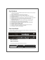
The Front Panel
The front panel consists of the ports and LED indicators. Please refer to the
following paragraph for information.
LEDs Definition
LED for the device:
The switch provides a power LED for the device.
LED
Power
Status
Steady Green
Off
5
Operation
The switch is powered on
The switch is powered off
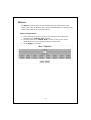
LED for each port:
The switch provides one “1000M” LED and one “10/100M” LED for each port.
1000M LED:
Shows the current transmitting/receiving speed of the
port.
10/100M LED: Shows the link status and the activities on the port.
LED
Status
Green
1000M
10/100M
Operation
The port is connected at 1000 Mbps.
A valid link is established, and there is data
Blinking Green
transmitting/receiving.
No valid link on this port or the port is connected at
Off
10/100 Mbps.
A valid link is established, and there is no data
Steady Green
transmitting/receiving.
A valid link is established, and there is data
Blinking Green
transmitting/receiving.
No valid link on this port or the port is connected at
Off
1000 Mbps.
Attention:The Mini GBIC slot shares the same LED indicator with the
last 4 RJ-45 (copper) port.
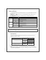
Port Operation
The auto-negotiation feature allows those ports running at one of the
following operation modes:
Media
Speed
1000Mbps
Duplex Mode
Full Duplex
Half Duplex
Full Duplex
Half Duplex
Full Duplex
1000Mbps
Full Duplex
10Mbps
10/100/1000Mbps(copper)
1000Mbps(Fiber)
(mini-GBIC required)
100Mbps
Note: For the last port, when both the fiber and cooper interfaces are
connected, the system adapts the fiber interface and disables the relevant
cooper port automatically.
6
Restore Default Button
You can use this button to reset the switch or restore factory default settings.
To reset the switch, press the button once.
To restore factory default settings, press and hold the button for three
seconds.
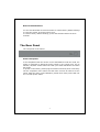
The Rear Panel
The rear panel of the switch:
Power Receptacle
To be compatible with the electric service standards around the world, the
switch is designed to afford the power supply in the range from 100 to
240VAC, 50/60Hz. Please make sure that your outlet standard to be within
this range.
To power on the switch, please plug the female end of the power cord firmly
into the receptacle of the switch and the other end into an electric service
outlet. After the power cord installation, please check if the power LED is lit
for a normal power status.
7
Installation
This switch can be placed on your desktop directly, or mounted in a rack.
Please refer to the instructions for installation.
Before installing the switch, we recommend:
1.
2.
3.
The switch is placed with appropriate ventilation environment. A
minimum 25mm space around the unit is recommended.
The switch and the relevant components are away from sources of
electrical noise such as radios, transmitters and broadband amplifiers
The switch is away from environments beyond recommend moisture
Desktop Installation
1.
2.
Install the switch on a level surface that can support the weight of the
unit and the relevant components.
Plug the switch with the female end of the provided power cord and plug
the male end to the power outlet.
Rack-mount Installation
The switch may be standalone, or mounted in a rack. Rack mounting
facilitate to an orderly installation when you are going to install series of
networking devices.
Procedures to Rack-mount the Switch:
1.
2.
3.
4.
5.
6.
7.
Disconnect all the cables from the switch before continuing.
Place the unit the right way up on a hard, flat surface with the front
facing you.
Locate a mounting bracket over the mounting holes on one side of the
unit.
Insert the screws and fully tighten with a suitable screwdriver.
Repeat the two previous steps for the other side of the unit.
Insert the unit into the rack and secure with suitable screws (optional).
Reconnect all the cables.
8
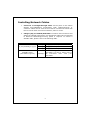
Installing Network Cables
1.
Crossover or straight-through cable: All the ports on the switch
support Auto-MDI/MDI-X functionality. Both straight-through or
crossover cables can be used as the media to connect the switch with
PCs as well as other devices like switches, hubs or router.
2.
Category 3,4,5 or 5eUTP/STP cable: To make a valid connection and
obtain the optimal performance. An appropriate cable that corresponds
to different transmitting/receiving speed is required. To choose a
suitable cable, please refer to the following table.
Media
10/100/1000Mbps copper
1000Mbps Fiber
(mini-GBIC required)
Speed
Wiring
10Mbps Category 3,4,5 UTP/STP
100Mbps Category 5 UTP/STP
1000Mbps Category 5,5e UTP/STP
The cable type differs from the
mini-GBIC you choose. Please refer to
1000Mbps
the instruction came with your
mini-GBIC.
9
Functional Description
Jumbo Frame
With Jumbo Frame supported, it is allowed for the switch to transport
identical data in fewer frames. Hence helps to ensure fewer overheads,
shorten processing time, and reduce interruptions.
Note: To enable Jumbo Frame, Flow Control should be enabled in advance.
Flow Control and Back Pressure
Flow Control and Back Pressure both contributes for lower and higher speed
devices to communicate to each other hence ensures the correctness of
data transmitting. The 802.3x flow control and Back Pressure mechanisms
work respectively for full and half duplex modes. Flow Control can be
enabled or disabled on a per-port basis.
Mirror
The Mirror function provides network administrator to monitor the traffic. By
forwarding a copy of the packets that transferred by the monitored port, the
sniffer port received all the packets and hence is able to monitor the traffic
of the specified port.
VLAN
With VLAN supported, the network can be segmented in groups to reduce
the collisions from widely broadcasting. The device supports both
port-based VLAN and 802.1Q tag based VLAN. Port-based VLAN classifies
incoming packets to VLANs according to their ingress port. The 802.1Q
based VLAN add a tag to the header of the packet to classify their VLANs.
Trunk (Aggregation)
The Trunk functionality integrates several ports to enlarge the bandwidth
that helps to boost the backbone connectivity. The switch allows the
Maximum 8(16-port)/ 12(24-port) groups and 8 members for each group.
Quality of Service (QoS)
The QoS service classifies packets into different precedence. The packets
are transmitted and received by their classified priorities. This mechanism
helps high bandwidth demanded applications such as VoIP to get an
unobstructed connection.
SNMP
This device is SNMP (Simple Network Management Protocol)-management
supported. This allows this product to be monitored or inspected by a SNMP
management station.
10
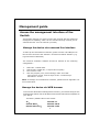
Management guide
Access the management interface of the
Switch
This section instructs you how to enter and proceed with the advanced
management capability, which can be accessed through console port or
Internet Browser over the network (in-band).
Manage the device via command line interface
To start-up the command line interface, please connect a PC COM port to
the RS-232 connector and activate a terminal emulation software (e.g.
HyperTerminal of Windows.)
The terminal emulation software should be started as the following
configuration:
1.
2.
3.
4.
Data rate: 115200 baud.
Data format: 8 data bits, 1 stop bit and no parity.
Flow control: none.
Click the property icon, select settings, make sure that:
“The Function, arrow, and ctrl keys act as”: Terminal keys.
“Emulation”: VT100.
Note: To manage via command line interface, please find the “Appendix” for
more information.
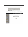
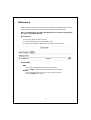
Manage the device via WEB browser
To access the Web-based management interface, you should configure the
management station with an IP address and subnet mask that compatible to
your switch.
The factory default value of the switch:
IP:
Subnet Mask:
Default Gateway:
192.168.1.1
255.255.255.0
192.168.1.254
11
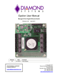
1. Running your Web Browser and enter the IP address “192.168.1.1” in the
Address field.
2. Key in the user name and password to pass the authentication. The factory
default value of User Name and Password is “admin”.
12
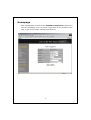
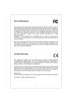
Homepage
After authentication procedure, the “SYSTEM Configuration” page shows
up as the Homepage. You may click the hyperlinks on the left side of each
page to get access to each management functions.
13
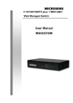
System
The System window provides the switch information and allows users to
configure the switch properties.
Items
MAC Address
S/W Version
IP Address
Subnet Mask
Gateway
Management VLAN
User Name
Password
System Name
Functions
The MAC address of this device.
The software version of this device.
Setup the IP address of the switch.
Setup the Subnet Mask of the switch.
Setup the Gateway of the switch.
The VLAN group that is allowed to access the
WEB-based management interface.
The Login name (Default: admin).
The Login password (Default: admin).
The name of the device.
To save the configuration of the system, click “Apply” to save
Note:
After applying a new IP address, a new login page will be started
automatically. Please login again to proceed to other configurations.
14
Port
This Port Configuration page shows the link status of each port and allows
users to configure speed, flow control and Max frame size for each port.
Items
Link
Mode
Functions
Shows the link status of each port. The column lights
green with the link speed while there is valid connection
on this port.
Select a speed for this port. “Auto Speed” enables
auto-negotiation. “Disable” stop the port from
15
Flow Control
Max Frame length
functioning.
Mark the checkbox to enable the FDX Flow control, or
unmark to disable.
To adjust the size of Jumbo Frame. The length is 1518
bytes. The Maximum value can be up to 9216 bytes.
To save the configuration of the system, click “Apply” to save. You can also click
the “Refresh” button to see the latest status of each port.
16
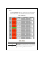
VLAN
VLAN divides the network members into groups to reduce packets collisions
and improve the network efficiency. The switch supports 802.1Q tag-based
VLAN. Please follow the instructions to configure.
To
1.
2.
3.
add new VLAN groups,
Fill in a VLAN id from 2 to 4094 in the “VLAN\Port” column.
Select the ports for each VLAN groups.
Click the “Apply” button to execute.
To delete a VLAN group
1. Clear the members of this VLAN group by clicking those marked
checkboxes.
2. Clear the VLAN id of the VLAN you want to remove in the
“VLAN\Port” column. (Don’t type N/A. Just leave it blank)
3. Click the “Apply” button to execute.
17
Note:
Settings in VLAN, Port aggregation, and Mirror are correlative. Please
make sure that the settings won’t influence each other.
18
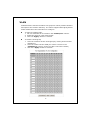
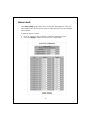
PVID
When the VLAN-enabled switch receives a tagged packet, the packet will be
sent to the port’s default VLAN according to the PVID (port VLAN ID) of the
receiving port.
Items
Port
Functions
Port Number 1~16/24.
Select “tagged” in the drop list to enable the PVID checking and
tag inserting of one port, and select “untagged” to cancel.
For example, if an Egress-tagged port receives an untagged
frame, it will be transmitted as a PVID tagged frame. For the detail
tagging status, please refer to the following table.
Egress
PVID
Only
tagged
Untagged
Tagged
Packet
Packet Frames Packet Frames In Packet Frames
Frames In
Out
Out
Untagged
Untagged
Untagged
Tagged (PVID)
Tagged
Untagged
Tagged (VID)
Tagged (VID)
Pri-tagged
Untagged
Pri-tagged
Tagged (PVID)
Port VLAN ID (1~4094).
Enable: block all un-tagged packets from accessing this port.
Disable: All packets are allowed to access this port.
19
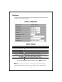
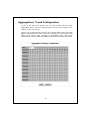
Aggregation/ Trunk Configuration
To set up the Port trunk groups, put the ports number into the same
Aggregation group. There are eight groups to choose. Don’t forget to click
“Apply” to save the setting.
There are three aggregation modes for you to setup, SMAC, DMAC, and XOR.
SMAC mode selects the path of packets according to source MAC while
DMAC mode selects path according to destination MAC. XOR mode
calculates the result of DMAC and SMAC mode to decide the path of packets.
20
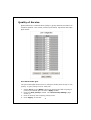
Quality of Service
QoS enhances the communication quality by giving different precedence to
classified packets. This switch provides port-based, tag-based and DSCP
QoS modes:
Port-based mode QoS:
The port-based QoS allows users to configure certain ports as high or low
priority. To give priority level for each port:
1.
2.
3.
4.
Select “Port” in the “Mode” column for those ports that are going to
perform port-based QoS. Click the “Apply” button.
Click the “Port priority” button. The “Port Priority Setting” page
shows up.
Click on the drop list to specify priority levels.
Click “Apply” to execute.
21
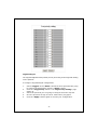
Tag based QoS:
The Tag based QoS decides packet priority according to the tags that adding
on the packets.
To configure Tag Based QoS configuration:
1.
2.
3.
4.
5.
Select “Tagged” in the “Mode” column for those ports that are going
to perform tag-based QoS. Click the “Apply” button.
Click the “Tag priority” button. The “Tag Priority Setting” page
shows up.
Select the port that you are going to configure from the drop list.
Give the priorities as high or low for each Priority Tag types.
Click the “Apply” button again to execute your configuration.
22
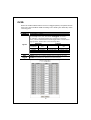
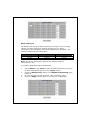
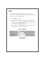
DSCP mode QoS:
The DSCP mode QoS gives packet priority by the types of the incoming
packets. We distinguish those packets according to the “Delay”,
“Throughput” and “Reliability” information attaching on the packet. The
types are listed as the following table:
Bit 0 (Delay)
0 (Normal)
1 (Low)
Bit 1 (Throughput)
0 (Normal)
1 (High)
Bit 3 (Reliability)
0 (Normal)
1 (High)
Note: The device distinguishes packets with DSCP precedence
“000(routine)” only.
To configure DSCP Based QoS configuration:
1.
2.
3.
4.
Select “DSCP” in the “Mode” column for those ports that are going to
perform DSCP-based QoS. Click the “Apply” button.
Click the “DSCP priority” button. The “DSCP Priority Setting” page
shows up.
Give the priorities as high or low for each precedence types.
Click the “Apply” button again to execute your configuration.
23
Mirror
The Mirror function copies all the packets that are transmitted by the
source port to the destination port. It allows administrators to analyze and
monitor the traffic of the monitored ports.
Mirror Configuration:
1.
2.
3.
Select those ports that are going to be monitored by marking the
checkboxes in “Monitor Port” column.
Click the drop list in “Sniffer Port” column. Select a port as the
administration port for monitoring those source ports.
Click “Apply” to activate.
24
Rate Limit
This “Rate Limit” page allows users to limit the bandwidth for each port
and configure the rules for Storm Control, which limits the flow of broadcast
and multicast
To perform Storm Control:
1.
2.
Click on each drop list to specify a speed for each frame type.
Click the “Apply” button to execute your configuration.
25
SNMP
This device supports SNMP-management, which allows network
administrators to monitor and configure this device with SNMP software. To
allow this device to be managed via SNMP:
1.
Select “Enable” in the drop list.
2.
Specify a trap IP. A trap IP is the destination port for sending trap
information, which is usually the IP address of network administrators.
3.
Fill in a name in the “Community Get” column, which is the password
for accessing MIB with read-only authority.
4.
Fill in a name in the “Community Set” column, which is the password
for accessing MIB with read and write authority.
26
Discovery
After installing series of our switches, the discovery management tool helps
users to search and get access to those switches within the LAN.
Note: The discovery tool lists the Maximum 16 devices respectively
for auto and manual modes.
Auto Search
1. Click the “Apply” button to start.
2. The devices being found are listed below.
3. Click the IP address hyperlink to get access to the device.
Manual Add
Add
1. Enter the IP address & name in the text box.
2. Click “Add” to add the new IP address on the table.
Delete
1. Click the check box of the one you want to remove.
2. Click “Delete” to remove.
27
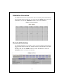
Statistics Overview
The Statistics Overview is provided for users to see the general transmitting
and receiving status of each port. You may click the “Clear” button to clean
all statistics or click the “Refresh” button to renew the statistics.
Detailed Statistics
The Detailed Statistics is provided for users to see the detailed transmitting
and receiving status of each port. Please click the hyperlinks above to select
a port.
You may also click the “Clear” button to clean all statistics or click the
“Refresh” button to renew the statistics.
28
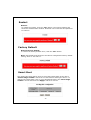
Restart
Restart:
To restart the system, click the “Yes” button. The system restarts and
shows the authentication window. Please fill in the username and password
to continue.
Factory Default
Restore Factory Default:
To restore the factory default value, click the “Yes” button.
Note: The IP address of the device will also be configured as factory-default
setting, which is 192.168.1.1.
Smart Boot
This Smart Boot page allows users to select the booting flash of the device.
“Active image number” shows the current flash for booting the device. To
change the booting flash, click on your demanding flash in the “Boot image
number” column and click the “Apply” button to execute.
29
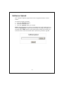
Software Upload
This “Software Upload” page allows users to upgrade firmware for this
switch.
To
1.
2.
3.
perform firmware upgrade:
Click the “Browse” button.
Locate the firmware file.
Click the “Upload” button to execute.
Note: This new firmware is going to be applied on the other flash that you
select in “Smart Boot”, that is, the new firmware is going to be applied on
the flash that is NOT chosen as the booting flash. Please ensure that you
boot this device with correct flash before performing firmware upgrade.
30
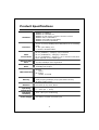
Product Specifications
Standard
IEEE802.3 10BASE-T
IEEE802.3u 100BASE-TX
IEEE802.3x full-duplex operation and flow control
IEEE802.3ab/z 1000BASE-T
IEEE802.1Q VLAN interoperability
IEEE802.1p Priority Operation
Interface
16/24* 10/100/1000Mbps auto MDI/MDI-X RJ-45 switching
ports
4* SFP (mini-GBIC) port
1 * Restore Default Button
Cable
Connections
RJ-45 (10BASE-T): Category 3,4,5 UTP/STP
RJ-45 (100BASE-TX): Category 5 UTP/STP
RJ-45 (1000BASE-T): Category 5,5e or enhanced UTP/STP
Fiber: depend on mini-GBIC types
Network Data
Rate
10/100/1000Mbps Auto-negotiation
Transmission
Mode
10/100Mbps Full-duplex, Half-duplex
1000Mbps Full-duplex
LED Indications
System
Power
RJ-45 Port
1000M, 10/100M
Memory
8K MAC entries
340K(16-port)/500K(24-port) bytes Buffer Memory
9K Byte Jumbo Frame
Emission
FCC Class A, CE, VCCI, RoHS
Operating
Temperature
Operating
Humidity
Power Supply
0° ~ 40°C (32° ~ 104°F)
10% - 90% (non-condensing)
Internal power supply
100-240V/ 50-60Hz universal input
31
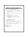
Appendix- Command Line Interface
Start-up and Terminal configuration
To start-up the command line interface, please connect a PC COM port to
the RS-232 connector and activate a terminal emulation software (e.g.
HyperTerminal of Windows).
The terminal emulation software should be started as the following
configuration:
1.
2.
3.
4.
Data rate: 115200 baud.
Data format: 8 data bits, 1 stop bit and no parity.
Flow control: none.
Click the property icon, select settings, make sure that:
“The Function, arrow, and ctrl keys act as”: Terminal keys.
“Emulation”: VT100.
Login/Logout Procedures
To get access to the CLI, you will have to get the username and password
for login. The default username and password are admin/admin.
Note: We recommend users to configure a new username/password to
prevent unauthorized users from accessing to the device.
32
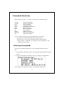
Command Hierarchy
After logging in, press ? + <enter> to show the 9 command groups.
System
Console
Port
VLAN
Aggr
QoS
Mirror
IP
SNMP
Ratelimit
Exit
-
System commands
Console commands
Port commands
VLAN commands
Aggregation commands
QoS commands
Mirror commands
IP commands
SNMP commands
Rate setup commands
Logout commands
Press ? or help to get help. The help depends on the context:
- At top level, a list of command groups will be shown.
- At group level, a list of the command syntaxes will be shown.
- If given after a command, the syntax and a description of the
command will be shown.
Entering Commands
To give any command, please key in your command and press enter.
EX,
1.
Type “System” and press <enter> to get access to the system command
group.
2.
Type “Configuration” and press <enter> to perform “configuration”
You can type “up” and press <enter> to go back to upper level.
33
Command Description
The following session introduces the command structure of the command
line interface.
Command groups:
System
- System commands
Console
- Console commands
Port
- Port commands
VLAN
- VLAN commands
Aggr
- Aggregation commands
QoS
- QoS commands
Mirror
- Mirror commands
IP
- IP commands
SNMP
- SNMP commands
Ratelimit
- Rate setup commands
Exit
- Logout commands
System Commands
Commands at System level:
System
System
System
System
System
System
Configuration [all]
Restore Default [keepIP]
UserName [<name>]
Password [<password>]
Systemname [<name>]
Reboot
System Configuration [all]
Syntax:
System Configuration [all]
Description:
Show system name, username, password, software version and
management MAC address. Optionally show the full configuration.
[all]: Show the total switch configuration (default: System configuration
only).
System Restore Default [keepIP]
Description:
Restore factory default configuration.
[keepIP]: Preserve IP configuration (default: Not preserved).
UserName [<name>]
Description:
Set or show the user name.
34
[<name>]: String of up to 16 characters (default: Show user name).
System Password [<password>]
Description:
Set or show the console password. The empty string ("") disables the
password check.
[<password>]: Password string of up to 16 characters.
System Systemname [<name>]
Description:
Set or show the system name.
[<name>]: String of up to 16 characters (default: Show system name).
System Reboot
Description:
Reboot the switch.
Console Commands
Commands at Console level:
Console Configuration
Console Timeout [<timeout>]
Console Prompt [<prompt string>]
Console Configuration
Description:
Show configured console prompt and timeout.
Console Timeout [<timeout>]
Description:
Set or show the console inactivity timeout in seconds. The value zero
disables timeout.
[<timeout>]: Timeout value in seconds, 0,60-10000.
Console Prompt [<prompt_string>]
Description:
Set or show the console prompt string.
[<prompt_string>]: Command prompt string of up to 10 characters.
35
Port Commands
Commands at Port level:
Port Configuration [<portlist>]
Port Mode [<portlist>] [<mode>]
Port Flow Control [<portlist>] [enable|disable]
Port Admin [<portlist>] [enable|disable]
Port MaxFrame [<portlist>] [<framesize>|reset]
Port Statistics [<portlist>] [clear]
-----#Note: If you want to change maxframe bigger than 1518,
the [Flow Control] should be enabled!
Port Configuration [<portlist>]
Description:
Show the configured and current speed, duplex mode, flow control mode and
admin state for the port.
[<portlist>]: Port list (Default: All ports).
Port Mode [<portlist>] [<mode>]
Description:
Set or show the speed and duplex mode for the port.
[<portlist>]: Port list (Default: All ports).
[<mode>]: Port speed and duplex mode
(Default: Show configured and current mode).
10hdx : 10 Mbit/s, half duplex.
10fdx : 10 Mbit/s, full duplex.
100hdx : 100 Mbit/s, half duplex.
100fdx : 100 Mbit/s, full duplex.
1000fdx: 1 Gbit/s, full duplex.
auto
: Auto negotiation of speed and duplex.
Port Flow Control [<portlist>] [enable|disable]
Description:
Set or show flow control mode for the port.
[<portlist>]: Port list (default: All ports).
[enable|disable]: Enable/disable flow control (default: Show flow control
mode).
36
Port Admin [<portlist>] [enable|disable]
Description:
Set or show the admin state for the port.
[<portlist>]: Port list (default: All ports).
[enable|disable]: Enable or disable admin state (default: Show admin
state).
Port MaxFrame [<portlist>] [<framesize>|reset]
Description:
Set or show the maximum frame size in bytes (including FCS) for frames
received on the port. Tagged frames are allowed to be 4 bytes longer than
the maximum frame size. Use the reset option to return to default setting.
[<portlist>]: Port list (default: All ports).
[<framesize>|reset]: Maximum frame size [1518-9216] or reset to 1518
bytes (default: Show maximum frame size).
Port Statistics [<portlist>] [clear]
Description:
Show or clear statistics for the port.
[<portlist>]: Port list (default: All ports).
[clear]: Clear port statistics (default: Show statistics).
37
VLAN Commands
Commands at VLAN level:
VLAN Configuration [<portlist>]
VLAN Add <vidlist> [<portlist>]
VLAN Delete <vidlist>
VLAN Lookup <vidlist>
VLAN Egress [<portlist>] [untagged|tagged]
VLAN PVID [<portlist>] [<vid>|none]
VLAN OnlyTag [<portlist>] [enable|disable]
VLAN Configuration [<portlist>]
Description:
Show the VLAN egress mode, port VLAN ID and accepted frame type for the
port and the permanently stored VLAN table.
[<portlist>]: Port list (default: All ports).
VLAN Add <vidlist> [<portlist>]
Description:
Add VLAN entry and include ports in member set.
<vidlist>: VLAN ID list.
[<portlist>]: Port list (default: All ports).
VLAN Delete <vidlist>
Description:
Delete VLAN entry (all ports excluded from member set).
<vidlist>: VLAN ID list.
VLAN Lookup <vidlist>
Description:
Lookup VLAN entry and show port list.
<vidlist>: VLAN ID list.
38
VLAN Egress [<portlist>] [tagged|untagged]
Description:
Set or show the VLAN egress mode setting for the port. Egress untagged
ports will strip the VLAN tag from received frames.
Egress tagged ports will not strip the tag from received frames.
[<portlist>]: Port list (default: All ports).
[tagged|untagged]: Port tagged|untagged list (default: Show egress tag
setting).
VLAN PVID [<portlist>] [<vid>|none]
Description:
Set or show the port VLAN ID. Untagged frames received on the port will be
classified to this VLAN ID. Frames classified to this VLAN ID will be sent
untagged on the port.
[<portlist>]: Port list (default: All ports).
[<vid>|none]: Port VLAN ID, 1-4094 (default: Show PVID). The 'none'
option can be used for trunk links.
VLAN OnlyTag [<portlist>] [enable|disable]
Description:
Set or show the onlytag setting of this port.
[<portlist>]: Port list (default: All ports).
[enable|disable]: Only accept tagged frame or not (default: Show disable).
39
Aggregation Commands
Commands at Aggr level:
Aggr Configuration
Aggr Add <portlist>
Aggr Delete <portlist>
Aggr Lookup <portlist>
Aggr Mode [smac|dmac|xor]
Aggr Configuration
Description:
Shows the aggregation groups and the aggregation mode.
Aggr Delete <portlist>
Description:
Delete link aggregation group.
<portlist>: Port list. Aggregations including any of the ports will be deleted.
Aggr Lookup <portlist>
Description:
Lookup and display link aggregation group.
<portlist>: Port list. Aggregations including any of the ports will be shown.
Aggr Mode [smac|dmac|xor]
Description:
Set or show link aggregation traffic distribution mode.
[smac|dmac|xor]: Aggregation mode, SMAC, DMAC or XOR (default: Show
mode).
40
QoS Commands
Commands at QoS level:
QoS Configuration [<portlist>]
QoS Mode [<portlist>] [tag|port|diffserv]
QoS Port [<portlist>] [<class>]
QoS Tagprio [<portlist>] [<tagpriolist>] [<class>]
QoS DiffServ [<dscpno>] [<class>]
<class> range: low|normal|medium|high
QoS Configuration [<portlist>]
Description:
Show the configured QoS mode and the priority setting of all ports.
[<portlist>]: Port list (default: All ports).
QoS Mode [<portlist>] [tag|port|diffserv]
Description:
Set or show the QoS mode for the port.
[<portlist>]: Port list (default: All ports).
[tag|port|diffserv]: Enable tag, port or IP differentiated services class of
service for the port (default: Show mode).
QoS Port [<portlist>] [<class>]
Description:
Set or show the port class. In tag mode, the default class is used for
untagged frames. In port mode, the default class is used as the port priority.
In diffserv mode, the default class is used for non-IP frames.
[<portlist>]: Port list (default: All ports).
[<class>]: Internal class of service (default: Show default class).
QoS Tagprio [<portlist>] [<tagpriolist>] [<class>]
Description:
Set or show the VLAN user priority mapping.
[<portlist>]: Port list (default: All ports).
[<tagpriolist>]: VLAN user priority list, 0-7 (default: All user priorities).
[<class>]: Internal class of service (default: Show class).
41
QoS DiffServ [<dscpno>] [<class>]
Description:
Set or show the IP Differentiated Services mapping.
[<dscpno>]: IP DSCP number, 0-7.
[<class>]: range: low|normal|medium|high
Mirror Commands
Commands at Mirror level:
Mirror Configuration
Mirror Port [<port>]
Mirror Source [<portlist>] [enable|disable]
Mirror Configuration
Description:
Show the mirror destination port and mirror mode for source ports.
Mirror Port [<port>]
Description:
Set or show the mirror destination port.
[<port>]: Mirror destination port (default: Show mirror port).
Mirror Source [<portlist>] [enable|disable]
Description:
Set or show the source port mirror mode.
[<portlist>]: Source port list (default: All ports).
[enable|disable]: Enable/disable mirroring of frames received on port
(default: Show mirror mode).
42
IP Commands
Commands at IP level:
IP Configuration
IP Setup [<ipaddress> [<ipmask> [<ipgateway>]]] [<vid>]
IP Web management [enable|disable]
IP Configuration
Description:
Show IP configured IP address, mask, gateway, VLAN ID and mode.
IP Setup`
Description:
Setup or show IP configuration.
[<ipaddress>]: IP address (default: Show IP configuration).
[<ipmask>]: IP subnet mask (default: Subnet mask for address class).
[<ipgateway>]: Default IP gateway (default: 0.0.0.0).
[<vid>]: VLAN ID, 1-4094 (default: 1).
IP Web management
Description:
Activate or deactivate the Web management.
[enable|disable]: Enable/disable Web management (default: Show Web
management).
SNMP Commands
Commands at SNMP level:
SNMP Configuration
SNMP Community [<get>|<set>] [<community>]
SNMP Setup [enable|disable]
SNMP Trap [<IP Address>]
SNMP Configuration
Description:
Show the SNMP configuration.
SNMP Community [<get>|<set>] [<community>]
Description:
Set or show community setting for SNMP.
[<get>|<set>]: Community for get or set.
[community]: community string.
43
SNMP Setup [enable|disable]
Description:
Activate or deactivate the SNMP.
[enable|disable]: Enable/disable SNMP (default: Show SNMP mode).
SNMP Trap [<IP Address>]
Description:
Set or show SNMP traps destination.
<IP Address>: IP address to send traps to (default: Show trap
configuration).
Ratelimit Commands
Commands at Ratelimit level:
Ratelimit Configuration
Ratelimit Setup <traffic type > <option>
Ratelimit Egress [<portlist>] [enable|disable] [<rate>]
Ratelimit Ingress[<portlist>] [enable|disable] [<rate>]
[<portlist>]: Port list (default: All ports).
[enable|disable]: Enable or disable.
[<rate>]: Set leaky bucket rate in Kbit/s[128/256/512/1024/2048/3072K]
(default: Show rate).
Ratelimit Configuration
Description:
Show the Ratelimit setting.
Ratelimit Setup <traffic type > <option>
Description:
Set or show the ratelimit configuration. The allowed frame rates for ICMP
frames, learn frames, multicasts, broadcasts and flooded unicasts are
controlled using a central ratelimit.
[<traffic type>]: Ratelimit to set. Can be one of:
[ICMP|Broadcast|Multicast] (default: Show all).
[enable|disable]: Enable or disable specified ratelimit.
[<rate>]: Frame rate in kiloframes.
Allowed values are 1k, 2k, 4k, 8k, 16k, 32k, 64k.
44
Ratelimit Egress [<portlist>] [enable|disable] [<rate>]
Description:
Set or show the egress configuration.
[<portlist>]: Port list (default: All ports).
[enable|disable]: Enable or disable egress.
[<rate>]: Disable or set leaky bucket rate in Kbit/s
[128/256/512/1024/2048/3072k] (default: Show egress rate).
Ratelimit Ingress[<portlist>] [enable|disable] [<rate>]
Description:
Set or show the ingress configuration.
[<portlist>]: Port list (default: All ports).
[enable|disable]: Enable or disable ingress.
[<rate>]: Disable or set leaky bucket rate in Kbit/s
[128/256/512/1024/2048/3072k] (default: Show ingress rate).
45