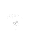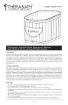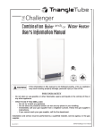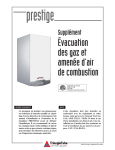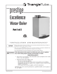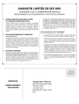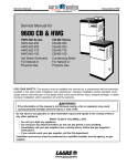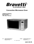
1
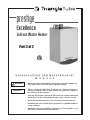
prestige
Excellence
Indirect Water Heater
Part 2 of 2
* I N S TALLAT I O N AN D MAI N T E NAN C E *
M A N U A L
WARNING
IMPORTANT
•
Before proceeding with installation and operation, read entire manual carefully. Failure to do so can cause injury or property damage.
•
When receiving the PRESTIGE Excellence, any claims for damage or
shortage in shipment must be filed immediately against the transportation company by the consignee.
Warranty Registration Card must be filled out by the customer and mailed
within thirty (30) days of installation in order to gain warranty coverage.
•
Revised 8/27/09
•
Retain and affix this manual near the water heater for future reference
•
Installation and service should only be performed by a qualified installer or
service technician.
•
Installations and service should be performed by a license plumber or gas
fitter in the Commonwealth of Massachusetts.
2007-19 Manual Prestige Excellence_IWH
Tables of Contents
Product & Safety Information . . . . . . . . . . . . . . . . . . . . . . . . . . . . . . . . . . 1-2
Pre-Installation . . . . . . . . . . . . . . . . . . . . . . . . . . . . . . . . . . . . . . . . . . . . . . 3-4
Installation - Domestic Piping
Temperature & Pressure (T&P) Relief Valve . . . . . . . . . . . . . . . . . .5
Drain Valve . . . . . . . . . . . . . . . . . . . . . . . . . . . . . . . . . . . . . . . . . . . .6
Automatic Air Vent . . . . . . . . . . . . . . . . . . . . . . . . . . . . . . . . . . . . . .6
Thermal Expansion . . . . . . . . . . . . . . . . . . . . . . . . . . . . . . . . . . . . .6
Water Hammer . . . . . . . . . . . . . . . . . . . . . . . . . . . . . . . . . . . . . . . . .6
Vacuum Breaker . . . . . . . . . . . . . . . . . . . . . . . . . . . . . . . . . . . . . . . .6
General Piping . . . . . . . . . . . . . . . . . . . . . . . . . . . . . . . . . . . . . . . . . .6
Domestic Piping . . . . . . . . . . . . . . . . . . . . . . . . . . . . . . . . . . . . . . . .7
Thermostatic Mixing Valve . . . . . . . . . . . . . . . . . . . . . . . . . . . . . . . .7
Recirculation Piping . . . . . . . . . . . . . . . . . . . . . . . . . . . . . . . . . . . . .7
Storage Tank Applications . . . . . . . . . . . . . . . . . . . . . . . . . . . . . . . .7
Installation - Piping Diagrams . . . . . . . . . . . . . . . . . . . . . . . . . . . . . . . . . .9-10
Water Heater Start-Up
Filling the Inner (Domestic Water) Tank . . . . . . . . . . . . . . . . . . . . .11
Filling the Outer (Boiler Water) Tank . . . . . . . . . . . . . . . . . . . . . . .11
Setting the Thermostat Mixing Valve . . . . . . . . . . . . . . . . . . . . . . . .11
General Notes . . . . . . . . . . . . . . . . . . . . . . . . . . . . . . . . . . . . . . . . . .12
Program Access of the MCBA . . . . . . . . . . . . . . . . . . . . . . . . . . . . .13
Activating the Access Code . . . . . . . . . . . . . . . . . . . . . . . . . . . . . . .13-14
DHW Storage Temperature Setting . . . . . . . . . . . . . . . . . . . . . . . . .15
Setpoint Value Addition for DHW . . . . . . . . . . . . . . . . . . . . . . . . . .15
DHW ON Differential . . . . . . . . . . . . . . . . . . . . . . . . . . . . . . . . . . . .15-16
DHW OFF Differential . . . . . . . . . . . . . . . . . . . . . . . . . . . . . . . . . . .16-17
Additional DHW Feature
Frost Protection . . . . . . . . . . . . . . . . . . . . . . . . . . . . . . . . . . . . .17
Troubleshooting . . . . . . . . . . . . . . . . . . . . . . . . . . . . . . . . . . . . .17
Factory Setting for Parameters . . . . . . . . . . . . . . . . . . . . . . . . .18
Water Heater Maintenance
Maintenance Schedule . . . . . . . . . . . . . . . . . . . . . . . . . . . . . . . . . . .19
Filling Water Heater . . . . . . . . . . . . . . . . . . . . . . . . . . . . . . . . . . . . .19
Draining Water Heater . . . . . . . . . . . . . . . . . . . . . . . . . . . . . . . . . . .19-20
Draining Inner (Domestic Water) Tank . . . . . . . . . . . . . . . . . . . . . . .20
Draining Outer (Boiler Water) Tank . . . . . . . . . . . . . . . . . . . . . . . . .20
i
Tables of Contents
Replacement Parts . . . . . . . . . . . . . . . . . . . . . . . . . . . . . . . . . . . . . . . . . . .21
Water Heater Specifications
Excellence . . . . . . . . . . . . . . . . . . . . . . . . . . . . . . . . . . . . . . . . . . . . .22
Performance
Excellence . . . . . . . . . . . . . . . . . . . . . . . . . . . . . . . . . . . . . . . . . . . . .23
ii
Product & Safety Information
Definitions
The following terms are used throughout this manual to bring attention to the presence of potential hazards or important information concerning the product.
DANGER
NOTICE
Indicates the presence of a hazardous situation which, if ignored, will result in death,
serious injury or substantial property
damage.
Indicates special instructions on installation, operation or maintenance, which are
important to equipment but not related to
personal injury hazards.
WARNING
BEST PRACTICE
Indicates a potentially hazardous situation
which, if ignored, can result in death, serious injury or substantial property damage.
Indicates recommendations made by
Triangle Tube for the installers which will
help to ensure optimum operation and
longevity of the equipment
CAUTION
Indicates a potentially hazardous situation
which, if ignored, may result in minor
injury or property damage.
NOTICE
Triangle Tube reserves the right to modify the technical specifications and components of its products without prior notice.
1
Product & Safety Information
CAUTION
WARNING
Protection must be taken against excessive temperature and pressure!
Bacteria can develop in the domestic water
system if certain minimum water temperatures are not maintained.
TO PROTECT AGAINST EXCESSIVE
TEMPERATURE AND PRESSURE
DANGER
•
Check if the Temperature & Pressure
(T&P) relief valve is installed in the location provided (DHW Side).
•
Check if the 30 psi relief valve supplied
is installed in the location provided (CH
Side)
•
To avoid injury, install the relief devices
to comply with local code requirements.
HOT WATER CAN SCALD!
Water temperature over 125ºF can cause
severe burns instantly or death from scalds.
•
•
Children, disabled and elderly are at highest
risk of being scalded.
-
Never leave them unattended in or
near shower, bathtub or sink.
-
Never allow small children to use a hot
water faucet or draw their own bath.
To avoid any potential scald hazard or if
codes require specific water temperatures at
the hot water faucet, the installer must:
- Install the factory supplied thermostatic
mixing valve at this appliance and ensure it
is working property
and
- Set the domestic storage temperature to the
lowest temperature which satisfies your
hot water needs.
- Feel and adjust water temperature before
bathing or showering.
CAUTION
- Water drained from the system drain
valves may be extremely hot.
To prevent damage to the inner tank, the
Installer must:
TO AVOID INJURY:
- Make sure all connections are tight.
- Direct water flow away from any person.
2
•
Always fill inner tank prior to outer
tank and always drain outer tank prior
to inner tank.
•
Relieve primary system pressure
below 15 psig prior to draining inner
tank.
Pre-Installation
2. The pressure of the heat transfer medium is
maintained less than the normal minimum
operating pressure of the potable water system
Codes Compliance
Installation of the Excellence Water Heater must
conform with the instructions in this manual and
where applicable:
•
•
Exception: Steam complying with section #1 above.
local, state, provincial, and national codes,
laws, regulations and ordinances.
3. The equipment is permanently labeled to
indicate that only additives recognized as
safe by the FDA shall be used in the heat
transfer medium.
in Canada - CAN / CGA B149.1 or B149.2
Installation Code.
Other heat exchanger designs may be permitted
where approved by the Administrative Authority.
Excellence water heater is exempt from ASME
Section VIII, Division 1 Code construction per
Interpretation VIII-86-136. Check with local codes
for applicability.
Operating Restrictions
•
Maximum DHW outlet temperature is
120ºF, when factory supplied mixing valve
is installed.
NOTICE
The Excellence water heater will absorb less
than 200,000 BTU/hr when domestic water
outlet temperature is 194ºF and boiler water
supply temperature is 240ºF. Listed outputs
are based on ASME Section VIII
Interpretation VIII-1-86-136.
•
Maximum boiler water temperature is
194ºF.
•
Maximum working pressure for inner
(domestic water) tank is 150 psig.
•
Where recommendations in this manual differ
from local, or national codes, the local or national
codes take precedence.
Maximum working pressure for outer
(boiler water) tank is 30 psig.
•
pH and chloride limits for water heaters
are:
- chloride, less than 150 mg/l
- pH value min. 6 - max. 8
Codes Restrictions
Single wall heat exchanger in the Excellence water
heater complies with National Standard Plumbing
Code, provided that:
NOTICE
– boiler water (including additives) is practically
non-toxic, having toxicity rating or class of 1,
as listed in Clinical Toxicology of Commercial
Products, and
Any water conditioning system must be
installed and maintained in accordance with
manufacturer’s specifications.
– boiler water pressure is limited to maximum
30 psig by approved relief valve.
NOTICE
Do not install the Excellence water heater on
any application if the boiler piping contains
non-oxygen barrier tubing or if the boiler
piping is considered an “open system”.
Exposing the outer tank of the Excellence
water heater to oxygen contamination will
lead to premature tank failure and denial of
the warranty.
Single wall heat exchangers are permitted under the
Uniform Plumbing Code - Paragraph L3.2. and L3.3
if they satisfy all of the following requirements.
1. The heat transfer medium is potable water or
contains only substances which are recognized as safe by the U.S. Food and Drug
Administration.
3
Pre-Installation
Locating Water Heater
•
The Excellence is not intended for outdoor
installations.
•
Locate Excellence so that any leakage from the
tank or water connections will not cause damage to the area adjoining the water heater or to
lower floors in the structure.
NOTICE
When maintaining zero clearance or less
than recommended clearances, some product labeling may become hidden and
unreadable
WARNING
Recommended Clearances
The Excellence is approved for zero clearance to
combustibles, excluding vent and boiler piping.
-
When installing the Excellence in a confined
space, sufficient air must be provided for
proper combustion and venting and to
allow, under normal operating conditions,
proper air flow around the product to maintain ambient temperatures within safe limits
to comply with the National Fuel Gas Code
NFPA 54 - latest edition. Reference the
Excellence Boiler Manual for additional
guidelines.
Vent & Boiler Piping - 1/4 inch from combustible materials.
BEST PRACTICE
To provide serviceability to the unit it is recommended that the following clearances be
maintained:
Residential Garage Installations
When installing the Excellence in a residential
garage, the following special precautions per NFPA
54/ANSI Z223.1 must be taken:
Top boiler jacket - 24 inches.
Front - 24 inches.
Bottom boiler piping - 24 inches.
-
Mount the unit with a minimum 18 inches
above the floor level of the garage. Ensure
the burner and ignition devices / controls
are no less than 18 inches above the floor
level.
-
Locate or protect the unit in a matter so it
cannot be damaged by a moving vehicle.
Rear - 0 inches
Sides - 6 inches
4
Installation - Domestic Piping
Temperature & Pressure (T&P) Relief Valve
•
CAUTION
To reduce risk of excessive pressures and temperatures in the water heater, install temperature and pressure protective equipment
required by local codes, but no less than a combination temperature and pressure relief valve
certified by a nationally recognized testing laboratory that maintains periodic inspection of
production of listed equipment or materials, as
meeting the requirements for Relief Valves and
Automatic Gas Shutoff Devices for Hot Water
Supply Systems, ANSI Z21.22. This valve must
be marked with a maximum working pressure
of the water heater.
Install the T&P in the run (straight through leg)
of a tee located at the domestic hot water outlet. Use a long element T&P relief valve, as
shown in Fig. 3 page 8.
T&P Relief Valve Discharge Piping
T&P relief valve discharge piping must be:
- made of material serviceable for temperatures of 250ºF or greater.
- directed so that hot water flows away from
all persons.
- directed to a suitable place for disposal.
- installed so as to allow complete draining
of the T&P relief valve and discharge line.
T&P relief valve discharge piping must not be:
•
The Excellence water heater must be protected
with a T&P relief valve.
- excessively long. Using more than 2
elbows or 15 feet of piping can reduce discharge capacity.
•
Size the Excellence T&P relief valve by the
following specifications, unless they conflict
with local codes: 3/4” NPT with an AGA
Rating of 100,000 BTU/hr (Watts 100XL-8 or
equivalent).
- directly connected to a drain. Terminate
discharge piping within 6” from drain.
Refer to local codes.
- plugged, reduced or restricted.
- subject to freezing.
NOTICE
WARNING
For proper operation of the T&P and to prevent the T&P from activating due to boiler
water temperature, use a T&P relief valve
with extended element. A 8” minimum
length is recommended.
Do not install any valve between T&P relief
valve and tank connection or on T&P relief
valve discharge piping. Do not plug T&P
relief valve or discharge piping. Improper
placement and piping of T&P relief valve
can cause severe personal injury, death or
substantial property damage.
Standard Installation
• Install T&P relief valve in the Auxiliary connection located behind the air vent on the top of
the water heater as shown Fig. 2 page 8.
Commonwealth of Massachusetts Installation
Follow this procedure for jurisdictions requiring a
vacuum breaker to be installed on the domestic
cold water inlet.
5
Installation - Domestic Piping
Drain Valve
CAUTION
Drain valve and fittings are supplied by others.
Standard Installation
•
Install a tee connection at the domestic cold
water inlet, as shown in Fig. 4, pages 9.
•
Pipe the drain piping with drain valve from
the tee connection to:
- a suitable place for disposal
or
- terminate within 12” of the floor
T&P relief valve is not intended for constant
duty, such as relief of pressure due to
repeated normal system expansion. Correct
this condition by installing a properly sized
expansion tank in domestic water system.
Refer to expansion tank manufacturer’s
installation instructions for proper sizing.
Water Hammer
Dishwashers, clothes washers and fast-closing positive shut-off valves incorporated in the system all
contribute to creating water shock. Install a water
hammer arrester to prevent damage to pipes and
appliances. See device manufacturer’s instructions
for application and installation.
Commonwealth of Massachusetts Installation
•
Thread a 3/4” close nipple onto the
Auxiliary connection and insert an openend dip tube into the Auxiliary connection
on top of water heater. As shown in Fig. 3,
page 8.
•
Install a 3/4” NPT elbow to the Auxiliary
connection.
•
NOTICE
Pipe the drain piping with drain valve from
the elbow connection to:
- a suitable place for disposal
or
- terminate within 12” of the floor
Water hammering within the domestic piping system can cause premature failure of
the inner tank of the water heater. This type
of failure is NOT covered under warranty.
Vacuum Breaker
Automatic Air Vent
Installing a vacuum breaker on the domestic cold
water outlet will prevent damage to the inner tank
if a negative pressure is developed in the domestic
supply line. See manufacturer’s instructions for
application and installation of the vacuum breaker.
1. Install automatic air vent provided using
suitable pipe dope or tape in the air vent connection as shown in Fig. 2 and 3 page 8.
2. Unscrew vent cap on air vent one full turn.
Leave cap unscrewed one turn for normal
venting.
General Piping
Thermal Expansion
If a backflow preventer, check valve or pressure
reducing valve is piped on cold water supply piping
of water heater, install an expansion tank on cold
water supply line to prevent normal thermal expansion from repeatedly forcing open T&P relief valve.
6
•
For domestic water piping diagrams, see pages
9 and 10.
•
All plumbing must meet or exceed all local,
state and national plumbing codes.
•
Use pipe dope or tape suitable for potable
water systems.
•
Use isolation valves to isolate system components.
Installation - Domestic Piping
Domestic Piping
•
DANGER
Union on domestic hot water outlet should be
piped at a higher elevation than domestic water
drain valve. This will make draining the water
heater easier.
•
Use dielectric unions or couplings to protect
hot and cold water fittings from corrosion
when connecting dissimilar materials such as
copper and galvanized iron pipe.
•
If copper pipe is used for domestic water connections, first solder pipe to a threaded adapter
and then screw adapter into cold water inlet on
top of Excellence. Cold Water Inlet contains
an internal plastic dip tube which can be damaged by heat from soldering.
For proper operation of the thermostatic
mixing valve and to prevent potential scalding hazards, the recirculation loop should
be controlled by an aquastat. DO NOT use
continuous recirculation.
Check Valve
NOTICE
ld
Co
Do not apply heat to the cold water inlet
when making sweat connections to water
heater. Sweat tubing to adapter before fitting adapter to cold water inlet of heater. It
is imperative that no heat be applied to the
cold water inlet, as it contains a non metallic dip tube.
•
t
Ho
Adapter
Mixed
Fig. 1: Mixing Valve Assembly
Recirculation Piping
When the water supply pressure is higher than
70 psig, it is recommended to install a pressure
reducing valve on cold water supply line to
prevent water loss through T&P relief valve.
Thermostatic Mixing Valve
•
Recirculation piping must be installed in the
cold water inlet as shown Fig. 5, page 9.
•
A stainless steel or bronze circulator is recommended.
Storage Tank Application
The Excellence is factory supplied with a thermostatic mixing valve with built-in check valve. The
mixing valve must be installed as shown in Fig. 1.
For applications requiring large volumes of domestic hot water in a relative short period, the installer
may include a storage type tank (see Fig. 6 page 10)
in the domestic piping.
The operating range of the thermostatic mixing is
90ºF to 120ºF.
The installer must:
For applications with a domestic recirculation
loop, the recirculation pump should be controlled
by an aquastat. The maximum recommended setting of the aquastat is 10ºF lower than the thermostatic mixing valve setting.
1. Relocate the thermostatic mixing valve from
the Excellence to the outlet of the storage
tank.
2. Provide recirculation from the storage tank
back to the Excellence using a bronze type
circulator. Maximum recommended recirculation flow rate is 1 gpm.
7
Installation - Domestic Piping
DHW
Hot Water
Outlet
T&P Valve
(Drain Piping Not Shown)
DHW Aux.
Connection
DHW
Cold Water
Inlet
Air Vent
Connection
Fig. 2: Standard Installation of the T&P Relief Valve
T&P Valve
(Drain Piping Not Shown)
Drain
Dip Tube
3/4” Brass
Tee
3/4” Brass Close
Nipple
DHW
Hot Water
Outlet
DHW Aux.
Connection
Air Vent
Connection
DHW
Cold Water
Inlet
Fig. 3: Commonwealth of Massachusetts Installation
8
Installation - Piping Diagrams
12" Min.
Heat Trap
Loop
(Optional)
12" min.
Heat Trap
Loop
(Optional)
C
3
4
H
8
5
M
6
1
Cold Water
Inlet
9
Fig. 4: Standard Installation Domestic Piping Excellence Series
Fig. 5: Standard Installation Domestic Piping with Optional Recirculation Excellence Series
1.
2.
3.
4.
5.
6.
7.
8
9.
Shut-off valve
Flow check valve
Mixing valve with check valve
Vacuum Breaker *
Unions
Backflow preventer or pressure reducing valve(*)
Circulator (controlled by aquastat)
Domestic drain valve
Thermal expansion tank (potable)
(*) Optional devices may be required by local codes.
9
Installation - Piping Diagrams
Optional
recirculation
2
7
M
C
N
3
Optional 12" Heat trap
1
4
8
6
3
Cold water
inlet
9
3
7
2
Fig. 6: Domestic Piping with Optional Storage Tank
1.
2.
3.
4.
6.
7.
8
9.
Mixing valve with check valve
Flow check valve
Shut-off valve
Backflow preventer or pressure reducing valve(*)
Thermal expansion tank
Circulator (controlled by aquastat)
Domestic drain valve
Vacuum Breaker *
(*) Optional devices may be required by local codes.
10
Water Heater Start-Up
Filling the Inner (Domestic Water) Tank
WARNING
CAUTION
•
Never use the Excellence unless inner and
outer tank of the water heater is completely
filled with water.
•
Inner tank of the Excellence water heater
must be completely filled and pressurized
before pressurizing outer tank.
Do not use automotive, ethylene glycol or
petroleum-based antifreeze. Do not use any
undiluted antifreeze. This can cause severe
personal injury, death or substantial property
damage.
Setting the Thermostatic Mixing Valve
NOTICE
1. Close domestic water drain valve.
The thermostatic mixing valve controls the
outlet hot water temperature delivered to
the faucets.
2. Open domestic water isolation valves on the
water heater piping.
3. Vent air from inner (domestic water) tank by
opening nearest hot water faucet. Fill domestic water tank completely by allowing water to
run until there is a constant flow of water.
WARNING
POTENTIAL SCALD HAZARD. The mixing valve must be installed on the
Excellence. Removal of the mixing valve
will create a potential scald hazard resulting
in severe personal injury or death.
4. Close hot water faucet.
Filling the Outer (Boiler Water) Tank
If any adjustment needs to be made on the valve:
CAUTION
•
•
Never use the Excellence unless inner and
outer tank of the water heater is completely
filled with water.
Inner tank of the Excellence water heater
must be completely filled and pressurized
before pressurizing outer tank.
-
Use a L-Key to remove the set screw securing
the knob to the valve.
-
Remove the knob and lock ring from the valve.
-
Replace the knob and adjust the set temperature of the valve to the desired temperature.
NOTICE
NOTICE
To calibrate the outlet temperature, allow
the water to run for approximately 2 minutes and measure the water with a thermometer. To adjust the valve setting, rotate
the knob clockwise to decrease the water
temperature or counter-clockwise to
increase the water temperature.
Reference the PRESTIGE Excellence boiler
manual for boiler start-up and guidelines for
filling the boiler.
If antifreeze is used in boiler water, check concentration. Boiler water (including additives) must be
practically non-toxic, having toxicity rating or class
of 1, as listed in Clinical Toxicology of Commercial
Products.
11
-
Once the desired temperature is achieved,
remove the knob and refit the lock ring onto the
valve’s “Mix” marking.
-
Locate the tab on the inner face of the knob
into the retainer in the locking ring. Secure the
knob with set screw.
Water Heater Start-Up
DANGER
HOT WATER CAN SCALD!
•
Water temperatures over 125ºF can cause
severe burns instantly, or death from scalds.
•
Feel water before bathing or showering.
•
Consumer Product Safety Commission and
some states recommend temperatures settings of
130ºF or less. Setting thermostat higher than
130ºF will increase risk of scald injury and
cause severe personal injury or death.
•
Water heated to a temperature suitable for
clothes washing, dish washing and other sanitizing needs will scald and cause permanent injury.
•
Children and elderly, infirm, or physically
handicapped persons are more likely to be
injured by hot water. Never leave them unattended in or near a bathtub. If anyone using hot
water in the building fits this description, or if
state laws or local codes require certain water
temperatures at hot water faucets, take special
precautions.
- Install the factory supplied automatic mixing valve at water heater and/or install a
point of use mixing valve at each hot water
faucet, bath and shower outlet. Selection
and installation of point of use mixing
valves must comply with valve manufacturer’s recommendation and instructions.
- Use the lowest practical temperature setting.
- Check water temperature after any adjustment of the mixing valve.
12
General Notes
•
Household water usage patterns will affect
water temperature at any faucet or shower.
Occasionally check temperature at each point
of use, then adjust the mixing valve setting
accordingly. Always recheck temperature after
adjusting the mixing valve.
•
Lowering the automatic mixing valve as indicated in these instructions will reduce water temperature levels. Consult your installer or service
technician.
Water Heater Start-Up
Important Information - Read Before
Proceeding
Activating the Access Code
To enter the parameter listing of the MCBA control, the installer must enter the service code as follows:
WARNING
This document is intended to be used by a
factory trained and qualified heating contractor or service technician only. Read all
instructions within this document and within the PRESTIGE Excellence Boiler
Installation and Maintenance Manual,
before proceeding. It is recommended to
follow the procedures in the steps given,
skipping or missing procedural steps could
result in severe personal injury, death or
substantial property damage.
1. Press and hold the MODE button
2.
The display should read CODE
3. Release the STEP and MODE buttons on the
control panel.
4. Press STEP once.
(XX
The display should read C_XX
should be a random number from 00 to 99)
Program Access of the MCBA CONTROL
To adjust the factory parameter setting of the
Prestige MCBA Control, the installer must enter
into the Parameter menu of the control.
5.
Press the + or - button to change the display
number C_XX to read C_54. Press and release
the + or - to change the display one number at
a time. Press and hold the + or - to rapidly
change the display number.
6.
When the display reads C_54 press STORE to
save the service code. The display C_54
should flash when the code is entered and
saved.
WARNING
Do not attempt to revise any other control
parameter setting except those listed in this
supplement. Perform only those parameter
revisions described in this supplement.
Failure to comply could result in erratic or
unreliable operation of the Prestige resulting in severe personal injury, death or substantial property damage.
Continue holding the MODE and press STEP
button until STBY appears and hold both STEP
and MODE buttons for 2 to 3 seconds.
NOTICE
After the service code is entered press the MODE
button until the display shows PARA. At this point
the installer can access the parameters required for
application.
For additional information on revising the
Prestige MCBA Control Module operational
parameter settings, reference the Prestige
Control Supplement.
Once in the parameter mode, press the STEP
repeatedly to reach the appropriate parameter setting. The display should show the following
sequence, as the STEP button is press repeatedly:
1140
Press STEP x2 - 2_01
Press STEP x3 - 3_01
Press STEP x4 - 4186
Press STEP once-
13
Water Heater Start-Up
P_10
Press STEP x6 - P_11
Press STEP x5 -
WARNING
Etc......
After Parameter 4 the display will show P followed
by a two-digit number that increases with each
press of the STEP button.
NOTICE
The actual parameter values displayed on
the unit may vary depending on the application. The parameter sequence will always
occur in the order shown.
Once a particular parameter is reached, release the
STEP button. Wait a second and the display will
show the current setting for that parameter in the
right two display digits.
To Change a Parameter Setting
Use the + or - button to change the value of
the display.
Press the STORE button once to save the
change.
If a parameter setting is changed from the
factory default and the STORE button is not
pressed to save the setting, the MCBA module will automatically store the setting after
15 minutes. Ensure all parameters settings
are either factory default or revised based
on the application. Review all parameters
settings on page 18 when completed and
prior to commission of the boiler. Failure to
comply could result in erratic or unreliable
operation of the Prestige boiler.
NOTICE
Once a parameter setting value has been
revised and stored, if the STEP button is
pressed for the next parameter setting the
value setting of that parameter will appear.
The display will not show P_XX of the next
sequential parameter. The sequence of
parameters may be scrolled through, as the
display will roll over from parameter 46 to
parameter 1.
BEST PRACTICE
If sequential parameters are being revised
and since the display will not show P_XX of
the sequential parameter, it is recommended
to press and hold the STEP button to scroll
through the entire list of parameters before
making any additional changes to avoid any
potential confusion.
14
Water Heater Start-Up
DHW Storage Temperature Setting
The parameter setting for the DHW storage temperature is Parameter 1 and is accessible without
having to enter the service code.
To revise the parameter setting within the Prestige
Control Module for the set point of the Domestic
Storage temperature, the installer can access the
parameter setting by entering the Parameter Mode
PARA during normal operation, the service code is
not required.
To revise the parameter setting within the Prestige
Control Module for the Setpoint Value Addition for
DHW, the installer must activate the service code
for the control module as previously described in
the Program Access of the MCBA section.
1. Enter into the service code mode.
2. Once the service code has been entered and
accepted, press MODE until the display shows
PARA.
3. Press STEP until the display shows P_21.
This parameter setting is the Setpoint Value
Addition for DHW parameter. After releasing
the STEP button the display will show the current setting.
1. Press MODE once until the display shows
PARA.
2. Press STEP until the display shows 1140 or
1XXX (where XXX is a setting other than the
factory setting).
4. Press the + or - button until the desired setting
is achieved. Press STORE to save the setting.
The display will flash when the revised setting
is accepted.
3. Press the + or - button until the desired DHW
storage temperature setting is achieved. Press
STORE to save the setting. The display will
flash when the revised setting is accepted.
5. Once the desired parameter setting has been
revised and stored within the Prestige Control
module, press RESET to exit the CODE mode.
Setpoint Value Addition for DHW
DHW ON Differential
To achieve the boiler operating temperature during
a DHW request for heat, the MCBA Control uses
Parameter 1 and a second parameter, Parameter 21
Setpoint Value Addition for DHW. Parameter 1
plus Parameter 21 will establish the boiler operating temperature limit.
The MCBA Control Module has 2 differential settings for the burner operation. The first differential
setting the installer has the option of adjusting, is
Parameter 38 DHW ON Differential. This parameter sets the DHW storage temperature low limit. The
burner operation will respond when the DHW storage temperature drops below Parameter 1 minus
Parameter 38 setting.
If Parameter 1 is set below 134ºF, it is recommended that Parameter 21 be reset to a higher setting. The request for DHW is based on the temperature reading of the DHW sensor and its relationship to Parameter 1. The operating boiler temperature setpoint is based on Parameter 1 plus
Parameter 21 with a maximum operating temperature of 194ºF.
15
A minimum DHW ON Differential parameter setting
will create a quicker burner operation response to
any domestic water draws from the Excellence tank.
In contrast, a maximum DHW ON Differential setting will result in a delay response to domestic
draws.
Water Heater Start-Up
DHW OFF Differential
DANGER
The DHW ON Differential setting of Parameter
38 greatly affects the production of domestic hot
water. A minimum setting of Parameter 38 could
result in a rapid response to a DHW request for
heat resulting in a potential scald hazard. It is
strongly recommended that the installer utilize
the factory supplied thermostatic mixing valve
on the DHW outlet of the Excellence. Failure to
comply could result in severe personal injury,
death or substantial property damage.
To revise the parameter setting within the Prestige
Control Module for DHW ON Differential control,
the installer must activate the service code for the
control module as previously described in the
Program Access of the MCBA section.
1. Enter into the service code mode.
2. Once the access code has been entered and
accepted, press MODE until the display shows
PARA.
3. Press STEP until the display shows P_38..
This parameter setting is the DHW ON
Differential parameter. After releasing the
STEP button the display will show the current
setting.
The second differential setting is Parameter 39
DHW OFF Differential. This parameter sets the
DHW storage temperature high limit. The burner
operation will cease when the DHW storage temperature rises above Parameter 1 plus Parameter
39.
A maximum DHW OFF Differential parameter setting will result in an extended burner firing cycle
when responding to any domestic water draws
from the Excellence. This extended burner firing
cycle could result in a final storage temperature of
the domestic hot water that is higher than the
desired storage temperature setting.
DANGER
The DHW OFF Differential setting of
Parameter 39 greatly affects the production
of domestic hot water. A maximum setting of
Parameter 39 could result in an excessive
domestic storage temperature resulting in a
potential scald hazard. It is strongly recommended that the installer utilize the factory
supplied thermostatic mixing valve on the hot
water outlet of the Excellence. Failure to
comply could result in severe personal injury,
death or substantial property damage.
To revise the parameter setting within the Prestige
Control Module for DHW OFF Differential control, the installer must activate the service code for
the control module as previously described in the
Program Access of the MCBA section.
4. Press the + or - button until the desired setting
is achieved. Press STORE to save the setting.
The display will flash when the revised setting
is accepted.
5. Once the desired parameter setting has been
revised and stored within the Prestige Control
module, press RESET to exit the CODE mode.
16
1. Enter into the service code mode.
2. Once the access code has been entered and
accepted, press MODE until the display shows
PARA.
3. Press STEP until the display shows P_39.
This parameter setting is the DHW OFF
Differential parameter. After releasing the
STEP button the display will show the current
setting.
Water Heater Start-Up
Troubleshooting
Error Codes
b_38 alternating with a status code of 9
4. Press the + or - button until the desired setting
is achieved. Press STORE to save the setting.
The display will flash when the revised setting
is accepted.
5. Once the desired parameter setting has been
revised and stored within the Prestige Control
module, press RESET to exit the CODE mode.
Additional DHW Features
Frost Protection
Through the use of the IDWH sensor, the Prestige
Excellence Control module will now provide a
Frost Protection feature to the water heater.
The Frost Protection feature is designed to protect
the Excellence water heater from a potential freeze
up. The protection is activated once the IDWH
sensor records a domestic temperature below 38ºF.
At that time the Prestige Excellence will begin the
burner function at low input, the circulator will
begin circulating and the internal 3-way valve will
open. The burner will continue operating at minimum input with circulator energized until the sensor senses a domestic water temperature above
50ºF. At that point the boiler will shut down the
burner function and circulator. This feature is
always active even if the DHW operation is in the
OFF mode and cannot be overridden.
17
The IDWH Sensor is not properly connected to the Prestige low voltage terminal
strip. Check for proper connections and
proper terminals
b_33 alternating with a status code of 9
The IDWH Sensor is short-circuited.
Check for proper connections to the
Prestige low voltage terminals.
Once the condition is corrected, the errors will
automatically reset and the Prestige Excellence
will return to normal operation.
Water Heater Start-Up
FACTORy SETTING FOR PARAmETERS
18
Water Heater Maintenance
Check function of field-installed controls
and valves. See component manufacturer’s
instructions.
Maintenance Schedule
Annual service by qualified service technician
should include the following:
Review homeowner’s maintenance responsibilities and their frequencies, including any
not listed in the following section.
Any procedure required by local codes.
Check air vent operation.
Verify system pressure. Air venting procedure may require adding water to bring system up to pressure, typically 12 psig.
Manually operate T&P relief valve at least
once a year. This will release some hot
water.
Homeowner monthly maintenance to include:
Check air vent operation.
•
WARNING
Before operating T&P relief valve, make
sure no one is in front of or around T&P
relief valve discharge piping. Hot discharge
water can cause severe personal injury or
substantial property damage.
Move operating lever to open position for a
few seconds and then move it back, allowing
it to snap closed. After T&P relief valve is
operated, if it continues to release water,
close cold water inlet to water heater immediately. Follow draining instructions, and
replace T&P relief valve. If T&P relief valve
weeps periodically, it may be due to thermal
expansion see Thermal Expansion, page 6.
Do not plug T&P relief valve or discharge
piping.
Automatic air vent - remove cap. Briefly
push in valve and release it to clean valve
seat. Screw cap on completely, then
unscrew one full turn. If air vent does not
operate, call qualified service technician.
Visually check valves, pipes and fittings for
leaks. Call qualified service technician to
repair leaks.
Filling Water Heater
See “Filling the Outer (Boiler Water) Tank” and
“Filling the Inner (Domestic Water) Tank on page
11.
Draining Water Heater
Drain water heater if it will be shut off and exposed
to freezing temperatures. Freezing water will
expand and damage water heater.
•
If boiler water contains sufficient
antifreeze, then only the domestic water
needs to be drained.
WARNING
WARNING
Plugging T&P relief valve or discharge piping can cause excessive pressure in water
heater, resulting in severe personal injury,
death, or substantial property damage.
Follow instructions on circulator to oil it, if
required.
Check mixing valve, valves, pipes and fittings for leaks.
19
Close boiler water isolation valves and
relieve system pressure to below 15 psig in
outer tank before draining inner tank to
prevent damage to inner tank.
•
If boiler water does not contain sufficient
antifreeze, then the boiler water and
domestic water must be drained.
Water Heater Maintenance
If antifreeze is used in boiler water, check concentration. Boiler water (including additives) must be
practically non-toxic, having toxicity rating or
class of 1, as listed in Clinical Toxicology of
Commercial Products. A maximum 50/50 mixture
of inhibited propylene glycol is recommended.
Follow antifreeze manufacturer’s instruction.
WARNING
Do not use automotive, ethylene glycol or
petroleum-based antifreeze. Do not use
any undiluted antifreeze. This can cause
severe personal injury, death or substantial
property damage.
Draining Inner (Domestic Water) Tank
(See Domestic Piping Fig. 4 page 9)
1. Disconnect power supply to water heater.
- If outer (boiler water) tank pressure is
greater than 15 psig, relieve boiler pressure and close isolation valves before proceeding.
2. Close system supply isolation valve.
3. Connect a hose to domestic water drain valve
at cold water inlet. Hose should extend to
drain at floor level to allow siphoning of
domestic water tank.
4. Open hot water faucet at highest point above
heater.
WARNING
Water from opened drain valves, unions
and other connections may be extremely
hot. To avoid severe personal injury, death
or substantial property damage:
- Tighten all drain hose connections.
- Direct hot water away from all persons.
Draining Outer (Boiler Water) Tank
1. Disconnect power supply to water heater.
2. Close boiler water isolation valves between
boiler and water heater.
3. Connect hose to boiler water drain valve at
water heater. Open and drain water to a safe
place.
4. To speed draining procedure, loosen air vent
on top of tank.
5. When draining is complete, close drain valve
and retighten air vent.
20
5. Open domestic water drain valve to start
siphoning.
6. When draining is complete, close hot water
faucet and domestic water drain valve.
Replacement Parts
3
1
2
Fig. 7: Excellence Domestic Components
21
Water Heater Specifications
20.8"
529 mm
24.7"
628 mm
20.4"
516 mm
3” Vent Outlet
14.8"
377 mm
12"
306 mm
15"
381 mm
3” Combustion
Air Inlet
11.4"
289 mm
3/4” NPSC
Pressure Relief
Valve Connection
3/4” NPSC
Pressure Relief Valve
Connection
3” Vent Outlet
3” Combustion Air Inlet
37.2”
945 mm
7.2"
183 mm
15.9"
405 mm
15.9"
405 mm
18.9" - 479 mm
1/2” NPSC Boiler Drain
2.4" - 61 mm
1/2” NPT Gas Connection
1” NPT Boiler Return
8.0"
205 mm
1/2” NPT Gas
Connection
16"
406 mm
1” NPT Boiler Supply
Front View
Side View
22
1/2” NPSC
Boiler Drain
1” NPT Boiler Supply
1” NPT Boiler Return
Water Heater Specifications
3/4” NPT DHW Outlet
11.3"
286 mm
7.3"
186 mm
3.4”
87 mm
3/4” NPSC Aux. Connection (Rear)
1/2” NPSC Air Vent Connection
3/4” NPT
DHW Inlet
4.1”
105 mm
Top View
Performances
23
8”
204 mm
Additional quality water heating equipment available from: Triangle Tube
Smart Indirect Fired Water Heaters
-
Exclusive Tank-in-Tank design
Stainless steel construction
Available in 8 sizes and 2 models
Limited LIFETIME residential warranty
15 year limited commercial warranty
Self cleaning/self descaling design
-
For domestic water, snow melting, radiant floor,
refrigeration
Plates made of stainless steel, with a 99.9 % copper
and brazed, ensuring a high resistance to corrosion
Self cleaning and self descaling
Computerized sizing available from Triangle
Tube/Phase III
Available in capacities from 25,000 BTU/hr to
5,000,000 BTU/hr
UL Listed
TTP Brazed Plate Heat Exchangers
-
Maxi-flo Pool and Spa Heat Exchangers
-
Construction of high quality corrosion resistant
stainless steel (AISI 316)
Specially designed built-in flow restrictor to assure
maximum heat exchange
Compact and light weight
Available in 5 sizes that can accommodate any size
pool or spa
Freeway Center - 1 Triangle Lane - Blackwood, NJ 08012
(856) 228 8881 Fax (856) 228 3584
http:\\www.triangletube.com / [email protected].
Member of
Group